EP3725419A1 - Applikator für beschichtungsmittel, auftragsanlage, die einen solchen applikator umfasst, und auftragsverfahren mithilfe dieses applikators - Google Patents
Applikator für beschichtungsmittel, auftragsanlage, die einen solchen applikator umfasst, und auftragsverfahren mithilfe dieses applikators Download PDFInfo
- Publication number
- EP3725419A1 EP3725419A1 EP20170084.6A EP20170084A EP3725419A1 EP 3725419 A1 EP3725419 A1 EP 3725419A1 EP 20170084 A EP20170084 A EP 20170084A EP 3725419 A1 EP3725419 A1 EP 3725419A1
- Authority
- EP
- European Patent Office
- Prior art keywords
- applicator
- nozzles
- faces
- face
- printing nozzles
- Prior art date
- Legal status (The legal status is an assumption and is not a legal conclusion. Google has not performed a legal analysis and makes no representation as to the accuracy of the status listed.)
- Granted
Links
- 239000011248 coating agent Substances 0.000 title claims abstract description 31
- 238000000576 coating method Methods 0.000 title claims abstract description 31
- 238000000034 method Methods 0.000 title claims description 22
- 238000009434 installation Methods 0.000 title claims description 16
- 238000011144 upstream manufacturing Methods 0.000 claims description 3
- 239000003973 paint Substances 0.000 description 31
- 208000031968 Cadaver Diseases 0.000 description 10
- 230000000694 effects Effects 0.000 description 3
- 238000010422 painting Methods 0.000 description 3
- 230000003213 activating effect Effects 0.000 description 2
- 238000007599 discharging Methods 0.000 description 2
- 239000011159 matrix material Substances 0.000 description 2
- 239000007921 spray Substances 0.000 description 2
- 239000002966 varnish Substances 0.000 description 2
- 230000004913 activation Effects 0.000 description 1
- 230000009849 deactivation Effects 0.000 description 1
- 238000005034 decoration Methods 0.000 description 1
- 230000008021 deposition Effects 0.000 description 1
- 238000007786 electrostatic charging Methods 0.000 description 1
- 238000007373 indentation Methods 0.000 description 1
- 238000004519 manufacturing process Methods 0.000 description 1
- 239000000463 material Substances 0.000 description 1
- 230000001105 regulatory effect Effects 0.000 description 1
- 230000003068 static effect Effects 0.000 description 1
- 229920002994 synthetic fiber Polymers 0.000 description 1
Images


Classifications
-
- B—PERFORMING OPERATIONS; TRANSPORTING
- B05—SPRAYING OR ATOMISING IN GENERAL; APPLYING FLUENT MATERIALS TO SURFACES, IN GENERAL
- B05C—APPARATUS FOR APPLYING FLUENT MATERIALS TO SURFACES, IN GENERAL
- B05C5/00—Apparatus in which liquid or other fluent material is projected, poured or allowed to flow on to the surface of the work
- B05C5/02—Apparatus in which liquid or other fluent material is projected, poured or allowed to flow on to the surface of the work the liquid or other fluent material being discharged through an outlet orifice by pressure, e.g. from an outlet device in contact or almost in contact, with the work
- B05C5/0291—Apparatus in which liquid or other fluent material is projected, poured or allowed to flow on to the surface of the work the liquid or other fluent material being discharged through an outlet orifice by pressure, e.g. from an outlet device in contact or almost in contact, with the work the material being discharged on the work through discrete orifices as discrete droplets, beads or strips that coalesce on the work or are spread on the work so as to form a continuous coating
-
- B—PERFORMING OPERATIONS; TRANSPORTING
- B05—SPRAYING OR ATOMISING IN GENERAL; APPLYING FLUENT MATERIALS TO SURFACES, IN GENERAL
- B05B—SPRAYING APPARATUS; ATOMISING APPARATUS; NOZZLES
- B05B13/00—Machines or plants for applying liquids or other fluent materials to surfaces of objects or other work by spraying, not covered by groups B05B1/00 - B05B11/00
- B05B13/02—Means for supporting work; Arrangement or mounting of spray heads; Adaptation or arrangement of means for feeding work
- B05B13/04—Means for supporting work; Arrangement or mounting of spray heads; Adaptation or arrangement of means for feeding work the spray heads being moved during spraying operation
- B05B13/0431—Means for supporting work; Arrangement or mounting of spray heads; Adaptation or arrangement of means for feeding work the spray heads being moved during spraying operation with spray heads moved by robots or articulated arms, e.g. for applying liquid or other fluent material to 3D-surfaces
-
- B—PERFORMING OPERATIONS; TRANSPORTING
- B05—SPRAYING OR ATOMISING IN GENERAL; APPLYING FLUENT MATERIALS TO SURFACES, IN GENERAL
- B05C—APPARATUS FOR APPLYING FLUENT MATERIALS TO SURFACES, IN GENERAL
- B05C5/00—Apparatus in which liquid or other fluent material is projected, poured or allowed to flow on to the surface of the work
- B05C5/02—Apparatus in which liquid or other fluent material is projected, poured or allowed to flow on to the surface of the work the liquid or other fluent material being discharged through an outlet orifice by pressure, e.g. from an outlet device in contact or almost in contact, with the work
- B05C5/027—Coating heads with several outlets, e.g. aligned transversally to the moving direction of a web to be coated
-
- B—PERFORMING OPERATIONS; TRANSPORTING
- B05—SPRAYING OR ATOMISING IN GENERAL; APPLYING FLUENT MATERIALS TO SURFACES, IN GENERAL
- B05D—PROCESSES FOR APPLYING FLUENT MATERIALS TO SURFACES, IN GENERAL
- B05D1/00—Processes for applying liquids or other fluent materials
- B05D1/02—Processes for applying liquids or other fluent materials performed by spraying
-
- B—PERFORMING OPERATIONS; TRANSPORTING
- B25—HAND TOOLS; PORTABLE POWER-DRIVEN TOOLS; MANIPULATORS
- B25J—MANIPULATORS; CHAMBERS PROVIDED WITH MANIPULATION DEVICES
- B25J11/00—Manipulators not otherwise provided for
- B25J11/0075—Manipulators for painting or coating
-
- B—PERFORMING OPERATIONS; TRANSPORTING
- B25—HAND TOOLS; PORTABLE POWER-DRIVEN TOOLS; MANIPULATORS
- B25J—MANIPULATORS; CHAMBERS PROVIDED WITH MANIPULATION DEVICES
- B25J15/00—Gripping heads and other end effectors
- B25J15/0019—End effectors other than grippers
-
- B—PERFORMING OPERATIONS; TRANSPORTING
- B41—PRINTING; LINING MACHINES; TYPEWRITERS; STAMPS
- B41J—TYPEWRITERS; SELECTIVE PRINTING MECHANISMS, i.e. MECHANISMS PRINTING OTHERWISE THAN FROM A FORME; CORRECTION OF TYPOGRAPHICAL ERRORS
- B41J2/00—Typewriters or selective printing mechanisms characterised by the printing or marking process for which they are designed
- B41J2/005—Typewriters or selective printing mechanisms characterised by the printing or marking process for which they are designed characterised by bringing liquid or particles selectively into contact with a printing material
- B41J2/01—Ink jet
- B41J2/135—Nozzles
- B41J2/14—Structure thereof only for on-demand ink jet heads
-
- B—PERFORMING OPERATIONS; TRANSPORTING
- B41—PRINTING; LINING MACHINES; TYPEWRITERS; STAMPS
- B41J—TYPEWRITERS; SELECTIVE PRINTING MECHANISMS, i.e. MECHANISMS PRINTING OTHERWISE THAN FROM A FORME; CORRECTION OF TYPOGRAPHICAL ERRORS
- B41J3/00—Typewriters or selective printing or marking mechanisms characterised by the purpose for which they are constructed
- B41J3/407—Typewriters or selective printing or marking mechanisms characterised by the purpose for which they are constructed for marking on special material
- B41J3/4073—Printing on three-dimensional objects not being in sheet or web form, e.g. spherical or cubic objects
-
- B—PERFORMING OPERATIONS; TRANSPORTING
- B05—SPRAYING OR ATOMISING IN GENERAL; APPLYING FLUENT MATERIALS TO SURFACES, IN GENERAL
- B05B—SPRAYING APPARATUS; ATOMISING APPARATUS; NOZZLES
- B05B1/00—Nozzles, spray heads or other outlets, with or without auxiliary devices such as valves, heating means
- B05B1/02—Nozzles, spray heads or other outlets, with or without auxiliary devices such as valves, heating means designed to produce a jet, spray, or other discharge of particular shape or nature, e.g. in single drops, or having an outlet of particular shape
- B05B1/08—Nozzles, spray heads or other outlets, with or without auxiliary devices such as valves, heating means designed to produce a jet, spray, or other discharge of particular shape or nature, e.g. in single drops, or having an outlet of particular shape of pulsating nature, e.g. delivering liquid in successive separate quantities ; Fluidic oscillators
- B05B1/083—Nozzles, spray heads or other outlets, with or without auxiliary devices such as valves, heating means designed to produce a jet, spray, or other discharge of particular shape or nature, e.g. in single drops, or having an outlet of particular shape of pulsating nature, e.g. delivering liquid in successive separate quantities ; Fluidic oscillators the pulsating mechanism comprising movable parts
-
- B—PERFORMING OPERATIONS; TRANSPORTING
- B05—SPRAYING OR ATOMISING IN GENERAL; APPLYING FLUENT MATERIALS TO SURFACES, IN GENERAL
- B05B—SPRAYING APPARATUS; ATOMISING APPARATUS; NOZZLES
- B05B12/00—Arrangements for controlling delivery; Arrangements for controlling the spray area
- B05B12/02—Arrangements for controlling delivery; Arrangements for controlling the spray area for controlling time, or sequence, of delivery
- B05B12/04—Arrangements for controlling delivery; Arrangements for controlling the spray area for controlling time, or sequence, of delivery for sequential operation or multiple outlets
-
- B—PERFORMING OPERATIONS; TRANSPORTING
- B05—SPRAYING OR ATOMISING IN GENERAL; APPLYING FLUENT MATERIALS TO SURFACES, IN GENERAL
- B05B—SPRAYING APPARATUS; ATOMISING APPARATUS; NOZZLES
- B05B12/00—Arrangements for controlling delivery; Arrangements for controlling the spray area
- B05B12/16—Arrangements for controlling delivery; Arrangements for controlling the spray area for controlling the spray area
- B05B12/18—Arrangements for controlling delivery; Arrangements for controlling the spray area for controlling the spray area using fluids, e.g. gas streams
-
- B—PERFORMING OPERATIONS; TRANSPORTING
- B05—SPRAYING OR ATOMISING IN GENERAL; APPLYING FLUENT MATERIALS TO SURFACES, IN GENERAL
- B05B—SPRAYING APPARATUS; ATOMISING APPARATUS; NOZZLES
- B05B13/00—Machines or plants for applying liquids or other fluent materials to surfaces of objects or other work by spraying, not covered by groups B05B1/00 - B05B11/00
- B05B13/02—Means for supporting work; Arrangement or mounting of spray heads; Adaptation or arrangement of means for feeding work
- B05B13/04—Means for supporting work; Arrangement or mounting of spray heads; Adaptation or arrangement of means for feeding work the spray heads being moved during spraying operation
- B05B13/0447—Installation or apparatus for applying liquid or other fluent material to conveyed separate articles
- B05B13/0452—Installation or apparatus for applying liquid or other fluent material to conveyed separate articles the conveyed articles being vehicle bodies
-
- B—PERFORMING OPERATIONS; TRANSPORTING
- B05—SPRAYING OR ATOMISING IN GENERAL; APPLYING FLUENT MATERIALS TO SURFACES, IN GENERAL
- B05B—SPRAYING APPARATUS; ATOMISING APPARATUS; NOZZLES
- B05B15/00—Details of spraying plant or spraying apparatus not otherwise provided for; Accessories
- B05B15/60—Arrangements for mounting, supporting or holding spraying apparatus
- B05B15/65—Mounting arrangements for fluid connection of the spraying apparatus or its outlets to flow conduits
-
- B—PERFORMING OPERATIONS; TRANSPORTING
- B05—SPRAYING OR ATOMISING IN GENERAL; APPLYING FLUENT MATERIALS TO SURFACES, IN GENERAL
- B05B—SPRAYING APPARATUS; ATOMISING APPARATUS; NOZZLES
- B05B7/00—Spraying apparatus for discharge of liquids or other fluent materials from two or more sources, e.g. of liquid and air, of powder and gas
- B05B7/02—Spray pistols; Apparatus for discharge
- B05B7/04—Spray pistols; Apparatus for discharge with arrangements for mixing liquids or other fluent materials before discharge
- B05B7/0408—Spray pistols; Apparatus for discharge with arrangements for mixing liquids or other fluent materials before discharge with arrangements for mixing two or more liquids
-
- B—PERFORMING OPERATIONS; TRANSPORTING
- B41—PRINTING; LINING MACHINES; TYPEWRITERS; STAMPS
- B41J—TYPEWRITERS; SELECTIVE PRINTING MECHANISMS, i.e. MECHANISMS PRINTING OTHERWISE THAN FROM A FORME; CORRECTION OF TYPOGRAPHICAL ERRORS
- B41J2/00—Typewriters or selective printing mechanisms characterised by the printing or marking process for which they are designed
- B41J2/005—Typewriters or selective printing mechanisms characterised by the printing or marking process for which they are designed characterised by bringing liquid or particles selectively into contact with a printing material
- B41J2/01—Ink jet
- B41J2/135—Nozzles
- B41J2/14—Structure thereof only for on-demand ink jet heads
- B41J2002/14475—Structure thereof only for on-demand ink jet heads characterised by nozzle shapes or number of orifices per chamber
-
- B—PERFORMING OPERATIONS; TRANSPORTING
- B62—LAND VEHICLES FOR TRAVELLING OTHERWISE THAN ON RAILS
- B62D—MOTOR VEHICLES; TRAILERS
- B62D65/00—Designing, manufacturing, e.g. assembling, facilitating disassembly, or structurally modifying motor vehicles or trailers, not otherwise provided for
Definitions
- the present invention relates to a coating product applicator which comprises one of the printing nozzles each comprising an outlet channel opening downstream through a coating product ejection orifice.
- print heads comprising printing nozzles
- two print heads can be mounted side-by-side and hinged to each other to follow the geometry of a surface to be coated.
- a strip of paint applied to a bodywork has sharp edges along the axis of movement of the applicator but not at its ends.
- the start line of the application which corresponds to the activation zone of the printing nozzles
- the finish line of the paint strip which corresponds to the stopping or deactivation of these nozzles, are serrated, that is to say they have irregularities. It would be possible to envisage using the nozzles of another applicator to create a line transverse to a first application pass, with a slight overlap, in order to smooth the phenomenon of serration as much as possible.
- the coating station in which the application of a strip is implemented is in "tracking" mode, that is to say that the conveyor moving the motor vehicle bodies does not stop during the application, the robot can access the front part of the vehicle and then, after a lapse of time, the rear part.
- This operating mode is not really compatible with the precise application of paint, insofar as it is desired to produce precisely defined strips along the conveyor axis.
- the position of the vehicle over time is not defined precisely enough to create completely clear start and finish lines.
- the speed of the conveyor is not known very precisely, in particular because of the undulations due to the regulation and to the movement of the driving motor of the conveyor.
- the multi-axis robot supporting the applicator must be fitted with a seventh robotic axis, in practice constituted by a rail for moving the robot along the axis of movement of the conveyor.
- This solution is also not precise enough with regard to the expected result. It is also expensive in terms of cycle time, because it requires positioning the robot on the front windshield area, before painting, then repositioning the robot on the rear windshield area, also before painting.
- the present invention aims to solve these problems by providing a novel coating product applicator which allows both precise application of coating product, including at the start and finish lines of a web or a strip. Another reason, while having a cycle time reduced compared to known solutions.
- the invention relates to a coating product applicator comprising printing nozzles each comprising an outlet channel opening downstream through a coating product ejection orifice.
- the printing nozzles are distributed over at least two faces of a body of the applicator and the ejection orifices of these nozzles extend along at least two non-parallel planes.
- the printing nozzles arranged on one face of the body of the applicator can be used for certain phases of application of coating product, for example parallel to the largest dimension of a strip of paint to apply to the roof of the body of a motor vehicle, while the printing nozzles distributed over a second face of the same ejection nozzle applicator can be used to achieve the start and finish lines of such tape, with great precision.
- the invention relates to an installation for applying a coating product to objects to be coated, which comprises at least one applicator as mentioned above, preferably mounted on the arm of a multiaxis robot intended for move it relative to the objects to be coated.
- This process makes it possible to apply a coating product with great precision and quickly.
- the application distance between the ejection orifices of the active printing nozzles and the surface of an object being coated is between 5 and 50 mm .
- Installation I shown in figures 1 , 4 and 5 is provided for the application of paint on objects O which, in the example of the figures, are motor vehicle bodies. More precisely, in this example, the installation I aims to allow the creation of a band B of contrasting color, for example black, on the roof of such a bodywork.
- the objects to be coated may be parts of motor vehicle bodies, for example bumpers or, more generally, any object that can be coated, for example a part of an aircraft cabin or a body of a household appliance. , these examples not being limiting.
- the installation I comprises a conveyor 2 designed to move the objects O along a conveying axis X2 perpendicular to the plane of the figure 1 and parallel to the plans of figures 4 and 5 .
- the installation I also comprises an applicator 10 mounted at the end of the arm 22 of a multiaxis robot 20 placed in the vicinity of the conveyor 2.
- the applicator 10 comprises several nozzles 12 which are identical to each other and which each belong to a print head 13.
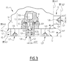
- the applicator 10 comprises a body 14 which supports the nozzles 12 and which constitutes a rigid structural element allowing the nozzles 12 to be positioned in space.
- the body 14 is in one piece.
- the body 14 is parallelepiped 14 and defines a front face 142, a rear face 143 parallel to the front face 142, two longitudinal faces 144 and 145 parallel to each other and two transverse faces 146 and 147 parallel to each other.
- the front and rear faces 142 and 143 are perpendicular to the longitudinal faces 144 and 145, on the one hand, and to the transverse faces 146 and 147 on the other hand.
- the longitudinal faces 144 and 145 are, moreover, perpendicular to the transverse faces 146 and 147.
- the faces 144 to 147 are adjacent to the face 142.
- the front face 142 of the body 14 is turned towards an object to be coated when the applicator 10 works, to make the main part of a pattern, by applying a coating product to an object O.
- the nozzles 12 are rigidly mounted on the body 14. More precisely, four rows of sixteen nozzles 12 are arranged on the front face 142 of the body 14, these nozzles projecting from this front face which is flat.
- each nozzle 12 belongs to a printing head 13 which further comprises a control member 132, for example of the piezoelectric component type, and a rod 134.
- Each nozzle 12 comprises a needle 122 controlled by the control member 132 from printhead 13 to which the nozzle belongs to. Needle 122 is connected to component 132 by rod 134.
- the paint to be applied flows into a channel 16 formed in the body 14 and circulates, from one nozzle 12 to the other, in the direction of the arrows F2.
- the channel 16 constitutes a common means of supplying various nozzles 12 located on the face 142 of the applicator 10.
- 121 is the part of a nozzle 12 which projects from a face of the body 14. Inside the part 121 of a nozzle, a seat 124 is provided against which the needle 122 of the nozzle selectively comes. in support, being controlled by component 132.
- An outlet channel 126 is formed in each nozzle 12, downstream of its needle 122 and of its seat 124. This outlet channel opens outwardly, opposite the needle 122, through an ejection orifice 127 formed in a front face 128 of the nozzle 12, more precisely in the front face 128 of its part 121.
- each nozzle 12 constitutes a printing nozzle intended to selectively eject paint through its ejection orifice 127.
- the diameter of the outlet channel 126 of a nozzle 126 and d127 is denoted by d126 the diameter of the ejection orifice 127 of this nozzle.
- d126 the diameter of the ejection orifice 127 of this nozzle.
- the diameter d127 is between 50 micrometers ( ⁇ m) and 500 ⁇ m, preferably between 100 and 200 ⁇ m, more preferably of the order of 150 ⁇ m.
- each nozzle 12 is capable of discharging from its ejection orifice 127, a succession of droplets G.
- these droplets G are shown as all leaving the printing nozzles 12 at the same time, which does not correspond to the method described below but makes it possible to identify the flow paths of these nozzles.
- ⁇ 142 the main plane of the front face 142 which is plane.
- ⁇ 127 the plane in which are arranged the ejection orifices 127 of the nozzles 12 arranged on the front face 142.
- the planes ⁇ 142 and ⁇ 127 are parallel and the orifices 127 are themselves distributed on the front face 142, in the vicinity of this one.
- the transverse surface 147 is equipped with four nozzles 12 identical to those mounted on the front face 142, which constitute a row of printing nozzles and which also protrude from this surface 147, which is flat and of which we denote ⁇ 147 the main shot.
- the ejection orifices 127 of the nozzles 12 mounted on the surface 147 extend in a plane ⁇ '127 parallel to the plane ⁇ 147 and can be considered to be equally distributed on the surface 147, in the vicinity thereof.
- ⁇ 146 the transverse surface 146 which is flat and of which the main plane is denoted ⁇ 146.
- the ejection orifices of these nozzles 12 extend in a plane ⁇ "127 parallel to the plane ⁇ 146. These orifices can be considered to be equally distributed over the surface 146, in the vicinity thereof.
- the planes ⁇ 142 and ⁇ 147, on the one hand, ⁇ 142 and ⁇ 146, on the other hand, are not parallel to each other.
- the outlet orifices 127 of the nozzles respectively provided on the faces 142, 146 and 147 extend in at least two non-parallel dimensions.
- the applicator 10 can be qualified as a multi-nozzle-multi-dimension (MBMD) head. It constitutes a coating product applicator which enables such a product to be applied with a high degree of precision, as is apparent from the following explanations.
- MBMD multi-nozzle-multi-dimension
- ⁇ a defined angle, inside the body 14, 10 between the planes ⁇ 142 and ⁇ 147.
- this angle ⁇ is equal to 90 °.
- this angle ⁇ may be between 30 ° and 150 °, preferably between 60 and 90 °. Preferred values of this angle are 60 °, 90 ° and 120 °.
- the angle ⁇ is also the angle between the planes ⁇ 127 and ⁇ '127, measured on the side of these planes facing the body 14.
- the nozzles arranged 12 on the faces 142 and 147 which respectively eject paint perpendicular to the planes ⁇ 127 and ⁇ '127, make it possible to eject paint in two directions not parallel.
- the situation is the same for the printing nozzles 12 respectively located on the faces 142 and 146.
- the applicator 10 When it is appropriate to create a strip B by forming patterns on the roof of a motor vehicle body O, the applicator 10 is brought by the multi-axis robot 20 above the area of the roof to be coated, then the applicator 10 is moved parallel to the longitudinal axis of the body, which is in practice parallel to the axis X2, as represented by arrows F4 and F4 'at the figure 4 .
- the nozzles 12 arranged on the front face 142 of the body 14 are activated.
- the needles 122 of these nozzles 12 are moved away from their seats 124 by the actuators 132 and the rods 134 of the printing heads 13. corresponding.
- the outlet channels 126 of these nozzles are supplied with paint and paint is ejected through their respective ejection orifices 127, which are in the plane ⁇ 127, in the direction of the roof of the body O, as represented by the droplets G which flow in the direction of arrows F42 at the figure 4 .
- This printing technique makes it possible to constitute, on the roof of the vehicle, a strip B, the longitudinal edges of which, parallel to the direction of movement of the applicator according to the arrows F4 and F4 ', are well defined and rectilinear.
- a first step consists in making the band B by moving the applicator 10 in the direction of the arrows F4 and F4 'at the figure 4 , while supplying the nozzles 12, the ejection orifices 127 of which are located in the plane ⁇ 127.
- the robot 20 brings the transverse face 147 of the applicator 10 facing the rear edge of the roof of the body and moves this applicator 10 perpendicular to the axis X2, in the arrows F5 and F5 'at the figure 5 , while activating the nozzles 12 mounted on this transverse face 147, which has the effect of discharging droplets G of paint towards the edge of the roof from the ejection orifices 127 of these nozzles located in the plane ⁇ '127 , in the direction of arrow F52 at the figure 5 .
- This makes it possible to constitute, at the rear end of the strip B, a clean transverse border without indentations.
- An operation of the same type is then carried out, in the same second step of the method, at the level of the front edge of the border B, by activating the four nozzles 12 arranged on the transverse face 146 of the body 14, which eject paint through. their ejection orifices 127 located in the plane ⁇ "127.
- the order of implementation of the sub-steps of the second step, consisting of creating the front and rear transverse borders of the strip B, can be reversed.
- the production of a transverse border can be carried out only at the front or only at the rear of the strip B.
- the application distance that is to say the distance measured between the ejection orifices 127 of the active printing nozzles 12 and the surface of the roof of the object O being coating, is advantageously between 5 and 50 mm. This makes it possible to increase the paint transfer rate and to reduce the distance of the overspray, that is to say of the diffuse paint cloud, compared to the imprint of the main spray, that is to say -to say of the cloud of paint directed to the principal on the bodywork. This ensures that the uncontrolled drops G of paint are deposited as close as possible to the coverage area of the main spray, and therefore drops under control, intended to constitute the B band.
- the nozzles 12 are completely integrated inside the body 14 of the applicator 10.
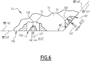
- the front surfaces 128 of the nozzles 12, in which the ejection orifices 127 are formed are afferent with the lateral faces of the body 14, in particular the front 142 and transverse 147 faces shown in figure 6 .
- the planes ⁇ 142 and ⁇ 127 are the same, as are the planes ⁇ 147 and ⁇ '127.
- the planes ⁇ 142 and ⁇ 147 are not parallel, as are the planes ⁇ 127, ⁇ '127.
- the nozzles 12 respectively arranged on the surfaces 142 and 147 make it possible to eject paint in two non-parallel directions.
- the angle ⁇ defined as in the first embodiment is equal to 120 °.
- the printing nozzles 12 arranged on the face 142 are identical to each other and the printing nozzles 12 arranged on the face 147 are identical to each other, but the diameter d127 of the ejection orifices 127 of the nozzles printing 12 disposed on the surface 142 have a first value, while the diameter of 127 of the orifices 127 of the nozzles 12 disposed on the surface 147 has a second value, less than the first value.
- the ejection orifices 127 of the nozzles 12 disposed on the transverse face 147 are thinner than the ejection holes 127 of the nozzles 12 disposed on the front face 142.
- the printing nozzles 12 arranged on the different faces of the body 14 are used at different times during the implementation of a coating product application process. This is why provision is made for the printing nozzles, the ejection orifices of which are distributed over two distinct faces of the body 14, to be activated independently of one another, when the applicator 10 is in operation.
- a common paint circulation channel or channels 16 is provided to supply the nozzles 12 mounted on the surface 142, while another comparable channel is provided to supply the nozzles. 12 provided on the face 146 and that yet another comparable channel is provided to supply the nozzles 12 provided on the face 147.
- the supply of paint to these different channels is regulated by valves, preferably integrated into the body 14, controlled. independently of each other.
- the different actuators 132 of the print heads 13 including the different nozzles 12 can be controlled independently of each other.
- a decorative hood strip can be made with a width of 100mm over a length of 1m, which corresponds to an area of 0.1m 2 , while coating an entire roof amounts to covering an area of approximately 2mx2m, i.e. 4m 2 .
- Applicator 10 could therefore be selected depending on the intended use.
- the applicator 10 can be equipped with an interface 18 provided on its rear face 143 and allowing its rapid assembly / disassembly at the end of the arm 22 of the robot 20.
- This interface enables a connection to be made. fluidic and electrical of the applicator 10 with the robot 20.
- the interface 10 can operate with a magnetic clipping system or by any other suitable method.
- each applicator 10 is designed to apply paint with a flow rate belonging to a range of flow rates, therefore designed to coat a surface area included in a range of areas, during the time allocated to implement the method of the invention. . this allows the robot 20 to load the applicator 10 best suited to the pattern to be produced on the vehicle body entering its work zone.
- the applicator 10 is described in the case where printing nozzles 12 are provided on three faces of the body 14, namely the faces 142, 146 and 147.
- the nozzles 12 can be provided on only two of these faces or, on the contrary, on four, five or six of these faces, it being specified here that, preferably, the rear face 143 is not equipped with nozzles 12.
- the invention is described above in the case of the application of paint to a motor vehicle body. It is particularly suitable for the application of paint of the "base coat" type, that is to say a layer of color with or without an effect, as well as for the application of mono or two-component varnishes.
- the application of a primer is also possible.
- the applicator 10 can be used to apply ink or any other coating material.
- a static mixer is integrated into the installation I, more precisely inside the body 14, on the path of the channel 16 , just upstream of nozzles 12.
- an additional guide air can be brought to the level of the front face 128 of each nozzle 12 in order to contain the drops G coming out of the ejection orifices 127.
- This additional guide air can be ejected. in the form of an air gap, i.e. an air curtain acting as a border that cannot be crossed by the droplets G, an air ring or several air jets shaped with a vortex shape, converging or diverging in the direction of the axis of the outlet channel 126 of each nozzle.
- This additional guide air can be brought to the vicinity of nozzles 12 individually or for a group of nozzles, for example, a row of nozzles, a column of nozzles or a matrix of nozzles, or even in a grouped fashion for all the nozzles arranged. on one face of the body 14 the applicator 10.
- a system for electrostatic charging of the applied coating product can be provided, this system being internally charged and / or externally charged, which makes it possible to accelerate the drops G emerging from the ejection orifices 127 and deposit them on the surface to be coated which is connected to ground.
- Such an electrostatic system can be provided individually for each nozzle 12, for a group of nozzles, for example per row, per column or for a matrix of nozzles or under. the form of a single electrostatic system provided for all the nozzles of the applicator 10.
- nozzles 12 indicated above and shown in the figures are indicative. Alternatively, they can be different.
- several printing nozzles 12 are provided on a first face of the body 14, for example the face 142, to be used during the first step of the process. These nozzles are preferably arranged in rows and columns.
- One or more nozzles are provided on another face, for example face 146 or 147, for the second step.
- the number of nozzles provided on the first face of the body 14 is different, in practice greater than the number of nozzles provided on the other face.
- the body 14 of the applicator 10 can be supported by a device other than a multi-axis robot, provided that this device makes it possible to implement the two steps of the method of the invention.
- a cross table can be used for an application on parallelepipedic objects
- the installation I comprises several applicators 10.
- the body 14 may have a shape other than a parallelepiped.
- the body 14 can be formed of several parts assembled in a rigid manner, that is to say without the possibility of relative movement between them.
- the main planes ⁇ 142, ⁇ 146 and ⁇ 147 are defined as mean planes of these faces, as are the planes ⁇ 127, ⁇ '127 and ⁇ "127. This is particularly the case if the applicator is used to apply a paint or a varnish to door frames or contours, which may have a section having several sides connected by shelves which can be painted at the same time.
- the invention is described above during its implementation for the creation of a strip. However, it is applicable for the creation of other patterns on any object to be coated.
Landscapes
- Engineering & Computer Science (AREA)
- Robotics (AREA)
- Mechanical Engineering (AREA)
- Manufacturing & Machinery (AREA)
- Coating Apparatus (AREA)
- Application Of Or Painting With Fluid Materials (AREA)
- Spray Control Apparatus (AREA)
Priority Applications (1)
| Application Number | Priority Date | Filing Date | Title |
|---|---|---|---|
| EP22213986.7A EP4169622B1 (de) | 2019-04-19 | 2020-04-17 | Beschichtungsmittelapplikator, applikationsanlage mit einem solchen applikator und verfahren zum auftragen mit einem solchen applikator |
Applications Claiming Priority (1)
| Application Number | Priority Date | Filing Date | Title |
|---|---|---|---|
| FR1904218A FR3095132B1 (fr) | 2019-04-19 | 2019-04-19 | Applicateur de produit de revêtement, installation d’application comprenant un tel applicateur et procédé d’application au moyen d’un tel applicateur |
Related Child Applications (2)
| Application Number | Title | Priority Date | Filing Date |
|---|---|---|---|
| EP22213986.7A Division EP4169622B1 (de) | 2019-04-19 | 2020-04-17 | Beschichtungsmittelapplikator, applikationsanlage mit einem solchen applikator und verfahren zum auftragen mit einem solchen applikator |
| EP22213986.7A Division-Into EP4169622B1 (de) | 2019-04-19 | 2020-04-17 | Beschichtungsmittelapplikator, applikationsanlage mit einem solchen applikator und verfahren zum auftragen mit einem solchen applikator |
Publications (2)
| Publication Number | Publication Date |
|---|---|
| EP3725419A1 true EP3725419A1 (de) | 2020-10-21 |
| EP3725419B1 EP3725419B1 (de) | 2024-03-13 |
Family
ID=67810827
Family Applications (2)
| Application Number | Title | Priority Date | Filing Date |
|---|---|---|---|
| EP20170084.6A Active EP3725419B1 (de) | 2019-04-19 | 2020-04-17 | Applikator für beschichtungsmittel, auftragsanlage, die einen solchen applikator umfasst, und auftragsverfahren mithilfe dieses applikators |
| EP22213986.7A Active EP4169622B1 (de) | 2019-04-19 | 2020-04-17 | Beschichtungsmittelapplikator, applikationsanlage mit einem solchen applikator und verfahren zum auftragen mit einem solchen applikator |
Family Applications After (1)
| Application Number | Title | Priority Date | Filing Date |
|---|---|---|---|
| EP22213986.7A Active EP4169622B1 (de) | 2019-04-19 | 2020-04-17 | Beschichtungsmittelapplikator, applikationsanlage mit einem solchen applikator und verfahren zum auftragen mit einem solchen applikator |
Country Status (7)
| Country | Link |
|---|---|
| US (1) | US11731158B2 (de) |
| EP (2) | EP3725419B1 (de) |
| JP (1) | JP2020175384A (de) |
| KR (1) | KR20200123012A (de) |
| CN (1) | CN111822233B (de) |
| FR (1) | FR3095132B1 (de) |
| RU (1) | RU2020113771A (de) |
Cited By (1)
| Publication number | Priority date | Publication date | Assignee | Title |
|---|---|---|---|---|
| EP4023344A4 (de) * | 2019-08-30 | 2023-08-23 | Kyocera Corporation | Lackiervorrichtung, lackierter film und lackierverfahren |
Families Citing this family (5)
| Publication number | Priority date | Publication date | Assignee | Title |
|---|---|---|---|---|
| CN113492086B (zh) * | 2021-05-12 | 2021-12-24 | 广州信邦智能装备股份有限公司 | 一种汽车前后挡风玻璃自动涂胶机涂胶的方法 |
| CN113510054B (zh) * | 2021-06-22 | 2022-12-02 | 机械工业第九设计研究院股份有限公司 | 一种多胶品集成涂胶机器人系统 |
| CN113492082A (zh) * | 2021-06-30 | 2021-10-12 | 镭德杰标识科技武汉有限公司 | 喷涂装置、赋码系统及涂层喷涂方法 |
| DE102021121060A1 (de) | 2021-08-13 | 2023-02-16 | Bayerische Motoren Werke Aktiengesellschaft | Applikationskopf, Applikationsvorrichtung sowie Fahrzeugteil |
| JP2023140457A (ja) * | 2022-03-23 | 2023-10-05 | 株式会社リコー | 液体吐出システム |
Citations (5)
| Publication number | Priority date | Publication date | Assignee | Title |
|---|---|---|---|---|
| EP1884365A1 (de) | 2006-07-28 | 2008-02-06 | Abb Research Ltd. | Farbauftragegerät und Beschichtungsverfahren |
| EP2139656A2 (de) * | 2007-04-17 | 2010-01-06 | Gruppo Barbieri & Tarozzi S.p.A. | Dekorierungsverfahren und -system zum dekorieren von keramischen produkten |
| WO2010046064A1 (de) * | 2008-10-24 | 2010-04-29 | Dürr Systems GmbH | Beschichtungseinrichtung und zugehöriges beschichtungsverfahren |
| WO2015036235A1 (en) * | 2013-09-12 | 2015-03-19 | Agfa Graphics Nv | Large cuboid shaped object inkjet printing |
| EP3292914A1 (de) * | 2016-09-12 | 2018-03-14 | The Boeing Company | Endeffektor für druckkopf mit variablem durchmesser |
Family Cites Families (10)
| Publication number | Priority date | Publication date | Assignee | Title |
|---|---|---|---|---|
| KR100468811B1 (ko) * | 2000-06-26 | 2005-01-29 | 에이비비 가부시키가이샤 | 투톤 도장방법 |
| JP3754632B2 (ja) * | 2000-06-26 | 2006-03-15 | Abb株式会社 | ツートーン塗装方法 |
| JP2003251813A (ja) * | 2002-03-06 | 2003-09-09 | Ricoh Co Ltd | インクジェットヘッド、インクジェット記録装置及び積層型圧電素子 |
| JP2007230849A (ja) * | 2006-03-03 | 2007-09-13 | Nippon Sheet Glass Co Ltd | ガラス板端部の塗布方法、ガラス板端部の塗布装置、及びそのガラス板端部の塗布方法により端部が被覆されたガラス板 |
| WO2009088864A1 (en) * | 2007-12-31 | 2009-07-16 | Exatec, Llc | Apparatus and method for printing three-dimensional articles |
| CN102449806B (zh) * | 2009-06-04 | 2014-06-25 | E.I.内穆尔杜邦公司 | 多色电子器件及通过印刷来形成该器件的方法 |
| CN101954327A (zh) * | 2009-07-14 | 2011-01-26 | 鸿富锦精密工业(深圳)有限公司 | 立体喷墨头 |
| KR20160055917A (ko) | 2013-09-16 | 2016-05-18 | 바스프 에스이 | 식기세척 세제에서의 개질된 폴리아스파르트산의 용도 |
| FR3060420B1 (fr) | 2016-12-15 | 2024-01-05 | Exel Ind | Tete d'application d'un produit de revetement sur une surface a revetir et systeme d'application comprenant cette tete d'application |
| DE102019102088A1 (de) * | 2018-01-30 | 2019-08-01 | Ford Global Technologies, Llc | Verbundstoffultraschallmaterialapplikatoren mit einzeln ansteuerbaren mikroapplikatoren und verfahren der verwendung von diesen |
-
2019
- 2019-04-19 FR FR1904218A patent/FR3095132B1/fr active Active
-
2020
- 2020-04-13 JP JP2020071510A patent/JP2020175384A/ja active Pending
- 2020-04-13 CN CN202010286889.XA patent/CN111822233B/zh active Active
- 2020-04-14 KR KR1020200045266A patent/KR20200123012A/ko active Search and Examination
- 2020-04-17 EP EP20170084.6A patent/EP3725419B1/de active Active
- 2020-04-17 US US16/851,927 patent/US11731158B2/en active Active
- 2020-04-17 RU RU2020113771A patent/RU2020113771A/ru unknown
- 2020-04-17 EP EP22213986.7A patent/EP4169622B1/de active Active
Patent Citations (5)
| Publication number | Priority date | Publication date | Assignee | Title |
|---|---|---|---|---|
| EP1884365A1 (de) | 2006-07-28 | 2008-02-06 | Abb Research Ltd. | Farbauftragegerät und Beschichtungsverfahren |
| EP2139656A2 (de) * | 2007-04-17 | 2010-01-06 | Gruppo Barbieri & Tarozzi S.p.A. | Dekorierungsverfahren und -system zum dekorieren von keramischen produkten |
| WO2010046064A1 (de) * | 2008-10-24 | 2010-04-29 | Dürr Systems GmbH | Beschichtungseinrichtung und zugehöriges beschichtungsverfahren |
| WO2015036235A1 (en) * | 2013-09-12 | 2015-03-19 | Agfa Graphics Nv | Large cuboid shaped object inkjet printing |
| EP3292914A1 (de) * | 2016-09-12 | 2018-03-14 | The Boeing Company | Endeffektor für druckkopf mit variablem durchmesser |
Cited By (1)
| Publication number | Priority date | Publication date | Assignee | Title |
|---|---|---|---|---|
| EP4023344A4 (de) * | 2019-08-30 | 2023-08-23 | Kyocera Corporation | Lackiervorrichtung, lackierter film und lackierverfahren |
Also Published As
| Publication number | Publication date |
|---|---|
| US20200331023A1 (en) | 2020-10-22 |
| EP4169622A1 (de) | 2023-04-26 |
| CN111822233A (zh) | 2020-10-27 |
| US11731158B2 (en) | 2023-08-22 |
| EP4169622B1 (de) | 2024-03-13 |
| CN111822233B (zh) | 2023-07-28 |
| KR20200123012A (ko) | 2020-10-28 |
| FR3095132A1 (fr) | 2020-10-23 |
| RU2020113771A (ru) | 2021-10-18 |
| EP3725419B1 (de) | 2024-03-13 |
| FR3095132B1 (fr) | 2021-05-07 |
| JP2020175384A (ja) | 2020-10-29 |
Similar Documents
| Publication | Publication Date | Title |
|---|---|---|
| EP3725419B1 (de) | Applikator für beschichtungsmittel, auftragsanlage, die einen solchen applikator umfasst, und auftragsverfahren mithilfe dieses applikators | |
| EP3335801B1 (de) | Kopf zum autragen eines beschichtungsprodukts auf eine zu beschichtende oberfläche, und auftragsvorrichtung, die einen solchen auftragskopf umfasst | |
| EP3213823B1 (de) | Beschichtungsvorrichtung, mehrachsiger roboter mit einer solchen beschichtungsvorrichtung sowie entsprechendes beschichtungsverfahren | |
| EP1303359B1 (de) | Verfahren und station zum wechseln von flüssigkeit für eine spritzanlage | |
| EP3519260B1 (de) | Reinigungsvorrichtung zum aufsprühen mindestens einer flüssigkeit auf eine zu reinigende oberfläche eines kraftfahrzeugs | |
| EP3810429B1 (de) | Vorrichtung zum bedrucken oder beschichten von oberflächen dreidimensionaler teile | |
| FR2945461A1 (fr) | Projecteur et organe de pulverisation de produit de revetement et procede de projection mettant en oeuvre un tel projecteur. | |
| EP3643409A1 (de) | Beschichtungsverfahren nach der drop-on-demand-technologie, und applikationsroboter für die umsetzung dieses verfahrens | |
| EP3269454B2 (de) | Lenkluftring mit mindestens drei serien von verschiedenen luftausstossdüsen, drehzerstäuber für ein beschichtungsprodukt mit einer solchem ring, und beschcichtungsverfahren | |
| EP3033180A1 (de) | Zerstäuber für ein flüssigbeschichtungsprodukt und sprühanlage mit solch einem zerstäuber | |
| EP3725421B1 (de) | Anlage zum auftragen eines beschichtungsmittels und reinigungsverfahren einer solchen anlage | |
| EP3995315A1 (de) | Verfahren und anlage zur aufbringung eines beschichtungsprodukts auf eine oberfläche | |
| WO2020089242A1 (fr) | Bol de pulvérisation de produit de revêtement, projecteur rotatif incluant un tel bol et procédé de nettoyage d'un tel projecteur | |
| FR3087705A1 (fr) | Impression a jet d'encre sur une surface complexe | |
| EP3012109A1 (de) | Gesamtheit eines objekts mit griff und einer tintenstrahlmaschine zum bedrucken dieses objekts | |
| FR3008004A1 (fr) | Procede et installation de traitement d'une surface d'un objet en polymere | |
| JP6990644B2 (ja) | 塗料の塗布方法及び塗装装置 | |
| FR3062595A1 (fr) | Procede d'impression d'une piece transparente ou translucide et piece obtenue | |
| FR3085619A1 (fr) | Procede d'impression par jet d'encre d'un motif sur une surface en matiere plastique | |
| WO2019229309A1 (fr) | Modele perdu pour moulage d'une piece metallique comprenant une plaque metallique de recouvrement | |
| WO2018109307A1 (fr) | Applicateur de peinture comprenant plusieurs coupelles |
Legal Events
| Date | Code | Title | Description |
|---|---|---|---|
| PUAI | Public reference made under article 153(3) epc to a published international application that has entered the european phase |
Free format text: ORIGINAL CODE: 0009012 |
|
| STAA | Information on the status of an ep patent application or granted ep patent |
Free format text: STATUS: THE APPLICATION HAS BEEN PUBLISHED |
|
| AK | Designated contracting states |
Kind code of ref document: A1 Designated state(s): AL AT BE BG CH CY CZ DE DK EE ES FI FR GB GR HR HU IE IS IT LI LT LU LV MC MK MT NL NO PL PT RO RS SE SI SK SM TR |
|
| AX | Request for extension of the european patent |
Extension state: BA ME |
|
| STAA | Information on the status of an ep patent application or granted ep patent |
Free format text: STATUS: REQUEST FOR EXAMINATION WAS MADE |
|
| 17P | Request for examination filed |
Effective date: 20210326 |
|
| RBV | Designated contracting states (corrected) |
Designated state(s): AL AT BE BG CH CY CZ DE DK EE ES FI FR GB GR HR HU IE IS IT LI LT LU LV MC MK MT NL NO PL PT RO RS SE SI SK SM TR |
|
| STAA | Information on the status of an ep patent application or granted ep patent |
Free format text: STATUS: EXAMINATION IS IN PROGRESS |
|
| 17Q | First examination report despatched |
Effective date: 20220202 |
|
| GRAP | Despatch of communication of intention to grant a patent |
Free format text: ORIGINAL CODE: EPIDOSNIGR1 |
|
| STAA | Information on the status of an ep patent application or granted ep patent |
Free format text: STATUS: GRANT OF PATENT IS INTENDED |
|
| RIC1 | Information provided on ipc code assigned before grant |
Ipc: B05B 13/04 20060101ALN20221208BHEP Ipc: B05B 15/65 20180101ALN20221208BHEP Ipc: B05B 1/08 20060101ALN20221208BHEP Ipc: B05B 7/04 20060101ALN20221208BHEP Ipc: B05B 12/18 20180101ALN20221208BHEP Ipc: B25J 9/00 20060101ALI20221208BHEP Ipc: B41J 3/407 20060101ALI20221208BHEP Ipc: B05B 12/04 20060101AFI20221208BHEP |
|
| RIC1 | Information provided on ipc code assigned before grant |
Ipc: B05B 13/04 20060101ALN20221215BHEP Ipc: B05B 15/65 20180101ALN20221215BHEP Ipc: B05B 1/08 20060101ALN20221215BHEP Ipc: B05B 7/04 20060101ALN20221215BHEP Ipc: B05B 12/18 20180101ALN20221215BHEP Ipc: B25J 9/00 20060101ALI20221215BHEP Ipc: B41J 3/407 20060101ALI20221215BHEP Ipc: B05B 12/04 20060101AFI20221215BHEP |
|
| INTG | Intention to grant announced |
Effective date: 20230105 |
|
| RIN1 | Information on inventor provided before grant (corrected) |
Inventor name: MEDARD, CYRILLE Inventor name: CHOUAN, NICOLAS |
|
| GRAJ | Information related to disapproval of communication of intention to grant by the applicant or resumption of examination proceedings by the epo deleted |
Free format text: ORIGINAL CODE: EPIDOSDIGR1 |
|
| STAA | Information on the status of an ep patent application or granted ep patent |
Free format text: STATUS: EXAMINATION IS IN PROGRESS |
|
| INTC | Intention to grant announced (deleted) | ||
| GRAP | Despatch of communication of intention to grant a patent |
Free format text: ORIGINAL CODE: EPIDOSNIGR1 |
|
| STAA | Information on the status of an ep patent application or granted ep patent |
Free format text: STATUS: GRANT OF PATENT IS INTENDED |
|
| RIC1 | Information provided on ipc code assigned before grant |
Ipc: B05B 13/04 20060101ALN20230914BHEP Ipc: B05B 15/65 20180101ALN20230914BHEP Ipc: B05B 1/08 20060101ALN20230914BHEP Ipc: B05B 7/04 20060101ALN20230914BHEP Ipc: B05B 12/18 20180101ALN20230914BHEP Ipc: B25J 9/00 20060101ALI20230914BHEP Ipc: B41J 3/407 20060101ALI20230914BHEP Ipc: B05B 12/04 20060101AFI20230914BHEP |
|
| RIC1 | Information provided on ipc code assigned before grant |
Ipc: B05B 13/04 20060101ALN20230920BHEP Ipc: B05B 15/65 20180101ALN20230920BHEP Ipc: B05B 1/08 20060101ALN20230920BHEP Ipc: B05B 7/04 20060101ALN20230920BHEP Ipc: B05B 12/18 20180101ALN20230920BHEP Ipc: B25J 9/00 20060101ALI20230920BHEP Ipc: B41J 3/407 20060101ALI20230920BHEP Ipc: B05B 12/04 20060101AFI20230920BHEP |
|
| INTG | Intention to grant announced |
Effective date: 20231018 |
|
| GRAS | Grant fee paid |
Free format text: ORIGINAL CODE: EPIDOSNIGR3 |
|
| GRAA | (expected) grant |
Free format text: ORIGINAL CODE: 0009210 |
|
| STAA | Information on the status of an ep patent application or granted ep patent |
Free format text: STATUS: THE PATENT HAS BEEN GRANTED |
|
| AK | Designated contracting states |
Kind code of ref document: B1 Designated state(s): AL AT BE BG CH CY CZ DE DK EE ES FI FR GB GR HR HU IE IS IT LI LT LU LV MC MK MT NL NO PL PT RO RS SE SI SK SM TR |
|
| REG | Reference to a national code |
Ref country code: GB Ref legal event code: FG4D Free format text: NOT ENGLISH |
|
| REG | Reference to a national code |
Ref country code: CH Ref legal event code: EP |
|
| REG | Reference to a national code |
Ref country code: DE Ref legal event code: R096 Ref document number: 602020027053 Country of ref document: DE |
|
| REG | Reference to a national code |
Ref country code: IE Ref legal event code: FG4D Free format text: LANGUAGE OF EP DOCUMENT: FRENCH |