EP3213823B1 - Beschichtungsvorrichtung, mehrachsiger roboter mit einer solchen beschichtungsvorrichtung sowie entsprechendes beschichtungsverfahren - Google Patents
Beschichtungsvorrichtung, mehrachsiger roboter mit einer solchen beschichtungsvorrichtung sowie entsprechendes beschichtungsverfahren Download PDFInfo
- Publication number
- EP3213823B1 EP3213823B1 EP17159049.0A EP17159049A EP3213823B1 EP 3213823 B1 EP3213823 B1 EP 3213823B1 EP 17159049 A EP17159049 A EP 17159049A EP 3213823 B1 EP3213823 B1 EP 3213823B1
- Authority
- EP
- European Patent Office
- Prior art keywords
- applicator
- nozzles
- distance
- nozzle
- coating product
- Prior art date
- Legal status (The legal status is an assumption and is not a legal conclusion. Google has not performed a legal analysis and makes no representation as to the accuracy of the status listed.)
- Active
Links
- 238000000576 coating method Methods 0.000 title claims description 123
- 239000011248 coating agent Substances 0.000 title claims description 122
- 238000000034 method Methods 0.000 claims description 27
- 230000005484 gravity Effects 0.000 claims description 12
- 239000007921 spray Substances 0.000 claims description 10
- 230000005284 excitation Effects 0.000 claims description 7
- 238000005507 spraying Methods 0.000 claims description 2
- 238000012544 monitoring process Methods 0.000 claims 2
- 239000010410 layer Substances 0.000 description 24
- 239000000463 material Substances 0.000 description 19
- 238000006073 displacement reaction Methods 0.000 description 18
- 230000006870 function Effects 0.000 description 7
- 239000003973 paint Substances 0.000 description 7
- 230000000694 effects Effects 0.000 description 6
- 230000007547 defect Effects 0.000 description 5
- 230000001447 compensatory effect Effects 0.000 description 3
- 239000012530 fluid Substances 0.000 description 3
- 238000011084 recovery Methods 0.000 description 3
- 238000005259 measurement Methods 0.000 description 2
- 239000000853 adhesive Substances 0.000 description 1
- 230000001070 adhesive effect Effects 0.000 description 1
- 239000011247 coating layer Substances 0.000 description 1
- 239000003086 colorant Substances 0.000 description 1
- 230000002950 deficient Effects 0.000 description 1
- 238000010586 diagram Methods 0.000 description 1
- 238000001035 drying Methods 0.000 description 1
- 238000005516 engineering process Methods 0.000 description 1
- 230000007257 malfunction Effects 0.000 description 1
- 230000003287 optical effect Effects 0.000 description 1
- 238000007789 sealing Methods 0.000 description 1
- 230000035945 sensitivity Effects 0.000 description 1
- 238000011144 upstream manufacturing Methods 0.000 description 1
- 239000002966 varnish Substances 0.000 description 1
Images


Classifications
-
- B—PERFORMING OPERATIONS; TRANSPORTING
- B05—SPRAYING OR ATOMISING IN GENERAL; APPLYING FLUENT MATERIALS TO SURFACES, IN GENERAL
- B05B—SPRAYING APPARATUS; ATOMISING APPARATUS; NOZZLES
- B05B12/00—Arrangements for controlling delivery; Arrangements for controlling the spray area
- B05B12/08—Arrangements for controlling delivery; Arrangements for controlling the spray area responsive to condition of liquid or other fluent material to be discharged, of ambient medium or of target ; responsive to condition of spray devices or of supply means, e.g. pipes, pumps or their drive means
- B05B12/12—Arrangements for controlling delivery; Arrangements for controlling the spray area responsive to condition of liquid or other fluent material to be discharged, of ambient medium or of target ; responsive to condition of spray devices or of supply means, e.g. pipes, pumps or their drive means responsive to conditions of ambient medium or target, e.g. humidity, temperature position or movement of the target relative to the spray apparatus
- B05B12/124—Arrangements for controlling delivery; Arrangements for controlling the spray area responsive to condition of liquid or other fluent material to be discharged, of ambient medium or of target ; responsive to condition of spray devices or of supply means, e.g. pipes, pumps or their drive means responsive to conditions of ambient medium or target, e.g. humidity, temperature position or movement of the target relative to the spray apparatus responsive to distance between spray apparatus and target
-
- B—PERFORMING OPERATIONS; TRANSPORTING
- B05—SPRAYING OR ATOMISING IN GENERAL; APPLYING FLUENT MATERIALS TO SURFACES, IN GENERAL
- B05B—SPRAYING APPARATUS; ATOMISING APPARATUS; NOZZLES
- B05B1/00—Nozzles, spray heads or other outlets, with or without auxiliary devices such as valves, heating means
- B05B1/02—Nozzles, spray heads or other outlets, with or without auxiliary devices such as valves, heating means designed to produce a jet, spray, or other discharge of particular shape or nature, e.g. in single drops, or having an outlet of particular shape
-
- B—PERFORMING OPERATIONS; TRANSPORTING
- B05—SPRAYING OR ATOMISING IN GENERAL; APPLYING FLUENT MATERIALS TO SURFACES, IN GENERAL
- B05B—SPRAYING APPARATUS; ATOMISING APPARATUS; NOZZLES
- B05B12/00—Arrangements for controlling delivery; Arrangements for controlling the spray area
- B05B12/02—Arrangements for controlling delivery; Arrangements for controlling the spray area for controlling time, or sequence, of delivery
- B05B12/04—Arrangements for controlling delivery; Arrangements for controlling the spray area for controlling time, or sequence, of delivery for sequential operation or multiple outlets
-
- B—PERFORMING OPERATIONS; TRANSPORTING
- B05—SPRAYING OR ATOMISING IN GENERAL; APPLYING FLUENT MATERIALS TO SURFACES, IN GENERAL
- B05B—SPRAYING APPARATUS; ATOMISING APPARATUS; NOZZLES
- B05B12/00—Arrangements for controlling delivery; Arrangements for controlling the spray area
- B05B12/08—Arrangements for controlling delivery; Arrangements for controlling the spray area responsive to condition of liquid or other fluent material to be discharged, of ambient medium or of target ; responsive to condition of spray devices or of supply means, e.g. pipes, pumps or their drive means
- B05B12/084—Arrangements for controlling delivery; Arrangements for controlling the spray area responsive to condition of liquid or other fluent material to be discharged, of ambient medium or of target ; responsive to condition of spray devices or of supply means, e.g. pipes, pumps or their drive means responsive to condition of liquid or other fluent material already sprayed on the target, e.g. coating thickness, weight or pattern
-
- B—PERFORMING OPERATIONS; TRANSPORTING
- B05—SPRAYING OR ATOMISING IN GENERAL; APPLYING FLUENT MATERIALS TO SURFACES, IN GENERAL
- B05B—SPRAYING APPARATUS; ATOMISING APPARATUS; NOZZLES
- B05B13/00—Machines or plants for applying liquids or other fluent materials to surfaces of objects or other work by spraying, not covered by groups B05B1/00 - B05B11/00
- B05B13/02—Means for supporting work; Arrangement or mounting of spray heads; Adaptation or arrangement of means for feeding work
- B05B13/04—Means for supporting work; Arrangement or mounting of spray heads; Adaptation or arrangement of means for feeding work the spray heads being moved during spraying operation
- B05B13/0447—Installation or apparatus for applying liquid or other fluent material to conveyed separate articles
- B05B13/0452—Installation or apparatus for applying liquid or other fluent material to conveyed separate articles the conveyed articles being vehicle bodies
-
- B—PERFORMING OPERATIONS; TRANSPORTING
- B05—SPRAYING OR ATOMISING IN GENERAL; APPLYING FLUENT MATERIALS TO SURFACES, IN GENERAL
- B05B—SPRAYING APPARATUS; ATOMISING APPARATUS; NOZZLES
- B05B17/00—Apparatus for spraying or atomising liquids or other fluent materials, not covered by the preceding groups
- B05B17/04—Apparatus for spraying or atomising liquids or other fluent materials, not covered by the preceding groups operating with special methods
- B05B17/06—Apparatus for spraying or atomising liquids or other fluent materials, not covered by the preceding groups operating with special methods using ultrasonic or other kinds of vibrations
- B05B17/0607—Apparatus for spraying or atomising liquids or other fluent materials, not covered by the preceding groups operating with special methods using ultrasonic or other kinds of vibrations generated by electrical means, e.g. piezoelectric transducers
- B05B17/0653—Details
-
- B—PERFORMING OPERATIONS; TRANSPORTING
- B05—SPRAYING OR ATOMISING IN GENERAL; APPLYING FLUENT MATERIALS TO SURFACES, IN GENERAL
- B05D—PROCESSES FOR APPLYING FLUENT MATERIALS TO SURFACES, IN GENERAL
- B05D1/00—Processes for applying liquids or other fluent materials
- B05D1/02—Processes for applying liquids or other fluent materials performed by spraying
-
- B—PERFORMING OPERATIONS; TRANSPORTING
- B05—SPRAYING OR ATOMISING IN GENERAL; APPLYING FLUENT MATERIALS TO SURFACES, IN GENERAL
- B05D—PROCESSES FOR APPLYING FLUENT MATERIALS TO SURFACES, IN GENERAL
- B05D7/00—Processes, other than flocking, specially adapted for applying liquids or other fluent materials to particular surfaces or for applying particular liquids or other fluent materials
- B05D7/14—Processes, other than flocking, specially adapted for applying liquids or other fluent materials to particular surfaces or for applying particular liquids or other fluent materials to metal, e.g. car bodies
-
- B—PERFORMING OPERATIONS; TRANSPORTING
- B05—SPRAYING OR ATOMISING IN GENERAL; APPLYING FLUENT MATERIALS TO SURFACES, IN GENERAL
- B05D—PROCESSES FOR APPLYING FLUENT MATERIALS TO SURFACES, IN GENERAL
- B05D7/00—Processes, other than flocking, specially adapted for applying liquids or other fluent materials to particular surfaces or for applying particular liquids or other fluent materials
- B05D7/50—Multilayers
- B05D7/52—Two layers
- B05D7/54—No clear coat specified
-
- B—PERFORMING OPERATIONS; TRANSPORTING
- B25—HAND TOOLS; PORTABLE POWER-DRIVEN TOOLS; MANIPULATORS
- B25J—MANIPULATORS; CHAMBERS PROVIDED WITH MANIPULATION DEVICES
- B25J11/00—Manipulators not otherwise provided for
- B25J11/0075—Manipulators for painting or coating
-
- B—PERFORMING OPERATIONS; TRANSPORTING
- B41—PRINTING; LINING MACHINES; TYPEWRITERS; STAMPS
- B41J—TYPEWRITERS; SELECTIVE PRINTING MECHANISMS, i.e. MECHANISMS PRINTING OTHERWISE THAN FROM A FORME; CORRECTION OF TYPOGRAPHICAL ERRORS
- B41J3/00—Typewriters or selective printing or marking mechanisms characterised by the purpose for which they are constructed
- B41J3/407—Typewriters or selective printing or marking mechanisms characterised by the purpose for which they are constructed for marking on special material
- B41J3/4073—Printing on three-dimensional objects not being in sheet or web form, e.g. spherical or cubic objects
-
- B—PERFORMING OPERATIONS; TRANSPORTING
- B05—SPRAYING OR ATOMISING IN GENERAL; APPLYING FLUENT MATERIALS TO SURFACES, IN GENERAL
- B05B—SPRAYING APPARATUS; ATOMISING APPARATUS; NOZZLES
- B05B1/00—Nozzles, spray heads or other outlets, with or without auxiliary devices such as valves, heating means
- B05B1/14—Nozzles, spray heads or other outlets, with or without auxiliary devices such as valves, heating means with multiple outlet openings; with strainers in or outside the outlet opening
-
- B—PERFORMING OPERATIONS; TRANSPORTING
- B05—SPRAYING OR ATOMISING IN GENERAL; APPLYING FLUENT MATERIALS TO SURFACES, IN GENERAL
- B05B—SPRAYING APPARATUS; ATOMISING APPARATUS; NOZZLES
- B05B12/00—Arrangements for controlling delivery; Arrangements for controlling the spray area
- B05B12/08—Arrangements for controlling delivery; Arrangements for controlling the spray area responsive to condition of liquid or other fluent material to be discharged, of ambient medium or of target ; responsive to condition of spray devices or of supply means, e.g. pipes, pumps or their drive means
- B05B12/12—Arrangements for controlling delivery; Arrangements for controlling the spray area responsive to condition of liquid or other fluent material to be discharged, of ambient medium or of target ; responsive to condition of spray devices or of supply means, e.g. pipes, pumps or their drive means responsive to conditions of ambient medium or target, e.g. humidity, temperature position or movement of the target relative to the spray apparatus
- B05B12/122—Arrangements for controlling delivery; Arrangements for controlling the spray area responsive to condition of liquid or other fluent material to be discharged, of ambient medium or of target ; responsive to condition of spray devices or of supply means, e.g. pipes, pumps or their drive means responsive to conditions of ambient medium or target, e.g. humidity, temperature position or movement of the target relative to the spray apparatus responsive to presence or shape of target
-
- B—PERFORMING OPERATIONS; TRANSPORTING
- B05—SPRAYING OR ATOMISING IN GENERAL; APPLYING FLUENT MATERIALS TO SURFACES, IN GENERAL
- B05B—SPRAYING APPARATUS; ATOMISING APPARATUS; NOZZLES
- B05B13/00—Machines or plants for applying liquids or other fluent materials to surfaces of objects or other work by spraying, not covered by groups B05B1/00 - B05B11/00
- B05B13/02—Means for supporting work; Arrangement or mounting of spray heads; Adaptation or arrangement of means for feeding work
- B05B13/04—Means for supporting work; Arrangement or mounting of spray heads; Adaptation or arrangement of means for feeding work the spray heads being moved during spraying operation
- B05B13/0431—Means for supporting work; Arrangement or mounting of spray heads; Adaptation or arrangement of means for feeding work the spray heads being moved during spraying operation with spray heads moved by robots or articulated arms, e.g. for applying liquid or other fluent material to 3D-surfaces
-
- B—PERFORMING OPERATIONS; TRANSPORTING
- B05—SPRAYING OR ATOMISING IN GENERAL; APPLYING FLUENT MATERIALS TO SURFACES, IN GENERAL
- B05C—APPARATUS FOR APPLYING FLUENT MATERIALS TO SURFACES, IN GENERAL
- B05C11/00—Component parts, details or accessories not specifically provided for in groups B05C1/00 - B05C9/00
- B05C11/10—Storage, supply or control of liquid or other fluent material; Recovery of excess liquid or other fluent material
- B05C11/1002—Means for controlling supply, i.e. flow or pressure, of liquid or other fluent material to the applying apparatus, e.g. valves
- B05C11/1015—Means for controlling supply, i.e. flow or pressure, of liquid or other fluent material to the applying apparatus, e.g. valves responsive to a conditions of ambient medium or target, e.g. humidity, temperature ; responsive to position or movement of the coating head relative to the target
- B05C11/1018—Means for controlling supply, i.e. flow or pressure, of liquid or other fluent material to the applying apparatus, e.g. valves responsive to a conditions of ambient medium or target, e.g. humidity, temperature ; responsive to position or movement of the coating head relative to the target responsive to distance of target
-
- B—PERFORMING OPERATIONS; TRANSPORTING
- B05—SPRAYING OR ATOMISING IN GENERAL; APPLYING FLUENT MATERIALS TO SURFACES, IN GENERAL
- B05C—APPARATUS FOR APPLYING FLUENT MATERIALS TO SURFACES, IN GENERAL
- B05C5/00—Apparatus in which liquid or other fluent material is projected, poured or allowed to flow on to the surface of the work
- B05C5/02—Apparatus in which liquid or other fluent material is projected, poured or allowed to flow on to the surface of the work the liquid or other fluent material being discharged through an outlet orifice by pressure, e.g. from an outlet device in contact or almost in contact, with the work
- B05C5/0291—Apparatus in which liquid or other fluent material is projected, poured or allowed to flow on to the surface of the work the liquid or other fluent material being discharged through an outlet orifice by pressure, e.g. from an outlet device in contact or almost in contact, with the work the material being discharged on the work through discrete orifices as discrete droplets, beads or strips that coalesce on the work or are spread on the work so as to form a continuous coating
-
- B—PERFORMING OPERATIONS; TRANSPORTING
- B05—SPRAYING OR ATOMISING IN GENERAL; APPLYING FLUENT MATERIALS TO SURFACES, IN GENERAL
- B05D—PROCESSES FOR APPLYING FLUENT MATERIALS TO SURFACES, IN GENERAL
- B05D1/00—Processes for applying liquids or other fluent materials
- B05D1/28—Processes for applying liquids or other fluent materials performed by transfer from the surfaces of elements carrying the liquid or other fluent material, e.g. brushes, pads, rollers
Definitions
- the invention relates to a coating product applicator, a multi-axis robot provided with this applicator and a method of applying a coating product to the surface of a workpiece, such as the hood of a motor vehicle.
- the method according to the invention makes it possible to apply two layers of coating product with a perfect junction between the two layers.
- EP1892107 A1 discloses an applicator of a coating product of the prior art.
- car manufacturers offer their customers cars whose body paint can be customized.
- the body can be multicolored, with different patterns, such as bands.
- a known technique is to apply a mask on the rest of the body to expose only the surface of the cover corresponding to a band being applied.
- this mask is made with adhesive paper that is removed once the pattern created.
- this technique is relatively difficult because it requires manually applying a mask on the body of each vehicle.
- a multiaxis robot comprising a movable arm on which is mounted a specific applicator.
- This applicator is an ink jet type printhead in English, which comprises at least one row of nozzles through which the coating product flows.
- a strip of paint with sharp edges can then be applied by moving the robot arm in a direction perpendicular to the row of nozzles of the print head.
- the robot must make several round trips with trajectories programmed so that the bands are contiguous, that is to say so that there is no non-overlap area between two passes of the print head.
- a disadvantage of this technology is that the junction is not perfect when the coating is applied to curved surfaces, such as the hood of a car. Non-overlapping zones are then observed between two passages of the applicator.
- the invention more particularly intends to remedy by proposing a coating product applicator making it possible to obtain a perfect connection between two strips coming from two successive passages, even on a curved surface, such as the hood of a car.
- the invention relates to an applicator of a coating product on a surface to be coated, comprising at least one row of nozzles, among which at least the first nozzle of the row comprises a valve.
- the applicator further comprises at least one distance sensor, for measuring an application distance of the first nozzle at an advanced point with respect thereto over a path of the applicator, and an electronic control unit of the valve, which is programmed to collect the distance measured by the distance sensor, and, depending on the value of the collected distance, to open or close the valve.
- Each nozzle of the row comprises a valve, while the distance sensor is able to measure the distance of application of at least some nozzles of the row to points respectively advanced relative to them in the path of the applicator .
- the distance sensor is a laser sensor, comprising a cell emitting a laser beam and a receiver cell of a reflected laser beam, while the distance sensor is able to scan with its beam a line perpendicular to the direction of travel. the applicator, so as to measure the application distance of at least some nozzles of the row at points advanced relative thereto in the path of the applicator.
- the invention also relates to a multi-axis robot, comprising a mobile arm on which is mounted an applicator as defined above.
- step b) comprises substeps of measuring at least an application distance of the first nozzle at an advanced point with respect thereto on a path of the applicator, and depending on the measured application distance, to open or close the valve.
- the robot follows its set path, the distance measured by the distance sensor at an advanced point relative to the first nozzle in the path of the applicator is substantially less than a value of reference, which corresponds to the distance of application of the nozzles when there is no coating product.
- a value of reference which corresponds to the distance of application of the nozzles when there is no coating product.
- the distance measured by the sensor at an advanced point relative to the first nozzle in the path of the applicator is substantially equal to the reference value.
- the valve of the first nozzle is open. The first nozzle then covers the surface when it reaches the advanced point in the path of the applicator. This makes it possible to avoid areas of non-overlap and to obtain a perfect junction between the two layers of coating product.
- the valve of the first nozzle is therefore controlled dynamically, that is to say in real time, in the path of the applicator.
- This dynamic adjustment makes it possible to apply a strip of coating product with a perfect junction with respect to another existing strip, even on a curved surface such as the surface of a car hood.
- the junction between two strips of paint is therefore ensured by the dynamic control of the valve, without using an ultra-precise robot or an advanced trajectory controller.
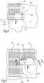
- a multiaxis robot 2 comprising a movable arm 4 on which is mounted an applicator 6 coating product.
- the applicator 6 is a ink jet print head in English.
- the coating product considered is paint, but it can also be a primer, an ink or a varnish.
- the multiaxis robot 2 is disposed on the side of a conveyor 10 moving bodies 8 of a motor vehicle.
- the multiaxis robot 2 is designed to apply a strip of paint B on the surface S of the cover of each bodywork 8 moved by the conveyor 10.
- the robot 2 comprises a controller, not shown, programmed to control the arm 4 of way to perform a set path.
- the coating product applicator 6 comprises a row of nozzles, referenced 60.1 to 60.i in the figures, i being the number of nozzles in the row, which is greater than or equal to 2 and for example between 10 and 100.
- the nozzles 60.1 to 60.i of the row are arranged perpendicular to the direction of movement of the applicator 6 during the application of the coating product.
- the nozzles 60.1 to 60.i are configured to deposit the coating product drop by drop. Once deposited, the drop spreads over the surface to be coated.
- a spreading coefficient is defined as the ratio between the area of the coated surface after the spread drop and the diameter of the drop. This coefficient of spread depends in particular on the type of coating product used. It is between 5 and 10, often of the order of 7.
- the nozzles may be shaped to form a continuous net of coating material.
- the nozzles 60.1 to 60.i are holes in a plate, the width of the drops or the net then corresponding to the width of the holes.
- each nozzle 60.1 to 60.i of the row comprises a valve, respectively 66.1 to 66.i.
- the valves 66.1 to 66.i of the applicator 6 are each connected to a common reservoir 64 of coating product.
- the valves 66.2 to 66.i are optional for carrying out the invention.
- valves 66.1 to 66.i are electrically operated valves, in particular piezoelectric valves.
- Piezoelectric valves are so-called exciter valves, comprising a deformable piezoelectric element under the application of electrical excitation. This type of valve works as follows. When the piezoelectric element is not excited, the fluid remains inside the reservoir 64 because the atmospheric pressure is greater than the pressure of the reservoir. On the other hand, when the piezoelectric element is excited, for example with an alternating voltage, it then locally generates an overpressure allowing the fluid to flow out of the tank.
- the flow of coating material ejected through the nozzles 60.1 to 60.i can be adjusted by acting on the excitation frequency of the respective valves 66.1 to 66.i. We then speak of proportional valves.
- a valve is defined as any device for controlling the flow of the coating product.
- the valves 66.1 to 66.i are so-called shutter valves, which operate by selective sealing of the fluid passage conduit.
- another type of exciter valve may be envisaged to equip the applicator 6. It may be a valve with an excitation of thermal, acoustic, pneumatic or electrostatic type.
- the applicator 6 comprises distance sensors 62.1 to 62.i which are positioned at points advanced with respect to the nozzles 60.1 to 60.i in the path of the applicator 6.
- the sensors 62.1 to 62.i are arranged in the form row, which is parallel to the row of nozzles 60.1 to 60.i.
- the applicator 6 has as many distance sensors 62.1 to 62.i as nozzles 60.1 to 60.i.
- Each sensor 62.1 to 62.i is therefore associated with a nozzle.
- the sensor 62.1 is associated with the nozzle 60.1.
- the position of the sensors 62.1 to 62.i along the path of the applicator 6 at a time t corresponds to that of the nozzles 60.1 to 60.i at time t + ⁇ t, where ⁇ t is a duration which depends on the speed of displacement of the applicator 6 and the distance d6 between the nozzle row 60.1 to 60.i and the row of sensors 32.1 to 62.i, measured parallel to the direction of movement of the applicator 6.
- the sensors distance 62.2 to 62.i are optional for carrying out the invention.
- the distance sensors 62.1 to 62.i measure, at each instant t, the distance between the applicator 6 and the portion of the surface to be coated S which lies opposite them. Now, at time t + ⁇ t, the nozzles 62.1 to 62.i reach the position of the sensors 60.1 to 60.i at time t. The distance measured by the sensors 62.1 to 62.i at the instant t therefore corresponds respectively to the distance of application of the nozzles 60.1 to 60.i at the instant t + ⁇ t, that is to say at the distance between the nozzles and the part to be coated, measured in a direction parallel to a projection axis of the coating product through the nozzles. Each distance sensor 62.1 to 62.i thus measures the distance of application of the nozzle with which it is associated with a point, in the path of the applicator 6, which is advanced relative to the nozzle 60.1 to 60.i associated with it.
- each distance sensor 62.1 to 62.i is a laser sensor, comprising a cell emitting a laser beam and a receiver cell of a reflected laser beam, on the surface S.
- the laser beam emitted by the emitting cell is substantially parallel to the axis of projection of the coating product through the nozzles 60.1 to 60.i.
- the accuracy of each sensor is less than 10 microns, in particular of the order of 1 micron.
- the applicator 6 further comprises an electronic control unit 68.
- the electronic control unit 68 controls the opening and closing of each of the valves 66.1 to 66.i. To do this, the unit 68 sends to each of the valves 66.1 to 66.i control signals, among which the electrical control signal S1 of the valve 66.1 is shown schematically in FIG. figure 4 . Depending on the signal received, valve 66.1 opens or closes.
- Each distance sensor 62.1 to 62.i is connected to the unit 68.
- the electronic control unit 68 can therefore collect the distance measured by the sensors at each instant t.
- the electronic control unit 68 is able to compare the distance measured by each of the sensors 62.1 to 62.i with a reference value D.
- This reference value D corresponds to the distance between the nozzles 60.1 to 60.i and the surface to coat S when it is not coated with coating material. In other words, the reference value D corresponds to the application distance of the nozzles 60.1 to 60.i.
- this reference value D is a predetermined value which is identical for all the nozzles 60.1 to 60.i.
- it is a constant value in time, that is to say that the same distance d1 is used regardless of the position of the applicator 6 on its path.
- the distance d1 can then be prerecorded in memory in the electronic control unit 68.
- the reference value D is specific to each nozzle and / or is not a function that is constant in time, that is to say that this reference value D varies according to the position of the nozzle. applicator 6 on its way.
- This variant is advantageous when the surface to be coated is left, that is to say when the application distance varies substantially from one nozzle to another and / or varies substantially in the path of the applicator 6.
- the distance D at which the distance transmitted by the sensors is compared at each instant can be acquired by learning, by moving the applicator 6 a first time "blank", that is to say without applying any product. coating.
- the values acquired by the sensors 62.1 to 62.i during the training then serve as reference distances, in the same way as the reference value D.
- a method of applying a coating B to a surface to be coated S is described below in connection with the Figures 2 to 5 .
- This process is performed by the applicator 6 described above.
- the surface S to be coated is the hood of a car 8.
- the coating B visible at the figure 1 is formed by two layers B1 and B2 of coating product.
- the product layers B1 and B2 are bands extending in the longitudinal direction of the hood.
- the bands B1 and B2 are applied contiguously, that is to say so that there is no non-overlap zone between the bands B1 and B2.
- the figure 2 illustrates a step a) during which the applicator 6 makes a first pass to apply a first band B1 to the surface to be coated S.
- the direction of movement of the applicator 6 is shown in FIG. figure 2 by an arrow A1.
- the displacement direction A1 corresponds in fact to the director vector of the displacement line of the applicator 6. This vector is at each moment parallel to the surface to be coated.
- the line of displacement of the applicator is a straight line.
- the line of displacement of the applicator is a curve, with a radius of curvature substantially equal to that of the curved surface.
- the figure 3 illustrates a step b) during which the applicator 6 makes a second pass to apply a second band B2 contiguously to the first band B1.
- the direction of displacement of the applicator 6 during this second passage which is represented in FIG. figure 3 by an arrow A2 is substantially parallel to the direction of movement A1 of the applicator during the first pass.
- the line of displacement of the applicator 6 during the first pass is a first curve
- the line of displacement of the applicator during the second pass is a second curve parallel to the first curve.
- Any plane normal to a curve among the first and the second curve is then also a plane normal to the other, the distance between two respective points of the two curves which are contained in this normal plane being substantially constant.
- the applicator 6 is moved, during step b), as to partially cover the first band B1, that is to say as to cover the edge B1.1 of the first band B1 intended to be joined with the second band B2. This forces the recovery. This is particularly visible at figure 3 , where it can be seen that the applicator 6 projects slightly over the first band B1. If all the valves 66.1 to 66.i were open during the second passage of the applicator 6, the first band B1 would then be covered over a certain width.
- the covering width corresponds approximately to the width of the surface covered by a droplet from the first nozzle once it has spread. Alternatively, the covering width may be the surface covered after spreading by several nozzles, including four or five successive nozzles. In practice, the width of recovery depends on several parameters related to the imprecision of the robot, the phenomenon of "tubing", the problems of repeatability or the tolerances of the jets.
- the lap width is approximately 1 mm to 5 mm.
- the distance sensor 62.1 measures, at a time t, the distance that separates it from the surface to be coated S. As explained above, this measured distance corresponds to the application distance of the nozzle 60.1 at time t + ⁇ t. In sub-step b1), the distance sensor 62.1 thus measures the distance of application of the nozzle 30.1 at a point advanced with respect thereto in the path of the applicator 6.
- the electronic control unit 68 then collects the distance measured by the sensor 62.1 and compares, during a substep b2) this distance with the reference value D.
- An application area of a nozzle is defined as a portion of the surface to be coated to be coated with coating material by the nozzle.
- the zone of application of a nozzle is not the zone that the nozzle is capable of coating at time t, but the zone that the nozzle will be capable of coating at the same time. instant t + ⁇ t on the trajectory of the applicator 6.
- the distance measured by the distance sensor 62.1 at an advanced point relative to the first nozzle 60.1 in the path of the applicator is substantially less than the reference value D.
- the valve 66.1 of the first nozzle 60.1 is then closed during a sub-step b3) of the process of the invention and no coating product is applied by the first nozzle 60.1 when it reaches the advanced point, it that is, at time t + ⁇ t. This avoids an extra thickness at the junction between the two strips B1 and B2.
- the electronic control unit 68 considers that the value measured by a sensor is substantially lower than the reference value D when the difference between the two values, representing the actual thickness of the coating product. deposited on the surface S, is less than 50% of the theoretical wet thickness.
- the wet theoretical thickness corresponds to the thickness of the coating product on the surface S that it is desired to deposit before drying.
- the electronic control unit 68 may consider that the value measured by the sensor is substantially less than the reference value D when the difference between the two values is less than 20 ⁇ m.
- step b) the robot deviates from its set path, the distance measured in step b1) by the distance sensor 62.1 at an advanced point relative to the first nozzle 60.1 on the path the applicator 6 is substantially equal to the reference value D.
- the application area of the first nozzle 60.1 at an advanced point in the path of the applicator 6 is not coated with coating product.
- the valve 66.1 of the first nozzle 60.1 is open. The first nozzle then covers the surface S when it reaches the advanced point in the path of the applicator, that is to say at time t + ⁇ t. This makes it possible to avoid areas of non-overlap between the strips B1 and B2 and to obtain a perfect junction between the two layers of coating product B1 and B2.
- the zone Z1 for applying the nozzle 60.1 is covered by the band B1 applied during the first passage of the applicator 6.
- the laser beam F2 emitted by the sensor 62.1 is reflected by the coating strip B1 in a beam laser F'2, which is received by the receiver cell of the sensor 62.1.
- the time elapsed between the emission of the laser beam and the reception of the reflected laser beam is representative of the distance d2 between the sensor 62.1 and the coating layer B1.
- the sensor 62.1 communicates the distance d2 to the unit 68, which compares it with the reference value D.
- the distance d2 being smaller than the distance D, the electronic control unit 68 closes the valve 66.1 of the nozzle 60.1, as symbolized at the figure 4 by a cross.
- the laser beam F1 emitted by the other sensors 62.2 to 62.i is reflected in a laser beam F'1 directly by the surface S to be coated.
- the distance d1 measured by the sensors 62.2 to 62.i thus corresponds substantially to the reference value D mentioned above.
- the electronic control unit 68 therefore does not close the valves 66.2 to 66.i corresponding, as symbolized by the drops of product to the figure 4 .
- the second band B2 therefore has a width smaller than that of the first band B1.
- the distance sensors 62.1 to 62.i measure, at each instant t, the application distance of each of the nozzles 60.1 to 60.i at time t + ⁇ t.
- the electronic control unit 68 compares each of the values measured by the sensors 62.1 to 62.i with the reference value D.
- the electronic control unit 68 then closes all the valves for which the distance measured by the corresponding sensors is lower than the reference value D and opens the other valves, that is to say all the valves for which the distance measured by the corresponding sensors is substantially equal to the reference value D.
- the applicator 6 includes only one distance sensor 62, which is disposed on the side of the first nozzle 60.1.
- This distance sensor 62 differs from the distance sensors 62.1 to 62.i in that it is able to scan with its laser beam a line extending in a plane perpendicular to the direction of movement of the applicator 6.
- scanning angle ⁇ of the sensor 62 is such that the distance sensor 62 is able to determine the distance profile of the nozzles 60.1 to 60.i, that is to say to measure the distance of application of several successive nozzles. advanced points with respect thereto on the path of the applicator 6.
- the scanning angle ⁇ of the sensor 62 is such that the distance sensor 62 is able to measure the distance of application of each of the nozzles 60.1 to 60.i at points advanced with respect thereto on the path of the applicator 6.
- the scanning angle ⁇ of the sensor 62 may be between 10 ° and 120 °, preferably of the order of 90 °.
- the method of applying the coating product by means of the applicator 6 according to this second embodiment differs from the method described above in connection with the embodiment of the Figures 1 to 5 on the following points.
- the distance sensor 62 measures the distance of application of each of the nozzles 60.1 to 60.i at points advanced with respect thereto in the path A2 of the applicator 6.
- L electronic control unit 68 then collects these values from the sensor 62.
- the electronic control unit 68 Based on the distances measured by the distance sensor 62, the electronic control unit 68 establishes a surface profile over all or part of the application width of the applicator 6, and therefore a thickness profile of the coating. applied on the surface.
- the surface profile of the part corresponds to the intersection between the surface S to be coated in a plane perpendicular to the direction of movement of the applicator 6. What is known as a surface profile is therefore in reality a line.
- this thickness profile corresponds approximately to a step function with a step value corresponding to the thickness of the coating.
- layer of coating material B1 applied to the surface The electronic control unit is able, by analyzing the distance values measured by the sensor 62, to determine the position of the edge B1.1 of the first band B1 along the surface profile.
- the surface is flat, so that the surface profile can be likened to a line XX 'perpendicular to the direction of movement of the applicator 6 and perpendicular to a spray axis of the nozzles 60.1 to 60. i. We are talking about a thick front.
- the position of the edge B1.1 corresponds to the position of the point from which a net variation in distance measured by the sensor 62 is observed, this variation being due to the presence of the layer of coating material B1.
- the sensitivity of the distance sensor 62 is such that the electronic control unit is able to detect the thickness front regardless of the surface geometry to be coated, that is to say even for a left surface. Indeed, the accuracy of the sensor 62 is less than 10 microns, in particular of the order of 1 micron.
- the electronic control unit 68 closes all the valves which are arranged on a first side of the edge B1.1 and opens the valves which are arranged on the second side of the edge B1.1.
- the first side of the edge B1.1 corresponds to the side where the surface S is coated with product to the left of the edge B1.1 to the figure 7
- the second side of the edge B1.1 corresponds to the side where the surface S is devoid of coating product, to the right of the edge B1.1 to the figure 7 .
- the electronic control unit 68 closes the Nozzle valves 60.1 and 60.2 and opens the other valves.
- the coating product is therefore deposited at the locations of the surface S which are not covered by the band B1. It is thus possible to compensate for a defect of trajectory of the robot and to ensure a perfect junction between the two strips B1 and B2, without extra thickness.
- the applicator 6 comprises controllable flow valves 66.1 to 66.i, or proportional valves.
- the valves 66.1 to 66.i are piezoelectric valves whose excitation frequency can be adjusted according to the desired flow rate.
- valves 66.1 to 66.i are shutter type solenoid valves.
- the flow of the valves is then controlled by adjusting the opening frequency of the valves.
- the electronic control unit 68 establishes a thickness profile of the coating material layer in a plane perpendicular to the direction of movement of the applicator and controls the flow rate of the valves 66.1 to 66.i as a function of the thickness of the layer measured at each point of application of the nozzles. More precisely, the thickness of the layer is compared at each point with the theoretical thickness of the layer of coating product, this theoretical thickness being stored in the electronic control unit.
- the flow rate of the corresponding valve corresponds to 100% of the maximum flow rate.
- the thickness calculated by the unit 68 at a point is between 25% and 50% of the theoretical thickness, the flow rate of the corresponding valve corresponds to 75% of the maximum flow rate.
- the thickness calculated by the unit 68 at a point is between 50% and 75% of the theoretical thickness, the flow rate of the corresponding valve corresponds to 50% of the maximum flow rate.
- the corresponding valve is closed.
- the applicator 6 according to the third embodiment has the advantage that if the edge B1.1 of the band B1 is not a clean edge, for example because of the spreading of the coating product, the flow of the valves belonging to nozzles arranged to apply coating product on the edge B1.1 is controlled to overcome the lack of thickness at the junction.
- the applicator 6 Figures 9 to 11 differs from that of the first embodiment by the programming of the electronic control unit 68.
- This particular programming unit 68 aims to avoid wasting the coating product by applying the product of coating in the vacuum.
- This programming is advantageous in the case where the applicator 6 is used to paint a surface defining the edge of a room, such as a longitudinal edge of the roof of a car.
- the applicator 6 is oriented so that the first nozzle 60.1 is the nozzle of the row closest to the edge S.1 of the surface to be coated S.
- the applicator 6 is moved along the edge of the part to be coated, as represented by the arrow A3 at the figure 9 .
- the sensor 62.1 associated with the first nozzle 60.1 measures, at each instant t, the distance that separates it from the first object on which the beam F3 that it emits is reflected. For this, it evaluates the time between the emission of the laser beam F3 and the reception of the reflected laser beam F'3. This distance corresponds to the application distance of the first nozzle 60.1 at a time t + ⁇ t.
- this distance is substantially greater than the reference value D, it means that, at time t + ⁇ t, the part to be coated will not be in the field of application of the nozzle 60.1.
- the electronic control unit 68 then closes the valve 66.1 of the first nozzle 60.1 so as not to apply coating material through the nozzle 60.1 at time t + ⁇ t and thus avoid wasting coating product.
- the sensors 62.2 to 62.i and the valves 66.2 to 66.i are also optional for the embodiment of the invention.
- the distance sensors 62.1 to 62.i dynamically measure the application distance of each of the nozzles 60.1 to 60.i at an advanced point on the path of the applicator 6.
- the robot 2 therefore determines, in real time if the distance measured by each of the sensors 62.1 to 62.i is greater than the reference value D.
- the electronic control unit 68 then closes all the valves for which the distance measured by the corresponding sensors substantially exceeds the reference value D and open the other valves, that is to say all the valves for which the distance measured by the corresponding sensors is substantially equal to the reference value D.
- each of the valves 66.1 to 66.i as a function of the distances measured by their respective sensors makes it possible to apply a coating product on very left surfaces, such as the surface S Figures 9 and 10 , which delimits a curvilinear edge S.1, while moving the applicator 6 in a straight line without losing any coating product.
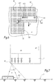
- the applicator 6 of the figure 12 differs from that of the first embodiment in that it comprises, in addition, a second row of distance sensors, respectively referenced 63.1 to 63.i, which are arranged perpendicular to the displacement A4 of the applicator 6.
- the sensors 63.1 to 63.i are thickness measuring sensors arranged late relative to the nozzles 60.1 to 60.i in the path of the applicator 6.
- the position of the nozzles 60.1 to 60.i at time t corresponds to the position of the sensors 63.1 to 63.i at time t + ⁇ t ', where ⁇ t' is a duration which depends on the speed of movement of the applicator 6 and the distance d6 'between the row of nozzles 60.1 at 60.i and the row of sensors 62.1 to 62.i, measured parallel to the direction of movement of the applicator 6.
- the duration ⁇ t' is equal to the duration ⁇ t. Otherwise, the duration ⁇ t and ⁇ t 'are different.
- the distance sensors 63.1 to 63.i are identical to the distance sensors 62.1 to 62.i and make it possible to measure the thickness of the film of coating product applied by the applicator 6.
- the distance applicator 63.1 to 63.i transmits the distance it measures to the electronic control unit 68, which compares the measured distances with the reference value D to determine the thickness of the coating product film applied to the surface S.
- the sensors 63.1 to 63.i thus make it possible to control the uniformity of the thickness of the film deposited by the applicator 6.
- the applicator 6 can make a new passage to standardize the thickness of the coating product applied to the surface S.
- the applicator 6 comprises only one thickness measurement sensor, comparable to the distance sensor 62.
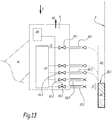
- the applicator of the figure 13 is designed to compensate for the effect of gravity g on product drops ejected through the nozzles 60.1 to 60.i.
- the effect of the gravity g is negligible on the direction of the drops of coating product ejected through the nozzles 60.1 to 60.i.
- the print head 6 is inclined at 90 °, as shown in FIG. figure 13 , the drops of coating material are deflected, under the effect of gravity g, relative to the spray axis of the nozzles, which is horizontal in the example. The deflection of the drops can lead to defects in coverage and / or areas of excess thickness.
- the applicator 6 is repositioned when the surface S to be coated is vertical or inclined.
- This repositioning step consists of moving the applicator 6 with a certain amplitude and in a direction A5 parallel to an axis of the nozzle row 60.1 to 60.i to compensate for the deviation of the coating product due to gravity g.
- the direction A5 of this compensatory displacement is oriented upwards. It is also perpendicular to the direction of movement of the applicator which, in the example of the figure 13 , is perpendicular to the plane of the figure 13 .
- the amplitude of displacement of the applicator 6 during the repositioning step is calculated dynamically as a function of the inclination of the applicator 6 with respect to the ground, the distance of application of the nozzles 60.1-60.i, the speed of ejection of the product through the nozzles and the size of the drops of coating product, it being understood that the size of the drops corresponds to the size of the nozzles 60.1 to 60.i. All these parameters are stored in memory in the controller of robot 2, which is not shown in the figures.
- the inclination value of the applicator 6 relative to the ground is updated automatically according to the orientation of the applicator 6 in the "tool" reference.
- the amplitude of the compensatory displacement, or "offset" in English can also be extracted from a prerecorded abacus, in which are recorded all the displacement values to be applied to compensate the effect of the gravity according to the various influential parameters.
- the repositioning step is performed by the multiaxis robot 2. More precisely, the amplitude of the compensating displacement is calculated by the robot controller, which sends a control signal to the actuator of the robot arm to move the applicator into the robot. the planned direction and with the expected amplitude.
- the electronic control unit 68 is programmed to close the valve of the nozzle or nozzles capable of projecting, because of gravity, the coating product on a zone Z1 of the surface S already coated.
- the applicator 6 moves at an altitude such that the nozzles 60.1 and 60.2 are capable of projecting drops of product on the zone Z1 already covered by the strip B1 of coating product.
- the valves 66.1 and 66.2 are closed.
- the valves to be closed are identified mainly according to the altitude of the applicator 6 relative to the strip B1 of coating product covering a portion of the surface S.
- the altitude of the applicator 6 is a setpoint parameter controlled by the controller of the robot.
- the applicator of the figure 14 is designed to obtain an irreproachable covering, even on a left surface S.
- the applicator 6 of the figure 14 includes proportional valves.
- each nozzle 60.k among the nozzles 60.1 to 60.i is intended to coat a certain portion Sk of the surface S, where k is a natural integer between 1 and i.
- the nozzle 60.2 is intended to coat the portion S2 of the surface S during the displacement of the applicator 6, while the nozzle 60.6 is intended to coat the portion S6 of the surface S.
- these surface portions appear as segments in bold lines.
- the respective portions of the nozzles 60.1 to 60.i are joined.
- the width of the surface portions Sk depends on the width of the nozzles and the coefficient of spreading. When the surface portion Sk is substantially perpendicular to the spray axis of the nozzles, the area of the surface portion Sk substantially corresponds to the area of the coated surface, at a nominal flow rate, once the drop from the 60.k nozzle spread.
- the surface portion Sk is not perpendicular to the spray axis of the nozzles, as is the case, for example, for the surface portion S2 relative to the nozzle 60.2, the area of the coated surface at a nominal flow rate is less than the area of the surface portion Sk to be coated. There is therefore a defect of recovery.
- each nozzle 60.k among the nozzles 60.1 to 60.i is controlled according to the inclination of the respective surface portion Sk with respect to a plane perpendicular to the direction of spray of nozzles 60.1 to 60.i. In the configuration of the figure 14 this plane is horizontal.
- the flow rate applied is all the more important that the portion of the surface to be coated is inclined, so as to compensate for the lack of coating product.
- each surface portion Sk with respect to the plane perpendicular to the spray axis of the nozzles is calculated by the electronic control unit 68 by determining the distance difference ⁇ D k , measured parallel to the spray axis.
- the end points of the surface portion S2 are represented with the references S2.1 and S2.2, the difference between these two points being represented by the measurement ⁇ D 2 corresponding to the difference between the distance D1 and the distance D2.
- the electronic unit 68 therefore compares a distance D1, measured parallel to the spray axis of the nozzles, between the point S2.1 and the distance sensor and a distance D2, measured in parallel. to the spray nozzle axis, between point S2.2 and the distance sensor.
- the flow of coating product flowing through a nozzle 60.k is even higher than the distance difference ⁇ D k is high.
- the relationship between the rate and the distance difference ⁇ D k is a linear type relationship.
- the surface portion S6 intended to be covered by the nozzle 60.6 has a smaller area than the surface portion S2 intended to be covered by the nozzle 60.2.
- the coating product flow applied by the nozzle 60.2 is higher than the coating product flow applied by the nozzle 60.6.
- the applicator 6 comprises several rows of nozzles aligned with each other.
- the applicator 6 further comprises a second row of nozzles disposed downstream of the sensor or sensors 63.1 to 63.i in the path of the applicator 6.
- the second row of nozzles is arranged late relative to each thickness measuring sensor 63.1-63.i on the path A4 of the applicator 6.
- This second row of nozzles also comprises i nozzles, which are distributed identically to the row of nozzles 60.1 to 60.i.
- This second row of nozzles makes it possible to compensate for any lack of overlap, or lack of thickness, detected by the sensor or sensors 63.1 to 63.i and thus to homogenize the thickness of the layer of coating product applied without making any difference. 'back and forth.
- Such a lack of thickness can appear when a nozzle of the first row, that is to say the upstream row of nozzles 60.1 to 60.i, is clogged, or at least has a malfunction.
- a lack of thickness can also appear during the coating of a left surface, as represented in FIG. figure 14 in connection with the seventh embodiment, or during defective covering at the junction between two strips of coating material.
- Another advantage of this variant is that the control of the valves 66.1 to 66.i of the first row of nozzles can be simplified because the covering defects can be corrected almost instantaneously.
- the applicator 6 comprises a single valve 66.1 corresponding to the valve of the first nozzle 60.1 of the row.
- the applicator 6 includes only one sensor 62.1 designed to measure the distance of application of the first nozzle 60.1 at a point advanced with respect thereto in the path of the applicator 6.
- only the first nozzle 60.1 and the last nozzle 60.i of the row comprise a valve, respectively 66.1 and 66.i.
- the applicator comprises only two distance sensors, respectively 62.1 and 62.i, designed to respectively measure the application distance of the first nozzle 60.1 and the last nozzle 60.i at an advanced point on the path of the applicator 6.
- ultrasonic sensors other types of distance sensors may be envisaged, such as ultrasonic sensors.
Landscapes
- Engineering & Computer Science (AREA)
- Life Sciences & Earth Sciences (AREA)
- Wood Science & Technology (AREA)
- Manufacturing & Machinery (AREA)
- Coating Apparatus (AREA)
- Robotics (AREA)
- Mechanical Engineering (AREA)
- Spray Control Apparatus (AREA)
- Application Of Or Painting With Fluid Materials (AREA)
- Length Measuring Devices By Optical Means (AREA)
- Manipulator (AREA)
Claims (15)
- Auftragevorrichtung (6) für ein Beschichtungsprodukt auf eine zu beschichtende Fläche (S), mindestens eine Reihe Düsen (60.1 - 60.i) umfassend, von denen zumindest die erste Düse (60.1) der Reihe ein Ventil (66.1) hat, darüber hinaus umfassend,- mindestens einen Abstandssensor (62; 62.1), um einen Auftrageabstand (d2) der ersten Düse (60.1) zu einem vorausliegenden Punkt (t + Δt) in Bezug auf diejenige auf einer Bahn (A2, A4) der Auftragevorrichtung zu messen, und- eine elektronische Steuereinheit (68) für das Ventil (66.1), die programmiert ist, um die folgenden Schritte auszuführen:derart, dass:i) den vom Abstandssensor gemessenen Abstand (d2) zu erfassen,ii) in Abhängigkeit vom Wert des im Schritt i) erfassten Abstands das Ventil (66.1) zu öffnen oder zu schließen,- jede Düse (60.1 - 60.i) der Reihe ein Ventil (66.1 - 66.i) umfasst,- der Abstandssensor (62) in der Lage ist, den Auftrageabstand zumindest mancher Düsen der Reihe zu jeweils vorausliegenden Punkten in Bezug auf diejenigen auf der Bahn (A2, A4) der Auftragevorrichtung zu messen,wobei die Auftragevorrichtung dadurch gekennzeichnet ist, dass:- der Abstandssensor (62; 62.1 - 62.i) ein Lasersensor ist, der eine Abstrahlzelle (F1, F2, F3) für einen Laserstrahl und eine Empfängerzelle (F'1, F'2, F'3) für einen reflektierten Laserstrahl umfasst, und- der Abstandssensor (62) in der Lage ist, mit seinem Strahl eine zur Verschiebungsrichtung der Auftragevorrichtung senkrechte Linie abzutasten, um den Auftrageabstand zumindest mancher Düsen der Reihe zu vorausliegenden Punkten in Bezug auf diejenigen auf der Bahn (A2, A4) der Auftragevorrichtung zu messen.
- Auftragevorrichtung nach Anspruch 1, dadurch gekennzeichnet, dass die elektronische Steuereinheit (68) dazu programmiert ist, die vom Abstandssensor gemessenen Abstände (d2) zu erfassen, um über die gesamte oder teilweise Auftragebreite der Auftragevorrichtung ein Profil der zu beschichtenden Fläche (S) zu bestimmen, das Flächenprofil zu analysieren, um die Position eines Rands einer Beschichtungsproduktschicht entlang des Profils der Fläche zu erkennen, alle Ventile der Düsen zu öffnen, die auf einer Seite des Rands angeordnet sind, und die Ventile zu schließen, die auf der anderen Seite des Rands entlang des Profils der Fläche angeordnet sind.
- Auftragevorrichtung nach Anspruch 1 oder 2, dadurch gekennzeichnet, dass die Ventile (66.1 - 66.i) Proportionalventile sind, und dass die elektronische Steuereinheit (68) dazu programmiert ist, ein Dickenprofil der Beschichtungsproduktschicht in einer Ebene senkrecht zur Verschiebungsrichtung der Auftragevorrichtung zu erstellen und den Durchsatz der Ventile (66.1 - 66.i) in Abhängigkeit von der an jedem der Auftragepunkte der Düsen (60.1 - 60.i) gemessenen Dicke der Schicht zu kontrollieren.
- Auftragevorrichtung nach einem der vorhergehenden Ansprüche, dadurch gekennzeichnet, dass jedes Ventil (66.1 - 66.i) ein piezoelektrisches Ventil ist, dessen Durchsatz von einer Anregungsfrequenz des Ventils abhängt.
- Auftragevorrichtung nach einem der vorhergehenden Ansprüche, dadurch gekennzeichnet, dass die elektronische Steuereinheit (68) dazu programmiert ist, das Ventil (66.1) der ersten Düse (60.1) zu schließen, wenn der vom Sensor (62.1) gemessene Abstand (d2) wesentlich höher ist als ein Referenzwert (D).
- Auftragevorrichtung nach einem der vorhergehenden Ansprüche, dadurch gekennzeichnet, dass die Auftragevorrichtung darüber hinaus mindestens einen Dickenmesssensor (63.1 - 63.i) umfasst, der dazu konfiguriert ist, jeweils die Dicke des von den Düsen (60.1 - 60.i) aufgetragenen Beschichtungsproduktfilms an zurückliegenden Punkten in Bezug auf diejenigen auf der Bahn der Auftragevorrichtung zu messen.
- Auftragevorrichtung nach Anspruch 6, dadurch gekennzeichnet, dass sie eine weitere Reihe Düsen umfasst, die in Bezug auf jeden Dickenmesssensor (63.1 - 63.i) auf der Bahn (A4) der Auftragevorrichtung (6) dahinterliegend angeordnet ist.
- Mehrachsiger Roboter (2), einen beweglichen Arm (4) umfassend, an dem eine Auftragevorrichtung (6) nach einem der vorhergehenden Ansprüche angebracht ist.
- Verfahren zum Auftragen eines Beschichtungsprodukts (B) auf eine Fläche (S) eines Bauteils (8), wobei dieses Verfahren mittels einer Auftragevorrichtung umgesetzt wird, die mindestens eine Reihe Düsen (60.1: 60.i) umfasst, von denen zumindest die erste Düse (60.1) der Reihe ein Ventil (66.1) hat, wobei das Verfahren Schritte umfasst, die darin bestehen:a) die Auftragevorrichtung (6) in einer ersten Richtung (A1) zu verschieben, um eine erste Beschichtungsproduktschicht (B1) aufzutragen,b) die Auftragevorrichtung (6) in einer zweiten, zur ersten Richtung im Wesentlichen parallelen Richtung (A2) zu verschieben, um eine zweite Beschichtungsproduktschicht (B2) stoffschlüssig an der ersten Schicht (B1) aufzutragen,wobei dieses Verfahren dadurch gekennzeichnet ist, dass der Schritt b) Teilschritte umfasst, die darin bestehen:b1) mindestens einen Auftrageabstand (d2) der ersten Düse (60.1) zu einem vorausliegenden Punkt (t + Δt) in Bezug auf diejenige auf einer Bahn (A2) der Auftragevorrichtung zu messen, undb2) in Abhängigkeit vom gemessenen Auftrageabstand das Ventil (66.1) zu öffnen oder zu schließen.
- Verfahren nach Anspruch 9, dadurch gekennzeichnet, dass
der Teilschritt b1) darin besteht, Auftrageabstände (d1, d2) zumindest mancher der Düsen der Reihe zu jeweils vorausliegenden Punkten in Bezug auf diejenigen auf der Bahn der Auftragevorrichtung zu erfassen, um über die gesamte oder teilweise Auftragebreite der Auftragevorrichtung (6) ein Profil der zu beschichtenden Fläche (S) zu bestimmen, während
der Teilschritt b2) darin besteht, das Flächenprofil zu analysieren, um die Position eines Rands (B1.1) der ersten Schicht (B1) des Beschichtungsprodukts entlang des Profils der Fläche (S) zu erkennen und alle Ventile der Düsen zu öffnen, die auf einer Seite des Rands (B1.1) angeordnet sind, und die Ventile zu schließen, die auf der anderen Seite des Rands (B1.1) entlang des Profils der Fläche (S) angeordnet sind. - Verfahren nach Anspruch 10, dadurch gekennzeichnet, dass die Ventile (66.1 - 66-i) Proportionalventile sind, und dass der Schritt b) weitere Teilschritte umfasst, die darin bestehen:i. ein Dickenprofil der Beschichtungsproduktschicht entlang der Achse (X - X') zu erstellen, undii. den Durchsatz der Ventile in Abhängigkeit von der Dicke der Schicht an jedem der vorausliegenden Punkte zu kontrollieren.
- Verfahren nach einem der Ansprüche 9 bis 11, darüber hinaus einen Schritt umfassend, der darin besteht, die Auftragevorrichtung (6) umzupositionieren (A5), wenn die Fläche (S) vertikal oder geneigt ist, und dass dieser Umpositionierungsschritt darin besteht, die Auftragevorrichtung (6) mit einer bestimmten Amplitude und in einer Richtung parallel zu einer Achse der Reihe Düsen (60.1: 60.i) zu verschieben (A5), um die schwerkraftbedingte Abweichung des Beschichtungsprodukts auszugleichen.
- Verfahren nach Anspruch 12, dadurch gekennzeichnet, dass die Verschiebungsamplitude der Auftragevorrichtung (6) beim Umpositionierungsschritt in Abhängigkeit von der Neigung der Auftragevorrichtung (6) in Bezug auf den Boden, des Auftrageabstands der Düsen (60.1 - 60.i), der Ausstoßgeschwindigkeit des Produkts durch die Düsen hindurch und der Größe der Düsen dynamisch berechnet oder aus einer vorab gespeicherten Rechenvorlage extrahiert wird.
- Verfahren nach einem der Ansprüche 9 bis 11, darüber hinaus einen Schritt umfassend, der darin besteht, das Ventil (66.1, 66.2) der Düse oder Düsen (60.1, 60.2) zu schließen, die schwerkraftbedingt das Beschichtungsprodukt auf einen Bereich (Z1) der mit der ersten Schicht (B1) des Beschichtungsprodukts überzogenen Fläche (S) ausstoßen könnte/n.
- Verfahren nach einem der Ansprüche 9 bis 14, dadurch gekennzeichnet, dass die Ventile (66.1 - 66.i) Proportionalventile sind, und dass der Schritt b) darüber hinaus die folgenden Teilschritte umfasst:i. die Neigung des Flächenteils (Sk), der dazu bestimmt ist, mittels jeder Düse überzogen zu werden, in Bezug auf eine zu einer Zerstäubungsachse der Düsen senkrechte Ebene auszuwerten, undii. den Durchsatz des mittels jeder Düse aufgetragenen Beschichtungsprodukts in Abhängigkeit von der Neigung des Flächenteils (Sk), der dazu bestimmt ist, mittels der entsprechenden Düse überzogen zu werden, zu kontrollieren.
Applications Claiming Priority (1)
| Application Number | Priority Date | Filing Date | Title |
|---|---|---|---|
| FR1651839A FR3048368A1 (fr) | 2016-03-04 | 2016-03-04 | Applicateur de produit de revetement, robot multiaxes comprenant un tel applicateur et procede d'application d'un produit de revetement |
Publications (2)
| Publication Number | Publication Date |
|---|---|
| EP3213823A1 EP3213823A1 (de) | 2017-09-06 |
| EP3213823B1 true EP3213823B1 (de) | 2018-09-26 |
Family
ID=56069094
Family Applications (1)
| Application Number | Title | Priority Date | Filing Date |
|---|---|---|---|
| EP17159049.0A Active EP3213823B1 (de) | 2016-03-04 | 2017-03-03 | Beschichtungsvorrichtung, mehrachsiger roboter mit einer solchen beschichtungsvorrichtung sowie entsprechendes beschichtungsverfahren |
Country Status (5)
| Country | Link |
|---|---|
| US (2) | US20170252765A1 (de) |
| EP (1) | EP3213823B1 (de) |
| JP (1) | JP6912219B2 (de) |
| ES (1) | ES2699686T3 (de) |
| FR (1) | FR3048368A1 (de) |
Families Citing this family (43)
| Publication number | Priority date | Publication date | Assignee | Title |
|---|---|---|---|---|
| DE102016014948A1 (de) | 2016-12-14 | 2018-06-14 | Dürr Systems Ag | Druckkopf und zugehöriges Betriebsverfahren |
| DE102016014955A1 (de) | 2016-12-14 | 2018-06-14 | Dürr Systems Ag | Beschichtungseinrichtung und entsprechendes Beschichtungsverfahren |
| DE102016014956A1 (de) * | 2016-12-14 | 2018-06-14 | Dürr Systems Ag | Beschichtungseinrichtung und zugehöriges Betriebsverfahren |
| DE102016014944A1 (de) | 2016-12-14 | 2018-06-14 | Dürr Systems Ag | Beschichtungsverfahren und entsprechende Beschichtungseinrichtung |
| DE102016014946A1 (de) | 2016-12-14 | 2018-06-14 | Dürr Systems Ag | Druckkopf zur Applikation eines Beschichtungsmittels auf ein Bauteil |
| DE102016014953A1 (de) | 2016-12-14 | 2018-06-14 | Dürr Systems Ag | Lackieranlage und entsprechendes Lackierverfahren |
| DE102016014952A1 (de) | 2016-12-14 | 2018-06-14 | Dürr Systems Ag | Beschichtungseinrichtung zur Beschichtung von Bauteilen |
| DE102016014943A1 (de) | 2016-12-14 | 2018-06-14 | Dürr Systems Ag | Druckkopf mit Temperiereinrichtung |
| DE102016014919A1 (de) | 2016-12-14 | 2018-06-14 | Dürr Systems Ag | Applikationsvorrichtung und Verfahren zum Applizieren eines Beschichtungsmittels |
| DE102016014947A1 (de) | 2016-12-14 | 2018-06-14 | Dürr Systems Ag | Druckkopf zur Applikation eines Beschichtungsmittels |
| DE102016014951A1 (de) | 2016-12-14 | 2018-06-14 | Dürr Systems Ag | Beschichtungseinrichtung und zugehöriges Betriebsverfahren |
| DE102017114280B4 (de) | 2017-06-26 | 2024-04-11 | Jörg R. Bauer | Verfahren zum Bedrucken einer gekrümmten Oberfläche sowie Vorrichtung zum Bedrucken dreidimensionaler Oberflächen |
| DE102017122492A1 (de) * | 2017-09-27 | 2019-03-28 | Dürr Systems Ag | Applikator mit einer integrierten Steuerschaltung |
| WO2019094867A2 (en) * | 2017-11-12 | 2019-05-16 | Tritt Ben | Apparatus and methods for computerized end effector manipulation |
| DE112018006159T5 (de) | 2017-11-30 | 2020-09-10 | Axalta Coating Systems Gmbh | Anstrichmittel zum auftragen unter verwendung eines applikators mit hohem auftragswirkungsgrad und verfahren und systeme dafür |
| JP6919607B2 (ja) * | 2018-03-15 | 2021-08-18 | オムロン株式会社 | ロボットシステム、およびロボットの制御方法 |
| EP3539674B1 (de) | 2018-03-15 | 2020-10-14 | OMRON Corporation | Robotersystem und steuerungsverfahren eines roboters |
| DE102018003096A1 (de) * | 2018-04-17 | 2019-10-17 | Burkhard Büstgens | Drop-on-Demand - Beschichtung von Oberflächen |
| FR3087679B1 (fr) | 2018-10-24 | 2020-11-13 | Exel Ind | Procede d'application d'un produit de revetement suivant la technologie de goutte a la demande et robot applicateur pour la mise en oeuvre du procede |
| FR3087704B1 (fr) * | 2018-10-26 | 2021-04-30 | Psa Automobiles Sa | Impression de surface avec bandes se chevauchant |
| CN113382830A (zh) * | 2019-02-12 | 2021-09-10 | 惠普发展公司,有限责任合伙企业 | 表面标记机器人 |
| US11020987B2 (en) | 2019-04-08 | 2021-06-01 | LSINC Corporation | Method for ink pressure modulation in a printer for axially symmetric objects |
| WO2020261443A1 (ja) | 2019-06-26 | 2020-12-30 | アーベーベー・シュバイツ・アーゲー | 塗装機および塗装方法 |
| DE102019119730A1 (de) * | 2019-07-22 | 2021-01-28 | Dr. Ing. H.C. F. Porsche Aktiengesellschaft | Applikator zum Drucken von Mustern und Verfahren hierfür |
| US20220347713A1 (en) * | 2019-08-30 | 2022-11-03 | Kyocera Corporation | Coating device, coating film, and coating method |
| JP6783366B1 (ja) * | 2019-09-26 | 2020-11-11 | 株式会社大気社 | 塗装機、塗装システム、及び塗装機制御方法 |
| CN111111981A (zh) * | 2019-12-27 | 2020-05-08 | 南京视莱尔汽车电子有限公司 | 一种车身喷涂机器人用智能设备 |
| DE102020105704A1 (de) | 2020-03-03 | 2021-09-09 | FPT Robotik GmbH & Co. KG | Verfahren zur digitalen Beschichtung dreidimensionaler Werkstückoberflächen |
| JP2021187074A (ja) * | 2020-06-01 | 2021-12-13 | セイコーエプソン株式会社 | 立体物印刷装置 |
| FR3111586B1 (fr) * | 2020-06-17 | 2022-08-12 | Exel Ind | Procédé et installation d’application de produit de revêtement au moyen d’une tête d’impression |
| JP7231789B2 (ja) * | 2020-06-18 | 2023-03-01 | アーベーベー・シュバイツ・アーゲー | 塗装ロボットおよび塗装ロボットを用いた塗装方法 |
| CN111940171A (zh) * | 2020-07-14 | 2020-11-17 | 广东顺德迪峰机械有限公司 | 一种工件三维造型系统及其三维造型方法 |
| CN111887131A (zh) * | 2020-07-29 | 2020-11-06 | 江苏西美灌排设备有限公司 | 一种高覆盖灌溉装置 |
| DE102020127852A1 (de) * | 2020-10-22 | 2022-04-28 | Dürr Systems Ag | Betriebsverfahren für eine Beschichtungsanlage und entsprechend angepasste Beschichtungsanlage |
| FR3115716B1 (fr) * | 2020-11-05 | 2023-12-22 | Exel Ind | Procede et installation d’application d’un produit de revetement sur une surface |
| CN114042566B (zh) * | 2020-11-20 | 2022-09-09 | 湖北鑫光智能装备有限公司 | 可精准喷油的片料喷油装置 |
| DE102021108563A1 (de) * | 2021-04-07 | 2022-10-13 | Dürr Systems Ag | Bahnkorrekturverfahren für eine Beschichtungsanlage |
| EP4079415A1 (de) * | 2021-04-20 | 2022-10-26 | Proxcontrol IP B.V. | Verfahren und vorrichtung zur bestimmung eines abstands in einer aerosolumgebung |
| JP7122451B1 (ja) * | 2021-07-08 | 2022-08-19 | アーベーベー・シュバイツ・アーゲー | 塗装ヘッドの塗装判定装置及び塗装システム |
| WO2023280362A1 (en) * | 2021-07-09 | 2023-01-12 | Vestas Wind Systems A/S | Coating applicator tool used with robotic device for repairing leading edge damage on a wind turbine blade |
| CN117615912A (zh) * | 2021-07-15 | 2024-02-27 | Abb瑞士股份有限公司 | 用于控制打印头的方法 |
| CN115069472A (zh) * | 2022-07-19 | 2022-09-20 | 云南欣城防水科技有限公司 | 一种防水涂料与防水卷材复合生产设备 |
| WO2024046547A1 (en) * | 2022-08-30 | 2024-03-07 | Abb Schweiz Ag | Method of creating modified design on surface, control system and robot system |
Family Cites Families (16)
| Publication number | Priority date | Publication date | Assignee | Title |
|---|---|---|---|---|
| US4421800A (en) * | 1982-02-02 | 1983-12-20 | Digitronics Inventionering Corp. | Spraying apparatus |
| JP4762416B2 (ja) * | 2000-12-28 | 2011-08-31 | 大日本塗料株式会社 | 基材周縁部のコーティング方法 |
| JP4123897B2 (ja) * | 2002-10-28 | 2008-07-23 | 株式会社エルエーシー | インクジェットノズル |
| EP1892107B1 (de) * | 2006-08-25 | 2009-11-04 | Homag Holzbearbeitungssysteme AG | Vorrichtung zum Bemustern von Werkstücken |
| EP1884365A1 (de) * | 2006-07-28 | 2008-02-06 | Abb Research Ltd. | Farbauftragegerät und Beschichtungsverfahren |
| DE102007020287A1 (de) * | 2007-04-30 | 2008-11-06 | Robert Bosch Gmbh | Verfahren und Vorrichtung zum Auftragen flüssiger Farbe auf eine Auftragläche |
| CN103909743B (zh) | 2007-12-31 | 2017-01-11 | 埃克阿泰克有限责任公司 | 用于打印三维物品的装置和方法 |
| DE102009004878A1 (de) * | 2009-01-16 | 2010-07-29 | Bauer, Jörg R. | Verfahren zum Beschichten, insbesondere Lackieren, einer Oberfläche sowie digitales Beschichtungssystem |
| US8052254B2 (en) * | 2009-04-01 | 2011-11-08 | Fujifilm Corporation | Manifold for a printhead |
| DE102010019612A1 (de) * | 2010-05-06 | 2011-11-10 | Dürr Systems GmbH | Beschichtungseinrichtung, insbesondere mit einem Applikationsgerät, und zugehöriges Beschichtungsverfahren, das einen zertropfenden Beschichtungsmittelstrahl ausgibt |
| AT510480B1 (de) * | 2010-10-14 | 2014-03-15 | Rathor Ag | Vorrichtung zum applizieren von klebstoff |
| US8573722B2 (en) * | 2011-02-11 | 2013-11-05 | Infoprint Solutions Company, Llc | Ink flow regulation mechanism |
| KR101247257B1 (ko) | 2011-11-25 | 2013-03-25 | 배정용 | 오일 분사 장치 |
| DE102012005650A1 (de) | 2012-03-22 | 2013-09-26 | Burkhard Büstgens | Beschichtung von Flächen im Druckverfahren |
| DE102012006370A1 (de) * | 2012-03-29 | 2013-10-02 | Heidelberger Druckmaschinen Aktiengesellschaft | System zum Bedrucken eines Objekts |
| US20140312141A1 (en) | 2013-04-17 | 2014-10-23 | Gurumurthi Ravishankar | Variable Pressure Sprinkler System |
-
2016
- 2016-03-04 FR FR1651839A patent/FR3048368A1/fr not_active Withdrawn
-
2017
- 2017-02-21 US US15/437,455 patent/US20170252765A1/en not_active Abandoned
- 2017-02-27 JP JP2017034561A patent/JP6912219B2/ja active Active
- 2017-03-03 ES ES17159049T patent/ES2699686T3/es active Active
- 2017-03-03 EP EP17159049.0A patent/EP3213823B1/de active Active
-
2018
- 2018-11-28 US US16/203,565 patent/US11161134B2/en active Active
Non-Patent Citations (1)
| Title |
|---|
| None * |
Also Published As
| Publication number | Publication date |
|---|---|
| JP6912219B2 (ja) | 2021-08-04 |
| JP2017154135A (ja) | 2017-09-07 |
| US11161134B2 (en) | 2021-11-02 |
| FR3048368A1 (fr) | 2017-09-08 |
| US20190091712A1 (en) | 2019-03-28 |
| EP3213823A1 (de) | 2017-09-06 |
| US20170252765A1 (en) | 2017-09-07 |
| ES2699686T3 (es) | 2019-02-12 |
Similar Documents
| Publication | Publication Date | Title |
|---|---|---|
| EP3213823B1 (de) | Beschichtungsvorrichtung, mehrachsiger roboter mit einer solchen beschichtungsvorrichtung sowie entsprechendes beschichtungsverfahren | |
| EP3643409B1 (de) | Beschichtungsverfahren nach der drop-on-demand-technologie, und applikationsroboter für die umsetzung dieses verfahrens | |
| EP3335801B1 (de) | Kopf zum autragen eines beschichtungsprodukts auf eine zu beschichtende oberfläche, und auftragsvorrichtung, die einen solchen auftragskopf umfasst | |
| EP3725419B1 (de) | Applikator für beschichtungsmittel, auftragsanlage, die einen solchen applikator umfasst, und auftragsverfahren mithilfe dieses applikators | |
| EP3259076B1 (de) | Auftragsverfahren eines beschichtungsmaterials auf ein durch eine fördervorrichtung bewegtes werkstück sowie vorrichtung zum auftragen eines beschichtungsmaterials | |
| EP1769916B1 (de) | Vorrichtung und Verfahren zum Kennzeichnen von zylindrischen Objekten | |
| EP0501909B1 (de) | Vorrichtung und Verfahren zum Beleimen einer Bahn | |
| EP0921895A1 (de) | Verfahren zum schweissen von beschichteten blechen mittels eines energiestrahles wie eines laserstrahles | |
| EP2080430B1 (de) | Verfahren zum Einstellen eines landwirtschaftlichen Zentrifugalstreuers, entsprechende Einstellvorrichtung, landwirtschaftlicher Zentrifugalstreuer und entsprechendes Computerprogramm | |
| EP3006218A1 (de) | Einheit aus mindestens einem umlaufenden objekt und einer tintenstrahldruckmaschine | |
| FR3043921B1 (fr) | Systeme d'application d'un fluide sur une surface | |
| FR3087704A1 (fr) | Impression de surface avec bandes se chevauchant | |
| WO2018020162A9 (fr) | Dispositif et procédé pour la fabrication d'une préforme fibreuse | |
| EP3995315A1 (de) | Verfahren und anlage zur aufbringung eines beschichtungsprodukts auf eine oberfläche | |
| EP3012109B1 (de) | Gesamtheit eines objekts mit griff und einer tintenstrahlmaschine zum bedrucken dieses objekts | |
| EP3793835B1 (de) | Verfahren zur oberflächenbehandlung eines teils und zugehörige anlage | |
| EP4374691A1 (de) | System zum sprühen eines produkts für eine landwirtschaftliche maschine und verfahren dafür | |
| WO2022037878A1 (fr) | Procede de mesure sur une piece et appareil tel qu'un equipement pour une machine d'usinage | |
| WO2019141946A1 (fr) | Outil ameliore de depot en 3 dimensions de matiere par extrusion | |
| FR2860012A1 (fr) | Dispositif d'epandage de liant liquide et de gravillons a l'arriere d'un engin de travaux routiers. |
Legal Events
| Date | Code | Title | Description |
|---|---|---|---|
| PUAI | Public reference made under article 153(3) epc to a published international application that has entered the european phase |
Free format text: ORIGINAL CODE: 0009012 |
|
| STAA | Information on the status of an ep patent application or granted ep patent |
Free format text: STATUS: THE APPLICATION HAS BEEN PUBLISHED |
|
| AK | Designated contracting states |
Kind code of ref document: A1 Designated state(s): AL AT BE BG CH CY CZ DE DK EE ES FI FR GB GR HR HU IE IS IT LI LT LU LV MC MK MT NL NO PL PT RO RS SE SI SK SM TR |
|
| AX | Request for extension of the european patent |
Extension state: BA ME |
|
| STAA | Information on the status of an ep patent application or granted ep patent |
Free format text: STATUS: REQUEST FOR EXAMINATION WAS MADE |
|
| 17P | Request for examination filed |
Effective date: 20180212 |
|
| RBV | Designated contracting states (corrected) |
Designated state(s): AL AT BE BG CH CY CZ DE DK EE ES FI FR GB GR HR HU IE IS IT LI LT LU LV MC MK MT NL NO PL PT RO RS SE SI SK SM TR |
|
| GRAP | Despatch of communication of intention to grant a patent |
Free format text: ORIGINAL CODE: EPIDOSNIGR1 |
|
| STAA | Information on the status of an ep patent application or granted ep patent |
Free format text: STATUS: GRANT OF PATENT IS INTENDED |
|
| RIC1 | Information provided on ipc code assigned before grant |
Ipc: B05D 1/28 20060101ALN20180418BHEP Ipc: B05B 12/12 20060101AFI20180418BHEP Ipc: B41J 3/407 20060101ALI20180418BHEP Ipc: B05B 12/08 20060101ALI20180418BHEP Ipc: B05B 13/04 20060101ALI20180418BHEP Ipc: B05C 11/10 20060101ALN20180418BHEP Ipc: B05B 1/16 20060101ALI20180418BHEP |
|
| INTG | Intention to grant announced |
Effective date: 20180515 |
|
| GRAS | Grant fee paid |
Free format text: ORIGINAL CODE: EPIDOSNIGR3 |
|
| GRAA | (expected) grant |
Free format text: ORIGINAL CODE: 0009210 |
|
| STAA | Information on the status of an ep patent application or granted ep patent |
Free format text: STATUS: THE PATENT HAS BEEN GRANTED |
|
| AK | Designated contracting states |
Kind code of ref document: B1 Designated state(s): AL AT BE BG CH CY CZ DE DK EE ES FI FR GB GR HR HU IE IS IT LI LT LU LV MC MK MT NL NO PL PT RO RS SE SI SK SM TR |
|
| REG | Reference to a national code |
Ref country code: GB Ref legal event code: FG4D Free format text: NOT ENGLISH |
|
| REG | Reference to a national code |
Ref country code: CH Ref legal event code: EP |
|
| REG | Reference to a national code |
Ref country code: AT Ref legal event code: REF Ref document number: 1045371 Country of ref document: AT Kind code of ref document: T Effective date: 20181015 |
|
| REG | Reference to a national code |
Ref country code: IE Ref legal event code: FG4D Free format text: LANGUAGE OF EP DOCUMENT: FRENCH |
|
| REG | Reference to a national code |
Ref country code: DE Ref legal event code: R096 Ref document number: 602017000497 Country of ref document: DE |
|
| REG | Reference to a national code |
Ref country code: CH Ref legal event code: NV Representative=s name: MICHELI AND CIE SA, CH |
|
| REG | Reference to a national code |
Ref country code: NL Ref legal event code: MP Effective date: 20180926 |
|
| PG25 | Lapsed in a contracting state [announced via postgrant information from national office to epo] |
Ref country code: NO Free format text: LAPSE BECAUSE OF FAILURE TO SUBMIT A TRANSLATION OF THE DESCRIPTION OR TO PAY THE FEE WITHIN THE PRESCRIBED TIME-LIMIT Effective date: 20181226 Ref country code: BG Free format text: LAPSE BECAUSE OF FAILURE TO SUBMIT A TRANSLATION OF THE DESCRIPTION OR TO PAY THE FEE WITHIN THE PRESCRIBED TIME-LIMIT Effective date: 20181226 Ref country code: FI Free format text: LAPSE BECAUSE OF FAILURE TO SUBMIT A TRANSLATION OF THE DESCRIPTION OR TO PAY THE FEE WITHIN THE PRESCRIBED TIME-LIMIT Effective date: 20180926 Ref country code: RS Free format text: LAPSE BECAUSE OF FAILURE TO SUBMIT A TRANSLATION OF THE DESCRIPTION OR TO PAY THE FEE WITHIN THE PRESCRIBED TIME-LIMIT Effective date: 20180926 Ref country code: LT Free format text: LAPSE BECAUSE OF FAILURE TO SUBMIT A TRANSLATION OF THE DESCRIPTION OR TO PAY THE FEE WITHIN THE PRESCRIBED TIME-LIMIT Effective date: 20180926 Ref country code: GR Free format text: LAPSE BECAUSE OF FAILURE TO SUBMIT A TRANSLATION OF THE DESCRIPTION OR TO PAY THE FEE WITHIN THE PRESCRIBED TIME-LIMIT Effective date: 20181227 |
|
| REG | Reference to a national code |
Ref country code: LT Ref legal event code: MG4D |
|
| REG | Reference to a national code |
Ref country code: ES Ref legal event code: FG2A Ref document number: 2699686 Country of ref document: ES Kind code of ref document: T3 Effective date: 20190212 |
|
| PG25 | Lapsed in a contracting state [announced via postgrant information from national office to epo] |
Ref country code: HR Free format text: LAPSE BECAUSE OF FAILURE TO SUBMIT A TRANSLATION OF THE DESCRIPTION OR TO PAY THE FEE WITHIN THE PRESCRIBED TIME-LIMIT Effective date: 20180926 Ref country code: AL Free format text: LAPSE BECAUSE OF FAILURE TO SUBMIT A TRANSLATION OF THE DESCRIPTION OR TO PAY THE FEE WITHIN THE PRESCRIBED TIME-LIMIT Effective date: 20180926 Ref country code: LV Free format text: LAPSE BECAUSE OF FAILURE TO SUBMIT A TRANSLATION OF THE DESCRIPTION OR TO PAY THE FEE WITHIN THE PRESCRIBED TIME-LIMIT Effective date: 20180926 |
|
| REG | Reference to a national code |
Ref country code: AT Ref legal event code: MK05 Ref document number: 1045371 Country of ref document: AT Kind code of ref document: T Effective date: 20180926 |
|
| PG25 | Lapsed in a contracting state [announced via postgrant information from national office to epo] |
Ref country code: IS Free format text: LAPSE BECAUSE OF FAILURE TO SUBMIT A TRANSLATION OF THE DESCRIPTION OR TO PAY THE FEE WITHIN THE PRESCRIBED TIME-LIMIT Effective date: 20190126 Ref country code: PL Free format text: LAPSE BECAUSE OF FAILURE TO SUBMIT A TRANSLATION OF THE DESCRIPTION OR TO PAY THE FEE WITHIN THE PRESCRIBED TIME-LIMIT Effective date: 20180926 Ref country code: EE Free format text: LAPSE BECAUSE OF FAILURE TO SUBMIT A TRANSLATION OF THE DESCRIPTION OR TO PAY THE FEE WITHIN THE PRESCRIBED TIME-LIMIT Effective date: 20180926 Ref country code: CZ Free format text: LAPSE BECAUSE OF FAILURE TO SUBMIT A TRANSLATION OF THE DESCRIPTION OR TO PAY THE FEE WITHIN THE PRESCRIBED TIME-LIMIT Effective date: 20180926 Ref country code: AT Free format text: LAPSE BECAUSE OF FAILURE TO SUBMIT A TRANSLATION OF THE DESCRIPTION OR TO PAY THE FEE WITHIN THE PRESCRIBED TIME-LIMIT Effective date: 20180926 Ref country code: RO Free format text: LAPSE BECAUSE OF FAILURE TO SUBMIT A TRANSLATION OF THE DESCRIPTION OR TO PAY THE FEE WITHIN THE PRESCRIBED TIME-LIMIT Effective date: 20180926 Ref country code: NL Free format text: LAPSE BECAUSE OF FAILURE TO SUBMIT A TRANSLATION OF THE DESCRIPTION OR TO PAY THE FEE WITHIN THE PRESCRIBED TIME-LIMIT Effective date: 20180926 |
|
| PG25 | Lapsed in a contracting state [announced via postgrant information from national office to epo] |
Ref country code: SM Free format text: LAPSE BECAUSE OF FAILURE TO SUBMIT A TRANSLATION OF THE DESCRIPTION OR TO PAY THE FEE WITHIN THE PRESCRIBED TIME-LIMIT Effective date: 20180926 Ref country code: PT Free format text: LAPSE BECAUSE OF FAILURE TO SUBMIT A TRANSLATION OF THE DESCRIPTION OR TO PAY THE FEE WITHIN THE PRESCRIBED TIME-LIMIT Effective date: 20190126 Ref country code: SK Free format text: LAPSE BECAUSE OF FAILURE TO SUBMIT A TRANSLATION OF THE DESCRIPTION OR TO PAY THE FEE WITHIN THE PRESCRIBED TIME-LIMIT Effective date: 20180926 |
|
| REG | Reference to a national code |
Ref country code: DE Ref legal event code: R097 Ref document number: 602017000497 Country of ref document: DE |
|
| PG25 | Lapsed in a contracting state [announced via postgrant information from national office to epo] |
Ref country code: DK Free format text: LAPSE BECAUSE OF FAILURE TO SUBMIT A TRANSLATION OF THE DESCRIPTION OR TO PAY THE FEE WITHIN THE PRESCRIBED TIME-LIMIT Effective date: 20180926 |
|
| PLBE | No opposition filed within time limit |
Free format text: ORIGINAL CODE: 0009261 |
|
| STAA | Information on the status of an ep patent application or granted ep patent |
Free format text: STATUS: NO OPPOSITION FILED WITHIN TIME LIMIT |
|
| 26N | No opposition filed |
Effective date: 20190627 |
|
| PG25 | Lapsed in a contracting state [announced via postgrant information from national office to epo] |
Ref country code: SI Free format text: LAPSE BECAUSE OF FAILURE TO SUBMIT A TRANSLATION OF THE DESCRIPTION OR TO PAY THE FEE WITHIN THE PRESCRIBED TIME-LIMIT Effective date: 20180926 Ref country code: MC Free format text: LAPSE BECAUSE OF FAILURE TO SUBMIT A TRANSLATION OF THE DESCRIPTION OR TO PAY THE FEE WITHIN THE PRESCRIBED TIME-LIMIT Effective date: 20180926 |
|
| PG25 | Lapsed in a contracting state [announced via postgrant information from national office to epo] |
Ref country code: LU Free format text: LAPSE BECAUSE OF NON-PAYMENT OF DUE FEES Effective date: 20190303 |
|
| REG | Reference to a national code |
Ref country code: BE Ref legal event code: MM Effective date: 20190331 |
|
| PG25 | Lapsed in a contracting state [announced via postgrant information from national office to epo] |
Ref country code: IE Free format text: LAPSE BECAUSE OF NON-PAYMENT OF DUE FEES Effective date: 20190303 |
|
| PG25 | Lapsed in a contracting state [announced via postgrant information from national office to epo] |
Ref country code: BE Free format text: LAPSE BECAUSE OF NON-PAYMENT OF DUE FEES Effective date: 20190331 |
|
| PG25 | Lapsed in a contracting state [announced via postgrant information from national office to epo] |
Ref country code: TR Free format text: LAPSE BECAUSE OF FAILURE TO SUBMIT A TRANSLATION OF THE DESCRIPTION OR TO PAY THE FEE WITHIN THE PRESCRIBED TIME-LIMIT Effective date: 20180926 |
|
| PG25 | Lapsed in a contracting state [announced via postgrant information from national office to epo] |
Ref country code: MT Free format text: LAPSE BECAUSE OF FAILURE TO SUBMIT A TRANSLATION OF THE DESCRIPTION OR TO PAY THE FEE WITHIN THE PRESCRIBED TIME-LIMIT Effective date: 20180926 |
|
| PG25 | Lapsed in a contracting state [announced via postgrant information from national office to epo] |
Ref country code: CY Free format text: LAPSE BECAUSE OF FAILURE TO SUBMIT A TRANSLATION OF THE DESCRIPTION OR TO PAY THE FEE WITHIN THE PRESCRIBED TIME-LIMIT Effective date: 20180926 |
|
| PG25 | Lapsed in a contracting state [announced via postgrant information from national office to epo] |
Ref country code: SE Free format text: LAPSE BECAUSE OF NON-PAYMENT OF DUE FEES Effective date: 20180926 |
|
| PG25 | Lapsed in a contracting state [announced via postgrant information from national office to epo] |
Ref country code: HU Free format text: LAPSE BECAUSE OF FAILURE TO SUBMIT A TRANSLATION OF THE DESCRIPTION OR TO PAY THE FEE WITHIN THE PRESCRIBED TIME-LIMIT; INVALID AB INITIO Effective date: 20170303 |
|
| PG25 | Lapsed in a contracting state [announced via postgrant information from national office to epo] |
Ref country code: MK Free format text: LAPSE BECAUSE OF FAILURE TO SUBMIT A TRANSLATION OF THE DESCRIPTION OR TO PAY THE FEE WITHIN THE PRESCRIBED TIME-LIMIT Effective date: 20180926 |
|
| PGFP | Annual fee paid to national office [announced via postgrant information from national office to epo] |
Ref country code: FR Payment date: 20230320 Year of fee payment: 7 |
|
| PGFP | Annual fee paid to national office [announced via postgrant information from national office to epo] |
Ref country code: IT Payment date: 20230308 Year of fee payment: 7 |
|
| PGFP | Annual fee paid to national office [announced via postgrant information from national office to epo] |
Ref country code: ES Payment date: 20230405 Year of fee payment: 7 Ref country code: CH Payment date: 20230402 Year of fee payment: 7 |
|
| PGFP | Annual fee paid to national office [announced via postgrant information from national office to epo] |
Ref country code: DE Payment date: 20240307 Year of fee payment: 8 Ref country code: GB Payment date: 20240325 Year of fee payment: 8 |