EP3213823B1 - Coating device, mutliaxial robot provided with such a coating device and corresponding coating method - Google Patents
Coating device, mutliaxial robot provided with such a coating device and corresponding coating method Download PDFInfo
- Publication number
- EP3213823B1 EP3213823B1 EP17159049.0A EP17159049A EP3213823B1 EP 3213823 B1 EP3213823 B1 EP 3213823B1 EP 17159049 A EP17159049 A EP 17159049A EP 3213823 B1 EP3213823 B1 EP 3213823B1
- Authority
- EP
- European Patent Office
- Prior art keywords
- applicator
- nozzles
- distance
- nozzle
- coating product
- Prior art date
- Legal status (The legal status is an assumption and is not a legal conclusion. Google has not performed a legal analysis and makes no representation as to the accuracy of the status listed.)
- Active
Links
Images


Classifications
-
- B—PERFORMING OPERATIONS; TRANSPORTING
- B05—SPRAYING OR ATOMISING IN GENERAL; APPLYING FLUENT MATERIALS TO SURFACES, IN GENERAL
- B05B—SPRAYING APPARATUS; ATOMISING APPARATUS; NOZZLES
- B05B12/00—Arrangements for controlling delivery; Arrangements for controlling the spray area
- B05B12/08—Arrangements for controlling delivery; Arrangements for controlling the spray area responsive to condition of liquid or other fluent material to be discharged, of ambient medium or of target ; responsive to condition of spray devices or of supply means, e.g. pipes, pumps or their drive means
- B05B12/12—Arrangements for controlling delivery; Arrangements for controlling the spray area responsive to condition of liquid or other fluent material to be discharged, of ambient medium or of target ; responsive to condition of spray devices or of supply means, e.g. pipes, pumps or their drive means responsive to conditions of ambient medium or target, e.g. humidity, temperature position or movement of the target relative to the spray apparatus
- B05B12/124—Arrangements for controlling delivery; Arrangements for controlling the spray area responsive to condition of liquid or other fluent material to be discharged, of ambient medium or of target ; responsive to condition of spray devices or of supply means, e.g. pipes, pumps or their drive means responsive to conditions of ambient medium or target, e.g. humidity, temperature position or movement of the target relative to the spray apparatus responsive to distance between spray apparatus and target
-
- B—PERFORMING OPERATIONS; TRANSPORTING
- B05—SPRAYING OR ATOMISING IN GENERAL; APPLYING FLUENT MATERIALS TO SURFACES, IN GENERAL
- B05B—SPRAYING APPARATUS; ATOMISING APPARATUS; NOZZLES
- B05B1/00—Nozzles, spray heads or other outlets, with or without auxiliary devices such as valves, heating means
- B05B1/02—Nozzles, spray heads or other outlets, with or without auxiliary devices such as valves, heating means designed to produce a jet, spray, or other discharge of particular shape or nature, e.g. in single drops, or having an outlet of particular shape
-
- B—PERFORMING OPERATIONS; TRANSPORTING
- B05—SPRAYING OR ATOMISING IN GENERAL; APPLYING FLUENT MATERIALS TO SURFACES, IN GENERAL
- B05B—SPRAYING APPARATUS; ATOMISING APPARATUS; NOZZLES
- B05B12/00—Arrangements for controlling delivery; Arrangements for controlling the spray area
- B05B12/02—Arrangements for controlling delivery; Arrangements for controlling the spray area for controlling time, or sequence, of delivery
- B05B12/04—Arrangements for controlling delivery; Arrangements for controlling the spray area for controlling time, or sequence, of delivery for sequential operation or multiple outlets
-
- B—PERFORMING OPERATIONS; TRANSPORTING
- B05—SPRAYING OR ATOMISING IN GENERAL; APPLYING FLUENT MATERIALS TO SURFACES, IN GENERAL
- B05B—SPRAYING APPARATUS; ATOMISING APPARATUS; NOZZLES
- B05B12/00—Arrangements for controlling delivery; Arrangements for controlling the spray area
- B05B12/08—Arrangements for controlling delivery; Arrangements for controlling the spray area responsive to condition of liquid or other fluent material to be discharged, of ambient medium or of target ; responsive to condition of spray devices or of supply means, e.g. pipes, pumps or their drive means
- B05B12/084—Arrangements for controlling delivery; Arrangements for controlling the spray area responsive to condition of liquid or other fluent material to be discharged, of ambient medium or of target ; responsive to condition of spray devices or of supply means, e.g. pipes, pumps or their drive means responsive to condition of liquid or other fluent material already sprayed on the target, e.g. coating thickness, weight or pattern
-
- B—PERFORMING OPERATIONS; TRANSPORTING
- B05—SPRAYING OR ATOMISING IN GENERAL; APPLYING FLUENT MATERIALS TO SURFACES, IN GENERAL
- B05B—SPRAYING APPARATUS; ATOMISING APPARATUS; NOZZLES
- B05B13/00—Machines or plants for applying liquids or other fluent materials to surfaces of objects or other work by spraying, not covered by groups B05B1/00 - B05B11/00
- B05B13/02—Means for supporting work; Arrangement or mounting of spray heads; Adaptation or arrangement of means for feeding work
- B05B13/04—Means for supporting work; Arrangement or mounting of spray heads; Adaptation or arrangement of means for feeding work the spray heads being moved during spraying operation
- B05B13/0447—Installation or apparatus for applying liquid or other fluent material to conveyed separate articles
- B05B13/0452—Installation or apparatus for applying liquid or other fluent material to conveyed separate articles the conveyed articles being vehicle bodies
-
- B—PERFORMING OPERATIONS; TRANSPORTING
- B05—SPRAYING OR ATOMISING IN GENERAL; APPLYING FLUENT MATERIALS TO SURFACES, IN GENERAL
- B05B—SPRAYING APPARATUS; ATOMISING APPARATUS; NOZZLES
- B05B17/00—Apparatus for spraying or atomising liquids or other fluent materials, not covered by the preceding groups
- B05B17/04—Apparatus for spraying or atomising liquids or other fluent materials, not covered by the preceding groups operating with special methods
- B05B17/06—Apparatus for spraying or atomising liquids or other fluent materials, not covered by the preceding groups operating with special methods using ultrasonic or other kinds of vibrations
- B05B17/0607—Apparatus for spraying or atomising liquids or other fluent materials, not covered by the preceding groups operating with special methods using ultrasonic or other kinds of vibrations generated by electrical means, e.g. piezoelectric transducers
- B05B17/0653—Details
-
- B—PERFORMING OPERATIONS; TRANSPORTING
- B05—SPRAYING OR ATOMISING IN GENERAL; APPLYING FLUENT MATERIALS TO SURFACES, IN GENERAL
- B05D—PROCESSES FOR APPLYING FLUENT MATERIALS TO SURFACES, IN GENERAL
- B05D1/00—Processes for applying liquids or other fluent materials
- B05D1/02—Processes for applying liquids or other fluent materials performed by spraying
-
- B—PERFORMING OPERATIONS; TRANSPORTING
- B05—SPRAYING OR ATOMISING IN GENERAL; APPLYING FLUENT MATERIALS TO SURFACES, IN GENERAL
- B05D—PROCESSES FOR APPLYING FLUENT MATERIALS TO SURFACES, IN GENERAL
- B05D7/00—Processes, other than flocking, specially adapted for applying liquids or other fluent materials to particular surfaces or for applying particular liquids or other fluent materials
- B05D7/14—Processes, other than flocking, specially adapted for applying liquids or other fluent materials to particular surfaces or for applying particular liquids or other fluent materials to metal, e.g. car bodies
-
- B—PERFORMING OPERATIONS; TRANSPORTING
- B05—SPRAYING OR ATOMISING IN GENERAL; APPLYING FLUENT MATERIALS TO SURFACES, IN GENERAL
- B05D—PROCESSES FOR APPLYING FLUENT MATERIALS TO SURFACES, IN GENERAL
- B05D7/00—Processes, other than flocking, specially adapted for applying liquids or other fluent materials to particular surfaces or for applying particular liquids or other fluent materials
- B05D7/50—Multilayers
- B05D7/52—Two layers
- B05D7/54—No clear coat specified
-
- B—PERFORMING OPERATIONS; TRANSPORTING
- B25—HAND TOOLS; PORTABLE POWER-DRIVEN TOOLS; MANIPULATORS
- B25J—MANIPULATORS; CHAMBERS PROVIDED WITH MANIPULATION DEVICES
- B25J11/00—Manipulators not otherwise provided for
- B25J11/0075—Manipulators for painting or coating
-
- B—PERFORMING OPERATIONS; TRANSPORTING
- B41—PRINTING; LINING MACHINES; TYPEWRITERS; STAMPS
- B41J—TYPEWRITERS; SELECTIVE PRINTING MECHANISMS, i.e. MECHANISMS PRINTING OTHERWISE THAN FROM A FORME; CORRECTION OF TYPOGRAPHICAL ERRORS
- B41J3/00—Typewriters or selective printing or marking mechanisms characterised by the purpose for which they are constructed
- B41J3/407—Typewriters or selective printing or marking mechanisms characterised by the purpose for which they are constructed for marking on special material
- B41J3/4073—Printing on three-dimensional objects not being in sheet or web form, e.g. spherical or cubic objects
-
- B—PERFORMING OPERATIONS; TRANSPORTING
- B05—SPRAYING OR ATOMISING IN GENERAL; APPLYING FLUENT MATERIALS TO SURFACES, IN GENERAL
- B05B—SPRAYING APPARATUS; ATOMISING APPARATUS; NOZZLES
- B05B1/00—Nozzles, spray heads or other outlets, with or without auxiliary devices such as valves, heating means
- B05B1/14—Nozzles, spray heads or other outlets, with or without auxiliary devices such as valves, heating means with multiple outlet openings; with strainers in or outside the outlet opening
-
- B—PERFORMING OPERATIONS; TRANSPORTING
- B05—SPRAYING OR ATOMISING IN GENERAL; APPLYING FLUENT MATERIALS TO SURFACES, IN GENERAL
- B05B—SPRAYING APPARATUS; ATOMISING APPARATUS; NOZZLES
- B05B12/00—Arrangements for controlling delivery; Arrangements for controlling the spray area
- B05B12/08—Arrangements for controlling delivery; Arrangements for controlling the spray area responsive to condition of liquid or other fluent material to be discharged, of ambient medium or of target ; responsive to condition of spray devices or of supply means, e.g. pipes, pumps or their drive means
- B05B12/12—Arrangements for controlling delivery; Arrangements for controlling the spray area responsive to condition of liquid or other fluent material to be discharged, of ambient medium or of target ; responsive to condition of spray devices or of supply means, e.g. pipes, pumps or their drive means responsive to conditions of ambient medium or target, e.g. humidity, temperature position or movement of the target relative to the spray apparatus
- B05B12/122—Arrangements for controlling delivery; Arrangements for controlling the spray area responsive to condition of liquid or other fluent material to be discharged, of ambient medium or of target ; responsive to condition of spray devices or of supply means, e.g. pipes, pumps or their drive means responsive to conditions of ambient medium or target, e.g. humidity, temperature position or movement of the target relative to the spray apparatus responsive to presence or shape of target
-
- B—PERFORMING OPERATIONS; TRANSPORTING
- B05—SPRAYING OR ATOMISING IN GENERAL; APPLYING FLUENT MATERIALS TO SURFACES, IN GENERAL
- B05B—SPRAYING APPARATUS; ATOMISING APPARATUS; NOZZLES
- B05B13/00—Machines or plants for applying liquids or other fluent materials to surfaces of objects or other work by spraying, not covered by groups B05B1/00 - B05B11/00
- B05B13/02—Means for supporting work; Arrangement or mounting of spray heads; Adaptation or arrangement of means for feeding work
- B05B13/04—Means for supporting work; Arrangement or mounting of spray heads; Adaptation or arrangement of means for feeding work the spray heads being moved during spraying operation
- B05B13/0431—Means for supporting work; Arrangement or mounting of spray heads; Adaptation or arrangement of means for feeding work the spray heads being moved during spraying operation with spray heads moved by robots or articulated arms, e.g. for applying liquid or other fluent material to 3D-surfaces
-
- B—PERFORMING OPERATIONS; TRANSPORTING
- B05—SPRAYING OR ATOMISING IN GENERAL; APPLYING FLUENT MATERIALS TO SURFACES, IN GENERAL
- B05C—APPARATUS FOR APPLYING FLUENT MATERIALS TO SURFACES, IN GENERAL
- B05C11/00—Component parts, details or accessories not specifically provided for in groups B05C1/00 - B05C9/00
- B05C11/10—Storage, supply or control of liquid or other fluent material; Recovery of excess liquid or other fluent material
- B05C11/1002—Means for controlling supply, i.e. flow or pressure, of liquid or other fluent material to the applying apparatus, e.g. valves
- B05C11/1015—Means for controlling supply, i.e. flow or pressure, of liquid or other fluent material to the applying apparatus, e.g. valves responsive to a conditions of ambient medium or target, e.g. humidity, temperature ; responsive to position or movement of the coating head relative to the target
- B05C11/1018—Means for controlling supply, i.e. flow or pressure, of liquid or other fluent material to the applying apparatus, e.g. valves responsive to a conditions of ambient medium or target, e.g. humidity, temperature ; responsive to position or movement of the coating head relative to the target responsive to distance of target
-
- B—PERFORMING OPERATIONS; TRANSPORTING
- B05—SPRAYING OR ATOMISING IN GENERAL; APPLYING FLUENT MATERIALS TO SURFACES, IN GENERAL
- B05C—APPARATUS FOR APPLYING FLUENT MATERIALS TO SURFACES, IN GENERAL
- B05C5/00—Apparatus in which liquid or other fluent material is projected, poured or allowed to flow on to the surface of the work
- B05C5/02—Apparatus in which liquid or other fluent material is projected, poured or allowed to flow on to the surface of the work the liquid or other fluent material being discharged through an outlet orifice by pressure, e.g. from an outlet device in contact or almost in contact, with the work
- B05C5/0291—Apparatus in which liquid or other fluent material is projected, poured or allowed to flow on to the surface of the work the liquid or other fluent material being discharged through an outlet orifice by pressure, e.g. from an outlet device in contact or almost in contact, with the work the material being discharged on the work through discrete orifices as discrete droplets, beads or strips that coalesce on the work or are spread on the work so as to form a continuous coating
-
- B—PERFORMING OPERATIONS; TRANSPORTING
- B05—SPRAYING OR ATOMISING IN GENERAL; APPLYING FLUENT MATERIALS TO SURFACES, IN GENERAL
- B05D—PROCESSES FOR APPLYING FLUENT MATERIALS TO SURFACES, IN GENERAL
- B05D1/00—Processes for applying liquids or other fluent materials
- B05D1/28—Processes for applying liquids or other fluent materials performed by transfer from the surfaces of elements carrying the liquid or other fluent material, e.g. brushes, pads, rollers
Definitions
- the invention relates to a coating product applicator, a multi-axis robot provided with this applicator and a method of applying a coating product to the surface of a workpiece, such as the hood of a motor vehicle.
- the method according to the invention makes it possible to apply two layers of coating product with a perfect junction between the two layers.
- EP1892107 A1 discloses an applicator of a coating product of the prior art.
- car manufacturers offer their customers cars whose body paint can be customized.
- the body can be multicolored, with different patterns, such as bands.
- a known technique is to apply a mask on the rest of the body to expose only the surface of the cover corresponding to a band being applied.
- this mask is made with adhesive paper that is removed once the pattern created.
- this technique is relatively difficult because it requires manually applying a mask on the body of each vehicle.
- a multiaxis robot comprising a movable arm on which is mounted a specific applicator.
- This applicator is an ink jet type printhead in English, which comprises at least one row of nozzles through which the coating product flows.
- a strip of paint with sharp edges can then be applied by moving the robot arm in a direction perpendicular to the row of nozzles of the print head.
- the robot must make several round trips with trajectories programmed so that the bands are contiguous, that is to say so that there is no non-overlap area between two passes of the print head.
- a disadvantage of this technology is that the junction is not perfect when the coating is applied to curved surfaces, such as the hood of a car. Non-overlapping zones are then observed between two passages of the applicator.
- the invention more particularly intends to remedy by proposing a coating product applicator making it possible to obtain a perfect connection between two strips coming from two successive passages, even on a curved surface, such as the hood of a car.
- the invention relates to an applicator of a coating product on a surface to be coated, comprising at least one row of nozzles, among which at least the first nozzle of the row comprises a valve.
- the applicator further comprises at least one distance sensor, for measuring an application distance of the first nozzle at an advanced point with respect thereto over a path of the applicator, and an electronic control unit of the valve, which is programmed to collect the distance measured by the distance sensor, and, depending on the value of the collected distance, to open or close the valve.
- Each nozzle of the row comprises a valve, while the distance sensor is able to measure the distance of application of at least some nozzles of the row to points respectively advanced relative to them in the path of the applicator .
- the distance sensor is a laser sensor, comprising a cell emitting a laser beam and a receiver cell of a reflected laser beam, while the distance sensor is able to scan with its beam a line perpendicular to the direction of travel. the applicator, so as to measure the application distance of at least some nozzles of the row at points advanced relative thereto in the path of the applicator.
- the invention also relates to a multi-axis robot, comprising a mobile arm on which is mounted an applicator as defined above.
- step b) comprises substeps of measuring at least an application distance of the first nozzle at an advanced point with respect thereto on a path of the applicator, and depending on the measured application distance, to open or close the valve.
- the robot follows its set path, the distance measured by the distance sensor at an advanced point relative to the first nozzle in the path of the applicator is substantially less than a value of reference, which corresponds to the distance of application of the nozzles when there is no coating product.
- a value of reference which corresponds to the distance of application of the nozzles when there is no coating product.
- the distance measured by the sensor at an advanced point relative to the first nozzle in the path of the applicator is substantially equal to the reference value.
- the valve of the first nozzle is open. The first nozzle then covers the surface when it reaches the advanced point in the path of the applicator. This makes it possible to avoid areas of non-overlap and to obtain a perfect junction between the two layers of coating product.
- the valve of the first nozzle is therefore controlled dynamically, that is to say in real time, in the path of the applicator.
- This dynamic adjustment makes it possible to apply a strip of coating product with a perfect junction with respect to another existing strip, even on a curved surface such as the surface of a car hood.
- the junction between two strips of paint is therefore ensured by the dynamic control of the valve, without using an ultra-precise robot or an advanced trajectory controller.
- a multiaxis robot 2 comprising a movable arm 4 on which is mounted an applicator 6 coating product.
- the applicator 6 is a ink jet print head in English.
- the coating product considered is paint, but it can also be a primer, an ink or a varnish.
- the multiaxis robot 2 is disposed on the side of a conveyor 10 moving bodies 8 of a motor vehicle.
- the multiaxis robot 2 is designed to apply a strip of paint B on the surface S of the cover of each bodywork 8 moved by the conveyor 10.
- the robot 2 comprises a controller, not shown, programmed to control the arm 4 of way to perform a set path.
- the coating product applicator 6 comprises a row of nozzles, referenced 60.1 to 60.i in the figures, i being the number of nozzles in the row, which is greater than or equal to 2 and for example between 10 and 100.
- the nozzles 60.1 to 60.i of the row are arranged perpendicular to the direction of movement of the applicator 6 during the application of the coating product.
- the nozzles 60.1 to 60.i are configured to deposit the coating product drop by drop. Once deposited, the drop spreads over the surface to be coated.
- a spreading coefficient is defined as the ratio between the area of the coated surface after the spread drop and the diameter of the drop. This coefficient of spread depends in particular on the type of coating product used. It is between 5 and 10, often of the order of 7.
- the nozzles may be shaped to form a continuous net of coating material.
- the nozzles 60.1 to 60.i are holes in a plate, the width of the drops or the net then corresponding to the width of the holes.
- each nozzle 60.1 to 60.i of the row comprises a valve, respectively 66.1 to 66.i.
- the valves 66.1 to 66.i of the applicator 6 are each connected to a common reservoir 64 of coating product.
- the valves 66.2 to 66.i are optional for carrying out the invention.
- valves 66.1 to 66.i are electrically operated valves, in particular piezoelectric valves.
- Piezoelectric valves are so-called exciter valves, comprising a deformable piezoelectric element under the application of electrical excitation. This type of valve works as follows. When the piezoelectric element is not excited, the fluid remains inside the reservoir 64 because the atmospheric pressure is greater than the pressure of the reservoir. On the other hand, when the piezoelectric element is excited, for example with an alternating voltage, it then locally generates an overpressure allowing the fluid to flow out of the tank.
- the flow of coating material ejected through the nozzles 60.1 to 60.i can be adjusted by acting on the excitation frequency of the respective valves 66.1 to 66.i. We then speak of proportional valves.
- a valve is defined as any device for controlling the flow of the coating product.
- the valves 66.1 to 66.i are so-called shutter valves, which operate by selective sealing of the fluid passage conduit.
- another type of exciter valve may be envisaged to equip the applicator 6. It may be a valve with an excitation of thermal, acoustic, pneumatic or electrostatic type.
- the applicator 6 comprises distance sensors 62.1 to 62.i which are positioned at points advanced with respect to the nozzles 60.1 to 60.i in the path of the applicator 6.
- the sensors 62.1 to 62.i are arranged in the form row, which is parallel to the row of nozzles 60.1 to 60.i.
- the applicator 6 has as many distance sensors 62.1 to 62.i as nozzles 60.1 to 60.i.
- Each sensor 62.1 to 62.i is therefore associated with a nozzle.
- the sensor 62.1 is associated with the nozzle 60.1.
- the position of the sensors 62.1 to 62.i along the path of the applicator 6 at a time t corresponds to that of the nozzles 60.1 to 60.i at time t + ⁇ t, where ⁇ t is a duration which depends on the speed of displacement of the applicator 6 and the distance d6 between the nozzle row 60.1 to 60.i and the row of sensors 32.1 to 62.i, measured parallel to the direction of movement of the applicator 6.
- the sensors distance 62.2 to 62.i are optional for carrying out the invention.
- the distance sensors 62.1 to 62.i measure, at each instant t, the distance between the applicator 6 and the portion of the surface to be coated S which lies opposite them. Now, at time t + ⁇ t, the nozzles 62.1 to 62.i reach the position of the sensors 60.1 to 60.i at time t. The distance measured by the sensors 62.1 to 62.i at the instant t therefore corresponds respectively to the distance of application of the nozzles 60.1 to 60.i at the instant t + ⁇ t, that is to say at the distance between the nozzles and the part to be coated, measured in a direction parallel to a projection axis of the coating product through the nozzles. Each distance sensor 62.1 to 62.i thus measures the distance of application of the nozzle with which it is associated with a point, in the path of the applicator 6, which is advanced relative to the nozzle 60.1 to 60.i associated with it.
- each distance sensor 62.1 to 62.i is a laser sensor, comprising a cell emitting a laser beam and a receiver cell of a reflected laser beam, on the surface S.
- the laser beam emitted by the emitting cell is substantially parallel to the axis of projection of the coating product through the nozzles 60.1 to 60.i.
- the accuracy of each sensor is less than 10 microns, in particular of the order of 1 micron.
- the applicator 6 further comprises an electronic control unit 68.
- the electronic control unit 68 controls the opening and closing of each of the valves 66.1 to 66.i. To do this, the unit 68 sends to each of the valves 66.1 to 66.i control signals, among which the electrical control signal S1 of the valve 66.1 is shown schematically in FIG. figure 4 . Depending on the signal received, valve 66.1 opens or closes.
- Each distance sensor 62.1 to 62.i is connected to the unit 68.
- the electronic control unit 68 can therefore collect the distance measured by the sensors at each instant t.
- the electronic control unit 68 is able to compare the distance measured by each of the sensors 62.1 to 62.i with a reference value D.
- This reference value D corresponds to the distance between the nozzles 60.1 to 60.i and the surface to coat S when it is not coated with coating material. In other words, the reference value D corresponds to the application distance of the nozzles 60.1 to 60.i.
- this reference value D is a predetermined value which is identical for all the nozzles 60.1 to 60.i.
- it is a constant value in time, that is to say that the same distance d1 is used regardless of the position of the applicator 6 on its path.
- the distance d1 can then be prerecorded in memory in the electronic control unit 68.
- the reference value D is specific to each nozzle and / or is not a function that is constant in time, that is to say that this reference value D varies according to the position of the nozzle. applicator 6 on its way.
- This variant is advantageous when the surface to be coated is left, that is to say when the application distance varies substantially from one nozzle to another and / or varies substantially in the path of the applicator 6.
- the distance D at which the distance transmitted by the sensors is compared at each instant can be acquired by learning, by moving the applicator 6 a first time "blank", that is to say without applying any product. coating.
- the values acquired by the sensors 62.1 to 62.i during the training then serve as reference distances, in the same way as the reference value D.
- a method of applying a coating B to a surface to be coated S is described below in connection with the Figures 2 to 5 .
- This process is performed by the applicator 6 described above.
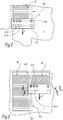
- the surface S to be coated is the hood of a car 8.
- the coating B visible at the figure 1 is formed by two layers B1 and B2 of coating product.
- the product layers B1 and B2 are bands extending in the longitudinal direction of the hood.
- the bands B1 and B2 are applied contiguously, that is to say so that there is no non-overlap zone between the bands B1 and B2.
- the figure 2 illustrates a step a) during which the applicator 6 makes a first pass to apply a first band B1 to the surface to be coated S.
- the direction of movement of the applicator 6 is shown in FIG. figure 2 by an arrow A1.
- the displacement direction A1 corresponds in fact to the director vector of the displacement line of the applicator 6. This vector is at each moment parallel to the surface to be coated.
- the line of displacement of the applicator is a straight line.
- the line of displacement of the applicator is a curve, with a radius of curvature substantially equal to that of the curved surface.
- the figure 3 illustrates a step b) during which the applicator 6 makes a second pass to apply a second band B2 contiguously to the first band B1.
- the direction of displacement of the applicator 6 during this second passage which is represented in FIG. figure 3 by an arrow A2 is substantially parallel to the direction of movement A1 of the applicator during the first pass.
- the line of displacement of the applicator 6 during the first pass is a first curve
- the line of displacement of the applicator during the second pass is a second curve parallel to the first curve.
- Any plane normal to a curve among the first and the second curve is then also a plane normal to the other, the distance between two respective points of the two curves which are contained in this normal plane being substantially constant.
- the applicator 6 is moved, during step b), as to partially cover the first band B1, that is to say as to cover the edge B1.1 of the first band B1 intended to be joined with the second band B2. This forces the recovery. This is particularly visible at figure 3 , where it can be seen that the applicator 6 projects slightly over the first band B1. If all the valves 66.1 to 66.i were open during the second passage of the applicator 6, the first band B1 would then be covered over a certain width.
- the covering width corresponds approximately to the width of the surface covered by a droplet from the first nozzle once it has spread. Alternatively, the covering width may be the surface covered after spreading by several nozzles, including four or five successive nozzles. In practice, the width of recovery depends on several parameters related to the imprecision of the robot, the phenomenon of "tubing", the problems of repeatability or the tolerances of the jets.
- the lap width is approximately 1 mm to 5 mm.
- the distance sensor 62.1 measures, at a time t, the distance that separates it from the surface to be coated S. As explained above, this measured distance corresponds to the application distance of the nozzle 60.1 at time t + ⁇ t. In sub-step b1), the distance sensor 62.1 thus measures the distance of application of the nozzle 30.1 at a point advanced with respect thereto in the path of the applicator 6.
- the electronic control unit 68 then collects the distance measured by the sensor 62.1 and compares, during a substep b2) this distance with the reference value D.
- An application area of a nozzle is defined as a portion of the surface to be coated to be coated with coating material by the nozzle.
- the zone of application of a nozzle is not the zone that the nozzle is capable of coating at time t, but the zone that the nozzle will be capable of coating at the same time. instant t + ⁇ t on the trajectory of the applicator 6.
- the distance measured by the distance sensor 62.1 at an advanced point relative to the first nozzle 60.1 in the path of the applicator is substantially less than the reference value D.
- the valve 66.1 of the first nozzle 60.1 is then closed during a sub-step b3) of the process of the invention and no coating product is applied by the first nozzle 60.1 when it reaches the advanced point, it that is, at time t + ⁇ t. This avoids an extra thickness at the junction between the two strips B1 and B2.
- the electronic control unit 68 considers that the value measured by a sensor is substantially lower than the reference value D when the difference between the two values, representing the actual thickness of the coating product. deposited on the surface S, is less than 50% of the theoretical wet thickness.
- the wet theoretical thickness corresponds to the thickness of the coating product on the surface S that it is desired to deposit before drying.
- the electronic control unit 68 may consider that the value measured by the sensor is substantially less than the reference value D when the difference between the two values is less than 20 ⁇ m.
- step b) the robot deviates from its set path, the distance measured in step b1) by the distance sensor 62.1 at an advanced point relative to the first nozzle 60.1 on the path the applicator 6 is substantially equal to the reference value D.
- the application area of the first nozzle 60.1 at an advanced point in the path of the applicator 6 is not coated with coating product.
- the valve 66.1 of the first nozzle 60.1 is open. The first nozzle then covers the surface S when it reaches the advanced point in the path of the applicator, that is to say at time t + ⁇ t. This makes it possible to avoid areas of non-overlap between the strips B1 and B2 and to obtain a perfect junction between the two layers of coating product B1 and B2.
- the zone Z1 for applying the nozzle 60.1 is covered by the band B1 applied during the first passage of the applicator 6.
- the laser beam F2 emitted by the sensor 62.1 is reflected by the coating strip B1 in a beam laser F'2, which is received by the receiver cell of the sensor 62.1.
- the time elapsed between the emission of the laser beam and the reception of the reflected laser beam is representative of the distance d2 between the sensor 62.1 and the coating layer B1.
- the sensor 62.1 communicates the distance d2 to the unit 68, which compares it with the reference value D.
- the distance d2 being smaller than the distance D, the electronic control unit 68 closes the valve 66.1 of the nozzle 60.1, as symbolized at the figure 4 by a cross.
- the laser beam F1 emitted by the other sensors 62.2 to 62.i is reflected in a laser beam F'1 directly by the surface S to be coated.
- the distance d1 measured by the sensors 62.2 to 62.i thus corresponds substantially to the reference value D mentioned above.
- the electronic control unit 68 therefore does not close the valves 66.2 to 66.i corresponding, as symbolized by the drops of product to the figure 4 .
- the second band B2 therefore has a width smaller than that of the first band B1.
- the distance sensors 62.1 to 62.i measure, at each instant t, the application distance of each of the nozzles 60.1 to 60.i at time t + ⁇ t.
- the electronic control unit 68 compares each of the values measured by the sensors 62.1 to 62.i with the reference value D.
- the electronic control unit 68 then closes all the valves for which the distance measured by the corresponding sensors is lower than the reference value D and opens the other valves, that is to say all the valves for which the distance measured by the corresponding sensors is substantially equal to the reference value D.
- the applicator 6 includes only one distance sensor 62, which is disposed on the side of the first nozzle 60.1.
- This distance sensor 62 differs from the distance sensors 62.1 to 62.i in that it is able to scan with its laser beam a line extending in a plane perpendicular to the direction of movement of the applicator 6.
- scanning angle ⁇ of the sensor 62 is such that the distance sensor 62 is able to determine the distance profile of the nozzles 60.1 to 60.i, that is to say to measure the distance of application of several successive nozzles. advanced points with respect thereto on the path of the applicator 6.
- the scanning angle ⁇ of the sensor 62 is such that the distance sensor 62 is able to measure the distance of application of each of the nozzles 60.1 to 60.i at points advanced with respect thereto on the path of the applicator 6.
- the scanning angle ⁇ of the sensor 62 may be between 10 ° and 120 °, preferably of the order of 90 °.
- the method of applying the coating product by means of the applicator 6 according to this second embodiment differs from the method described above in connection with the embodiment of the Figures 1 to 5 on the following points.
- the distance sensor 62 measures the distance of application of each of the nozzles 60.1 to 60.i at points advanced with respect thereto in the path A2 of the applicator 6.
- L electronic control unit 68 then collects these values from the sensor 62.
- the electronic control unit 68 Based on the distances measured by the distance sensor 62, the electronic control unit 68 establishes a surface profile over all or part of the application width of the applicator 6, and therefore a thickness profile of the coating. applied on the surface.
- the surface profile of the part corresponds to the intersection between the surface S to be coated in a plane perpendicular to the direction of movement of the applicator 6. What is known as a surface profile is therefore in reality a line.
- this thickness profile corresponds approximately to a step function with a step value corresponding to the thickness of the coating.
- layer of coating material B1 applied to the surface The electronic control unit is able, by analyzing the distance values measured by the sensor 62, to determine the position of the edge B1.1 of the first band B1 along the surface profile.
- the surface is flat, so that the surface profile can be likened to a line XX 'perpendicular to the direction of movement of the applicator 6 and perpendicular to a spray axis of the nozzles 60.1 to 60. i. We are talking about a thick front.
- the position of the edge B1.1 corresponds to the position of the point from which a net variation in distance measured by the sensor 62 is observed, this variation being due to the presence of the layer of coating material B1.
- the sensitivity of the distance sensor 62 is such that the electronic control unit is able to detect the thickness front regardless of the surface geometry to be coated, that is to say even for a left surface. Indeed, the accuracy of the sensor 62 is less than 10 microns, in particular of the order of 1 micron.
- the electronic control unit 68 closes all the valves which are arranged on a first side of the edge B1.1 and opens the valves which are arranged on the second side of the edge B1.1.
- the first side of the edge B1.1 corresponds to the side where the surface S is coated with product to the left of the edge B1.1 to the figure 7
- the second side of the edge B1.1 corresponds to the side where the surface S is devoid of coating product, to the right of the edge B1.1 to the figure 7 .
- the electronic control unit 68 closes the Nozzle valves 60.1 and 60.2 and opens the other valves.
- the coating product is therefore deposited at the locations of the surface S which are not covered by the band B1. It is thus possible to compensate for a defect of trajectory of the robot and to ensure a perfect junction between the two strips B1 and B2, without extra thickness.
- the applicator 6 comprises controllable flow valves 66.1 to 66.i, or proportional valves.
- the valves 66.1 to 66.i are piezoelectric valves whose excitation frequency can be adjusted according to the desired flow rate.
- valves 66.1 to 66.i are shutter type solenoid valves.
- the flow of the valves is then controlled by adjusting the opening frequency of the valves.
- the electronic control unit 68 establishes a thickness profile of the coating material layer in a plane perpendicular to the direction of movement of the applicator and controls the flow rate of the valves 66.1 to 66.i as a function of the thickness of the layer measured at each point of application of the nozzles. More precisely, the thickness of the layer is compared at each point with the theoretical thickness of the layer of coating product, this theoretical thickness being stored in the electronic control unit.
- the flow rate of the corresponding valve corresponds to 100% of the maximum flow rate.
- the thickness calculated by the unit 68 at a point is between 25% and 50% of the theoretical thickness, the flow rate of the corresponding valve corresponds to 75% of the maximum flow rate.
- the thickness calculated by the unit 68 at a point is between 50% and 75% of the theoretical thickness, the flow rate of the corresponding valve corresponds to 50% of the maximum flow rate.
- the corresponding valve is closed.
- the applicator 6 according to the third embodiment has the advantage that if the edge B1.1 of the band B1 is not a clean edge, for example because of the spreading of the coating product, the flow of the valves belonging to nozzles arranged to apply coating product on the edge B1.1 is controlled to overcome the lack of thickness at the junction.
- the applicator 6 Figures 9 to 11 differs from that of the first embodiment by the programming of the electronic control unit 68.
- This particular programming unit 68 aims to avoid wasting the coating product by applying the product of coating in the vacuum.
- This programming is advantageous in the case where the applicator 6 is used to paint a surface defining the edge of a room, such as a longitudinal edge of the roof of a car.
- the applicator 6 is oriented so that the first nozzle 60.1 is the nozzle of the row closest to the edge S.1 of the surface to be coated S.
- the applicator 6 is moved along the edge of the part to be coated, as represented by the arrow A3 at the figure 9 .
- the sensor 62.1 associated with the first nozzle 60.1 measures, at each instant t, the distance that separates it from the first object on which the beam F3 that it emits is reflected. For this, it evaluates the time between the emission of the laser beam F3 and the reception of the reflected laser beam F'3. This distance corresponds to the application distance of the first nozzle 60.1 at a time t + ⁇ t.
- this distance is substantially greater than the reference value D, it means that, at time t + ⁇ t, the part to be coated will not be in the field of application of the nozzle 60.1.
- the electronic control unit 68 then closes the valve 66.1 of the first nozzle 60.1 so as not to apply coating material through the nozzle 60.1 at time t + ⁇ t and thus avoid wasting coating product.
- the sensors 62.2 to 62.i and the valves 66.2 to 66.i are also optional for the embodiment of the invention.
- the distance sensors 62.1 to 62.i dynamically measure the application distance of each of the nozzles 60.1 to 60.i at an advanced point on the path of the applicator 6.
- the robot 2 therefore determines, in real time if the distance measured by each of the sensors 62.1 to 62.i is greater than the reference value D.
- the electronic control unit 68 then closes all the valves for which the distance measured by the corresponding sensors substantially exceeds the reference value D and open the other valves, that is to say all the valves for which the distance measured by the corresponding sensors is substantially equal to the reference value D.
- each of the valves 66.1 to 66.i as a function of the distances measured by their respective sensors makes it possible to apply a coating product on very left surfaces, such as the surface S Figures 9 and 10 , which delimits a curvilinear edge S.1, while moving the applicator 6 in a straight line without losing any coating product.
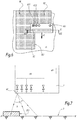
- the applicator 6 of the figure 12 differs from that of the first embodiment in that it comprises, in addition, a second row of distance sensors, respectively referenced 63.1 to 63.i, which are arranged perpendicular to the displacement A4 of the applicator 6.
- the sensors 63.1 to 63.i are thickness measuring sensors arranged late relative to the nozzles 60.1 to 60.i in the path of the applicator 6.
- the position of the nozzles 60.1 to 60.i at time t corresponds to the position of the sensors 63.1 to 63.i at time t + ⁇ t ', where ⁇ t' is a duration which depends on the speed of movement of the applicator 6 and the distance d6 'between the row of nozzles 60.1 at 60.i and the row of sensors 62.1 to 62.i, measured parallel to the direction of movement of the applicator 6.
- the duration ⁇ t' is equal to the duration ⁇ t. Otherwise, the duration ⁇ t and ⁇ t 'are different.
- the distance sensors 63.1 to 63.i are identical to the distance sensors 62.1 to 62.i and make it possible to measure the thickness of the film of coating product applied by the applicator 6.
- the distance applicator 63.1 to 63.i transmits the distance it measures to the electronic control unit 68, which compares the measured distances with the reference value D to determine the thickness of the coating product film applied to the surface S.
- the sensors 63.1 to 63.i thus make it possible to control the uniformity of the thickness of the film deposited by the applicator 6.
- the applicator 6 can make a new passage to standardize the thickness of the coating product applied to the surface S.
- the applicator 6 comprises only one thickness measurement sensor, comparable to the distance sensor 62.
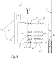
- the applicator of the figure 13 is designed to compensate for the effect of gravity g on product drops ejected through the nozzles 60.1 to 60.i.
- the effect of the gravity g is negligible on the direction of the drops of coating product ejected through the nozzles 60.1 to 60.i.
- the print head 6 is inclined at 90 °, as shown in FIG. figure 13 , the drops of coating material are deflected, under the effect of gravity g, relative to the spray axis of the nozzles, which is horizontal in the example. The deflection of the drops can lead to defects in coverage and / or areas of excess thickness.
- the applicator 6 is repositioned when the surface S to be coated is vertical or inclined.
- This repositioning step consists of moving the applicator 6 with a certain amplitude and in a direction A5 parallel to an axis of the nozzle row 60.1 to 60.i to compensate for the deviation of the coating product due to gravity g.
- the direction A5 of this compensatory displacement is oriented upwards. It is also perpendicular to the direction of movement of the applicator which, in the example of the figure 13 , is perpendicular to the plane of the figure 13 .
- the amplitude of displacement of the applicator 6 during the repositioning step is calculated dynamically as a function of the inclination of the applicator 6 with respect to the ground, the distance of application of the nozzles 60.1-60.i, the speed of ejection of the product through the nozzles and the size of the drops of coating product, it being understood that the size of the drops corresponds to the size of the nozzles 60.1 to 60.i. All these parameters are stored in memory in the controller of robot 2, which is not shown in the figures.
- the inclination value of the applicator 6 relative to the ground is updated automatically according to the orientation of the applicator 6 in the "tool" reference.
- the amplitude of the compensatory displacement, or "offset" in English can also be extracted from a prerecorded abacus, in which are recorded all the displacement values to be applied to compensate the effect of the gravity according to the various influential parameters.
- the repositioning step is performed by the multiaxis robot 2. More precisely, the amplitude of the compensating displacement is calculated by the robot controller, which sends a control signal to the actuator of the robot arm to move the applicator into the robot. the planned direction and with the expected amplitude.
- the electronic control unit 68 is programmed to close the valve of the nozzle or nozzles capable of projecting, because of gravity, the coating product on a zone Z1 of the surface S already coated.
- the applicator 6 moves at an altitude such that the nozzles 60.1 and 60.2 are capable of projecting drops of product on the zone Z1 already covered by the strip B1 of coating product.
- the valves 66.1 and 66.2 are closed.
- the valves to be closed are identified mainly according to the altitude of the applicator 6 relative to the strip B1 of coating product covering a portion of the surface S.
- the altitude of the applicator 6 is a setpoint parameter controlled by the controller of the robot.
- the applicator of the figure 14 is designed to obtain an irreproachable covering, even on a left surface S.
- the applicator 6 of the figure 14 includes proportional valves.
- each nozzle 60.k among the nozzles 60.1 to 60.i is intended to coat a certain portion Sk of the surface S, where k is a natural integer between 1 and i.
- the nozzle 60.2 is intended to coat the portion S2 of the surface S during the displacement of the applicator 6, while the nozzle 60.6 is intended to coat the portion S6 of the surface S.
- these surface portions appear as segments in bold lines.
- the respective portions of the nozzles 60.1 to 60.i are joined.
- the width of the surface portions Sk depends on the width of the nozzles and the coefficient of spreading. When the surface portion Sk is substantially perpendicular to the spray axis of the nozzles, the area of the surface portion Sk substantially corresponds to the area of the coated surface, at a nominal flow rate, once the drop from the 60.k nozzle spread.
- the surface portion Sk is not perpendicular to the spray axis of the nozzles, as is the case, for example, for the surface portion S2 relative to the nozzle 60.2, the area of the coated surface at a nominal flow rate is less than the area of the surface portion Sk to be coated. There is therefore a defect of recovery.
- each nozzle 60.k among the nozzles 60.1 to 60.i is controlled according to the inclination of the respective surface portion Sk with respect to a plane perpendicular to the direction of spray of nozzles 60.1 to 60.i. In the configuration of the figure 14 this plane is horizontal.
- the flow rate applied is all the more important that the portion of the surface to be coated is inclined, so as to compensate for the lack of coating product.
- each surface portion Sk with respect to the plane perpendicular to the spray axis of the nozzles is calculated by the electronic control unit 68 by determining the distance difference ⁇ D k , measured parallel to the spray axis.
- the end points of the surface portion S2 are represented with the references S2.1 and S2.2, the difference between these two points being represented by the measurement ⁇ D 2 corresponding to the difference between the distance D1 and the distance D2.
- the electronic unit 68 therefore compares a distance D1, measured parallel to the spray axis of the nozzles, between the point S2.1 and the distance sensor and a distance D2, measured in parallel. to the spray nozzle axis, between point S2.2 and the distance sensor.
- the flow of coating product flowing through a nozzle 60.k is even higher than the distance difference ⁇ D k is high.
- the relationship between the rate and the distance difference ⁇ D k is a linear type relationship.
- the surface portion S6 intended to be covered by the nozzle 60.6 has a smaller area than the surface portion S2 intended to be covered by the nozzle 60.2.
- the coating product flow applied by the nozzle 60.2 is higher than the coating product flow applied by the nozzle 60.6.
- the applicator 6 comprises several rows of nozzles aligned with each other.
- the applicator 6 further comprises a second row of nozzles disposed downstream of the sensor or sensors 63.1 to 63.i in the path of the applicator 6.
- the second row of nozzles is arranged late relative to each thickness measuring sensor 63.1-63.i on the path A4 of the applicator 6.
- This second row of nozzles also comprises i nozzles, which are distributed identically to the row of nozzles 60.1 to 60.i.
- This second row of nozzles makes it possible to compensate for any lack of overlap, or lack of thickness, detected by the sensor or sensors 63.1 to 63.i and thus to homogenize the thickness of the layer of coating product applied without making any difference. 'back and forth.
- Such a lack of thickness can appear when a nozzle of the first row, that is to say the upstream row of nozzles 60.1 to 60.i, is clogged, or at least has a malfunction.
- a lack of thickness can also appear during the coating of a left surface, as represented in FIG. figure 14 in connection with the seventh embodiment, or during defective covering at the junction between two strips of coating material.
- Another advantage of this variant is that the control of the valves 66.1 to 66.i of the first row of nozzles can be simplified because the covering defects can be corrected almost instantaneously.
- the applicator 6 comprises a single valve 66.1 corresponding to the valve of the first nozzle 60.1 of the row.
- the applicator 6 includes only one sensor 62.1 designed to measure the distance of application of the first nozzle 60.1 at a point advanced with respect thereto in the path of the applicator 6.
- only the first nozzle 60.1 and the last nozzle 60.i of the row comprise a valve, respectively 66.1 and 66.i.
- the applicator comprises only two distance sensors, respectively 62.1 and 62.i, designed to respectively measure the application distance of the first nozzle 60.1 and the last nozzle 60.i at an advanced point on the path of the applicator 6.
- ultrasonic sensors other types of distance sensors may be envisaged, such as ultrasonic sensors.
Description
L'invention concerne un applicateur de produit de revêtement, un robot multiaxes muni de cet applicateur et un procédé d'application d'un produit de revêtement sur la surface d'une pièce, telle que le capot d'un véhicule automobile. En particulier, le procédé selon l'invention permet d'appliquer deux couches de produit de revêtement avec une jonction parfaite entre les deux couches.The invention relates to a coating product applicator, a multi-axis robot provided with this applicator and a method of applying a coating product to the surface of a workpiece, such as the hood of a motor vehicle. In particular, the method according to the invention makes it possible to apply two layers of coating product with a perfect junction between the two layers.
Le document
La tendance actuelle dans l'automobile, pour les véhicules de sport notamment, est celle des voitures personnalisables. Ainsi, les constructeurs automobiles proposent à leurs clients des voitures dont la peinture de la carrosserie peut être personnalisée. La carrosserie peut ainsi être multicolore, avec différents motifs, tels que des bandes. On observe souvent, sur les voitures de sport notamment, une ou plusieurs bandes de couleurs différentes qui s'étendent dans le sens longitudinal sur le capot de la voiture. Pour réaliser ce type de bandes, une technique connue consiste à appliquer un masque sur le reste de la carrosserie pour n'exposer que la surface du capot correspondant à une bande en cours d'application. En pratique, ce masque est réalisé avec du papier adhésif qui est retiré une fois le motif créé. Toutefois, cette technique est relativement pénible car elle nécessite d'appliquer manuellement un masque sur la carrosserie de chaque véhicule.The current trend in the automobile, especially for sports vehicles, is that of customizable cars. Thus, car manufacturers offer their customers cars whose body paint can be customized. The body can be multicolored, with different patterns, such as bands. One often observes, on sports cars in particular, one or more bands of different colors which extend in the longitudinal direction on the hood of the car. To achieve this type of strips, a known technique is to apply a mask on the rest of the body to expose only the surface of the cover corresponding to a band being applied. In practice, this mask is made with adhesive paper that is removed once the pattern created. However, this technique is relatively difficult because it requires manually applying a mask on the body of each vehicle.
Une autre technique, décrite notamment dans
Il est connu que les robots multiaxes ont des difficultés à suivre une trajectoire prédéterminée, par exemple en ligne droite. Ainsi, la trajectoire réelle décrite par le robot est inscrite dans un tube imaginaire, qui est centré sur la trajectoire théorique et dont le diamètre extérieur dépend de la précision du robot. On parle d'un phénomène de « tubing », lequel peut entrainer un défaut de recouvrement entre deux bandes de peinture au niveau de la jonction entre les deux bandes. Pour pallier ce problème, il est indiqué au paragraphe [0144] de
Un inconvénient de cette technologie est que la jonction n'est pas parfaite lorsque le revêtement est appliqué sur des surfaces bombées, comme le capot d'une voiture. On observe alors des zones de non recouvrement entre deux passages de l'applicateur.A disadvantage of this technology is that the junction is not perfect when the coating is applied to curved surfaces, such as the hood of a car. Non-overlapping zones are then observed between two passages of the applicator.
C'est à ces inconvénients qu'entend plus particulièrement remédier l'invention en proposant un applicateur de produit de revêtement permettant d'obtenir une jonction parfaite entre deux bandes issues de deux passages successifs, même sur une surface bombée, comme le capot d'une voiture.It is these drawbacks that the invention more particularly intends to remedy by proposing a coating product applicator making it possible to obtain a perfect connection between two strips coming from two successive passages, even on a curved surface, such as the hood of a car.
A cet effet l'invention concerne un applicateur d'un produit de revêtement sur une surface à revêtir, comprenant au moins une rangée de buses, parmi lesquelles au moins la première buse de la rangée comporte une vanne. Conformément à l'invention, l'applicateur comprend, en outre, au moins un capteur de distance, pour mesurer une distance d'application de la première buse à un point avancé par rapport à celle-ci sur un trajet de l'applicateur, et une unité électronique de commande de la vanne, qui est programmée pour collecter la distance mesurée par le capteur de distance, et, en fonction de la valeur de la distance collectée, pour ouvrir ou fermer la vanne. Chaque buse de la rangée comprend une vanne, alors que le capteur de distance est apte à mesurer la distance d'application de certaines buses au moins de la rangée à des points respectivement avancés par rapport à celles-ci sur le trajet de l'applicateur. Le capteur de distance est un capteur laser, comprenant une cellule émettrice d'un faisceau laser et une cellule réceptrice d'un faisceau laser réfléchi, alors que le capteur de distance est apte à balayer avec son faisceau une ligne perpendiculaire à la direction de déplacement de l'applicateur, de manière à mesurer la distance d'application de certaines buses au moins de la rangée, à des points avancés par rapport à celles-ci sur le trajet de l'applicateur.To this end the invention relates to an applicator of a coating product on a surface to be coated, comprising at least one row of nozzles, among which at least the first nozzle of the row comprises a valve. According to the invention, the applicator further comprises at least one distance sensor, for measuring an application distance of the first nozzle at an advanced point with respect thereto over a path of the applicator, and an electronic control unit of the valve, which is programmed to collect the distance measured by the distance sensor, and, depending on the value of the collected distance, to open or close the valve. Each nozzle of the row comprises a valve, while the distance sensor is able to measure the distance of application of at least some nozzles of the row to points respectively advanced relative to them in the path of the applicator . The distance sensor is a laser sensor, comprising a cell emitting a laser beam and a receiver cell of a reflected laser beam, while the distance sensor is able to scan with its beam a line perpendicular to the direction of travel. the applicator, so as to measure the application distance of at least some nozzles of the row at points advanced relative thereto in the path of the applicator.
Selon des aspects avantageux mais non obligatoires de l'invention, l'applicateur de produit de revêtement comprend l'une quelconque des caractéristiques suivantes, prises dans toute combinaison techniquement admissible :
- L'unité électronique de commande est programmée pour collecter les distances mesurées par le capteur de distance, afin de déterminer un profil de la surface à revêtir sur tout ou partie de la largeur d'application de l'applicateur, analyser le profil de surface pour détecter la position d'un bord d'une couche de produit de revêtement le long du profil de la surface, ouvrir toutes les vannes des buses qui sont disposées d'un côté du bord et fermer les vannes disposées de l'autre côté du bord le long du profil de la surface.
- Les vannes sont des vannes proportionnelles, alors que l'unité électronique de commande est programmée pour établir un profil d'épaisseur de la couche de produit de revêtement dans un plan perpendiculaire à la direction de déplacement de l'applicateur et pour contrôler le débit des vannes en fonction de l'épaisseur de la couche mesurée en chacun des points d'application des buses.
- Chaque buse de la rangée comprend une vanne et des capteurs de distance respectifs sont prévus pour mesurer une distance d'application de chaque buse à un point respectivement avancé par rapport à celles-ci sur le trajet de l'applicateur.
- Chaque vanne est une vanne piézoélectrique, dont le débit dépend d'une fréquence d'excitation de la vanne.
- L'unité électronique de commande est programmée pour fermer la vanne de la première buse lorsque la distance mesurée par le capteur est sensiblement supérieure à une valeur de référence.
- L'applicateur comprend en outre au moins un capteur de mesure d'épaisseur, configuré pour mesurer respectivement l'épaisseur du film de produit de revêtement appliqué par les buses en des points reculés par rapport à celles-ci sur le trajet de l'applicateur.
- L'applicateur comprend une autre rangée de buses, disposée en retard par rapport à chaque capteur de mesure d'épaisseur sur le trajet de l'applicateur.
- The electronic control unit is programmed to collect the distances measured by the distance sensor, in order to determine a profile of the surface to be coated over all or part of the application width of the applicator, to analyze the surface profile for detect the position of an edge of a layer of coating material along the surface profile, open all nozzle valves that are arranged on one side of the edge and close the valves on the other side of the edge along the profile of the surface.
- The valves are proportional valves, while the electronic control unit is programmed to establish a thickness profile of the coating material layer in a plane perpendicular to the direction of movement of the applicator and to control the flow rate of the coating material. valves as a function of the thickness of the layer measured at each of the nozzle application points.
- Each nozzle in the row comprises a valve and respective distance sensors are provided for measuring an application distance of each nozzle at a point respectively advanced relative thereto in the path of the applicator.
- Each valve is a piezoelectric valve, the flow rate of which depends on a frequency of excitation of the valve.
- The electronic control unit is programmed to close the valve of the first nozzle when the distance measured by the sensor is substantially greater than a reference value.
- The applicator further comprises at least one thickness measuring sensor, configured to respectively measure the thickness of the coating material film applied by the nozzles at points remote from them in the applicator path. .
- The applicator comprises another row of nozzles arranged late relative to each thickness measuring sensor in the path of the applicator.
L'invention concerne également un robot multiaxes, comprenant un bras mobile sur lequel est monté un applicateur tel que défini précédemment.The invention also relates to a multi-axis robot, comprising a mobile arm on which is mounted an applicator as defined above.
L'invention concerne aussi un procédé d'application d'un produit de revêtement sur la surface d'une pièce, ce procédé étant mis en oeuvre au moyen d'un applicateur comprenant au moins une rangée de buses, parmi lesquelles au moins la première buse de la rangée comporte une vanne, ce procédé comprenant des étapes consistant à :
- a) déplacer l'applicateur selon une première direction pour appliquer une première couche de produit de revêtement, et à
- b) déplacer l'applicateur selon une deuxième direction sensiblement parallèle à la première direction pour appliquer une seconde couche de produit de revêtement de manière jointive à la première couche.
- a) moving the applicator in a first direction to apply a first coat of coating product, and
- b) moving the applicator in a second direction substantially parallel to the first direction to apply a second layer of coating material contiguously to the first layer.
Conformément à l'invention, l'étape b) comprend des sous-étapes consistant à mesurer au moins une distance d'application de la première buse à un point avancé par rapport à celle-ci sur un trajet de l'applicateur, et en fonction de la distance d'application mesurée, à ouvrir ou fermer la vanne.In accordance with the invention, step b) comprises substeps of measuring at least an application distance of the first nozzle at an advanced point with respect thereto on a path of the applicator, and depending on the measured application distance, to open or close the valve.
Selon des aspects avantageux, mais non obligatoires, le procédé comprend une ou plusieurs des caractéristiques suivantes, prises dans toute combinaison techniquement admissible :
- La sous-étape b1) consiste à collecter des distances d'application de certaines buses au moins de la rangée à des points respectivement avancés par rapport à celles-ci sur le trajet de l'applicateur, afin de déterminer un profil de la surface à revêtir sur tout ou partie de la largeur d'application de l'applicateur, alors que la sous-étape b2) consiste à analyser le profil de surface pour détecter la position d'un bord de la première couche de produit de revêtement le long du profil de la surface et à ouvrir toutes les vannes des buses qui sont disposées d'un côté du bord et fermer les vannes disposées de l'autre côté du bord le long du profil de la surface.
- Les vannes sont des vannes proportionnelles et l'étape b) comprend d'autres sous-étapes consistant à établir un profil d'épaisseur de la couche de produit de revêtement le long de l'axe, et à contrôler le débit des vannes en fonction de l'épaisseur de la couche en chacun des points avancés.
- Le procédé comprend en outre une étape consistant à repositionner l'applicateur lorsque la surface est verticale ou inclinée. Cette étape de repositionnement consiste à déplacer l'applicateur avec une certaine amplitude et selon une direction parallèle à un axe de la rangée de buses pour compenser la déviation du produit de revêtement due à la gravité.
- L'amplitude de déplacement de l'applicateur lors de l'étape de repositionnement est calculée dynamiquement en fonction de l'inclinaison de l'applicateur par rapport au sol, de la distance d'application des buses, de la vitesse d'éjection du produit à travers les buses et de la taille des buses ou est extraite d'un abaque préenregistré.
- Le procédé comprend en outre une étape consistant à fermer la vanne de la ou des buses susceptibles de projeter, à cause de la gravité, du produit de revêtement sur une zone de la surface recouverte par la première couche de produit de revêtement.
- Les vannes sont des vannes proportionnelles et l'étape b) comprend en outre les sous-étapes suivantes: i) évaluer l'inclinaison de la portion de surface (Sk) destinée à être recouverte par chaque buse par rapport à un plan perpendiculaire à un axe de pulvérisation des buses, et ii) contrôler le débit de produit de revêtement appliqué par chaque buse en fonction de l'inclinaison de la portion de surface (Sk) destinée à être recouverte par la buse correspondante.
- Sub-step b1) is to collect application distances of at least some nozzles from the row at points respectively advanced with respect thereto along the path of the applicator, to determine a profile of the surface to be coating all or part of the application width of the applicator, while the sub-step b2) is to analyze the surface profile to detect the position of an edge of the first layer of coating product along the profile of the surface and to open all the valves of the nozzles that are arranged on one side of the edge and close the valves arranged on the other side of the edge along the profile of the surface.
- The valves are proportional valves and step b) comprises other substeps of establishing a thickness profile of the coating product layer along the axis, and controlling the flow of valves based on the thickness of the layer in each of the advanced points.
- The method further comprises a step of repositioning the applicator when the surface is vertical or inclined. This repositioning step consists of moving the applicator with a certain amplitude and in a direction parallel to an axis of the row of nozzles to compensate for the deviation of the coating product due to gravity.
- The amplitude of displacement of the applicator during the repositioning step is calculated dynamically as a function of the inclination of the applicator relative to the ground, the nozzle application distance, the ejection speed of the applicator produced through the nozzles and nozzle size or is extracted from a prerecorded abacus.
- The method further comprises a step of closing the valve of the nozzle or nozzles capable of projecting, due to gravity, the product of coating on an area of the surface covered by the first layer of coating material.
- The valves are proportional valves and step b) further comprises the following substeps: i) evaluating the inclination of the surface portion (Sk) to be covered by each nozzle with respect to a plane perpendicular to a spraying axis of the nozzles, and ii) controlling the rate of coating product applied by each nozzle according to the inclination of the surface portion (Sk) to be covered by the corresponding nozzle.
Si, lors de l'étape b), le robot suit sa trajectoire de consigne, la distance mesurée par le capteur de distance à un point avancé par rapport à la première buse sur le trajet de l'applicateur est sensiblement inférieure à une valeur de référence, laquelle correspond à la distance d'application des buses lorsqu'il n'y a pas de produit de revêtement. Cela signifie que la zone d'application de la première buse à un point avancé sur le trajet de l'applicateur est déjà recouverte de produit de revêtement. Grâce à l'invention, la vanne de la première buse est fermée et aucun produit de revêtement n'est appliqué par la première buse lorsque celle-ci parvient au point avancé, ce qui permet d'éviter une surépaisseur au niveau de la jonction entre les deux bandesIf, during step b), the robot follows its set path, the distance measured by the distance sensor at an advanced point relative to the first nozzle in the path of the applicator is substantially less than a value of reference, which corresponds to the distance of application of the nozzles when there is no coating product. This means that the area of application of the first nozzle at an advanced point in the path of the applicator is already coated with coating material. Thanks to the invention, the valve of the first nozzle is closed and no coating product is applied by the first nozzle when it reaches the advanced point, which avoids an extra thickness at the junction between both bands
En revanche, si le robot dévie d'une trajectoire de consigne, par exemple à cause du phénomène de « tubing », la distance mesurée par le capteur à un point avancé par rapport à la première buse sur le trajet de l'applicateur est sensiblement égale à la valeur de référence. Cela signifie que la zone d'application de la première buse à un point avancé sur le trajet de l'applicateur n'est pas recouverte de produit de revêtement. Grâce à l'invention, la vanne de la première buse est ouverte. La première buse revêt alors la surface lorsqu'elle parvient au point avancé sur le trajet de l'applicateur. Cela permet d'éviter les zones de non recouvrement et d'obtenir une jonction parfaite entre les deux couches de produit de revêtement. La vanne de la première buse est donc contrôlée de manière dynamique, c'est-à-dire en temps réel, sur le trajet de l'applicateur. Ce réglage dynamique permet d'appliquer une bande de produit de revêtement avec une jonction parfaite par rapport à une autre bande existante, même sur une surface bombée telle que la surface d'un capot de voiture. La jonction entre deux bandes de peinture est donc assurée par le pilotage dynamique de la vanne, sans utiliser un robot ultra-précis ni un contrôleur de trajectoire perfectionné.On the other hand, if the robot deviates from a target trajectory, for example because of the phenomenon of "tubing", the distance measured by the sensor at an advanced point relative to the first nozzle in the path of the applicator is substantially equal to the reference value. This means that the area of application of the first nozzle at an advanced point in the path of the applicator is not covered with coating material. Thanks to the invention, the valve of the first nozzle is open. The first nozzle then covers the surface when it reaches the advanced point in the path of the applicator. This makes it possible to avoid areas of non-overlap and to obtain a perfect junction between the two layers of coating product. The valve of the first nozzle is therefore controlled dynamically, that is to say in real time, in the path of the applicator. This dynamic adjustment makes it possible to apply a strip of coating product with a perfect junction with respect to another existing strip, even on a curved surface such as the surface of a car hood. The junction between two strips of paint is therefore ensured by the dynamic control of the valve, without using an ultra-precise robot or an advanced trajectory controller.
L'invention et d'autres avantages de celle-ci apparaîtront plus clairement à la lumière de la description qui va suivre de sept modes de réalisation d'un applicateur de produit de revêtement conforme à son principe, donnée uniquement à titre d'exemple et faite en référence aux dessins annexés dans lesquels :
- la
figure 1 est une représentation schématique d'un robot multiaxes comprenant un bras mobile sur lequel est monté un applicateur de produit de revêtement conforme à l'invention, - la
figure 2 est une vue partielle en élévation dans le sens de la flèche II à lafigure 1 , représentant l'applicateur de produit de revêtement dans une configuration où il effectue un premier passage sur une surface à revêtir, de manière à former une première bande, - la
figure 3 est une vue analogue à lafigure 2 , représentant l'applicateur de produit de revêtement dans une configuration où il effectue un second passage sur la surface à revêtir, de manière à appliquer une seconde bande jointive à la première bande, - la
figure 4 est une vue en coupe schématique de l'applicateur selon la ligne IV-IV de lafigure 3 , - la
figure 5 est une coupe schématique de l'applicateur selon la ligne V-V de lafigure 3 , - la
figure 6 est une vue analogue à lafigure 3 , dans laquelle l'applicateur est conforme à un deuxième mode de réalisation de l'invention, - la
figure 7 est une coupe schématique selon la ligne VII-VII de lafigure 6 , - la
figure 8 est un schéma relatif à un troisième mode de réalisation d'un applicateur selon l'invention, - les
figures 9 et 10 sont des vues analogues à lafigure 3 et représentent un applicateur de produit de revêtement conforme à un quatrième mode de réalisation, dans une configuration où il effectue un passage le long d'un bord d'une surface à revêtir, - la
figure 11 est une coupe schématique de l'applicateur de produit de revêtement dans le plan XI-XI de lafigure 10 , - la
figure 12 est une vue analogue à lafigure 3 représentant un applicateur de produit de revêtement conforme à un cinquième mode de réalisation de l'invention, - la
figure 13 est une vue analogue à lafigure 4 pour un applicateur de produit de revêtement conforme à un sixième mode de réalisation de l'invention, cet applicateur étant conçu pour compenser en outre l'effet de la gravité, et - la
figure 14 est une vue analogue à lafigure 4 pour un applicateur de produit de revêtement conforme à un septième mode de réalisation de l'invention, cet applicateur étant conçu pour obtenir un recouvrement irréprochable, même sur une surface gauche.
- the
figure 1 is a schematic representation of a multi-axis robot comprising a movable arm on which is mounted a coating product applicator according to the invention, - the
figure 2 is a partial elevation view in the direction of arrow II to thefigure 1 , representing the coating product applicator in a configuration where it makes a first pass on a surface to be coated, so as to form a first strip, - the
figure 3 is a view similar to thefigure 2 , representing the coating product applicator in a configuration where it makes a second pass on the surface to be coated, so as to apply a second band joined to the first strip, - the
figure 4 is a schematic sectional view of the applicator along line IV-IV of thefigure 3 , - the
figure 5 is a schematic section of the applicator according to the VV line of thefigure 3 , - the
figure 6 is a view similar to thefigure 3 in which the applicator conforms to a second embodiment of the invention, - the
figure 7 is a schematic section along line VII-VII of thefigure 6 , - the
figure 8 is a diagram relating to a third embodiment of an applicator according to the invention, - the
Figures 9 and 10 are similar views to thefigure 3 and show a coating product applicator according to a fourth embodiment, in a configuration where it passes along an edge of a surface to be coated, - the
figure 11 is a schematic section of the coating product applicator in the XI-XI plane of thefigure 10 , - the
figure 12 is a view similar to thefigure 3 representing a coating product applicator according to a fifth embodiment of the invention, - the
figure 13 is a view similar to thefigure 4 for a coating product applicator according to a sixth embodiment of the invention, this applicator being designed to further compensate for the effect of gravity, and - the
figure 14 is a view similar to thefigure 4 for a coating product applicator according to a seventh embodiment of the invention, this applicator being designed to obtain an irreproachable covering, even on a left surface.
Sur la
L'applicateur de produit de revêtement 6 comprend une rangée de buses, référencées 60.1 à 60.i sur les figures, i étant le nombre de buses de la rangée, qui est supérieur ou égal à 2 et par exemple compris entre 10 et 100. Les buses 60.1 à 60.i de la rangée sont disposées de manière perpendiculaire à la direction de déplacement de l'applicateur 6 lors de l'application du produit de revêtement. Dans l'exemple, les buses 60.1 à 60.i sont configurées pour déposer le produit de revêtement goutte par goutte. Une fois déposée, la goutte s'étale sur la surface à revêtir. On définit un coefficient d'étalement comme le rapport entre l'aire de la surface revêtue une fois la goutte étalée et le diamètre de la goutte. Ce coefficient d'étalement dépend notamment du type de produit de revêtement utilisé. Il est compris entre 5 et 10, souvent de l'ordre de 7.The
De manière alternative, les buses peuvent être conformées pour former un filet continu de produit de revêtement.Alternatively, the nozzles may be shaped to form a continuous net of coating material.
Avantageusement, les buses 60.1 à 60.i sont des trous pratiqués dans une plaque, la largeur des gouttes ou du filet correspondant alors à la largeur des trous.Advantageously, the nozzles 60.1 to 60.i are holes in a plate, the width of the drops or the net then corresponding to the width of the holes.
Comme visible à la
Dans l'exemple, les vannes 66.1 à 66.i sont des vannes à commande électrique, notamment des vannes piézoélectriques.In the example, the valves 66.1 to 66.i are electrically operated valves, in particular piezoelectric valves.
Les vannes piézoélectriques sont des vannes dites excitatrices, comprenant un élément piézoélectrique déformable sous l'application d'une excitation électrique. Ce type de vanne fonctionne de la manière suivante. Lorsque l'élément piézoélectrique n'est pas excité, le fluide reste à l'intérieur du réservoir 64 du fait que la pression atmosphérique est supérieure à la pression du réservoir. En revanche, lorsque l'élément piézoélectrique est excité, par exemple avec une tension alternative, celui-ci génère alors localement une surpression permettant au fluide de s'écouler hors du réservoir.Piezoelectric valves are so-called exciter valves, comprising a deformable piezoelectric element under the application of electrical excitation. This type of valve works as follows. When the piezoelectric element is not excited, the fluid remains inside the
Le débit de produit de revêtement éjecté à travers les buses 60.1 à 60.i peut être réglé en agissant sur la fréquence d'excitation des vannes respectives 66.1 à 66.i. On parle alors de vannes proportionnelles.The flow of coating material ejected through the nozzles 60.1 to 60.i can be adjusted by acting on the excitation frequency of the respective valves 66.1 to 66.i. We then speak of proportional valves.
Dans le présent document, on appelle vanne tout dispositif permettant de contrôler l'écoulement du produit de revêtement. En particulier, selon une variante non représentée, les vannes 66.1 à 66.i sont des vannes dites à obturateur, qui fonctionnent par obturation sélective du conduit de passage du fluide.In this document, a valve is defined as any device for controlling the flow of the coating product. In particular, according to a variant not shown, the valves 66.1 to 66.i are so-called shutter valves, which operate by selective sealing of the fluid passage conduit.
Selon une autre variante non représentée, un autre type de vanne excitatrice peut être envisagé pour équiper l'applicateur 6. Il peut s'agir d'une vanne avec une excitation de type thermique, acoustique, pneumatique ou encore électrostatique.According to another variant not shown, another type of exciter valve may be envisaged to equip the
L'applicateur 6 comprend des capteurs de distance 62.1 à 62.i qui sont positionnés à des points avancés par rapport aux buses 60.1 à 60.i sur le trajet de l'applicateur 6. Les capteurs 62.1 à 62.i sont agencés sous forme de rangée, laquelle est parallèle à la rangée de buses 60.1 à 60.i. L'applicateur 6 comporte autant de capteurs de distance 62.1 à 62.i que de buses 60.1 à 60.i. Chaque capteur 62.1 à 62.i est donc associé à une buse. Par exemple, le capteur 62.1 est associé à la buse 60.1. Ainsi, la position des capteurs 62.1 à 62.i le long du trajet de l'applicateur 6 à un instant t correspond à celle des buses 60.1 à 60.i à l'instant t+Δt, où Δt est une durée qui dépend de la vitesse de déplacement de l'applicateur 6 et de la distance d6 entre la rangée de buse 60.1 à 60.i et la rangée de capteurs 32.1 à 62.i, mesurée parallèlement à la direction de déplacement de l'applicateur 6. Les capteurs de distance 62.2 à 62.i sont optionnels pour la réalisation de l'invention.The
Les capteurs de distances 62.1 à 62.i mesurent, à chaque instant t, la distance entre l'applicateur 6 et la portion de la surface à revêtir S qui se trouve en regard d'eux. Or, à l'instant t+Δt, les buses 62.1 à 62.i atteignent la position des capteurs 60.1 à 60.i à l'instant t. La distance mesurée par les capteurs 62.1 à 62.i à l'instant t correspond donc respectivement à la distance d'application des buses 60.1 à 60.i à l'instant t+Δt, c'est-à-dire à la distance entre les buses et la pièce à revêtir, mesurée selon une direction parallèle à un axe de projection du produit de revêtement à travers les buses. Chaque capteur de distance 62.1 à 62.i mesure donc la distance d'application de la buse à laquelle il est associé à un point, sur le trajet de l'applicateur 6, qui est avancé par rapport à la buse 60.1 à 60.i qui lui est associée.The distance sensors 62.1 to 62.i measure, at each instant t, the distance between the
Avantageusement, chaque capteur de distance 62.1 à 62.i est un capteur laser, comprenant une cellule émettrice d'un faisceau laser et une cellule réceptrice d'un faisceau laser réfléchi, sur la surface S. Le faisceau laser émis par la cellule émettrice est sensiblement parallèle à l'axe de projection du produit de revêtement à travers les buses 60.1 à 60.i. Dans l'exemple, la précision de chaque capteur est inférieure à 10 µm, notamment de l'ordre de 1 µm.Advantageously, each distance sensor 62.1 to 62.i is a laser sensor, comprising a cell emitting a laser beam and a receiver cell of a reflected laser beam, on the surface S. The laser beam emitted by the emitting cell is substantially parallel to the axis of projection of the coating product through the nozzles 60.1 to 60.i. In the example, the accuracy of each sensor is less than 10 microns, in particular of the order of 1 micron.
L'applicateur 6 comprend en outre une unité électronique de commande 68. L'unité électronique de commande 68 contrôle l'ouverture et la fermeture de chacune des vannes 66.1 à 66.i. Pour ce faire, l'unité 68 envoie à chacune des vannes 66.1 à 66.i des signaux de commande, parmi lesquels le signal électrique S1 de commande de la vanne 66.1 est représenté schématiquement à la
Dans l'exemple, cette valeur de référence D est une valeur prédéterminée qui est identique pour toutes les buses 60.1 à 60.i. En outre, c'est une valeur constante dans le temps, c'est-à-dire que la même distance d1 est utilisée quelle que soit la position de l'applicateur 6 sur son trajet. La distance d1 peut alors être préenregistrée en mémoire dans l'unité électronique de commande 68.In the example, this reference value D is a predetermined value which is identical for all the nozzles 60.1 to 60.i. In addition, it is a constant value in time, that is to say that the same distance d1 is used regardless of the position of the
Cependant, à titre de variante, la valeur de référence D est propre à chaque buse et/ou n'est pas une fonction constante dans le temps, c'est-à-dire que cette valeur de référence D varie selon la position de l'applicateur 6 sur son trajet. Cette variante est avantageuse lorsque la surface à revêtir est gauche, c'est-à-dire lorsque la distance d'application varie sensiblement d'une buse à l'autre et/ou varie sensiblement sur le trajet de l'applicateur 6. Dans ce cas, la distance D à laquelle est comparée la distance transmise par les capteurs à chaque instant peut être acquise par apprentissage, en déplaçant l'applicateur 6 une première fois « à blanc », c'est-à-dire sans appliquer de produit de revêtement. Les valeurs acquises par les capteurs 62.1 à 62.i lors de l'apprentissage servent alors de distances de référence, au même titre que la valeur de référence D.However, as a variant, the reference value D is specific to each nozzle and / or is not a function that is constant in time, that is to say that this reference value D varies according to the position of the nozzle.
Un procédé d'application d'un revêtement B sur une surface à revêtir S est décrit ci-dessous en relation avec les
La
La
Lors du deuxième passage, l'applicateur 6 est déplacé, lors de l'étape b), comme pour recouvrir partiellement la première bande B1, c'est-à-dire comme pour recouvrir le bord B1.1 de la première bande B1 destiné à être jointif avec la seconde bande B2. On force ainsi le recouvrement. Ceci est particulièrement visible à la
Comme visible à la
L'unité électronique de commande 68 collecte alors la distance mesurée par le capteur 62.1 et compare, lors d'une sous-étape b2) cette distance avec la valeur de référence D.The
On définit une zone d'application d'une buse comme une portion de la surface à revêtir destinée à être recouverte de produit de revêtement par la buse. Autrement dit, au sens de la présente demande, la zone d'application d'une buse n'est pas la zone que la buse est capable de revêtir à l'instant t, mais la zone que la buse sera capable de revêtir à l'instant t+Δt sur la trajectoire de l'applicateur 6.An application area of a nozzle is defined as a portion of the surface to be coated to be coated with coating material by the nozzle. In other words, for the purposes of the present application, the zone of application of a nozzle is not the zone that the nozzle is capable of coating at time t, but the zone that the nozzle will be capable of coating at the same time. instant t + Δt on the trajectory of the
Si le robot suit sa trajectoire de consigne, la distance mesurée par le capteur de distance 62.1 à un point avancé par rapport à la première buse 60.1 sur le trajet de l'applicateur est sensiblement inférieure à la valeur de référence D. Cela signifie que la zone d'application de la première buse à un point avancé sur le trajet de l'applicateur est déjà recouverte de produit de revêtement. La vanne 66.1 de la première buse 60.1 est alors fermée lors d'une sous étape b3) du procédé de l'invention et aucun produit de revêtement n'est appliqué par la première buse 60.1 lorsque celle-ci parvient au point avancé, c'est-à-dire à l'instant t+Δt. On évite ainsi une surépaisseur au niveau de la jonction entre les deux bandes B1 et B2.If the robot follows its set path, the distance measured by the distance sensor 62.1 at an advanced point relative to the first nozzle 60.1 in the path of the applicator is substantially less than the reference value D. This means that the Application area of the first nozzle at an advanced point on the path of the applicator is already covered with coating material. The valve 66.1 of the first nozzle 60.1 is then closed during a sub-step b3) of the process of the invention and no coating product is applied by the first nozzle 60.1 when it reaches the advanced point, it that is, at time t + Δt. This avoids an extra thickness at the junction between the two strips B1 and B2.
Lors du fonctionnement de l'applicateur 6, l'unité électronique de commande 68 considère que la valeur mesurée par un capteur est sensiblement inférieure à la valeur de référence D lorsque la différence entre les deux valeurs, représentant l'épaisseur réelle du produit de revêtement déposé sur la surface S, est inférieure à 50% de l'épaisseur théorique mouillée. L'épaisseur théorique mouillée correspond à l'épaisseur du produit de revêtement sur la surface S que l'on souhaite déposer avant séchage. Par exemple, l'unité électronique de commande 68 peut considérer que la valeur mesurée par le capteur est sensiblement inférieure à la valeur de référence D lorsque la différence entre les deux valeurs est inférieure à 20 µm.During operation of the
En revanche, si lors de l'étape b), le robot dévie de sa trajectoire de consigne, la distance mesurée à l'étape b1) par le capteur de distance 62.1 à un point avancé par rapport à la première buse 60.1 sur le trajet de l'applicateur 6 est sensiblement égale la valeur de référence D. Cela signifie que la zone d'application de la première buse 60.1 à un point avancé sur le trajet de l'applicateur 6 n'est pas recouverte de produit de revêtement. Dans ce cas, la vanne 66.1 de la première buse 60.1 est ouverte. La première buse revêt alors la surface S lorsqu'elle parvient au point avancé sur le trajet de l'applicateur, c'est-à-dire à l'instant t+Δt. Cela permet d'éviter les zones de non recouvrement entre les bandes B1 et B2 et d'obtenir une jonction parfaite entre les deux couches de produit de revêtement B1 et B2.On the other hand, if during step b), the robot deviates from its set path, the distance measured in step b1) by the distance sensor 62.1 at an advanced point relative to the first nozzle 60.1 on the path the
Les étapes mentionnées ci-dessus sont réitérées, à chaque instant au fur et à mesure du déplacement de l'applicateur 6, c'est-à-dire de manière dynamique, avec une périodicité de l'ordre de 1 ms.The steps mentioned above are repeated, at each moment as the
Dans la configuration de la
En revanche, le faisceau laser F1 émis par les autres capteurs 62.2 à 62.i est réfléchi en un faisceau laser F'1 directement par la surface S à revêtir. La distance d1 mesurée par les capteurs 62.2 à 62.i correspond donc sensiblement à la valeur de référence D mentionnée ci-dessus. L'unité électronique de commande 68 ne ferme donc pas les vannes 66.2 à 66.i correspondantes, comme symbolisé par les gouttes de produit à la
Avantageusement, les capteurs de distance 62.1 à 62.i mesurent, à chaque instant t, la distance d'application de chacune des buses 60.1 à 60.i à l'instant t+Δt. L'unité électronique de commande 68 compare alors chacune des valeurs mesurées par les capteurs 62.1 à 62.i avec la valeur de référence D. L'unité électronique de commande 68 ferme alors toutes les vannes pour lesquelles la distance mesurée par les capteurs correspondants est inférieure à la valeur de référence D et ouvre les autres vannes, c'est-à-dire toutes les vannes pour lesquelles la distance mesurée par les capteurs correspondants est sensiblement égale à la valeur de référence D.Advantageously, the distance sensors 62.1 to 62.i measure, at each instant t, the application distance of each of the nozzles 60.1 to 60.i at time t + Δt. The
Sur les
Dans le deuxième mode représenté aux
Avantageusement, l'angle de balayage θ du capteur 62 est tel que le capteur de distance 62 est apte à mesurer la distance d'application de chacune des buses 60.1 à 60.i en des points avancés par rapport à celles-ci sur le trajet de l'applicateur 6.Advantageously, the scanning angle θ of the
Par exemple, l'angle de balayage θ du capteur 62 peut être compris entre 10° et 120°, de préférence de l'ordre de 90°.For example, the scanning angle θ of the
Un avantage de ce deuxième mode est que l'on utilise un seul capteur de distance pour l'ensemble des buses, ce qui limite le coût de l'applicateur 6.An advantage of this second mode is that a single distance sensor is used for all the nozzles, which limits the cost of the
Le procédé d'application du produit de revêtement au moyen de l'applicateur 6 selon ce deuxième mode de réalisation diffère du procédé décrit ci-dessus en relation avec le mode de réalisation des
Lors de la sous-étape b1), le capteur de distance 62 mesure la distance d'application de chacune des buses 60.1 à 60.i en des points avancés par rapport à celles-ci sur le trajet A2 de l'applicateur 6. L'unité électronique de commande 68 collecte alors ces valeurs auprès du capteur 62.In the sub-step b1), the
Sur la base des distances mesurées par le capteur de distance 62, l'unité électronique de commande 68 établit un profil de surface sur tout ou partie de la largeur d'application de l'applicateur 6, et donc un profil d'épaisseur du revêtement appliqué sur la surface. Le profil de surface de la pièce correspond à l'intersection entre la surface S à revêtir dans un plan perpendiculaire à la direction de déplacement de l'applicateur 6. Ce qu'on appelle profil de surface est donc en réalité une ligne.Based on the distances measured by the
Pour un procédé de recouvrement, c'est-à-dire consistant à appliquer deux couches de produit de revêtement de manière jointive, ce profil d'épaisseur correspond approximativement à une fonction échelon avec une valeur d'échelon correspondant à l'épaisseur de la couche de produit de revêtement B1 appliqué sur la surface. L'unité électronique de commande est capable, en analysant les valeurs de distances mesurées par le capteur 62, de déterminer la position du bord B1.1 de la première bande B1 le long du profil de surface.For a covering method, that is to say consisting of applying two layers of coating product contiguously, this thickness profile corresponds approximately to a step function with a step value corresponding to the thickness of the coating. layer of coating material B1 applied to the surface. The electronic control unit is able, by analyzing the distance values measured by the
Dans l'exemple considéré, la surface est plane, si bien que le profil de surface peut être assimilé à une droite X-X' perpendiculaire à la direction de déplacement de l'applicateur 6 et perpendiculaire à un axe de pulvérisation des buses 60.1 à 60.i. On parle d'un front d'épaisseur.In the example considered, the surface is flat, so that the surface profile can be likened to a line XX 'perpendicular to the direction of movement of the
La position du bord B1.1 correspond à la position du point à partir duquel on observe une variation nette de distance mesurée par le capteur 62, cette variation étant due à la présence de la couche de produit de revêtement B1. La sensibilité du capteur de distance 62 est telle que l'unité électronique de commande est capable de détecter le front d'épaisseur quelle que soit la géométrie de surface à revêtir, c'est-à-dire même pour une surface gauche. En effet, la précision du capteur 62 est inférieure à 10 µm, notamment de l'ordre de 1 µm.The position of the edge B1.1 corresponds to the position of the point from which a net variation in distance measured by the
Ainsi, l'unité électronique de commande 68 ferme toutes les vannes qui sont disposées d'un premier côté du bord B1.1 et ouvre les vannes qui sont disposées du deuxième côté du bord B1.1. Le premier côté du bord B1.1 correspond au côté où la surface S est revêtue de produit à gauche du bord B1.1 à la
Lors du second passage de l'applicateur 6, le produit de revêtement n'est donc déposé qu'aux endroits de la surface S qui ne sont pas recouverts par la bande B1. On peut ainsi compenser un défaut de trajectoire du robot et assurer une jonction parfaite entre les deux bandes B1 et B2, sans surépaisseur.During the second passage of the
Dans le troisième mode, expliqué ci-après en relation avec la
En variante, les vannes 66.1 à 66.i sont des électrovannes de type à obturateur. Le débit des vannes est alors contrôlé en ajustant la fréquence d'ouverture des vannes. Selon une autre variante, on peut également utiliser des vannes à débit variable.In a variant, the valves 66.1 to 66.i are shutter type solenoid valves. The flow of the valves is then controlled by adjusting the opening frequency of the valves. According to another variant, it is also possible to use variable flow valves.
A partir des valeurs de distance mesurées par le capteur 62, l'unité électronique de commande 68 établit un profil d'épaisseur de la couche de produit de revêtement dans un plan perpendiculaire à la direction de déplacement de l'applicateur et contrôle le débit des vannes 66.1 à 66.i en fonction de l'épaisseur de la couche mesurée en chacun des points d'application des buses. Plus précisément, l'épaisseur de la couche est comparée en chaque point avec l'épaisseur théorique de la couche de produit de revêtement, cette épaisseur théorique étant enregistrée en mémoire dans l'unité électronique de commande.From the distance values measured by the
Si par exemple, l'épaisseur calculée par l'unité 68 en un point est comprise entre 0 et 25% de l'épaisseur maximale e, le débit de la vanne correspondante correspond à 100% du débit maximal. En revanche, si l'épaisseur calculée par l'unité 68 en un point est comprise entre 25% et 50% de l'épaisseur théorique, le débit de la vanne correspondante correspond à 75% du débit maximal. Si l'épaisseur calculée par l'unité 68 en un point est comprise entre 50% et 75% de l'épaisseur théorique, le débit de la vanne correspondante correspond à 50% du débit maximal. Enfin, si l'épaisseur calculée par l'unité 68 en un point est comprise entre 75% et 100% de l'épaisseur théorique, la vanne correspondante est fermée.If, for example, the thickness calculated by the
L'applicateur 6 conforme au troisième mode de réalisation a pour avantage que si le bord B1.1 de la bande B1 n'est pas un bord net, par exemple à cause de l'étalement du produit de revêtement, le débit des vannes appartenant aux buses agencées pour appliquer du produit de revêtement sur le bord B1.1 est contrôlé pour pallier le manque d'épaisseur au niveau de la jonction.The
Sur les
L'applicateur 6 des
Dans la suite de la description, on considère que l'applicateur 6 est orienté de telle sorte que la première buse 60.1 est la buse de la rangée la plus proche du bord S.1 de la surface à revêtir S. Lors de l'application du produit de revêtement, l'applicateur 6 est déplacé le long du bord de la pièce à revêtir, comme représenté par la flèche A3 à la
Si cette distance est sensiblement supérieure à la valeur de référence D, cela signifie que, à l'instant t+Δt, la pièce à revêtir ne sera pas dans le champ d'application de la buse 60.1. L'unité électronique de commande 68 ferme alors la vanne 66.1 de la première buse 60.1 pour ne pas appliquer de produit de revêtement à travers la buse 60.1 à l'instant t+Δt et éviter ainsi de gaspiller du produit de revêtement. Dans ce deuxième mode de réalisation, les capteurs 62.2 à 62.i et les vannes 66.2 à 66.i sont également optionnels pour la réalisation de l'invention.If this distance is substantially greater than the reference value D, it means that, at time t + Δt, the part to be coated will not be in the field of application of the nozzle 60.1. The
Avantageusement, les capteurs de distance 62.1 à 62.i mesurent en dynamique la distance d'application de chacune des buses 60.1 à 60.i à un point avancé sur le trajet de l'applicateur 6. Le robot 2 détermine donc, en temps réel, si la distance mesurée par chacun des capteurs 62.1 à 62.i est supérieure à la valeur de référence D. L'unité électronique de commande 68 ferme alors toutes les vannes pour lesquelles la distance mesurée par les capteurs correspondants dépasse sensiblement la valeur de référence D et ouvre les autres vannes, c'est-à-dire toutes les vannes pour lesquelles la distance mesurée par les capteurs correspondants est sensiblement égale à la valeur de référence D.Advantageously, the distance sensors 62.1 to 62.i dynamically measure the application distance of each of the nozzles 60.1 to 60.i at an advanced point on the path of the
Le pilotage de chacune des vannes 66.1 à 66.i en fonction des distances mesurées par leurs capteurs respectifs permet d'appliquer un produit de revêtement sur des surfaces très gauches, comme la surface S des
L'applicateur 6 de la
Avantageusement, dans le cas où les capteurs 63.1 à 63.i détectent des zones de la surface S dans lesquelles l'épaisseur du film de produit de revêtement serait moindre par rapport à l'épaisseur souhaitée, l'applicateur 6 peut effectuer un nouveau passage, pour uniformiser l'épaisseur du produit de revêtement appliqué sur la surface S.Advantageously, in the case where the sensors 63.1 to 63.i detect areas of the surface S in which the thickness of the film of coating product is less than the desired thickness, the
En variante applicable au cinquième mode de réalisation, l'applicateur 6 ne comprend qu'un seul capteur de mesure d'épaisseur, comparable au capteur de distance 62.As a variant applicable to the fifth embodiment, the
Sur la
L'applicateur de la
En effet, lorsque la tête d'impression 6 se trouve dans la configuration des
Pour éviter cela, l'applicateur 6 est repositionné lorsque la surface S à revêtir est verticale ou inclinée. Cette étape de repositionnement consiste à déplacer l'applicateur 6 avec une certaine amplitude et selon une direction A5 parallèle à un axe de la rangée des buses 60.1 à 60.i pour compenser la déviation du produit de revêtement due à la gravité g. Ainsi, la direction A5 de ce déplacement compensatoire est orientée vers le haut. Elle est également perpendiculaire à la direction de déplacement de l'applicateur qui, dans l'exemple de la
L'amplitude de déplacement de l'applicateur 6 lors de l'étape de repositionnement est calculée dynamiquement en fonction de l'inclinaison de l'applicateur 6 par rapport au sol, de la distance d'application des buses 60.1-60.i, de la vitesse d'éjection du produit à travers les buses et de la taille des gouttes de produit de revêtement, étant entendu que la taille des gouttes correspond à la taille des buses 60.1 à 60.i. Tous ces paramètres sont enregistrés en mémoire dans le contrôleur du robot 2, qui n'est pas représenté sur les figures. La valeur d'inclinaison de l'applicateur 6 par rapport au sol est actualisée automatiquement en fonction de l'orientation de l'applicateur 6 dans le repère « outil ».The amplitude of displacement of the
L'amplitude du déplacement compensatoire, ou « offset » en anglais, peut aussi être extraite d'un abaque préenregistré, dans lequel sont enregistrées toutes les valeurs de déplacement à appliquer pour compenser l'effet de la gravité en fonction des différents paramètres influents.The amplitude of the compensatory displacement, or "offset" in English, can also be extracted from a prerecorded abacus, in which are recorded all the displacement values to be applied to compensate the effect of the gravity according to the various influential parameters.
L'étape de repositionnement est effectuée par le robot multiaxes 2. Plus précisément, l'amplitude du déplacement compensatoire est calculée par le contrôleur du robot, lequel envoie un signal de commande à l'actionneur du bras du robot pour déplacer l'applicateur dans la direction prévue et avec l'amplitude prévue.The repositioning step is performed by the
En variante applicable à ce sixième mode de réalisation, l'unité électronique de commande 68 est programmée pour fermer la vanne de la ou des buses susceptibles de projeter, à cause de la gravité, du produit de revêtement sur une zone Z1 de la surface S déjà revêtue. Dans l'exemple de la
Sur la
L'applicateur de la
Lors de l'étape b) décrite précédemment, chaque buse 60.k parmi les buses 60.1 à 60.i est destinée à revêtir une certaine portion Sk de la surface S, k étant un entier naturel entre 1 et i.In step b) described above, each nozzle 60.k among the nozzles 60.1 to 60.i is intended to coat a certain portion Sk of the surface S, where k is a natural integer between 1 and i.
Par exemple et en référence à la
En revanche, lorsque la portion de surface Sk n'est pas perpendiculaire à l'axe de pulvérisation des buses, comme c'est le cas par exemple pour la portion de surface S2 relative à la buse 60.2, l'aire de la surface revêtue, sous un débit nominal, est inférieure à l'aire de la portion de surface Sk à revêtir. Il y a donc un défaut de recouvrement.On the other hand, when the surface portion Sk is not perpendicular to the spray axis of the nozzles, as is the case, for example, for the surface portion S2 relative to the nozzle 60.2, the area of the coated surface at a nominal flow rate is less than the area of the surface portion Sk to be coated. There is therefore a defect of recovery.
Pour pallier ce défaut de recouvrement, le débit de chaque buse 60.k parmi les buses 60.1 à 60.i est contrôlé en fonction de l'inclinaison de la portion de surface respective Sk par rapport à un plan perpendiculaire à la direction de pulvérisation des buses 60.1 à 60.i. Dans la configuration de la
Le débit appliqué est d'autant plus important que la portion de surface à revêtir correspondante est inclinée, de manière à compenser le manque de produit de revêtement.The flow rate applied is all the more important that the portion of the surface to be coated is inclined, so as to compensate for the lack of coating product.
L'inclinaison de chaque portion de surface Sk par rapport au plan perpendiculaire à l'axe de pulvérisation des buses est calculée par l'unité électronique de commande 68 en déterminant l'écart de distance ΔDk, mesuré parallèlement à l'axe de pulvérisation des buses 60.1 à 60.i, entre deux points d'extrémité Sk.1 et Sk.2 de chaque portion de surface Sk. Ces deux points sont disposés, le long du profil de surface, sur des lignes de frontière opposées de la portion de surface Sk, ces lignes de frontière s'étendant parallèlement à la direction de déplacement de l'applicateur. 6.The inclination of each surface portion Sk with respect to the plane perpendicular to the spray axis of the nozzles is calculated by the
Sur la
Ainsi, le débit de produit de revêtement s'écoulant à travers une buse 60.k est d'autant plus élevé que l'écart de distance ΔDk est élevé. Avantageusement, la relation entre le débit et l'écart de distance ΔDk est une relation de type linéaire.Thus, the flow of coating product flowing through a nozzle 60.k is even higher than the distance difference ΔD k is high. Advantageously, the relationship between the rate and the distance difference ΔD k is a linear type relationship.
Par exemple, comme visible à la
En variante non représentée, l'applicateur 6 comprend plusieurs rangées de buses alignées les unes avec les autres.Alternatively not shown, the
Selon une autre variante applicable au cinquième mode de réalisation, l'applicateur 6 comprend en outre une seconde rangée de buses disposée en aval du ou des capteurs 63.1 à 63.i sur le trajet de l'applicateur 6. Autrement dit, la seconde rangée de buses est disposée en retard par rapport à chaque capteur de mesure d'épaisseur 63.1-63.i sur le trajet A4 de l'applicateur 6. Cette seconde rangée de buses comprend également i buses, lesquelles sont réparties de manière identique à la rangée de buses 60.1 à 60.i. Cette seconde rangée de buses permet de compenser un éventuel défaut de recouvrement, ou manque d'épaisseur, détecté par le ou les capteurs 63.1 à 63.i et d'homogénéiser ainsi l'épaisseur de la couche de produit de revêtement appliqué sans faire d'allers retours. Un tel manque d'épaisseur peut apparaitre lorsqu'une buse de la première rangée, c'est-à-dire la rangée amont de buses 60.1 à 60.i, est bouchée, ou du moins présente un dysfonctionnement. Un manque d'épaisseur peut aussi apparaitre lors du revêtement d'une surface gauche, telle que représentée à la
Selon une autre variante non représentée, l'applicateur 6 comprend une seule vanne 66.1, correspondant à la vanne de la première buse 60.1 de la rangée. Dans ce cas, l'applicateur 6 ne comprend qu'un seul capteur 62.1 prévu pour mesurer la distance d'application de la première buse 60.1 à un point avancé par rapport à celle-ci sur le trajet de l'applicateur 6.According to another variant not shown, the
Selon une autre variante non représentée, uniquement la première buse 60.1 et la dernière buse 60.i de la rangée comportent une vanne, respectivement 66.1 et 66.i. Dans ce cas, l'applicateur comprend uniquement deux capteurs de distance, respectivement 62.1 et 62.i, prévus pour mesurer respectivement la distance d'application de la première buse 60.1 et de la dernière buse 60.i à un point avancé sur le trajet de l'applicateur 6.According to another variant not shown, only the first nozzle 60.1 and the last nozzle 60.i of the row comprise a valve, respectively 66.1 and 66.i. In this case, the applicator comprises only two distance sensors, respectively 62.1 and 62.i, designed to respectively measure the application distance of the first nozzle 60.1 and the last nozzle 60.i at an advanced point on the path of the
Selon une autre variante non représentée, d'autres types de capteurs de distance peuvent être envisagés, comme des capteurs à ultrasons.According to another variant not shown, other types of distance sensors may be envisaged, such as ultrasonic sensors.
Les caractéristiques des variantes et modes de réalisation de l'invention mentionnés ci-dessus peuvent être combinées entre elles pour générer de nouveaux modes de réalisation de l'invention.The features of the variants and embodiments of the invention mentioned above can be combined with one another to generate new embodiments of the invention.
Claims (15)
- An applicator (6) of a coating product on a surface to be coated (S), including at least one row of nozzles (60.1 - 60.i), among which at least the first nozzle (60.1) in the row includes a valve (66.1), the applicator further comprising:- at least one distance sensor (62; 62.1), to measure an application distance (d2) of the first nozzle (60.1) from a point (t+Δt) in front of the latter on a path (A2, A4) of the applicator, and- an electronic control unit (68) of the valve (66.1), which is programmed to carry out the following steps:characterized in that:i) collect the distance (d2) measured by the distance sensor,ii) based on the distance value collected in step i), open or close the valve (66.1),- each nozzle (60.1-60.i) in the row comprises a valve (66.1-66.i),- the distance sensor (62) is able to measure the application distance of at least certain nozzles in the row at respective points in front of the latter on the path (A2, A4) of the applicator,- the distance sensor (62; 62.1-62.i) is a laser sensor, comprising a cell emitting a laser beam (F1, F2, F3) and a cell receiving a reflected laser beam (F'1, F'2, F'3), and- the distance sensor (62) is able to scan, with its beam, a line perpendicular to the movement direction of the applicator, so as to measure the application distance of at least certain nozzles in the row, at points in front of the latter on the path (A2, A4) of the applicator.
- The applicator according to claim 1, characterized in that the electronic control unit is programmed to collect the distances measured by the distance sensor, in order to determine a profile of the surface to be coated over all or part of the application width of the applicator, analyze the surface profile to detect the position of an edge of a layer of coating product along the profile of the surface, open all of the valves of the nozzles that are positioned on one side of the edge and close the valves positioned on the other side of the edge along the profile of the surface.
- The applicator according to claim 1 or 2, characterized in that the valves are proportional valves, while the electronic control unit is programmed to establish a thickness profile of the layer of coating product along the axis and to monitor the flow rate of the valves based on the thickness of the layer at each of the forward points.
- The applicator according to one of the preceding claims, characterized in that each valve (66.1 - 66.i) is a piezoelectric valve, the flow rate of which depends on an excitation frequency of the valve.
- The applicator according to one of the preceding claims, characterized in that the electronic control unit (68) is programmed to close the valve (66.1) of the first nozzle (60.1) when the distance (d2) measured by the sensor (62.1) is substantially greater than a reference value (D).
- The applicator according to one of the preceding claims, characterized in that it further comprises at least one thickness measuring sensor (63.1-63.i), configured to respectively measure the thickness of the film of coating product applied by the nozzles (60.1-60.i) at points withdrawn relative to those on the path of the applicator.
- The applicator according to claim 6, characterized in that it comprises another row of nozzles, positioned on a delay relative to each thickness measuring sensor (63.1-63.i) on the path (A4) of the applicator (6).
- A multiaxis robot (2), comprising a moving arm (4) on which an applicator (6) according to one of the previous claims is mounted.
- A method of applying a coating product (B) on the surface (S) of a part, this method being carried out using an applicator comprising at least one row of nozzles (60.1-60.i), among which at least the first nozzle (60.1) in the row includes a valve (66.1), this method comprising the following steps:a) moving the applicator (6) in a first direction (A1) to apply a first layer of coating product (B1),b) moving the applicator (6) in a second direction (A2) substantially parallel to the first direction to apply a second layer (B2) of coating product adjacent to the first layer (B1),this method being characterized in that step b) comprises sub-steps consisting of:b1) measuring at least one application distance (d2) of the first nozzle (60.1) from a point (t+Δt) in front of the latter on a path (A2) of the applicator, andb2) based on the measured application distance, opening or closing the valve (66.1).
- The method according to claim 9, characterized in that
sub-step b1) consists of collecting application distances (d1, d2) of at least certain nozzles in the row at points respectively in front of the latter on the journey of the applicator, in order to determine a profile of the surface (S) to be coated over all or part of the application width of the applicator (6), while
sub-step b2) consists of analyzing the surface profile to detect the position of an edge (B1.1) of the first layer (B1) of coating product along the profile of the surface (S), and opening all of the valves of the nozzles that are positioned on one side of the edge (B1.1) and closing the valves positioned on the other side of the edge (B1.1) along the profile of the surface (S). - The method according to claim 10, characterized in that the valves (66.1-66.i) are proportional valves and in that step b) comprises other sub-steps consisting of:i. establishing a thickness profile of the layer of coating product along the axis (X-X'), andii. monitoring the flow rate of the valves based on the thickness of the layer at each of the forward points.
- The method according to one of claims 9 to 11, further comprising a step consisting of repositioning (A5) the applicator (6) when the surface (S) is vertical or inclined and in that this repositioning step consists of moving (A5) the applicator (6) with a certain amplitude and in a direction parallel to an axis of the row of nozzles (60.1- 60.i) to offset the deviation of the coating product due to gravity.
- The method according to claim 12, characterized in that the movement amplitude of the applicator (6) during the repositioning step is computed dynamically based on the incline of the applicator (6) relative to the ground, the application distance of the nozzles (60.1-60.i), the ejection speed of the product through the nozzles and the size of the nozzles, or is extracted from a prerecorded chart.
- The method according to one of claims 9 to 11, further comprising a step consisting of closing the valve (66.1, 66.2) of the nozzle(s) (60.1, 60.2) that may, due to gravity, spray coating product on a zone (Z1) of the surface (S) covered by the first layer (B1) of coating product.
- The method according to any one of claims 9 to 14, characterized in that the valves (66.1-66.i) are proportional valves and in that step b) further comprises the following sub-steps:i. evaluating the incline of the surface portion (Sk) intended to be covered by each nozzle relative to a plane perpendicular to a spray axis of the nozzles, andii. monitoring the flow rate of coating product applied by each nozzle based on the incline of the surface portion (Sk) intended to be covered by the corresponding nozzle.
Applications Claiming Priority (1)
| Application Number | Priority Date | Filing Date | Title |
|---|---|---|---|
| FR1651839A FR3048368A1 (en) | 2016-03-04 | 2016-03-04 | COATING PRODUCT APPLICATOR, MULTIAXIS ROBOT COMPRISING SUCH APPLICATOR AND METHOD FOR APPLYING COATING PRODUCT |
Publications (2)
| Publication Number | Publication Date |
|---|---|
| EP3213823A1 EP3213823A1 (en) | 2017-09-06 |
| EP3213823B1 true EP3213823B1 (en) | 2018-09-26 |
Family
ID=56069094
Family Applications (1)
| Application Number | Title | Priority Date | Filing Date |
|---|---|---|---|
| EP17159049.0A Active EP3213823B1 (en) | 2016-03-04 | 2017-03-03 | Coating device, mutliaxial robot provided with such a coating device and corresponding coating method |
Country Status (5)
| Country | Link |
|---|---|
| US (2) | US20170252765A1 (en) |
| EP (1) | EP3213823B1 (en) |
| JP (1) | JP6912219B2 (en) |
| ES (1) | ES2699686T3 (en) |
| FR (1) | FR3048368A1 (en) |
Families Citing this family (41)
| Publication number | Priority date | Publication date | Assignee | Title |
|---|---|---|---|---|
| DE102016014947A1 (en) | 2016-12-14 | 2018-06-14 | Dürr Systems Ag | Printhead for applying a coating agent |
| DE102016014946A1 (en) | 2016-12-14 | 2018-06-14 | Dürr Systems Ag | Printhead for applying a coating agent to a component |
| DE102016014919A1 (en) | 2016-12-14 | 2018-06-14 | Dürr Systems Ag | Application device and method for applying a coating agent |
| DE102016014944A1 (en) * | 2016-12-14 | 2018-06-14 | Dürr Systems Ag | Coating method and corresponding coating device |
| DE102016014955A1 (en) * | 2016-12-14 | 2018-06-14 | Dürr Systems Ag | Coating device and corresponding coating method |
| DE102016014951A1 (en) | 2016-12-14 | 2018-06-14 | Dürr Systems Ag | Coating device and associated operating method |
| DE102016014952A1 (en) | 2016-12-14 | 2018-06-14 | Dürr Systems Ag | Coating device for coating components |
| DE102016014948A1 (en) | 2016-12-14 | 2018-06-14 | Dürr Systems Ag | Printhead and related operating procedures |
| DE102016014956A1 (en) * | 2016-12-14 | 2018-06-14 | Dürr Systems Ag | Coating device and associated operating method |
| DE102016014943A1 (en) | 2016-12-14 | 2018-06-14 | Dürr Systems Ag | Printhead with tempering device |
| DE102017114280B4 (en) * | 2017-06-26 | 2024-04-11 | Jörg R. Bauer | Method for printing a curved surface and device for printing three-dimensional surfaces |
| DE102017122492A1 (en) * | 2017-09-27 | 2019-03-28 | Dürr Systems Ag | Applicator with an integrated control circuit |
| US20190176184A1 (en) * | 2017-11-12 | 2019-06-13 | Ben Tritt | Self-contained medium circulation system |
| KR102595727B1 (en) * | 2017-11-30 | 2023-10-30 | 악살타 코팅 시스템즈 게엠베하 | Systems and corresponding methods for application of coating compositions utilizing high delivery efficiency applicators |
| EP3539674B1 (en) | 2018-03-15 | 2020-10-14 | OMRON Corporation | Robot system and control method of robot |
| JP6919607B2 (en) * | 2018-03-15 | 2021-08-18 | オムロン株式会社 | Robot system and robot control method |
| DE102018003096A1 (en) | 2018-04-17 | 2019-10-17 | Burkhard Büstgens | Drop-on-demand - coating of surfaces |
| FR3087679B1 (en) | 2018-10-24 | 2020-11-13 | Exel Ind | PROCESS FOR APPLYING A COATING PRODUCT FOLLOWING DROP-ON-DEMAND TECHNOLOGY AND ROBOT APPLICATOR FOR IMPLEMENTING THE PROCESS |
| FR3087704B1 (en) * | 2018-10-26 | 2021-04-30 | Psa Automobiles Sa | SURFACE PRINTING WITH OVERLAPPING STRIPS |
| CN113382830A (en) * | 2019-02-12 | 2021-09-10 | 惠普发展公司,有限责任合伙企业 | Surface marking robot |
| EP3953184B1 (en) | 2019-04-08 | 2024-03-13 | Lsinc Corporation | Method for ink pressure modulation in a printer for axially symmetric objects |
| EP3789123B1 (en) * | 2019-06-26 | 2023-04-26 | ABB Schweiz AG | Coating machine and coating method |
| DE102019119730A1 (en) * | 2019-07-22 | 2021-01-28 | Dr. Ing. H.C. F. Porsche Aktiengesellschaft | Pattern printing applicator and methods therefor |
| EP4023344A4 (en) * | 2019-08-30 | 2023-08-23 | Kyocera Corporation | Painting device, painted film, and painting method |
| JP6783366B1 (en) * | 2019-09-26 | 2020-11-11 | 株式会社大気社 | Painting machine, painting system, and painting machine control method |
| CN111111981A (en) * | 2019-12-27 | 2020-05-08 | 南京视莱尔汽车电子有限公司 | Intelligent equipment for vehicle body spraying robot |
| DE102020105704A1 (en) | 2020-03-03 | 2021-09-09 | FPT Robotik GmbH & Co. KG | Process for the digital coating of three-dimensional workpiece surfaces |
| JP2021187074A (en) * | 2020-06-01 | 2021-12-13 | セイコーエプソン株式会社 | Three-dimensional object printing device |
| JP7231789B2 (en) * | 2020-06-18 | 2023-03-01 | アーベーベー・シュバイツ・アーゲー | Coating robot and coating method using coating robot |
| CN111940171A (en) * | 2020-07-14 | 2020-11-17 | 广东顺德迪峰机械有限公司 | Workpiece three-dimensional modeling system and three-dimensional modeling method thereof |
| CN111887131A (en) * | 2020-07-29 | 2020-11-06 | 江苏西美灌排设备有限公司 | High-coverage irrigation device |
| DE102020127852A1 (en) * | 2020-10-22 | 2022-04-28 | Dürr Systems Ag | Operating procedure for a coating plant and correspondingly adapted coating plant |
| FR3115716B1 (en) * | 2020-11-05 | 2023-12-22 | Exel Ind | METHOD AND INSTALLATION FOR APPLYING A COATING PRODUCT TO A SURFACE |
| CN112439591B (en) * | 2020-11-20 | 2021-12-10 | 广东鑫光智能系统有限公司 | Automatic oil spraying device for sheet stock |
| DE102021108563A1 (en) * | 2021-04-07 | 2022-10-13 | Dürr Systems Ag | Path correction method for a coating plant |
| EP4079415A1 (en) * | 2021-04-20 | 2022-10-26 | Proxcontrol IP B.V. | Method and device for determining a distance in aerosol environment |
| JP7122451B1 (en) * | 2021-07-08 | 2022-08-19 | アーベーベー・シュバイツ・アーゲー | Coating determination device for coating head and coating system |
| WO2023280362A1 (en) * | 2021-07-09 | 2023-01-12 | Vestas Wind Systems A/S | Coating applicator tool used with robotic device for repairing leading edge damage on a wind turbine blade |
| WO2023284967A1 (en) * | 2021-07-15 | 2023-01-19 | Abb Schweiz Ag | A method for controlling a printhead |
| CN115069472A (en) * | 2022-07-19 | 2022-09-20 | 云南欣城防水科技有限公司 | Waterproof coating and waterproofing membrane compound production facility |
| WO2024046547A1 (en) * | 2022-08-30 | 2024-03-07 | Abb Schweiz Ag | Method of creating modified design on surface, control system and robot system |
Family Cites Families (16)
| Publication number | Priority date | Publication date | Assignee | Title |
|---|---|---|---|---|
| US4421800A (en) * | 1982-02-02 | 1983-12-20 | Digitronics Inventionering Corp. | Spraying apparatus |
| JP4762416B2 (en) * | 2000-12-28 | 2011-08-31 | 大日本塗料株式会社 | Coating method for peripheral edge of substrate |
| JP4123897B2 (en) * | 2002-10-28 | 2008-07-23 | 株式会社エルエーシー | Inkjet nozzle |
| EP1892107B1 (en) * | 2006-08-25 | 2009-11-04 | Homag Holzbearbeitungssysteme AG | Apparatus for printing a pattern on workpieces |
| EP1884365A1 (en) * | 2006-07-28 | 2008-02-06 | Abb Research Ltd. | Paint applicator and coating method |
| DE102007020287A1 (en) | 2007-04-30 | 2008-11-06 | Robert Bosch Gmbh | Method and device for applying liquid paint to a job surface |
| JP2011514234A (en) | 2007-12-31 | 2011-05-06 | エグザテック・リミテッド・ライアビリティー・カンパニー | Apparatus and method for printing on a three-dimensional object |
| DE102009004878A1 (en) * | 2009-01-16 | 2010-07-29 | Bauer, Jörg R. | Process for coating, in particular painting, a surface and digital coating system |
| US8052254B2 (en) * | 2009-04-01 | 2011-11-08 | Fujifilm Corporation | Manifold for a printhead |
| DE102010019612A1 (en) * | 2010-05-06 | 2011-11-10 | Dürr Systems GmbH | Coating device, in particular with an application device, and associated coating method that emits a droplets of coating agent droplet |
| AT510480B1 (en) * | 2010-10-14 | 2014-03-15 | Rathor Ag | DEVICE FOR APPLYING ADHESIVE |
| US8573722B2 (en) * | 2011-02-11 | 2013-11-05 | Infoprint Solutions Company, Llc | Ink flow regulation mechanism |
| KR101247257B1 (en) | 2011-11-25 | 2013-03-25 | 배정용 | Oil spraying device |
| DE102012005650A1 (en) * | 2012-03-22 | 2013-09-26 | Burkhard Büstgens | Coating of surfaces in the printing process |
| DE102012006370A1 (en) * | 2012-03-29 | 2013-10-02 | Heidelberger Druckmaschinen Aktiengesellschaft | System for printing on an object |
| US20140312141A1 (en) | 2013-04-17 | 2014-10-23 | Gurumurthi Ravishankar | Variable Pressure Sprinkler System |
-
2016
- 2016-03-04 FR FR1651839A patent/FR3048368A1/en not_active Withdrawn
-
2017
- 2017-02-21 US US15/437,455 patent/US20170252765A1/en not_active Abandoned
- 2017-02-27 JP JP2017034561A patent/JP6912219B2/en active Active
- 2017-03-03 ES ES17159049T patent/ES2699686T3/en active Active
- 2017-03-03 EP EP17159049.0A patent/EP3213823B1/en active Active
-
2018
- 2018-11-28 US US16/203,565 patent/US11161134B2/en active Active
Non-Patent Citations (1)
| Title |
|---|
| None * |
Also Published As
| Publication number | Publication date |
|---|---|
| EP3213823A1 (en) | 2017-09-06 |
| FR3048368A1 (en) | 2017-09-08 |
| JP6912219B2 (en) | 2021-08-04 |
| US11161134B2 (en) | 2021-11-02 |
| US20170252765A1 (en) | 2017-09-07 |
| ES2699686T3 (en) | 2019-02-12 |
| JP2017154135A (en) | 2017-09-07 |
| US20190091712A1 (en) | 2019-03-28 |
Similar Documents
| Publication | Publication Date | Title |
|---|---|---|
| EP3213823B1 (en) | Coating device, mutliaxial robot provided with such a coating device and corresponding coating method | |
| EP3643409B1 (en) | Method for applying a coating product according to drop on demand technology and application robot for implementing such method | |
| EP3335801B1 (en) | Head for applying a coating material on a surface to be coated and application system including this application head | |
| EP3725419B1 (en) | Coating product applicator, installation for application comprising such an applicator and method for application using such an applicator | |
| EP3259076B1 (en) | Method for applying a coating material on a workpiece moved by a conveyor and installation for applying a coating material | |
| EP1769916B1 (en) | Device and process for marking cylindrical objects | |
| EP0501909B1 (en) | Device and process for applying adhesive to a web | |
| WO1999001249A1 (en) | Method for welding coated sheets with an energy beam, such as a laser beam | |
| EP2080430B1 (en) | Method for adjusting an agricultural spreader, corresponding adjustment device, agricultural spreader and computer program | |
| EP3006218B1 (en) | Assembly of at least one revolution object and one ink jet printing machine | |
| FR3043921B1 (en) | SYSTEM FOR APPLYING A FLUID TO A SURFACE | |
| FR3087704A1 (en) | SURFACE PRINT WITH OVERLAPPING BANDS | |
| FR3033140A1 (en) | METHOD FOR REMOVING A BAND OF MATERIAL AND DEVICE FOR IMPLEMENTING SAID METHOD | |
| EP3995315A1 (en) | Method and installation for applying a coating product on a surface | |
| EP3012109B1 (en) | Assembly of one object with a handle and one ink jet machine for printing the object | |
| WO2018020162A9 (en) | Device and method for producing a fibrous preform | |
| EP3793835B1 (en) | Method for treating the surface of a part and associated facility | |
| EP4196317A1 (en) | Method for measuring a workpiece and apparatus such as a piece of equipment for a machining tool | |
| EP3740372A1 (en) | Improved tool for depositing material in three dimensions by extrusion | |
| FR2860012A1 (en) | Bonding liquid and loose chippings spreading device, has traps that are juxtaposed in transversal direction, and jack individually controlling traps to open or close traps to regulate width of spreader |
Legal Events
| Date | Code | Title | Description |
|---|---|---|---|
| PUAI | Public reference made under article 153(3) epc to a published international application that has entered the european phase |
Free format text: ORIGINAL CODE: 0009012 |
|
| STAA | Information on the status of an ep patent application or granted ep patent |
Free format text: STATUS: THE APPLICATION HAS BEEN PUBLISHED |
|
| AK | Designated contracting states |
Kind code of ref document: A1 Designated state(s): AL AT BE BG CH CY CZ DE DK EE ES FI FR GB GR HR HU IE IS IT LI LT LU LV MC MK MT NL NO PL PT RO RS SE SI SK SM TR |
|
| AX | Request for extension of the european patent |
Extension state: BA ME |
|
| STAA | Information on the status of an ep patent application or granted ep patent |
Free format text: STATUS: REQUEST FOR EXAMINATION WAS MADE |
|
| 17P | Request for examination filed |
Effective date: 20180212 |
|
| RBV | Designated contracting states (corrected) |
Designated state(s): AL AT BE BG CH CY CZ DE DK EE ES FI FR GB GR HR HU IE IS IT LI LT LU LV MC MK MT NL NO PL PT RO RS SE SI SK SM TR |
|
| GRAP | Despatch of communication of intention to grant a patent |
Free format text: ORIGINAL CODE: EPIDOSNIGR1 |
|
| STAA | Information on the status of an ep patent application or granted ep patent |
Free format text: STATUS: GRANT OF PATENT IS INTENDED |
|
| RIC1 | Information provided on ipc code assigned before grant |
Ipc: B05D 1/28 20060101ALN20180418BHEP Ipc: B05B 12/12 20060101AFI20180418BHEP Ipc: B41J 3/407 20060101ALI20180418BHEP Ipc: B05B 12/08 20060101ALI20180418BHEP Ipc: B05B 13/04 20060101ALI20180418BHEP Ipc: B05C 11/10 20060101ALN20180418BHEP Ipc: B05B 1/16 20060101ALI20180418BHEP |
|
| INTG | Intention to grant announced |
Effective date: 20180515 |
|
| GRAS | Grant fee paid |
Free format text: ORIGINAL CODE: EPIDOSNIGR3 |
|
| GRAA | (expected) grant |
Free format text: ORIGINAL CODE: 0009210 |
|
| STAA | Information on the status of an ep patent application or granted ep patent |
Free format text: STATUS: THE PATENT HAS BEEN GRANTED |
|
| AK | Designated contracting states |
Kind code of ref document: B1 Designated state(s): AL AT BE BG CH CY CZ DE DK EE ES FI FR GB GR HR HU IE IS IT LI LT LU LV MC MK MT NL NO PL PT RO RS SE SI SK SM TR |
|
| REG | Reference to a national code |
Ref country code: GB Ref legal event code: FG4D Free format text: NOT ENGLISH |
|
| REG | Reference to a national code |
Ref country code: CH Ref legal event code: EP |
|
| REG | Reference to a national code |
Ref country code: AT Ref legal event code: REF Ref document number: 1045371 Country of ref document: AT Kind code of ref document: T Effective date: 20181015 |
|
| REG | Reference to a national code |
Ref country code: IE Ref legal event code: FG4D Free format text: LANGUAGE OF EP DOCUMENT: FRENCH |
|
| REG | Reference to a national code |
Ref country code: DE Ref legal event code: R096 Ref document number: 602017000497 Country of ref document: DE |
|
| REG | Reference to a national code |
Ref country code: CH Ref legal event code: NV Representative=s name: MICHELI AND CIE SA, CH |
|
| REG | Reference to a national code |
Ref country code: NL Ref legal event code: MP Effective date: 20180926 |
|
| PG25 | Lapsed in a contracting state [announced via postgrant information from national office to epo] |
Ref country code: NO Free format text: LAPSE BECAUSE OF FAILURE TO SUBMIT A TRANSLATION OF THE DESCRIPTION OR TO PAY THE FEE WITHIN THE PRESCRIBED TIME-LIMIT Effective date: 20181226 Ref country code: BG Free format text: LAPSE BECAUSE OF FAILURE TO SUBMIT A TRANSLATION OF THE DESCRIPTION OR TO PAY THE FEE WITHIN THE PRESCRIBED TIME-LIMIT Effective date: 20181226 Ref country code: FI Free format text: LAPSE BECAUSE OF FAILURE TO SUBMIT A TRANSLATION OF THE DESCRIPTION OR TO PAY THE FEE WITHIN THE PRESCRIBED TIME-LIMIT Effective date: 20180926 Ref country code: RS Free format text: LAPSE BECAUSE OF FAILURE TO SUBMIT A TRANSLATION OF THE DESCRIPTION OR TO PAY THE FEE WITHIN THE PRESCRIBED TIME-LIMIT Effective date: 20180926 Ref country code: LT Free format text: LAPSE BECAUSE OF FAILURE TO SUBMIT A TRANSLATION OF THE DESCRIPTION OR TO PAY THE FEE WITHIN THE PRESCRIBED TIME-LIMIT Effective date: 20180926 Ref country code: GR Free format text: LAPSE BECAUSE OF FAILURE TO SUBMIT A TRANSLATION OF THE DESCRIPTION OR TO PAY THE FEE WITHIN THE PRESCRIBED TIME-LIMIT Effective date: 20181227 |
|
| REG | Reference to a national code |
Ref country code: LT Ref legal event code: MG4D |
|
| REG | Reference to a national code |
Ref country code: ES Ref legal event code: FG2A Ref document number: 2699686 Country of ref document: ES Kind code of ref document: T3 Effective date: 20190212 |
|
| PG25 | Lapsed in a contracting state [announced via postgrant information from national office to epo] |
Ref country code: HR Free format text: LAPSE BECAUSE OF FAILURE TO SUBMIT A TRANSLATION OF THE DESCRIPTION OR TO PAY THE FEE WITHIN THE PRESCRIBED TIME-LIMIT Effective date: 20180926 Ref country code: AL Free format text: LAPSE BECAUSE OF FAILURE TO SUBMIT A TRANSLATION OF THE DESCRIPTION OR TO PAY THE FEE WITHIN THE PRESCRIBED TIME-LIMIT Effective date: 20180926 Ref country code: LV Free format text: LAPSE BECAUSE OF FAILURE TO SUBMIT A TRANSLATION OF THE DESCRIPTION OR TO PAY THE FEE WITHIN THE PRESCRIBED TIME-LIMIT Effective date: 20180926 |
|
| REG | Reference to a national code |
Ref country code: AT Ref legal event code: MK05 Ref document number: 1045371 Country of ref document: AT Kind code of ref document: T Effective date: 20180926 |
|
| PG25 | Lapsed in a contracting state [announced via postgrant information from national office to epo] |
Ref country code: IS Free format text: LAPSE BECAUSE OF FAILURE TO SUBMIT A TRANSLATION OF THE DESCRIPTION OR TO PAY THE FEE WITHIN THE PRESCRIBED TIME-LIMIT Effective date: 20190126 Ref country code: PL Free format text: LAPSE BECAUSE OF FAILURE TO SUBMIT A TRANSLATION OF THE DESCRIPTION OR TO PAY THE FEE WITHIN THE PRESCRIBED TIME-LIMIT Effective date: 20180926 Ref country code: EE Free format text: LAPSE BECAUSE OF FAILURE TO SUBMIT A TRANSLATION OF THE DESCRIPTION OR TO PAY THE FEE WITHIN THE PRESCRIBED TIME-LIMIT Effective date: 20180926 Ref country code: CZ Free format text: LAPSE BECAUSE OF FAILURE TO SUBMIT A TRANSLATION OF THE DESCRIPTION OR TO PAY THE FEE WITHIN THE PRESCRIBED TIME-LIMIT Effective date: 20180926 Ref country code: AT Free format text: LAPSE BECAUSE OF FAILURE TO SUBMIT A TRANSLATION OF THE DESCRIPTION OR TO PAY THE FEE WITHIN THE PRESCRIBED TIME-LIMIT Effective date: 20180926 Ref country code: RO Free format text: LAPSE BECAUSE OF FAILURE TO SUBMIT A TRANSLATION OF THE DESCRIPTION OR TO PAY THE FEE WITHIN THE PRESCRIBED TIME-LIMIT Effective date: 20180926 Ref country code: NL Free format text: LAPSE BECAUSE OF FAILURE TO SUBMIT A TRANSLATION OF THE DESCRIPTION OR TO PAY THE FEE WITHIN THE PRESCRIBED TIME-LIMIT Effective date: 20180926 |
|
| PG25 | Lapsed in a contracting state [announced via postgrant information from national office to epo] |
Ref country code: SM Free format text: LAPSE BECAUSE OF FAILURE TO SUBMIT A TRANSLATION OF THE DESCRIPTION OR TO PAY THE FEE WITHIN THE PRESCRIBED TIME-LIMIT Effective date: 20180926 Ref country code: PT Free format text: LAPSE BECAUSE OF FAILURE TO SUBMIT A TRANSLATION OF THE DESCRIPTION OR TO PAY THE FEE WITHIN THE PRESCRIBED TIME-LIMIT Effective date: 20190126 Ref country code: SK Free format text: LAPSE BECAUSE OF FAILURE TO SUBMIT A TRANSLATION OF THE DESCRIPTION OR TO PAY THE FEE WITHIN THE PRESCRIBED TIME-LIMIT Effective date: 20180926 |
|
| REG | Reference to a national code |
Ref country code: DE Ref legal event code: R097 Ref document number: 602017000497 Country of ref document: DE |
|
| PG25 | Lapsed in a contracting state [announced via postgrant information from national office to epo] |
Ref country code: DK Free format text: LAPSE BECAUSE OF FAILURE TO SUBMIT A TRANSLATION OF THE DESCRIPTION OR TO PAY THE FEE WITHIN THE PRESCRIBED TIME-LIMIT Effective date: 20180926 |
|
| PLBE | No opposition filed within time limit |
Free format text: ORIGINAL CODE: 0009261 |
|
| STAA | Information on the status of an ep patent application or granted ep patent |
Free format text: STATUS: NO OPPOSITION FILED WITHIN TIME LIMIT |
|
| 26N | No opposition filed |
Effective date: 20190627 |
|
| PG25 | Lapsed in a contracting state [announced via postgrant information from national office to epo] |
Ref country code: SI Free format text: LAPSE BECAUSE OF FAILURE TO SUBMIT A TRANSLATION OF THE DESCRIPTION OR TO PAY THE FEE WITHIN THE PRESCRIBED TIME-LIMIT Effective date: 20180926 Ref country code: MC Free format text: LAPSE BECAUSE OF FAILURE TO SUBMIT A TRANSLATION OF THE DESCRIPTION OR TO PAY THE FEE WITHIN THE PRESCRIBED TIME-LIMIT Effective date: 20180926 |
|
| PG25 | Lapsed in a contracting state [announced via postgrant information from national office to epo] |
Ref country code: LU Free format text: LAPSE BECAUSE OF NON-PAYMENT OF DUE FEES Effective date: 20190303 |
|
| REG | Reference to a national code |
Ref country code: BE Ref legal event code: MM Effective date: 20190331 |
|
| PG25 | Lapsed in a contracting state [announced via postgrant information from national office to epo] |
Ref country code: IE Free format text: LAPSE BECAUSE OF NON-PAYMENT OF DUE FEES Effective date: 20190303 |
|
| PG25 | Lapsed in a contracting state [announced via postgrant information from national office to epo] |
Ref country code: BE Free format text: LAPSE BECAUSE OF NON-PAYMENT OF DUE FEES Effective date: 20190331 |
|
| PG25 | Lapsed in a contracting state [announced via postgrant information from national office to epo] |
Ref country code: TR Free format text: LAPSE BECAUSE OF FAILURE TO SUBMIT A TRANSLATION OF THE DESCRIPTION OR TO PAY THE FEE WITHIN THE PRESCRIBED TIME-LIMIT Effective date: 20180926 |
|
| PG25 | Lapsed in a contracting state [announced via postgrant information from national office to epo] |
Ref country code: MT Free format text: LAPSE BECAUSE OF FAILURE TO SUBMIT A TRANSLATION OF THE DESCRIPTION OR TO PAY THE FEE WITHIN THE PRESCRIBED TIME-LIMIT Effective date: 20180926 |
|
| PG25 | Lapsed in a contracting state [announced via postgrant information from national office to epo] |
Ref country code: CY Free format text: LAPSE BECAUSE OF FAILURE TO SUBMIT A TRANSLATION OF THE DESCRIPTION OR TO PAY THE FEE WITHIN THE PRESCRIBED TIME-LIMIT Effective date: 20180926 |
|
| PG25 | Lapsed in a contracting state [announced via postgrant information from national office to epo] |
Ref country code: SE Free format text: LAPSE BECAUSE OF NON-PAYMENT OF DUE FEES Effective date: 20180926 |
|
| PG25 | Lapsed in a contracting state [announced via postgrant information from national office to epo] |
Ref country code: HU Free format text: LAPSE BECAUSE OF FAILURE TO SUBMIT A TRANSLATION OF THE DESCRIPTION OR TO PAY THE FEE WITHIN THE PRESCRIBED TIME-LIMIT; INVALID AB INITIO Effective date: 20170303 |
|
| PG25 | Lapsed in a contracting state [announced via postgrant information from national office to epo] |
Ref country code: MK Free format text: LAPSE BECAUSE OF FAILURE TO SUBMIT A TRANSLATION OF THE DESCRIPTION OR TO PAY THE FEE WITHIN THE PRESCRIBED TIME-LIMIT Effective date: 20180926 |
|
| PGFP | Annual fee paid to national office [announced via postgrant information from national office to epo] |
Ref country code: FR Payment date: 20230320 Year of fee payment: 7 |
|
| PGFP | Annual fee paid to national office [announced via postgrant information from national office to epo] |
Ref country code: IT Payment date: 20230308 Year of fee payment: 7 Ref country code: GB Payment date: 20230324 Year of fee payment: 7 Ref country code: DE Payment date: 20230307 Year of fee payment: 7 |
|
| PGFP | Annual fee paid to national office [announced via postgrant information from national office to epo] |
Ref country code: ES Payment date: 20230405 Year of fee payment: 7 Ref country code: CH Payment date: 20230402 Year of fee payment: 7 |