EP3789123B1 - Coating machine and coating method - Google Patents
Coating machine and coating method Download PDFInfo
- Publication number
- EP3789123B1 EP3789123B1 EP19850781.6A EP19850781A EP3789123B1 EP 3789123 B1 EP3789123 B1 EP 3789123B1 EP 19850781 A EP19850781 A EP 19850781A EP 3789123 B1 EP3789123 B1 EP 3789123B1
- Authority
- EP
- European Patent Office
- Prior art keywords
- coating
- region
- overlapping
- subdivided
- coating region
- Prior art date
- Legal status (The legal status is an assumption and is not a legal conclusion. Google has not performed a legal analysis and makes no representation as to the accuracy of the status listed.)
- Active
Links
- 238000000576 coating method Methods 0.000 title claims description 568
- 239000011248 coating agent Substances 0.000 title claims description 545
- 239000003973 paint Substances 0.000 claims description 91
- 238000005507 spraying Methods 0.000 claims description 28
- 239000007921 spray Substances 0.000 claims description 26
- 238000012545 processing Methods 0.000 description 30
- 238000010586 diagram Methods 0.000 description 22
- 239000000758 substrate Substances 0.000 description 16
- 239000000919 ceramic Substances 0.000 description 9
- 230000006835 compression Effects 0.000 description 9
- 238000007906 compression Methods 0.000 description 9
- 210000000707 wrist Anatomy 0.000 description 9
- 238000000034 method Methods 0.000 description 7
- 230000007423 decrease Effects 0.000 description 6
- 238000004891 communication Methods 0.000 description 3
- 230000000694 effects Effects 0.000 description 3
- 239000003960 organic solvent Substances 0.000 description 3
- 238000013459 approach Methods 0.000 description 2
- 238000009792 diffusion process Methods 0.000 description 2
- 230000002708 enhancing effect Effects 0.000 description 2
- 229910052451 lead zirconate titanate Inorganic materials 0.000 description 2
- 239000012466 permeate Substances 0.000 description 2
- 239000000047 product Substances 0.000 description 2
- 230000001174 ascending effect Effects 0.000 description 1
- 229910002113 barium titanate Inorganic materials 0.000 description 1
- 229910010293 ceramic material Inorganic materials 0.000 description 1
- 239000004020 conductor Substances 0.000 description 1
- 238000013461 design Methods 0.000 description 1
- 239000006185 dispersion Substances 0.000 description 1
- 238000004880 explosion Methods 0.000 description 1
- 238000010438 heat treatment Methods 0.000 description 1
- HFGPZNIAWCZYJU-UHFFFAOYSA-N lead zirconate titanate Chemical compound [O-2].[O-2].[O-2].[O-2].[O-2].[Ti+4].[Zr+4].[Pb+2] HFGPZNIAWCZYJU-UHFFFAOYSA-N 0.000 description 1
- 238000004519 manufacturing process Methods 0.000 description 1
- 239000011159 matrix material Substances 0.000 description 1
- 238000010422 painting Methods 0.000 description 1
- 238000000059 patterning Methods 0.000 description 1
- 230000000149 penetrating effect Effects 0.000 description 1
- MUPJWXCPTRQOKY-UHFFFAOYSA-N sodium;niobium(5+);oxygen(2-) Chemical class [O-2].[O-2].[O-2].[Na+].[Nb+5] MUPJWXCPTRQOKY-UHFFFAOYSA-N 0.000 description 1
Images


Classifications
-
- B—PERFORMING OPERATIONS; TRANSPORTING
- B41—PRINTING; LINING MACHINES; TYPEWRITERS; STAMPS
- B41J—TYPEWRITERS; SELECTIVE PRINTING MECHANISMS, i.e. MECHANISMS PRINTING OTHERWISE THAN FROM A FORME; CORRECTION OF TYPOGRAPHICAL ERRORS
- B41J2/00—Typewriters or selective printing mechanisms characterised by the printing or marking process for which they are designed
- B41J2/005—Typewriters or selective printing mechanisms characterised by the printing or marking process for which they are designed characterised by bringing liquid or particles selectively into contact with a printing material
- B41J2/01—Ink jet
- B41J2/135—Nozzles
- B41J2/145—Arrangement thereof
-
- B—PERFORMING OPERATIONS; TRANSPORTING
- B41—PRINTING; LINING MACHINES; TYPEWRITERS; STAMPS
- B41J—TYPEWRITERS; SELECTIVE PRINTING MECHANISMS, i.e. MECHANISMS PRINTING OTHERWISE THAN FROM A FORME; CORRECTION OF TYPOGRAPHICAL ERRORS
- B41J2/00—Typewriters or selective printing mechanisms characterised by the printing or marking process for which they are designed
- B41J2/005—Typewriters or selective printing mechanisms characterised by the printing or marking process for which they are designed characterised by bringing liquid or particles selectively into contact with a printing material
- B41J2/01—Ink jet
- B41J2/135—Nozzles
- B41J2/14—Structure thereof only for on-demand ink jet heads
- B41J2/14201—Structure of print heads with piezoelectric elements
- B41J2/14209—Structure of print heads with piezoelectric elements of finger type, chamber walls consisting integrally of piezoelectric material
-
- B—PERFORMING OPERATIONS; TRANSPORTING
- B05—SPRAYING OR ATOMISING IN GENERAL; APPLYING FLUENT MATERIALS TO SURFACES, IN GENERAL
- B05B—SPRAYING APPARATUS; ATOMISING APPARATUS; NOZZLES
- B05B1/00—Nozzles, spray heads or other outlets, with or without auxiliary devices such as valves, heating means
- B05B1/14—Nozzles, spray heads or other outlets, with or without auxiliary devices such as valves, heating means with multiple outlet openings; with strainers in or outside the outlet opening
-
- B—PERFORMING OPERATIONS; TRANSPORTING
- B05—SPRAYING OR ATOMISING IN GENERAL; APPLYING FLUENT MATERIALS TO SURFACES, IN GENERAL
- B05B—SPRAYING APPARATUS; ATOMISING APPARATUS; NOZZLES
- B05B12/00—Arrangements for controlling delivery; Arrangements for controlling the spray area
- B05B12/08—Arrangements for controlling delivery; Arrangements for controlling the spray area responsive to condition of liquid or other fluent material to be discharged, of ambient medium or of target ; responsive to condition of spray devices or of supply means, e.g. pipes, pumps or their drive means
- B05B12/084—Arrangements for controlling delivery; Arrangements for controlling the spray area responsive to condition of liquid or other fluent material to be discharged, of ambient medium or of target ; responsive to condition of spray devices or of supply means, e.g. pipes, pumps or their drive means responsive to condition of liquid or other fluent material already sprayed on the target, e.g. coating thickness, weight or pattern
-
- B—PERFORMING OPERATIONS; TRANSPORTING
- B05—SPRAYING OR ATOMISING IN GENERAL; APPLYING FLUENT MATERIALS TO SURFACES, IN GENERAL
- B05B—SPRAYING APPARATUS; ATOMISING APPARATUS; NOZZLES
- B05B17/00—Apparatus for spraying or atomising liquids or other fluent materials, not covered by the preceding groups
- B05B17/04—Apparatus for spraying or atomising liquids or other fluent materials, not covered by the preceding groups operating with special methods
- B05B17/06—Apparatus for spraying or atomising liquids or other fluent materials, not covered by the preceding groups operating with special methods using ultrasonic or other kinds of vibrations
- B05B17/0607—Apparatus for spraying or atomising liquids or other fluent materials, not covered by the preceding groups operating with special methods using ultrasonic or other kinds of vibrations generated by electrical means, e.g. piezoelectric transducers
-
- B—PERFORMING OPERATIONS; TRANSPORTING
- B25—HAND TOOLS; PORTABLE POWER-DRIVEN TOOLS; MANIPULATORS
- B25J—MANIPULATORS; CHAMBERS PROVIDED WITH MANIPULATION DEVICES
- B25J11/00—Manipulators not otherwise provided for
- B25J11/0075—Manipulators for painting or coating
-
- B—PERFORMING OPERATIONS; TRANSPORTING
- B41—PRINTING; LINING MACHINES; TYPEWRITERS; STAMPS
- B41J—TYPEWRITERS; SELECTIVE PRINTING MECHANISMS, i.e. MECHANISMS PRINTING OTHERWISE THAN FROM A FORME; CORRECTION OF TYPOGRAPHICAL ERRORS
- B41J3/00—Typewriters or selective printing or marking mechanisms characterised by the purpose for which they are constructed
- B41J3/407—Typewriters or selective printing or marking mechanisms characterised by the purpose for which they are constructed for marking on special material
- B41J3/4073—Printing on three-dimensional objects not being in sheet or web form, e.g. spherical or cubic objects
-
- B—PERFORMING OPERATIONS; TRANSPORTING
- B05—SPRAYING OR ATOMISING IN GENERAL; APPLYING FLUENT MATERIALS TO SURFACES, IN GENERAL
- B05B—SPRAYING APPARATUS; ATOMISING APPARATUS; NOZZLES
- B05B1/00—Nozzles, spray heads or other outlets, with or without auxiliary devices such as valves, heating means
- B05B1/02—Nozzles, spray heads or other outlets, with or without auxiliary devices such as valves, heating means designed to produce a jet, spray, or other discharge of particular shape or nature, e.g. in single drops, or having an outlet of particular shape
- B05B1/08—Nozzles, spray heads or other outlets, with or without auxiliary devices such as valves, heating means designed to produce a jet, spray, or other discharge of particular shape or nature, e.g. in single drops, or having an outlet of particular shape of pulsating nature, e.g. delivering liquid in successive separate quantities ; Fluidic oscillators
- B05B1/083—Nozzles, spray heads or other outlets, with or without auxiliary devices such as valves, heating means designed to produce a jet, spray, or other discharge of particular shape or nature, e.g. in single drops, or having an outlet of particular shape of pulsating nature, e.g. delivering liquid in successive separate quantities ; Fluidic oscillators the pulsating mechanism comprising movable parts
- B05B1/086—Nozzles, spray heads or other outlets, with or without auxiliary devices such as valves, heating means designed to produce a jet, spray, or other discharge of particular shape or nature, e.g. in single drops, or having an outlet of particular shape of pulsating nature, e.g. delivering liquid in successive separate quantities ; Fluidic oscillators the pulsating mechanism comprising movable parts with a resiliently deformable element, e.g. sleeve
-
- B—PERFORMING OPERATIONS; TRANSPORTING
- B05—SPRAYING OR ATOMISING IN GENERAL; APPLYING FLUENT MATERIALS TO SURFACES, IN GENERAL
- B05B—SPRAYING APPARATUS; ATOMISING APPARATUS; NOZZLES
- B05B13/00—Machines or plants for applying liquids or other fluent materials to surfaces of objects or other work by spraying, not covered by groups B05B1/00 - B05B11/00
- B05B13/02—Means for supporting work; Arrangement or mounting of spray heads; Adaptation or arrangement of means for feeding work
- B05B13/04—Means for supporting work; Arrangement or mounting of spray heads; Adaptation or arrangement of means for feeding work the spray heads being moved during spraying operation
- B05B13/0431—Means for supporting work; Arrangement or mounting of spray heads; Adaptation or arrangement of means for feeding work the spray heads being moved during spraying operation with spray heads moved by robots or articulated arms, e.g. for applying liquid or other fluent material to 3D-surfaces
-
- B—PERFORMING OPERATIONS; TRANSPORTING
- B05—SPRAYING OR ATOMISING IN GENERAL; APPLYING FLUENT MATERIALS TO SURFACES, IN GENERAL
- B05B—SPRAYING APPARATUS; ATOMISING APPARATUS; NOZZLES
- B05B17/00—Apparatus for spraying or atomising liquids or other fluent materials, not covered by the preceding groups
- B05B17/04—Apparatus for spraying or atomising liquids or other fluent materials, not covered by the preceding groups operating with special methods
- B05B17/06—Apparatus for spraying or atomising liquids or other fluent materials, not covered by the preceding groups operating with special methods using ultrasonic or other kinds of vibrations
- B05B17/0607—Apparatus for spraying or atomising liquids or other fluent materials, not covered by the preceding groups operating with special methods using ultrasonic or other kinds of vibrations generated by electrical means, e.g. piezoelectric transducers
- B05B17/0653—Details
- B05B17/0661—Transducer materials
-
- B—PERFORMING OPERATIONS; TRANSPORTING
- B41—PRINTING; LINING MACHINES; TYPEWRITERS; STAMPS
- B41J—TYPEWRITERS; SELECTIVE PRINTING MECHANISMS, i.e. MECHANISMS PRINTING OTHERWISE THAN FROM A FORME; CORRECTION OF TYPOGRAPHICAL ERRORS
- B41J2/00—Typewriters or selective printing mechanisms characterised by the printing or marking process for which they are designed
- B41J2/005—Typewriters or selective printing mechanisms characterised by the printing or marking process for which they are designed characterised by bringing liquid or particles selectively into contact with a printing material
- B41J2/01—Ink jet
- B41J2/21—Ink jet for multi-colour printing
- B41J2/2107—Ink jet for multi-colour printing characterised by the ink properties
- B41J2/2114—Ejecting transparent or white coloured liquids, e.g. processing liquids
-
- B—PERFORMING OPERATIONS; TRANSPORTING
- B41—PRINTING; LINING MACHINES; TYPEWRITERS; STAMPS
- B41J—TYPEWRITERS; SELECTIVE PRINTING MECHANISMS, i.e. MECHANISMS PRINTING OTHERWISE THAN FROM A FORME; CORRECTION OF TYPOGRAPHICAL ERRORS
- B41J2/00—Typewriters or selective printing mechanisms characterised by the printing or marking process for which they are designed
- B41J2/005—Typewriters or selective printing mechanisms characterised by the printing or marking process for which they are designed characterised by bringing liquid or particles selectively into contact with a printing material
- B41J2/01—Ink jet
- B41J2/135—Nozzles
- B41J2/14—Structure thereof only for on-demand ink jet heads
- B41J2/14201—Structure of print heads with piezoelectric elements
- B41J2/14209—Structure of print heads with piezoelectric elements of finger type, chamber walls consisting integrally of piezoelectric material
- B41J2002/14225—Finger type piezoelectric element on only one side of the chamber
-
- B—PERFORMING OPERATIONS; TRANSPORTING
- B41—PRINTING; LINING MACHINES; TYPEWRITERS; STAMPS
- B41J—TYPEWRITERS; SELECTIVE PRINTING MECHANISMS, i.e. MECHANISMS PRINTING OTHERWISE THAN FROM A FORME; CORRECTION OF TYPOGRAPHICAL ERRORS
- B41J2/00—Typewriters or selective printing mechanisms characterised by the printing or marking process for which they are designed
- B41J2/005—Typewriters or selective printing mechanisms characterised by the printing or marking process for which they are designed characterised by bringing liquid or particles selectively into contact with a printing material
- B41J2/01—Ink jet
- B41J2/135—Nozzles
- B41J2/14—Structure thereof only for on-demand ink jet heads
- B41J2002/14379—Edge shooter
-
- B—PERFORMING OPERATIONS; TRANSPORTING
- B41—PRINTING; LINING MACHINES; TYPEWRITERS; STAMPS
- B41J—TYPEWRITERS; SELECTIVE PRINTING MECHANISMS, i.e. MECHANISMS PRINTING OTHERWISE THAN FROM A FORME; CORRECTION OF TYPOGRAPHICAL ERRORS
- B41J2202/00—Embodiments of or processes related to ink-jet or thermal heads
- B41J2202/01—Embodiments of or processes related to ink-jet heads
- B41J2202/20—Modules
Definitions
- the present invention relates to a coater and a coating method.
- Patent Literature 1 discloses coating the vehicles by spraying ink from respective nozzles of a nozzle column in a nozzle head.
- Patent Literature 1 JP patent gazette No. 5976320 ;
- Patent Literature 2 Document US 2019/071912 A1 relates to an applicator of a coating product, a multiaxis robot provided with this applicator and a method for applying a coating product on the surface of a part, such as the hood of a motor vehicle.
- Patent Literature 3 JP 2016 221958 A .
- the nozzle for spraying ink usually has a width much shorter than the vehicle. Accordingly, in coating the vehicle, it is necessary to gradually change the position of the nozzle head relative to the vehicle and repeatedly scan with the nozzle head simultaneously. In this case, the following issues appear. An end side of the coating region in a previous scan tends to overlap with the coating region in a new scan and this overlapping situation causes differences in the thickness of the coating film formed. This is the main reason that the thickness of the coating film at the overlapping position is different from that at other positions, which degrades the coating quality.
- the present invention is completed based on the above situation and intended to a provide a coater and a coating method for enhancing the coating quality by improving smoothness of a mixed part where the coating position in the previous scan overlaps with the coating position in the next scan.
- the coater coats a coating object by spraying paint from a nozzle in an ink-jet fashion, wherein the coater comprises: a nozzle head unit having a nozzle head formed with a plurality of nozzles at a nozzle spray surface and a nozzle driving mechanism causing the paint to be sprayed from the nozzles; a robot arm having a plurality of arms capable of relatively rotating via shafts and an arm driving mechanism for moving the arms, and configured to move the nozzle head unit in a state of holding the nozzle head unit through driving of the arm driving mechanism; and a coating control unit configured to control driving of the nozzle driving mechanism and driving of the arm driving mechanism to execute coating on the coating object; wherein the coating control unit controls the execution of the coating on the coating object by repeating scanning of the nozzle head unit for a plurality of times in a state of being divided into segmented coating surfaces formed by each scanning of the nozzle head unit; and
- a coating method for coating a coating object by spraying paint from a nozzle in an ink-jet fashion comprising: a nozzle head unit having a nozzle head formed with a plurality of nozzles at a nozzle spray surface and a nozzle driving mechanism causing the paint to be sprayed from the nozzles; a robot arm having a plurality of arms capable of relatively rotating via shafts and an arm driving mechanism for moving the arms, and configured to move the nozzle head unit in a state of holding the nozzle head unit through driving of the arm driving mechanism; and a coating control unit configured to control driving of the nozzle driving mechanism and driving of the arm driving mechanism to execute coating on the coating object; wherein the coating on the basis of control of the coating control unit includes: a scanning step in which a plurality of the nozzle head units are caused to scan relative to the coating object; and a segmented coating step in which segmented coating surfaces are formed by spraying the paint from the
- a coater and a coating method for enhancing the coating quality by improving smoothness of a mixed part where the coating position in the previous scan overlaps the coating position in the next scan.
- a coater 10 and a coating method in accordance with one implementation of the present invention are explained below with reference to the drawings. It should be pointed out that the coater 10 and the coating method of this implementation are an ink-jet coater and a coating method for the same. Besides, the coater 10 and the coating method of this implementation "coat" the coating object like vehicle or vehicle parts to form a coating film of a specified thickness on the surfaces of the coating object for the purpose of surface protection and aesthetics.
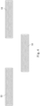
- Fig. 1 is a diagram illustrating a structure of the coater 10 in accordance with one implementation of the present invention
- Fig. 2 is a diagram illustrating a schematic structure of the coater 10.
- the coater 10 includes a coating robot 20, a paint supply unit 40 and a head unit 50.
- the coating robot 20 is mainly comprised of a base 21, a leg 22, a rotating shaft 23, a rotating arm 24, a first swivel arm 25, a second swivel arm 26, a wrist 27 and motors M1-M6 for driving the above parts.
- the base 21 is arranged on a mounting location, such as ground, but also can move relative to the mounting location.
- the leg 22 is set vertically upwards from the base 21.
- a joint may also be disposed between the leg 22 and the base 21 to allow the leg 22 to rotate relative to the base 21.
- an upper end of the leg 22 is provided with the rotating shaft 23. Further, the parts from the rotating shaft 23 to the wrist 27 correspond to a robot arm for moving the head unit 50.
- the rotating arm 24 is mounted on the rotating shaft 23 in such a manner that the rotating arm 24 can rotate freely via the shaft. It should be pointed out that the rotating arm 24 can be driven by the motor M1 to rotate and the motor M1 may be an electric motor or a pneumatic motor. Moreover, the motor M1 may be disposed within a housing of the rotating arm 24, or may be arranged within a housing of the rotating shaft 23. The motor M1, when being an electric one, is preferably disposed within the housing of the rotating shaft 23 or the rotating arm 24 and internal pressure of the housing is increased to avoid explosion (which is the same for the respective motors M2-M6).
- One end of the first swivel arm 25 is rotatably mounted on the rotating arm 24. Furthermore, the motor M2, which causes the first swivel arm 25 to rotate relative to the rotating shaft 23, may be received either within the housing of the rotating arm 24, or within the housing of the first swivel arm 25.
- One end of the second swivel arm 26 is mounted on a further end of the first swivel arm 25 in such a manner that the second swivel arm may swing freely via a shaft.
- the motor M3, which causes the second swivel arm 26 to rotate relative to the first swivel arm 25, may be received either within the housing of the first swivel arm 25, or within the housing of the second swivel arm 26.
- a further end of the second swivel arm 26 is provided with the wrist 27, which can rotate around a plurality of (e.g., three) shafts in different directions. Therefore, the direction of the nozzle head unit 50 can be controlled with high precision. Besides, the number of shafts can be any as long as it is more than two.
- Motors M4-M6 are provided to implement rotating movement of the above wrist 27 around each of the shafts.
- the motors M4-M6 may be received within the housing of the second swivel arm 26, or at other positions.
- the nozzle head unit 50 is mounted on the wrist 27 via a holder 30.
- the nozzle head unit 50 may be assembled to or disassembled from the wrist 27 freely via the holder 30.
- the above coater 10, including the rotating shaft 23, the rotating arm 24, the first swivel arm 25, the second swivel arm 26, the wrist 27 and the motors M1-M6 for driving the above parts, is a robot driven by 6 shafts.
- the coater 10 may be a robot driven by more than four shafts.
- a paint supply unit 40 is provided in the coater 10.
- the paint supply unit 40 supplies the paint for the nozzle head unit 50 and includes supply lines, pumps and valves for supplying the paint.
- a paint storage may be provided external to the coating robot 20 instead of being included therein.
- nozzle head unit 50 is illustrated next.
- the nozzle head unit 50 is mounted on the wrist 27 via the holder 30.
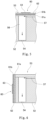
- Fig. 3 is a diagram illustrating a state of a nozzle spray surface 52 for spraying paint in the nozzle head unit 50 when viewed from the front.
- the nozzle spray surface 52 includes an individual nozzle head 53.
- the nozzle spray surface 52 also may be set as a head group comprised of a plurality of nozzle heads 53.
- the plurality of nozzle heads 53 for example, may be staggered as shown in Fig. 4 , but the configuration of the nozzle heads 53 in the head group also may be non-staggered.
- the nozzle head 53 is provided with a plurality of nozzles 54. Besides, a plurality of nozzle columns 55, in which the above nozzles 54 are connected along a specified direction, is provided on the nozzle head 53.
- Fig. 5 is a section view of a schematic structure of the nozzle head 53. As shown, a nozzle compression chamber 56 is arranged in the nozzle head 53 for each nozzle 54 and is connected to a paint supply path 57 used for supplying the paint. The nozzle compression chamber 56 is in communication with the nozzle 54 to spray the paint from each nozzle 54 by driving a piezoelectric substrate 60 described hereinafter to spray the paint.
- the piezoelectric substrate 60 is disposed at a top face (opposite to the nozzle 54) of the nozzle compression chamber 56.
- the piezoelectric substrate 60 includes two piezoelectric ceramic layers 61a and 61b as piezoelectrics, a common electrode 62 and an individual electrode 63.
- the piezoelectric ceramic layers 61a and 61b are scalable by applying voltage from the outside.
- the piezoelectric ceramic layers 61a and 61b may be made of ceramic materials like lead zirconate titanate (PZT) series, NaNbO3 series, BaTiO3 series, (BiNa) NbO3 series and BiNaNb5O15 series with strong dielectricity.
- PZT lead zirconate titanate
- the common electrode 62 is disposed between the piezoelectric ceramic layers 61a and 61b.
- a surface electrode (not shown) for use by the common electrode is formed on the upper surface of the piezoelectric substrate 60.
- the common electrode 62 and the surface electrode for use by the common electrode are electrically connected by a penetrating conductor (not shown) in the piezoelectric ceramic layer 61a.
- the individual electrode 63 is configured at a position opposite to the above nozzle compression chamber 56. A part of the piezoelectric ceramic layer 61a sandwiched by the common electrode 62 and the individual electrode 63 is polarized in a thickness direction.
- the piezoelectric ceramic layer 61a deforms due to piezoelectric effect.
- the piezoelectric ceramic layer 61b projects towards the nozzle compression chamber 56 to spray the paint.
- the common electrode 62 is not limited to the structure of being arranged at the top face of the nozzle compression chamber 56.
- a structure of being disposed at a side face of the nozzle compression chamber 56 illustrated in Fig. 6 also can be adopted.
- the piezoelectric substrate 60 of this implementation may change the applied driving voltage to vary the droplet size of the paint sprayed from the nozzle 54.
- the piezoelectric substrate 60 can generate at least two sizes of droplets through changing the driving voltage. Sometimes, there are for example 7 droplet sizes generated. But it is also possible that only one size or more than two sizes are generated.
- the piezoelectric substrate 60 corresponds to a nozzle driving mechanism.
- the nozzle driving mechanism also may correspond to components other than the piezoelectric substrate 60.
- a component driven for spraying the paint from the nozzle head 53 corresponds to the nozzle driving mechanism.
- a heater for heating the paint in the nozzle compression chamber 56 corresponds to the nozzle driving mechanism.
- a valve and a component driving the valve correspond to the nozzle driving mechanism.
- the control structure of the coater 10 is illustrated below with reference to Fig. 2 .
- the coater 10 includes an image processing unit 70, an arm control unit 80, a paint supply control unit 90, a head control unit 100 and a master control unit 110 and these components correspond to a coating control unit.
- the above components e.g., the paint supply control unit 90
- the coating control unit does not correspond to the coating control unit.
- various sensors which are omitted in the drawings are also included in the coater 10. Outputs from various sensors are input into some one of the arm control unit 80, the paint supply control unit 90, the head control unit 100 and the master control unit 110.
- the various sensors may include an accelerator sensor, an angular velocity sensor, a position detecting sensor for detecting positions of each drive part and an image sensor etc. Sensors except for the above listed ones also can be used.
- the image processing unit 70 in the above control structure handles image data processing based on the size of the coating object, such as vehicle or vehicle parts, when the nozzle head 51 is in a state of spraying the paint.
- the image processing unit 70 for example corresponds to the computer, which may be a part of the coater 10 or arranged separately from the coater 10.
- the image processing unit 70 is arranged separately from the coater 10
- data are received and transmitted via wired or wireless communications between the image processing unit 70 and the coater 10.
- the image processing unit 70 even if the image processing unit 70 is arranged separately from the coater 10, it may be included in the concept of the coater 10 or not.
- the image processing unit 70 specifically produces image data D1 including a normal coating data region R1, an overlapping data region R2 and a non-spraying data region R3 as shown in Fig. 7 every time the nozzle head unit 50 scans the coating object (for each pass).
- image data D1 including a normal coating data region R1, an overlapping data region R2 and a non-spraying data region R3 as shown in Fig. 7 every time the nozzle head unit 50 scans the coating object (for each pass).
- two originally aligned image data D1 for a given pass P1 and its subsequent pass P2 are staggered for display to facilitate explanation.
- the normal coating data region R1 is a partial region of the image data D1 for performing a normal coating on the coating object.
- the overlapping data region R2 is a partial region of the image data D1 for performing the coating such that the attached parts of the paint between neighboring passes overlap.
- the non-spraying data region R3 is a partial region of the image data D1 outside of the end of the coating object without the need of being sprayed with paint.
- a pixel value of each pixel for example is set to 0, such that the nozzle 54 sprays the ink to obtain an expected film thickness.
- the pixel value 0 corresponds to spraying the paint in an expected film thickness.
- the maximum value obtained in the Grayscale also may correspond to spraying the paint in an expected film thickness.
- the maximum pixel value 8 of 8 Grayscale, the maximum pixel value 16 of 16 Grayscale and the maximum pixel value 256 of 256 Grayscale may correspond to spraying the paint in an expected film thickness.
- the maximum value or minimum value (0) in Grayscale for example also may correspond to spraying the paint in a thickness substantially greater than the expected film thickness.
- a desired pixel value (indicated as target pixel value below) between the maximum pixel value and the minimum pixel value of each pixel is defined as coating with an expected film thickness. Therefore, even if performed with the target pixel value, the coating also may be executed at the side of the nozzle head unit 50 with surplus capacity. Accordingly, for example, in accordance with the market where the vehicle is manufactured and sold, it is easy to perform the coating which is set to an appropriate thickness.
- the nozzle columns 55 in the nozzle spray surface 52 are tilted with respect to the scanning direction (pass direction). Therefore, in the image processing unit 70, the respective nozzles 54 preferably spray the paint after reaching a spray starting position of the coating object and the normal coating data region R1 and the overlapping data region R2 are shifted in the scanning direction for each of the nozzles 54, so as to produce the image data D1.
- the pixel values of the respective pixels are set to specified intermediate value in the overlapping data region R2 by the image processing unit 70.
- the two image data D1 of the adjacent passes include an overlapping data region (one-end overlapping data region) R21 and a further overlapping data region (other-end overlapping data region) R22 which overlap with each other
- a pixel value corresponding to about half of the coating film thickness to be formed sometimes is set in the overlapping data region R21 and a pixel value corresponding to about half of the coating film thickness to be formed is also set in the further overlapping data region R22.
- the one-end overlapping data region R21 in the previous pass and the other-end overlapping data region R22 in the subsequent pass overlap with each other.
- the pixel value of the one-end overlapping data region R21 and the pixel value of the other-end overlapping data region R22 are respectively set, such that the coating film of the one-end overlapping data region R21 in the previous pass is formed thicker than that of the other-end overlapping data region R22 in the subsequent pass in one example not encompassed by the wording of the claims but useful for understanding embodiments described herein.
- the pixel value of the one-end overlapping data region R21 and the pixel value of the other-end overlapping data region R22 are respectively set, such that the coating film of the one-end overlapping data region R21 in the previous pass is formed thinner than that of the other-end overlapping data region R22 in the subsequent pass in one example not encompassed by the wording of the claims but useful for understanding embodiments described herein.
- a pixel value (such as maximum pixel value) corresponding to not spraying the paint is set in the non-spraying data region R3.
- the size of the image data D1 in the pass direction (operation direction) is preferably produced to minimize the area of the non-spraying data region R3 as much as possible.
- the image data D1 at a position like an end side of the vehicle, only include either the one-end overlapping data region R21 or the other-end overlapping data region R22.
- the arm control unit 80 is provided for controlling the driving of the above motors M1-M6.
- the arm control unit 80 includes a memory 81 which stores programs and data produced via robot teaching. Besides, in the arm control unit 80, the driving of the motors M1-M6 is controlled based on the programs and data stored in the memory 81 and the image processing in the image processing unit 70. Because of the above control, the nozzle head unit 50 can go through an expected position for executing the coating at a desired speed and stop at a specified position.
- the memory 81 also may be arranged inside the coater 10 or external to the coater 10 to receive and transmit the information via wired or wireless communications.
- the paint supply control unit 90 controls paint supply to the nozzle head unit 50 and specifically controls operation of the pumps and values included in the paint supply unit 40. At this time, the paint supply control unit 90 controls the operation of the above pumps and values preferably by supplying the paint at a constant pressure (quantitative approach as an example) to the nozzle head unit 50. Besides, a head control unit 100 controls the operation of the piezoelectric substrate 60 in the nozzle head unit 50 based on the image processing of the image processing unit 70.
- the master control unit 100 transmits specified control signals to the above arm control unit 80, paint supply control unit 90 and head control unit 100 in such a way that the above motors M1-M6, the paint supply unit 40 and the piezoelectric substrate 60 cooperate to coat the coating object.
- the image data D1 is produced on the basis of the measured sizes of the coating object, wherein the image data D1 is produced respectively for each pass of the scanning of the nozzle head unit 50.
- the produced image data D1 includes the normal coating data region Rl, the overlapping data region R2 and the non-spraying data region R3 as mentioned above.
- the master control unit 110 sends, based on the image data D1 produced by the image processing unit 70, control signals to the arm control unit 80, the paint supply control unit 90 and the head control unit 100 for executing the coating.
- the arm control unit 80 enables at least one of the motors M1-M6 to drive at a specified speed, so as to coat the coating object.
- the paint supply control unit 90 detects, via the sensors not shown, that the nozzle head unit 50 reaches a specified position relative to the coating object, a given nozzle 54 of the nozzle head unit 50 starts to spray the paint.
- the head control unit 100 controls driving of the piezoelectric substrate 60 of the respective nozzles 54 by allowing the nozzles to sequentially spray the paint starting from the nozzle 54 arriving at the end of the coating object. Therefore, a coating surface C is formed on the coating object as shown in Fig. 8 .
- This coating surface C is formed by scanning a plurality of segmented coating surfaces CD coated in each scanning (pass) and overlapping parts of the adjacent segmented coating surfaces CD.
- a normal coating region CR1 is formed by spraying the paint corresponding to the normal coating data region R1 and an overlapping coating region CR2 is formed by spraying the paint corresponding to the overlapping data region R2.
- an one-end overlapping coating region CR21 of the segmented coating surface CD corresponding to the one-end overlapping region R21 and an other-end overlapping coating region CR22 of the segmented coating surface CD corresponding to the other-end overlapping coating region R22 in the previous pass P1 are mixed.
- the one-end overlapping coating region CR21 may overlap the overlapping coating region CR2.
- the overlapping coating region CR2 is in a state of spraying less paint than the normal coating region CR1.
- Fig. 9 is a section view of an overlapping state between the one-end overlapping coating region CR21 and the other-end overlapping coating region CR22.
- an average thickness of the normal coating region CR1 is set to T1 in the previous pass P1 and the subsequent pass P2.
- a total thickness T4 of a thickness T2 of the one-end overlapping coating region CR21 and a thickness T3 of the other-end overlapping coating region CR22 overlapping with the one-end overlapping coating region CR21 is set to be equal to or substantially equal to the thickness T1.
- the subdivided coating regions are adjoined in embodiments described herein, which also corresponds to mixing.
- the thickness of the coating film of the respective subdivided coating regions is also equal to the above T1.
- the head control unit 100 controls the paint spray according to the third coating control based on the image data D1.
- the first coating control and the second coating control are mere examples useful for understanding the invention but are not encompassed by the wording of the claims.
- the first coating control is performed in such a way that droplet size of the paint sprayed from the nozzle 54 in the one-end overlapping coating region CR21 and the other-end overlapping coating region CR22 is smaller than that in the normal coating region CR1.
- the painting is executed in such a way that a sum of a volume of small-sized droplets sprayed in the one-end overlapping coating region CR21 and a volume of small-sized droplets sprayed in the other-end overlapping coating region CR22 equals to a volume of large-sized droplets sprayed in the normal coating region CR1.
- the volume of a sphere usually is in direct proportion to the cube of the radius and the surface area of the sphere is directly proportional to the square of the radius. Therefore, as the radius becomes smaller, some components (organic solvent etc.) included in the paint droplet tend to disperse outwards. Furthermore, of solidified components constituting the coating film in the paint excluding the organic solvent, the total volume of the solidified components in the one-end overlapping coating region CR21 and the other-end overlapping coating region CR22 should be equal to the volume of the solidified components in the normal coating region CR1.
- a radius E1 of the droplet sprayed in the one-end overlapping coating region CR21 is greater than a radius E2 of the droplet sprayed in the other-end overlapping coating region CR22.
- the image data D1 of each pass also may be produced in the image processing unit 70 by arranging the one-end overlapping data region R21 corresponding to the radius E1 of the droplet in the previous pass P1 and arranging the other-end overlapping coating region CR22 corresponding to the radius E2 of the droplet in the subsequent pass P2.
- the image data D1 of each pass are half-toned in the image processing unit 70 or the head control unit 100.
- the halftone processing may be performed by dithering or error diffusion.
- error diffusion, dithering and concentration patterning also can be used in the halftone processing.
- Fig. 10 is a diagram illustrating an example of the halftone processing in the overlapping data region R2. It should be pointed out that various numbers in the matrix of Fig. 10 represent the size of the paint droplet (dot) and the dot size gets bigger as the number increases.
- a dot of a third size sorted in a descending order in an interested pixel is set to ON
- a dot of a sixth size in a pixel adjacent to the interested pixel on the left is set to ON
- a dot of a second size in a pixel to the left diagonal of the interested pixel is set to ON
- a dot in a pixel above the interested pixel is set to OFF (0) as shown in Fig. 10 , and so on.
- the dot size is determined for each pixel.
- the piezoelectric substrate 60 is driven, based on the image processing, to spray droplets from the nozzle 54 relative to the coating object. Therefore, the coating is performed with dot sizes dispersed especially in the overlapping data region R2. After the paint is applied to the coating object, the paint flows to the surroundings to form a coating film of the specified thickness.
- the dot size preferably is the maximum size or a value approximate to the maximum size in the normal coating data region R1 as shown in Fig. 11 .
- the image processing is performed preferably by arranging large-sized dots next to or around the small-sized dots.
- the normal coating region CR1 based on the normal coating data region R1 can form a coating film of the above thickness T1.
- the one-end overlapping coating region CR21 based on the one-end overlapping data region R21 can form a coating film of the above thickness T2
- the other-end overlapping coating region CR22 based on the other-end overlapping data region R22 can form a coating film of the above thickness T3.
- the droplets (dots) of the paint sprayed from the nozzle 54 are set to the same size in the second coating control to form the coating film.
- the expected film thickness is achieved by changing the number of dots sprayed into a certain region.
- the number of dots sprayed from the nozzle 54 per unit area is changed by varying the frequency for driving the piezoelectric substrate 60.
- the droplet (dot) size has 7 levels
- the dot of a given size is sprayed to form the normal coating region CR1 and the overlapping coating region CR2.
- the droplets (dots) of the third level or the fourth level size may be sprayed for reducing the coating time and lowering complexity of the coating control.
- the number of dots sprayed per unit area of the coating object in the normal coating region CR1 on the basis of the normal coating data region R1 is set to D1.
- the number of dots sprayed per unit area of the coating object in the overlapping data region R2 is set to D2.
- the normal coating region CR1 and the overlapping coating region CR2 are respectively formed by setting D1>D2.
- the number of dots sprayed per unit area of the coating object in the one-end overlapping coating region CR21 is set to D21 while the number of dots sprayed per unit area of the coating object in the in the other-end overlapping coating region CR22 is set to D22.
- the thickness T2 of the coating film in the overlapping coating region CR21 and the thickness T3 of the coating film in the other-end overlapping coating region CR22 also may be smaller than the thickness T1 of the coating film in the normal coating region CR1. Accordingly, when the overlapping coating region CR21 overlaps the other-end overlapping coating region CR22, the coating film of a thickness identical to the thickness T1 in the normal coating region CR1 also can be formed in a three dimensional way.
- the area of the overlapping data region R2 (overlapping coating region CR2) is expanded in the third coating control according to embodiments described herein.
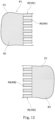
- a data region R4 for subdivision shown in Figs. 12-14 is produced by expanding the area.
- a data region R41 for one-end subdivision is produced in one-end overlapping data region R21 of the previous pass P1 while a data region R42 for other-end subdivision is produced in the other-end overlapping coating region CR22 of the subsequent pass P2.
- the overlapping coating region CR2 of the uniform thickness can be formed by combining the data region R41 for one-end subdivision with the data region R42 for other-end subdivision.
- Fig. 12 a diagram illustrating a state where the data region R41 for one-end subdivision and the data region R42 for other-end subdivision are provided in a comb like shape.
- the coating is executed based on the image data D1 shown in Fig. 12 , it changes to the state shown in Fig. 15 .
- the coating part corresponding to the data region R41 for one-end subdivision is an one-end subdivided coating region R41 and the coating part corresponding to the data region R42 for other-end subdivision is an other-end subdivided coating region CR42.
- the one-end subdivided coating region R41 and the other-end subdivided coating region CR42 are adjoined, rather than overlapping with each other in the thickness direction. Therefore, the one-end subdivided coating region CR41 and the other-end subdivided coating region CR42 are engaged with each other in a comb-like shape.
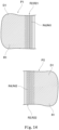
- Fig. 13 is a diagram illustrating a state where the data region R41 for one-end subdivision and the data region R42 for other-end subdivision are provided in a mesh shape.
- the coating is executed based on the image data D1 in Fig. 13 , it changes to the state shown by Fig. 16 , in which the one-end subdivided coating region CR41 and the other-end subdivided coating region CR42 are configured in a checkered pattern, rather than overlapping with each other.
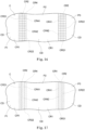
- Fig. 14 is a diagram illustrating a state where the data region R41 for one-end subdivision and the data region R42 for other-end subdivision are provided in a gradation form.
- the coating is executed based on the image data D1 in Fig. 14 , it changes to the state shown by Fig. 17 , in which the one-end subdivided coating region CR41 and the other-end subdivided coating region CR42 respectively change to gradation patterns without overlapping with each other.
- the coating is performed on the coating object based on the image data D1 in which the data region R4 for subdivision exists in the overlapping data region R2, the respective subdivided coating regions CR4 have the thickness of T1. Therefore, the coating is performed with a uniform thickness of T1 in the overlapping coating region CR2.
- the coating object is coated integrally by repeatedly scanning the nozzle head unit 50 with any one of the first coating control, the second coating control and the third coating control or combinations thereof and simultaneously spraying the paint from the nozzle 54 during the scanning.
- the coating control unit controls the execution of the coating on the coating object by repeating scanning of the nozzle head unit for a plurality of times in a state of being divided into segmented coating surfaces CD formed by each scanning of the nozzle head unit50.
- the coating control unit performs the coating by forming a normal coating region CR1 and an overlapping coating region CR2 in the segmented coating surfaces CD, wherein the coating is performed in the normal coating region CR1 so as to have a target coating film thickness Tl, and the coating is performed in the overlapping coating region CR2 in a state where a spray amount of the paint is reduced compared to the normal coating region CR1.
- the coating control unit mixes the overlapping coating region CR2 in the segmented coating surface CD to be coated in the next scan with the overlapping coating region CR2 in the segmented coating surface CD coated in the previous scan and takes the coating film thickness of the mixed overlapping coating region CR2 as the target coating film thickness to perform the coating.
- the thickness of the coating film in the overlapping coating region CR2 where the coating position (segmented coating surface CD) in the previous scan is mixed with the coating position (segmented coating surface CD) in the next scan can be set identical to the thickness of the normal coating region CR1.
- the coating over the entire coating surface C thus can be highly smoothed, which can prevent the bulge induced by the coating position (segmented coating surface CD) in the previous scan overlapping with the coating position (segmented coating surface CD) in the next scan from damaging smoothness.
- the driving of the piezoelectric substrate 60 (nozzle driving mechanism) and of the motors M1-M6 (arm driving mechanism) may also be controlled, to allow the overlapping coating region CR2 of the segmented coating surface CD to be coated in the next scan to overlap the overlapping coating region CR2 of the segmented coating surface CD coated in the previous scan in the thickness direction, thereby coating the target with coating film thickness.
- this position is also coated to serve as the target coating film thickness T1, thereby coating the entire coating surface C at a high level of smoothness.
- the driving of the piezoelectric substrate 60 may also be controlled, such that the paint sprayed from the nozzle 54 in the overlapping coating region CR2 has a smaller droplet size than the paint sprayed in the normal coating region CR1.
- the droplet of the paint sprayed from the nozzle 54 may be optimized to the minimum size, even if the overlapping coating regions CR2 in the previous and next scans overlap, this position is also coated to serve as the target coating film thickness T1, thereby coating the entire coating surface C at a high level of smoothness.
- the driving of the nozzle driving mechanism may also be controlled, such that the number of droplets of the paint sprayed per unit area of the coating object in the overlapping coating region CR2 is less than that in the normal coating region CR1.
- the number of droplets (dots) sprayed from the nozzle 54 may be adjusted to an optimal number less than the normal coating region CR1, even if the overlapping coating regions CR2 in the previous and next scans overlap, this position is also coated to serve as the target coating film thickness T1, thereby coating the entire coating surface C at a high level of smoothness.
- the thickness of the coating film can be calculated proportionally and therefore be easily controlled.
- the coating is controlled by arranging a plurality of subdivided coating regions CR4 in the overlapping coating region CR2 and by placing the subdivided coating region CR4 in the overlapping coating region CR2 formed in the previous scan adjacent to the subdivided coating region CR4 in the overlapping coating region CR2 formed in the next scan.
- the subdivided coating region CR4 formed in the previous scan and the subdivided coating region CR4 formed in the next scan are adjoined, rather than overlapping with each other. Therefore, the amount of paint sprayed from the nozzle 54 is adjusted to perform the coating with the coating film thickness T1 as the target in the overlapping coating region CR2, thereby coating the entire coating surface C at a high level of smoothness.
- the thickness T2 of the one-end overlapping coating region CR21 for example has a substantially the same thickness in its width direction and the thickness T3 of the other-end overlapping coating region CR22 also has a substantially the same thickness in its width direction.
- the thickness of the one-end overlapping coating region CR21 and the other-end overlapping coating region CR22 may also be non-uniform.
- the coating is performed in such a way that the thickness gradually decreases with an increase of distance from the normal coating region CR1 in the one-end overlapping coating region CR21 of the previous pass P1 as shown in Fig. 18 .
- the coating is also performed in such a way that the thickness gradually decreases with an increase of distance from the normal coating region CR1 in the other-end overlapping coating region CR22 of the subsequent pass P2.
- the coating is executed for example using the method of changing dot size in the above first coating control, wherein the dot size decreases with an increase of distance from the respective normal coating regions CR1.
- the coating is executed using the method of changing the number of droplets (dots) sprayed per unit area in the above second coating control, wherein the number of droplets (dots) sprayed decreases with an increase of distance from the respective normal coating regions CR1.
- the coating is performed in such a way that the thickness decreases periodically with an increase of distance from the normal coating region CR1 in the one-end overlapping coating region CR21 of the previous pass P1 as shown in Fig. 19 .
- the coating is also performed in such a way that the thickness decreases periodically with an increase of distance from the normal coating region CR1 in the other-end overlapping coating region CR22 of the subsequent pass P2.
- the periodical change of the thickness in Fig. 19 also can be implemented using the method of changing dot size in the above first coating control and/or the method of changing the number of droplets (dots) in the second coating control as depicted in the above with reference to Fig. 18 .
- the above implementation also explains the case of forming the coating film of constant thickness.
- the coater 10 and the coating method of the present invention are not limited to forming the coating film of constant thickness.
- the coater 10 and the coating method of the present invention are also applicable.
- the thickness of the coating film as depicted sometimes changes according to the coating position. Even in this case, there is a target coating film thickness for each position. Therefore, the overlapping coating region in the segmented coating surface to be coated in the next scan is mixed with the overlapping coating region in the segmented coating surface coated in the previous scan. The coating film thickness of the mixed overlapping coating region can act as the target coating film thickness to coat each position.
- the third coating control is explained for the overlapping coating region and examples useful for understanding are given in the first coating control and the second coating control.
- at least two of the first, second and third coating control also may be combined for execution.
- the coating may be executed by changing the dot size like the first coating control and changing the number of dots sprayed per unit area like the second coating control simultaneously.
- the coating may also be executed by changing the dot size like the first coating control and forming the subdivided coating region like the third coating control simultaneously.
- the coating may also be executed by changing the number of dots sprayed per unit area like the second coating control and forming the subdivided coating region like the third coating control simultaneously.
Description
- The present invention relates to a coater and a coating method.
- In recent years, in coating production lines for vehicles such as automobiles, it has been proposed to coat the vehicles with a coater in an ink-jet fashion, as mentioned in Patent Literature 1. The Patent Literature 1 discloses coating the vehicles by spraying ink from respective nozzles of a nozzle column in a nozzle head.
- Patent Literature 1:
JP patent gazette No. 5976320 US 2019/071912 A1 relates to an applicator of a coating product, a multiaxis robot provided with this applicator and a method for applying a coating product on the surface of a part, such as the hood of a motor vehicle. Patent Literature 3:JP 2016 221958 A - However, the nozzle for spraying ink usually has a width much shorter than the vehicle. Accordingly, in coating the vehicle, it is necessary to gradually change the position of the nozzle head relative to the vehicle and repeatedly scan with the nozzle head simultaneously. In this case, the following issues appear. An end side of the coating region in a previous scan tends to overlap with the coating region in a new scan and this overlapping situation causes differences in the thickness of the coating film formed. This is the main reason that the thickness of the coating film at the overlapping position is different from that at other positions, which degrades the coating quality.
- The present invention is completed based on the above situation and intended to a provide a coater and a coating method for enhancing the coating quality by improving smoothness of a mixed part where the coating position in the previous scan overlaps with the coating position in the next scan.
- To address the above issue, there is provided a coater in accordance with a first aspect of the present invention. The coater coats a coating object by spraying paint from a nozzle in an ink-jet fashion, wherein the coater comprises: a nozzle head unit having a nozzle head formed with a plurality of nozzles at a nozzle spray surface and a nozzle driving mechanism causing the paint to be sprayed from the nozzles; a robot arm having a plurality of arms capable of relatively rotating via shafts and an arm driving mechanism for moving the arms, and configured to move the nozzle head unit in a state of holding the nozzle head unit through driving of the arm driving mechanism; and a coating control unit configured to control driving of the nozzle driving mechanism and driving of the arm driving mechanism to execute coating on the coating object; wherein the coating control unit controls the execution of the coating on the coating object by repeating scanning of the nozzle head unit for a plurality of times in a state of being divided into segmented coating surfaces formed by each scanning of the nozzle head unit; and wherein the coating control unit performs the coating by forming a normal coating region and an overlapping coating region in the segmented coating surfaces, wherein the coating is performed in the normal coating region so as to have a target coating film thickness, and the coating is performed in the overlapping coating region in a state where a spray amount of the paint is reduced compared to the normal coating region; and wherein the coating control unit performs a overlapping coating control by mixing the overlapping coating region in the segmented coating surface to be coated in a next scan with the overlapping coating region in the segmented coating surface coated in a previous scan and taking the coating film thickness of the mixed overlapping coating region as the target coating film thickness to perform coating; and wherein in the overlapping coating control, the coating is controlled by arranging a plurality of subdivided coating regions in the overlapping coating region and by placing the subdivided coating regions in the overlapping coating region formed in the previous scan adjacent to the subdivided coating regions in the overlapping coating region formed in the next scan.
- In accordance with a second aspect of the present invention, there is provided a coating method for coating a coating object by spraying paint from a nozzle in an ink-jet fashion, wherein the coating method comprises: a nozzle head unit having a nozzle head formed with a plurality of nozzles at a nozzle spray surface and a nozzle driving mechanism causing the paint to be sprayed from the nozzles; a robot arm having a plurality of arms capable of relatively rotating via shafts and an arm driving mechanism for moving the arms, and configured to move the nozzle head unit in a state of holding the nozzle head unit through driving of the arm driving mechanism; and a coating control unit configured to control driving of the nozzle driving mechanism and driving of the arm driving mechanism to execute coating on the coating object; wherein the coating on the basis of control of the coating control unit includes: a scanning step in which a plurality of the nozzle head units are caused to scan relative to the coating object; and a segmented coating step in which segmented coating surfaces are formed by spraying the paint from the nozzle relative to the coating object during each scanning step; the segmented coating surfaces include a normal coating region coated with a target coating film thickness and an overlapping coating region coated with a spray amount of the paint less than the normal coating region; the paint is sprayed from the nozzles in such a way that the overlapping coating region in the segmented coating surface to be coated in a next segmented coating step is mixed with the overlapping coating region in the segmented coating surface coated in a previous segmented coating step and the coating film thickness of the mixed overlapping coating region becomes the target coating film thickness; and wherein in the segmented coating step, the coating is controlled by arranging a plurality of subdivided coating regions in the overlapping coating region and by placing the subdivided coating regions in the overlapping coating region formed in the previous scan adjacent to the subdivided coating regions in the overlapping coating region formed in the next scan.
- In accordance with the present invention, there are provided a coater and a coating method for enhancing the coating quality by improving smoothness of a mixed part where the coating position in the previous scan overlaps the coating position in the next scan.
-
-
Fig. 1 is a schematic diagram of an overall structure of an ink-jet coater in accordance with a first implementation of the present invention; -
Fig. 2 is a diagram illustrating a schematic structure of the coater shown inFig. 1 ; -
Fig. 3 is a diagram illustrating a state of a nozzle spray surface for spraying paint in the nozzle head unit of the coater shown inFig. 1 when viewed from the front; -
Fig. 4 is a diagram illustrating a state where the nozzle heads are staggered inFig. 3 ; -
Fig. 5 is a section view of a schematic structure of the nozzle head shown inFig. 3 ; -
Fig. 6 is a section view of a variant of a schematic structure of the nozzle head shown inFig. 5 ; -
Fig. 7 is diagram illustrating images of image data resulted from spraying paint from the nozzle head of the coater shown inFig. 1 ; -
Fig. 8 is a diagram of a coating surface when the coating is executed by the coater shown inFig. 1 , this diagram not being encompassed by the wording of the claims but useful for understanding embodiments described therein; -
Fig. 9 is a section view of a normal coating region and an overlapping coating region in the coating surface shown byFig. 8 ; -
Fig. 10 is a diagram illustrating an example of a dot size of the paint after halftone processing in the overlapping data region of the image data shown byFig. 7 ; -
Fig. 11 is a diagram illustrating an example of a dot size of the paint after halftone processing in the normal coating region of the image data shown byFig. 7 ; -
Fig. 12 is a diagram illustrating comb-like data region for one-end subdivision and data region for other-end subdivision within the overlapping data region of the image data shown byFig. 7 ; -
Fig. 13 is a diagram illustrating mesh-like data region for one-end subdivision and data region for other-end subdivision within the overlapping data region of the image data shown byFig. 7 ; -
Fig. 14 is a diagram illustrating data region for one-end subdivision and data region for other-end subdivision in gradation form within the overlapping data region of the image data shown byFig. 7 ; -
Fig. 15 is a diagram of a coating surface when the coating is executed based on the image data ofFig. 12 ; -
Fig. 16 is a diagram of a coating surface when the coating is executed based on the image data ofFig. 13 ; -
Fig. 17 is a diagram of a coating surface when the coating is executed based on the image data ofFig. 14 ; -
Fig. 18 is a section view of a normal coating region and an overlapping coating region in the coating surface according to a variant of the present invention; -
Fig. 19 a section view of a normal coating region and an overlapping coating region in the coating surface according to a further variant of the present invention. - A
coater 10 and a coating method in accordance with one implementation of the present invention are explained below with reference to the drawings. It should be pointed out that thecoater 10 and the coating method of this implementation are an ink-jet coater and a coating method for the same. Besides, thecoater 10 and the coating method of this implementation "coat" the coating object like vehicle or vehicle parts to form a coating film of a specified thickness on the surfaces of the coating object for the purpose of surface protection and aesthetics. -
Fig. 1 is a diagram illustrating a structure of thecoater 10 in accordance with one implementation of the present invention andFig. 2 is a diagram illustrating a schematic structure of thecoater 10. As shown inFigs. 1 and2 , thecoater 10 includes a coating robot 20, apaint supply unit 40 and ahead unit 50. - The coating robot 20 is mainly comprised of a
base 21, aleg 22, a rotatingshaft 23, a rotatingarm 24, a firstswivel arm 25, a secondswivel arm 26, awrist 27 and motors M1-M6 for driving the above parts. - The
base 21 is arranged on a mounting location, such as ground, but also can move relative to the mounting location. Besides, theleg 22 is set vertically upwards from thebase 21. Moreover, a joint may also be disposed between theleg 22 and thebase 21 to allow theleg 22 to rotate relative to thebase 21. - In addition, an upper end of the
leg 22 is provided with the rotatingshaft 23. Further, the parts from therotating shaft 23 to thewrist 27 correspond to a robot arm for moving thehead unit 50. - The rotating
arm 24 is mounted on the rotatingshaft 23 in such a manner that the rotatingarm 24 can rotate freely via the shaft. It should be pointed out that the rotatingarm 24 can be driven by the motor M1 to rotate and the motor M1 may be an electric motor or a pneumatic motor. Moreover, the motor M1 may be disposed within a housing of the rotatingarm 24, or may be arranged within a housing of the rotatingshaft 23. The motor M1, when being an electric one, is preferably disposed within the housing of the rotatingshaft 23 or the rotatingarm 24 and internal pressure of the housing is increased to avoid explosion (which is the same for the respective motors M2-M6). - One end of the first
swivel arm 25 is rotatably mounted on the rotatingarm 24. Furthermore, the motor M2, which causes the firstswivel arm 25 to rotate relative to the rotatingshaft 23, may be received either within the housing of the rotatingarm 24, or within the housing of the firstswivel arm 25. - One end of the second
swivel arm 26 is mounted on a further end of the firstswivel arm 25 in such a manner that the second swivel arm may swing freely via a shaft. The motor M3, which causes the secondswivel arm 26 to rotate relative to the firstswivel arm 25, may be received either within the housing of the firstswivel arm 25, or within the housing of the secondswivel arm 26. - A further end of the second
swivel arm 26 is provided with thewrist 27, which can rotate around a plurality of (e.g., three) shafts in different directions. Therefore, the direction of thenozzle head unit 50 can be controlled with high precision. Besides, the number of shafts can be any as long as it is more than two. - Motors M4-M6 are provided to implement rotating movement of the
above wrist 27 around each of the shafts. In addition, the motors M4-M6 may be received within the housing of thesecond swivel arm 26, or at other positions. - The
nozzle head unit 50 is mounted on thewrist 27 via a holder 30. In other words, thenozzle head unit 50 may be assembled to or disassembled from thewrist 27 freely via the holder 30. - The
above coater 10, including therotating shaft 23, therotating arm 24, thefirst swivel arm 25, thesecond swivel arm 26, thewrist 27 and the motors M1-M6 for driving the above parts, is a robot driven by 6 shafts. However, thecoater 10 may be a robot driven by more than four shafts. - As shown in
Fig. 2 , apaint supply unit 40 is provided in thecoater 10. Thepaint supply unit 40 supplies the paint for thenozzle head unit 50 and includes supply lines, pumps and valves for supplying the paint. In addition, when the paint is supplied from the outside of the coating robot 20, a paint storage may be provided external to the coating robot 20 instead of being included therein. - The
nozzle head unit 50 is illustrated next. Thenozzle head unit 50 is mounted on thewrist 27 via the holder 30.Fig. 3 is a diagram illustrating a state of anozzle spray surface 52 for spraying paint in thenozzle head unit 50 when viewed from the front. As shown, thenozzle spray surface 52 includes anindividual nozzle head 53. However, thenozzle spray surface 52 also may be set as a head group comprised of a plurality of nozzle heads 53. In this case, the plurality of nozzle heads 53, for example, may be staggered as shown inFig. 4 , but the configuration of the nozzle heads 53 in the head group also may be non-staggered. - The
nozzle head 53 is provided with a plurality ofnozzles 54. Besides, a plurality ofnozzle columns 55, in which theabove nozzles 54 are connected along a specified direction, is provided on thenozzle head 53.Fig. 5 is a section view of a schematic structure of thenozzle head 53. As shown, anozzle compression chamber 56 is arranged in thenozzle head 53 for eachnozzle 54 and is connected to apaint supply path 57 used for supplying the paint. Thenozzle compression chamber 56 is in communication with thenozzle 54 to spray the paint from eachnozzle 54 by driving apiezoelectric substrate 60 described hereinafter to spray the paint. - As shown in
Fig. 5 , thepiezoelectric substrate 60 is disposed at a top face (opposite to the nozzle 54) of thenozzle compression chamber 56. Thepiezoelectric substrate 60 includes two piezoelectricceramic layers common electrode 62 and anindividual electrode 63. The piezoelectricceramic layers ceramic layers - As shown in
Fig. 5 , thecommon electrode 62 is disposed between the piezoelectricceramic layers piezoelectric substrate 60. Thecommon electrode 62 and the surface electrode for use by the common electrode are electrically connected by a penetrating conductor (not shown) in the piezoelectricceramic layer 61a. Moreover, theindividual electrode 63 is configured at a position opposite to the abovenozzle compression chamber 56. A part of the piezoelectricceramic layer 61a sandwiched by thecommon electrode 62 and theindividual electrode 63 is polarized in a thickness direction. Therefore, when the voltage is applied to theindividual electrode 63, the piezoelectricceramic layer 61a deforms due to piezoelectric effect. When a specified drive signal is applied to theindividual electrode 63, the piezoelectricceramic layer 61b projects towards thenozzle compression chamber 56 to spray the paint. - In addition, the
common electrode 62 is not limited to the structure of being arranged at the top face of thenozzle compression chamber 56. For example, a structure of being disposed at a side face of thenozzle compression chamber 56 illustrated inFig. 6 also can be adopted. - Furthermore, the
piezoelectric substrate 60 of this implementation may change the applied driving voltage to vary the droplet size of the paint sprayed from thenozzle 54. To be specific, thepiezoelectric substrate 60 can generate at least two sizes of droplets through changing the driving voltage. Sometimes, there are for example 7 droplet sizes generated. But it is also possible that only one size or more than two sizes are generated. - The
piezoelectric substrate 60 corresponds to a nozzle driving mechanism. However, the nozzle driving mechanism also may correspond to components other than thepiezoelectric substrate 60. For example, when thenozzle head 53 adopts other approaches aside from piezoelectric manner, a component driven for spraying the paint from thenozzle head 53 corresponds to the nozzle driving mechanism. For example, in a thermosensitive (air bubble) scenario, a heater for heating the paint in thenozzle compression chamber 56 corresponds to the nozzle driving mechanism. Additionally, in a valve-related case, a valve and a component driving the valve (solenoid etc.) correspond to the nozzle driving mechanism. - Then, the control structure of the
coater 10 is illustrated below with reference toFig. 2 . As shown, thecoater 10 includes an image processing unit 70, anarm control unit 80, a paintsupply control unit 90, ahead control unit 100 and amaster control unit 110 and these components correspond to a coating control unit. However, it is also possible that at least one of the above components (e.g., the paint supply control unit 90) does not correspond to the coating control unit. - Moreover, various sensors which are omitted in the drawings are also included in the
coater 10. Outputs from various sensors are input into some one of thearm control unit 80, the paintsupply control unit 90, thehead control unit 100 and themaster control unit 110. The various sensors, for example, may include an accelerator sensor, an angular velocity sensor, a position detecting sensor for detecting positions of each drive part and an image sensor etc. Sensors except for the above listed ones also can be used. - The image processing unit 70 in the above control structure handles image data processing based on the size of the coating object, such as vehicle or vehicle parts, when the nozzle head 51 is in a state of spraying the paint. The image processing unit 70 for example corresponds to the computer, which may be a part of the
coater 10 or arranged separately from thecoater 10. When the image processing unit 70 is arranged separately from thecoater 10, data are received and transmitted via wired or wireless communications between the image processing unit 70 and thecoater 10. Besides, even if the image processing unit 70 is arranged separately from thecoater 10, it may be included in the concept of thecoater 10 or not. - With respect to the above image data processing, the image processing unit 70 specifically produces image data D1 including a normal coating data region R1, an overlapping data region R2 and a non-spraying data region R3 as shown in
Fig. 7 every time thenozzle head unit 50 scans the coating object (for each pass). InFig. 7 , two originally aligned image data D1 for a given pass P1 and its subsequent pass P2 are staggered for display to facilitate explanation. - The normal coating data region R1 is a partial region of the image data D1 for performing a normal coating on the coating object. The overlapping data region R2 is a partial region of the image data D1 for performing the coating such that the attached parts of the paint between neighboring passes overlap. The non-spraying data region R3 is a partial region of the image data D1 outside of the end of the coating object without the need of being sprayed with paint.
- In the normal coating data region R1, a pixel value of each pixel for example is set to 0, such that the
nozzle 54 sprays the ink to obtain an expected film thickness. It should be pointed out here that the pixel value 0 corresponds to spraying the paint in an expected film thickness. For example, in Black-White 256 Grayscale, the pixel value corresponds to 0 and the concentration is high in the case of black. However, this invention is not limited to this. For example, the maximum value obtained in the Grayscale also may correspond to spraying the paint in an expected film thickness. For example, the maximum pixel value 8 of 8 Grayscale, the maximum pixel value 16 of 16 Grayscale and the maximum pixel value 256 of 256 Grayscale may correspond to spraying the paint in an expected film thickness. - In addition, the maximum value or minimum value (0) in Grayscale for example also may correspond to spraying the paint in a thickness substantially greater than the expected film thickness. In this case, a desired pixel value (indicated as target pixel value below) between the maximum pixel value and the minimum pixel value of each pixel is defined as coating with an expected film thickness. Therefore, even if performed with the target pixel value, the coating also may be executed at the side of the
nozzle head unit 50 with surplus capacity. Accordingly, for example, in accordance with the market where the vehicle is manufactured and sold, it is easy to perform the coating which is set to an appropriate thickness. - Furthermore, as clearly shown in
Fig. 3 , thenozzle columns 55 in thenozzle spray surface 52 are tilted with respect to the scanning direction (pass direction). Therefore, in the image processing unit 70, therespective nozzles 54 preferably spray the paint after reaching a spray starting position of the coating object and the normal coating data region R1 and the overlapping data region R2 are shifted in the scanning direction for each of thenozzles 54, so as to produce the image data D1. - The pixel values of the respective pixels are set to specified intermediate value in the overlapping data region R2 by the image processing unit 70. In one example not encompassed by the wording of the claims but useful for understanding, when the two image data D1 of the adjacent passes include an overlapping data region (one-end overlapping data region) R21 and a further overlapping data region (other-end overlapping data region) R22 which overlap with each other, a pixel value corresponding to about half of the coating film thickness to be formed sometimes is set in the overlapping data region R21 and a pixel value corresponding to about half of the coating film thickness to be formed is also set in the further overlapping data region R22. Here, the one-end overlapping data region R21 in the previous pass and the other-end overlapping data region R22 in the subsequent pass overlap with each other.
- However, the pixel value of the one-end overlapping data region R21 and the pixel value of the other-end overlapping data region R22 are respectively set, such that the coating film of the one-end overlapping data region R21 in the previous pass is formed thicker than that of the other-end overlapping data region R22 in the subsequent pass in one example not encompassed by the wording of the claims but useful for understanding embodiments described herein. Furthermore, the pixel value of the one-end overlapping data region R21 and the pixel value of the other-end overlapping data region R22 are respectively set, such that the coating film of the one-end overlapping data region R21 in the previous pass is formed thinner than that of the other-end overlapping data region R22 in the subsequent pass in one example not encompassed by the wording of the claims but useful for understanding embodiments described herein.
- Besides, a pixel value (such as maximum pixel value) corresponding to not spraying the paint is set in the non-spraying data region R3. In order to reduce the coating time, the size of the image data D1 in the pass direction (operation direction) is preferably produced to minimize the area of the non-spraying data region R3 as much as possible.
- It should be pointed out that the image data D1, at a position like an end side of the vehicle, only include either the one-end overlapping data region R21 or the other-end overlapping data region R22.
- The
arm control unit 80 is provided for controlling the driving of the above motors M1-M6. Thearm control unit 80 includes a memory 81 which stores programs and data produced via robot teaching. Besides, in thearm control unit 80, the driving of the motors M1-M6 is controlled based on the programs and data stored in the memory 81 and the image processing in the image processing unit 70. Because of the above control, thenozzle head unit 50 can go through an expected position for executing the coating at a desired speed and stop at a specified position. The memory 81 also may be arranged inside thecoater 10 or external to thecoater 10 to receive and transmit the information via wired or wireless communications. - The paint
supply control unit 90 controls paint supply to thenozzle head unit 50 and specifically controls operation of the pumps and values included in thepaint supply unit 40. At this time, the paintsupply control unit 90 controls the operation of the above pumps and values preferably by supplying the paint at a constant pressure (quantitative approach as an example) to thenozzle head unit 50. Besides, ahead control unit 100 controls the operation of thepiezoelectric substrate 60 in thenozzle head unit 50 based on the image processing of the image processing unit 70. - Moreover, the
master control unit 100 transmits specified control signals to the abovearm control unit 80, paintsupply control unit 90 andhead control unit 100 in such a way that the above motors M1-M6, thepaint supply unit 40 and thepiezoelectric substrate 60 cooperate to coat the coating object. - The method for coating the coating object like vehicle or vehicle parts with the
coater 10 of the above structure is illustrated below. - Before coating, the image data D1 is produced on the basis of the measured sizes of the coating object, wherein the image data D1 is produced respectively for each pass of the scanning of the
nozzle head unit 50. At this time, the produced image data D1 includes the normal coating data region Rl, the overlapping data region R2 and the non-spraying data region R3 as mentioned above. - Afterwards, the
master control unit 110 sends, based on the image data D1 produced by the image processing unit 70, control signals to thearm control unit 80, the paintsupply control unit 90 and thehead control unit 100 for executing the coating. In this way, thearm control unit 80 enables at least one of the motors M1-M6 to drive at a specified speed, so as to coat the coating object. Besides, when the paintsupply control unit 90 detects, via the sensors not shown, that thenozzle head unit 50 reaches a specified position relative to the coating object, a givennozzle 54 of thenozzle head unit 50 starts to spray the paint. - At this time, the
head control unit 100 controls driving of thepiezoelectric substrate 60 of therespective nozzles 54 by allowing the nozzles to sequentially spray the paint starting from thenozzle 54 arriving at the end of the coating object. Therefore, a coating surface C is formed on the coating object as shown inFig. 8 . This coating surface C is formed by scanning a plurality of segmented coating surfaces CD coated in each scanning (pass) and overlapping parts of the adjacent segmented coating surfaces CD. - In the above segmented coating surfaces CD, a normal coating region CR1 is formed by spraying the paint corresponding to the normal coating data region R1 and an overlapping coating region CR2 is formed by spraying the paint corresponding to the overlapping data region R2.
- In this implementation, an one-end overlapping coating region CR21 of the segmented coating surface CD corresponding to the one-end overlapping region R21 and an other-end overlapping coating region CR22 of the segmented coating surface CD corresponding to the other-end overlapping coating region R22 in the previous pass P1 are mixed. As an example of the mixing not encompassed by the wording of the claims but useful for understanding embodiments described herein, the one-end overlapping coating region CR21 may overlap the overlapping coating region CR2. Besides, the overlapping coating region CR2 is in a state of spraying less paint than the normal coating region CR1.
- Here, representative structures of the normal coating region CR1 and the overlapping coating region CR2 are depicted in
Fig. 9 , not encompassed by the wording of the claims, but useful for understanding embodiments described therein, which is a section view of an overlapping state between the one-end overlapping coating region CR21 and the other-end overlapping coating region CR22. As shown, an average thickness of the normal coating region CR1 is set to T1 in the previous pass P1 and the subsequent pass P2. By this time, a total thickness T4 of a thickness T2 of the one-end overlapping coating region CR21 and a thickness T3 of the other-end overlapping coating region CR22 overlapping with the one-end overlapping coating region CR21 is set to be equal to or substantially equal to the thickness T1. - Besides that the above one-end overlapping coating region CR21 overlaps with the other-end overlapping coating region CR22 in the example useful for understanding, the subdivided coating regions are adjoined in embodiments described herein, which also corresponds to mixing. In the case where the coating regions after subdivision (subdivided coating regions) are adjoined, the thickness of the coating film of the respective subdivided coating regions is also equal to the above T1.
- In order to form the one-end overlapping coating region CR21 and the other-end overlapping coating region CR22 in an adjoining manner, the
head control unit 100 controls the paint spray according to the third coating control based on the image data D1. In the following, the first coating control and the second coating control are mere examples useful for understanding the invention but are not encompassed by the wording of the claims. - The first coating control is performed in such a way that droplet size of the paint sprayed from the
nozzle 54 in the one-end overlapping coating region CR21 and the other-end overlapping coating region CR22 is smaller than that in the normal coating region CR1. - In such case, the painting is executed in such a way that a sum of a volume of small-sized droplets sprayed in the one-end overlapping coating region CR21 and a volume of small-sized droplets sprayed in the other-end overlapping coating region CR22 equals to a volume of large-sized droplets sprayed in the normal coating region CR1.
- The volume of a sphere usually is in direct proportion to the cube of the radius and the surface area of the sphere is directly proportional to the square of the radius. Therefore, as the radius becomes smaller, some components (organic solvent etc.) included in the paint droplet tend to disperse outwards. Furthermore, of solidified components constituting the coating film in the paint excluding the organic solvent, the total volume of the solidified components in the one-end overlapping coating region CR21 and the other-end overlapping coating region CR22 should be equal to the volume of the solidified components in the normal coating region CR1.
- A time difference is present between the previous pass P1 and the subsequent pass P2. Therefore, to avoid tiny unevenness on the coating film caused by dispersion proportion of the organic solvent, a radius E1 of the droplet sprayed in the one-end overlapping coating region CR21 is greater than a radius E2 of the droplet sprayed in the other-end overlapping coating region CR22. In other words, the image data D1 of each pass also may be produced in the image processing unit 70 by arranging the one-end overlapping data region R21 corresponding to the radius E1 of the droplet in the previous pass P1 and arranging the other-end overlapping coating region CR22 corresponding to the radius E2 of the droplet in the subsequent pass P2.
- Moreover, in the first coating control, the image data D1 of each pass are half-toned in the image processing unit 70 or the
head control unit 100. At this time, the halftone processing may be performed by dithering or error diffusion. In addition, error diffusion, dithering and concentration patterning also can be used in the halftone processing. - In the halftone processing, the paint droplet is converted into an optimal size (dot size) based on the pixel value of each pixel indicating Grayscale. At this time, it may be combined with ON and OFF of the dot.
Fig. 10 is a diagram illustrating an example of the halftone processing in the overlapping data region R2. It should be pointed out that various numbers in the matrix ofFig. 10 represent the size of the paint droplet (dot) and the dot size gets bigger as the number increases. For example, when the dot size has 7 levels, a dot of a third size sorted in a descending order in an interested pixel is set to ON, a dot of a sixth size in a pixel adjacent to the interested pixel on the left is set to ON, a dot of a second size in a pixel to the left diagonal of the interested pixel is set to ON and a dot in a pixel above the interested pixel is set to OFF (0) as shown inFig. 10 , and so on. In this way, the dot size is determined for each pixel. - Besides, in the
head control unit 100, thepiezoelectric substrate 60 is driven, based on the image processing, to spray droplets from thenozzle 54 relative to the coating object. Therefore, the coating is performed with dot sizes dispersed especially in the overlapping data region R2. After the paint is applied to the coating object, the paint flows to the surroundings to form a coating film of the specified thickness. - Moreover, the dot size preferably is the maximum size or a value approximate to the maximum size in the normal coating data region R1 as shown in
Fig. 11 . - Here, in printing on paper or the like, even if the sprayed ink is half-toned, it is also impossible to form a specified thickness on the surface of the printing medium as the ink permeates the printing medium. Besides, in the case where the printing is performed on the printing medium like paper, since the printing relies on the whiteness of the printing medium , it is possible that certain positions cannot be sprayed with ink. However, the paint is formed with a film thickness (three-dimensional state) in the thickness direction in the coating procedure according to this implementation. Moreover, the paint will not permeate the coating object. Therefore, to avoid generating any non-coated regions in the above halftone processing for determining dot size, the image processing is performed preferably by arranging large-sized dots next to or around the small-sized dots.
- When the paint is sprayed from the
nozzle 54 through the above halftone processing, the normal coating region CR1 based on the normal coating data region R1 can form a coating film of the above thickness T1. In addition, the one-end overlapping coating region CR21 based on the one-end overlapping data region R21 can form a coating film of the above thickness T2 and the other-end overlapping coating region CR22 based on the other-end overlapping data region R22 can form a coating film of the above thickness T3. - The droplets (dots) of the paint sprayed from the
nozzle 54 are set to the same size in the second coating control to form the coating film. In this case, the expected film thickness is achieved by changing the number of dots sprayed into a certain region. For example, the number of dots sprayed from thenozzle 54 per unit area is changed by varying the frequency for driving thepiezoelectric substrate 60. For another example, when the droplet (dot) size has 7 levels, the dot of a given size is sprayed to form the normal coating region CR1 and the overlapping coating region CR2. In addition, when the droplet (dot) size has 7 levels, the droplets (dots) of the third level or the fourth level size (sorted in an ascending order) may be sprayed for reducing the coating time and lowering complexity of the coating control. - Here, the number of dots sprayed per unit area of the coating object in the normal coating region CR1 on the basis of the normal coating data region R1 is set to D1. Moreover, the number of dots sprayed per unit area of the coating object in the overlapping data region R2 is set to D2. The normal coating region CR1 and the overlapping coating region CR2 are respectively formed by setting D1>D2.
- The number of dots sprayed per unit area of the coating object in the one-end overlapping coating region CR21 is set to D21 while the number of dots sprayed per unit area of the coating object in the in the other-end overlapping coating region CR22 is set to D22. In this way, the number of dots per unit area of the coating object also may be determined by satisfying the Equation 1 below.

- In such coating, even if the droplet size of the paint is identical, the thickness T2 of the coating film in the overlapping coating region CR21 and the thickness T3 of the coating film in the other-end overlapping coating region CR22 also may be smaller than the thickness T1 of the coating film in the normal coating region CR1. Accordingly, when the overlapping coating region CR21 overlaps the other-end overlapping coating region CR22, the coating film of a thickness identical to the thickness T1 in the normal coating region CR1 also can be formed in a three dimensional way.
- Compared with the examples useful for understanding the invention above first coating control and the second coating control, the area of the overlapping data region R2 (overlapping coating region CR2) is expanded in the third coating control according to embodiments described herein. A data region R4 for subdivision shown in
Figs. 12-14 is produced by expanding the area. Specifically, a data region R41 for one-end subdivision is produced in one-end overlapping data region R21 of the previous pass P1 while a data region R42 for other-end subdivision is produced in the other-end overlapping coating region CR22 of the subsequent pass P2. Besides, the overlapping coating region CR2 of the uniform thickness can be formed by combining the data region R41 for one-end subdivision with the data region R42 for other-end subdivision. - Here,
Fig. 12 a diagram illustrating a state where the data region R41 for one-end subdivision and the data region R42 for other-end subdivision are provided in a comb like shape. When the coating is executed based on the image data D1 shown inFig. 12 , it changes to the state shown inFig. 15 . As shown, the coating part corresponding to the data region R41 for one-end subdivision is an one-end subdivided coating region R41 and the coating part corresponding to the data region R42 for other-end subdivision is an other-end subdivided coating region CR42. Besides, the one-end subdivided coating region R41 and the other-end subdivided coating region CR42 are adjoined, rather than overlapping with each other in the thickness direction. Therefore, the one-end subdivided coating region CR41 and the other-end subdivided coating region CR42 are engaged with each other in a comb-like shape. -
Fig. 13 is a diagram illustrating a state where the data region R41 for one-end subdivision and the data region R42 for other-end subdivision are provided in a mesh shape. When the coating is executed based on the image data D1 inFig. 13 , it changes to the state shown byFig. 16 , in which the one-end subdivided coating region CR41 and the other-end subdivided coating region CR42 are configured in a checkered pattern, rather than overlapping with each other. -
Fig. 14 is a diagram illustrating a state where the data region R41 for one-end subdivision and the data region R42 for other-end subdivision are provided in a gradation form. When the coating is executed based on the image data D1 inFig. 14 , it changes to the state shown byFig. 17 , in which the one-end subdivided coating region CR41 and the other-end subdivided coating region CR42 respectively change to gradation patterns without overlapping with each other. - As described above, when the coating is performed on the coating object based on the image data D1 in which the data region R4 for subdivision exists in the overlapping data region R2, the respective subdivided coating regions CR4 have the thickness of T1. Therefore, the coating is performed with a uniform thickness of T1 in the overlapping coating region CR2.
- The coating object is coated integrally by repeatedly scanning the
nozzle head unit 50 with any one of the first coating control, the second coating control and the third coating control or combinations thereof and simultaneously spraying the paint from thenozzle 54 during the scanning. - In accordance with the
coater 10 of the above structure and the coating method, the coating control unit (image processing unit 70,arm control unit 80, paintsupply control unit 90,head control unit 100 and master control unit 110) controls the execution of the coating on the coating object by repeating scanning of the nozzle head unit for a plurality of times in a state of being divided into segmented coating surfaces CD formed by each scanning of the nozzle head unit50. Besides, the coating control unit performs the coating by forming a normal coating region CR1 and an overlapping coating region CR2 in the segmented coating surfaces CD, wherein the coating is performed in the normal coating region CR1 so as to have a target coating film thickness Tl, and the coating is performed in the overlapping coating region CR2 in a state where a spray amount of the paint is reduced compared to the normal coating region CR1. Moreover, the coating control unit mixes the overlapping coating region CR2 in the segmented coating surface CD to be coated in the next scan with the overlapping coating region CR2 in the segmented coating surface CD coated in the previous scan and takes the coating film thickness of the mixed overlapping coating region CR2 as the target coating film thickness to perform the coating. - Therefore, the thickness of the coating film in the overlapping coating region CR2 where the coating position (segmented coating surface CD) in the previous scan is mixed with the coating position (segmented coating surface CD) in the next scan can be set identical to the thickness of the normal coating region CR1. The coating over the entire coating surface C thus can be highly smoothed, which can prevent the bulge induced by the coating position (segmented coating surface CD) in the previous scan overlapping with the coating position (segmented coating surface CD) in the next scan from damaging smoothness.
- Furthermore, in the overlapping coating control of this implementation, the driving of the piezoelectric substrate 60 (nozzle driving mechanism) and of the motors M1-M6 (arm driving mechanism) may also be controlled, to allow the overlapping coating region CR2 of the segmented coating surface CD to be coated in the next scan to overlap the overlapping coating region CR2 of the segmented coating surface CD coated in the previous scan in the thickness direction, thereby coating the target with coating film thickness.
- In the above control situation, even if the overlapping coating regions CR2 in the previous and next scans overlap, this position is also coated to serve as the target coating film thickness T1, thereby coating the entire coating surface C at a high level of smoothness.
- In the overlapping coating control of an example useful for understanding embodiments described herien, the driving of the piezoelectric substrate 60 (nozzle driving mechanism) may also be controlled, such that the paint sprayed from the
nozzle 54 in the overlapping coating region CR2 has a smaller droplet size than the paint sprayed in the normal coating region CR1. - In the above control situation, as the droplet of the paint sprayed from the
nozzle 54 may be optimized to the minimum size, even if the overlapping coating regions CR2 in the previous and next scans overlap, this position is also coated to serve as the target coating film thickness T1, thereby coating the entire coating surface C at a high level of smoothness. - In the overlapping coating control of this implementation, the driving of the nozzle driving mechanism may also be controlled, such that the number of droplets of the paint sprayed per unit area of the coating object in the overlapping coating region CR2 is less than that in the normal coating region CR1.
- In the above control situation, as the number of droplets (dots) sprayed from the
nozzle 54 may be adjusted to an optimal number less than the normal coating region CR1, even if the overlapping coating regions CR2 in the previous and next scans overlap, this position is also coated to serve as the target coating film thickness T1, thereby coating the entire coating surface
C at a high level of smoothness. In addition, since the paint is sprayed from thenozzle 54 with the same droplet size, the thickness of the coating film can be calculated proportionally and therefore be easily controlled. - In the overlapping coating control of this implementation, the coating is controlled by arranging a plurality of subdivided coating regions CR4 in the overlapping coating region CR2 and by placing the subdivided coating region CR4 in the overlapping coating region CR2 formed in the previous scan adjacent to the subdivided coating region CR4 in the overlapping coating region CR2 formed in the next scan.
- In the above control situation, the subdivided coating region CR4 formed in the previous scan and the subdivided coating region CR4 formed in the next scan are adjoined, rather than overlapping with each other. Therefore, the amount of paint sprayed from the
nozzle 54 is adjusted to perform the coating with the coating film thickness T1 as the target in the overlapping coating region CR2, thereby coating the entire coating surface C at a high level of smoothness. - One implementation of the present invention has been described above, but the present invention is not limited to this and may include different variations, which are explained below.
- In the above implementation, the thickness T2 of the one-end overlapping coating region CR21 for example has a substantially the same thickness in its width direction and the thickness T3 of the other-end overlapping coating region CR22 also has a substantially the same thickness in its width direction. However, the thickness of the one-end overlapping coating region CR21 and the other-end overlapping coating region CR22 may also be non-uniform.
- For example, the coating is performed in such a way that the thickness gradually decreases with an increase of distance from the normal coating region CR1 in the one-end overlapping coating region CR21 of the previous pass P1 as shown in
Fig. 18 . Meanwhile, the coating is also performed in such a way that the thickness gradually decreases with an increase of distance from the normal coating region CR1 in the other-end overlapping coating region CR22 of the subsequent pass P2. At this time, in the coating control of the one-end overlapping coating region CR21 and the other-end overlapping coating region CR22, the coating is executed for example using the method of changing dot size in the above first coating control, wherein the dot size decreases with an increase of distance from the respective normal coating regions CR1. Moreover, in the coating control of the one-end overlapping coating region CR21 and the other-end overlapping coating region CR22, the coating is executed using the method of changing the number of droplets (dots) sprayed per unit area in the above second coating control, wherein the number of droplets (dots) sprayed decreases with an increase of distance from the respective normal coating regions CR1. - In the case of the above coating control, as the
nozzle 54 sprays small-sized droplets (dots) of the paint at a side close to the normal coating region CR1, the seams between the segmented coating surfaces CD (between passes) can hardly be identified. - Furthermore, the coating is performed in such a way that the thickness decreases periodically with an increase of distance from the normal coating region CR1 in the one-end overlapping coating region CR21 of the previous pass P1 as shown in
Fig. 19 . Meanwhile, the coating is also performed in such a way that the thickness decreases periodically with an increase of distance from the normal coating region CR1 in the other-end overlapping coating region CR22 of the subsequent pass P2. In this case, the periodical change of the thickness inFig. 19 also can be implemented using the method of changing dot size in the above first coating control and/or the method of changing the number of droplets (dots) in the second coating control as depicted in the above with reference toFig. 18 . - In the above
Figs. 18 and 19 , a part, especially a thin one, in the other-end overlapping coating region CR22 of the subsequent pass P2 overlaps with a thick part in the one-end overlapping coating region CR21 of the previous pass P1 to correct the thickness. - Besides, the above implementation also explains the case of forming the coating film of constant thickness. However, the
coater 10 and the coating method of the present invention are not limited to forming the coating film of constant thickness. For example, when the coating object is depicted according to a certain design, thecoater 10 and the coating method of the present invention are also applicable. - Here, the thickness of the coating film as depicted sometimes changes according to the coating position. Even in this case, there is a target coating film thickness for each position. Therefore, the overlapping coating region in the segmented coating surface to be coated in the next scan is mixed with the overlapping coating region in the segmented coating surface coated in the previous scan. The coating film thickness of the mixed overlapping coating region can act as the target coating film thickness to coat each position.
- In the above implementation, the third coating control is explained for the overlapping coating region and examples useful for understanding are given in the first coating control and the second coating control. However, at least two of the first, second and third coating control also may be combined for execution. For example, the coating may be executed by changing the dot size like the first coating control and changing the number of dots sprayed per unit area like the second coating control simultaneously. In addition, the coating may also be executed by changing the dot size like the first coating control and forming the subdivided coating region like the third coating control simultaneously. Furthermore, the coating may also be executed by changing the number of dots sprayed per unit area like the second coating control and forming the subdivided coating region like the third coating control simultaneously.
- 10: coater; 20: coating robot; 21: base; 22: leg; 23: rotating shaft; 24: rotating arm; 25: first swivel arm; 26: second swivel arm; 27: wrist; 30: holder; 40: paint supply unit; 50: nozzle head unit; 51: head cover; 52: nozzle spray surface; 53: nozzle head; 54: nozzle; 55: nozzle column; 56: nozzle compression chamber; 57: paint supply path; 60: piezoelectric substrate; 61a, 61b: piezoelectric ceramic layer; 62: common electrode; 63: individual electrode; 70: image processing unit; 80: arm control unit; 81: memory; 90: paint supply control unit; 100: head control unit; 110: master control unit; C: coating surface; CD: segmented coating surface; CR1: normal coating region; CR2: overlapping coating region; CR21: one-end overlapping coating region; CR22: other-end overlapping coating region; CR4: subdivided coating region; CR41: one-end subdivided coating region; CR42: other-end subdivided coating region; D1: image data; M1-M6: motor; R1: normal coating data region; R2: overlapping data region; R21: one-end overlapping data region; R22: other-end overlapping data region; R3: non-spraying data region; R4: data region for subdivision; R41: data region for one-end subdivision; R42: data region for other-end subdivision.
Claims (11)
- A coater (10) for coating a coating object by spraying paint from a nozzle in an ink-jet fashion, the coater comprising:a nozzle head unit (50) having a nozzle head (53) formed with a plurality of nozzles (54) at a nozzle spray surface (52) and a nozzle driving mechanism (60) causing the paint to be sprayed from the nozzles;a robot arm (20) having a plurality of arms (24, 25, 26) capable of relatively rotating via shafts and an arm driving mechanism (M1 - M6) for moving the arms, and configured to move the nozzle head unit (50) in a state of holding the nozzle head unit (50) through driving of the arm driving mechanism (M1 - M6); anda coating control unit (70; 80; 90; 100; 110) configured to control driving of the nozzle driving mechanism (60) and driving of the arm driving mechanism (M1 - M6) to execute coating on the coating object;wherein the coating control unit (70; 80; 90; 100; 110) controls the execution of the coating on the coating object by repeating scanning of the nozzle head unit (50) for a plurality of times in a state of being divided into segmented coating surfaces (CD) formed by each scanning of the nozzle head unit (50); andwherein the coating control unit (70; 80; 90; 100; 110) performs the coating by forming a normal coating region (CR1) and an overlapping coating region (CR2; CR21; CR22) in the segmented coating surfaces, wherein the coating is performed in the normal coating region (CR1) so as to have a target coating film thickness, and the coating is performed in the overlapping coating region (CR2; CR21; CR22) in a state where a spray amount of the paint is reduced compared to the normal coating region (CR1);wherein the coating control unit (70; 80; 90; 100; 110) performs an overlapping coating control by mixing the overlapping coating region in the segmented coating surface (CD) to be coated in a next scan with the overlapping coating region (CR2; CR21; CR22) in the segmented coating surface (CD) coated in a previous scan and taking the coating film thickness of the mixed overlapping coating region (CR2; CR21; CR22) as the target coating film thickness (T1) to perform coating; andwherein in the overlapping coating control, the coating is controlled by arranging a plurality of subdivided coating regions (CR4; CR41; CR42) in the overlapping coating region (CR2; CR21; CR22) and by placing the subdivided coating regions (CR4; CR41; CR42) in the overlapping coating region formed in the previous scan adjacent to the subdivided coating regions (CR4; CR41; CR42) in the overlapping coating region (CR2; CR21; CR22) formed in the next scan.
- The coater of claim 1, wherein
the plurality of subdivided coating regions (CR4; CR41; CR42) in the overlapping coating region (CR2; CR21; CR22) include a one-end subdivided coating region (CR41) and a other-end subdivided coating region (CR42) being engaged with each other in a comb-like shape. - The coater according of claim 1, wherein
the plurality of subdivided coating regions (CR4; CR41; CR42) in the overlapping coating region (CR2; CR21; CR22) include a one-end subdivided coating region (CR41) and a other-end subdivided coating region (CR42) provided in a checkered pattern. - The coater according of claim 1, wherein
the plurality of subdivided coating regions (CR4; CR41; CR42) in the overlapping coating region (CR2; CR21; CR22) include a one-end subdivided coating region (CR41) and a other-end subdivided coating region (CR42) provided in a gradation form. - A coating method for coating a coating object by spraying paint from a nozzle (54) in an ink-jet fashion, the coating method comprising:a nozzle head unit (50) having a nozzle head (53) formed with a plurality of nozzles (54) at a nozzle spray surface and a nozzle driving mechanism (60) causing the paint to be sprayed from the nozzles (54);a robot arm (20) having a plurality of arms (24; 25; 26) capable of relatively rotating via shafts and an arm driving mechanism (M1 - M6) for moving the arms, and configured to move the nozzle head unit (50) in a state of holding the nozzle head unit (50) through driving of the arm driving mechanism (M1-M6); anda coating control unit (70; 80; 90; 100; 110) configured to control driving of the nozzle driving mechanism (60) and driving of the arm driving mechanism (M1-M6) to execute coating on the coating object,wherein the coating method on the basis of control of the coating control unit (70; 80; 90; 100; 110) includes:a scanning step in which the nozzle head unit (50) is caused to repeatedly scan for a plurality of times relative to the coating object; anda segmented coating step in which segmented coating surfaces (CD) are formed by spraying the paint from the nozzle (54) relative to the coating object during each scanning step;the segmented coating surfaces (CD) include a normal coating region (CR1) coated with a target coating film thickness (T1) and an overlapping coating region (CR2; CR21; CR22) coated with a spray amount of the paint less than the normal coating region (CR1);the paint is sprayed from the nozzles (54) in such a way that the overlapping coating region (CR2; CR21; CR22) in the segmented coating surface (CD) to be coated in a next segmented coating step is mixed with the overlapping coating region (CR2; CR21; CR22) in the segmented coating surface (CD) coated in a previous segmented coating step and the coating film thickness of the mixed overlapping coating region becomes the target coating film thickness (T1); andwherein in the segmented coating step, the coating is controlled by arranging a plurality of subdivided coating regions (CR4; CR41; CR42) in the overlapping coating region (CR2; CR21; CR22) and by placing the subdivided coating regions (CR4; CR41; CR42) in the overlapping coating region formed in the previous scan adjacent to the subdivided coating regions (CR4; CR41; CR42) in the overlapping coating region (CR2; CR21; CR22) formed in the next scan.
- The coating method of claim 5, whereinthe plurality of subdivided coating regions (CR4; CR41; CR42) in the overlapping coating region (CR2; CR21; CR22) include a one-end subdivided coating region (CR41) and a other-end subdivided coating region (CR42), andwherein in the segmented coating step, the one-end subdivided coating region (CR41) and the other-end subdivided coating region (CR42) are engaged with each other in a comb-like shape.
- The coating method of claim 5, whereinthe plurality of subdivided coating regions (CR4; CR41; CR42) in the overlapping coating region (CR2; CR21; CR22) include a one-end subdivided coating region (CR41) and a other-end subdivided coating region (CR42), andwherein in the segmented coating step, the one-end subdivided coating region (CR41) and the other-end subdivided coating region (CR42) are provided in a checkered pattern.
- The coating method of claim 5, whereinthe plurality of subdivided coating regions (CR4; CR41; CR42) in the overlapping coating region (CR2; CR21; CR22) include a one-end subdivided coating region (CR41) and a other-end subdivided coating region (CR42), andwherein the in the segmented coating step, the one-end subdivided coating region (CR41) and the other-end subdivided coating region (CR42) are provided in a gradation form.
- The coating method according to any of claims 5 to 8, whereinthe plurality of subdivided coating regions (CR4; CR41; CR42) in the overlapping coating region (CR2; CR21; CR22) include a one-end subdivided coating region (CR41) and a other-end subdivided coating region (CR42), and whereina data region (R41) for the one-end subdivided coating region (CR41) is produced in a one-end overlapping data region (R21) of the previous scan and a data region (R42) for the other-end subdivided coating region (CR42) is produced in the other-end overlapping coating region (CR22) of the subsequent scan.
- The coating method according to claim 9, wherein
the data region (R41) for the one-end subdivided coating region (CR41) and the data region (R42) for the other-end subdivided coating region (CR42) are provided in at least one of a comb-like shape, a mesh shape, and a gradation form. - The coating method of claim 5, wherein
in the segmented coating step, the paint is sprayed from the nozzles (54) in such a way that the number of the droplets of the paint sprayed per unit area of the coating object in the overlapping coating region (CR2; CR21; CR22) is less than that in the normal coating region (CR1).
Applications Claiming Priority (1)
| Application Number | Priority Date | Filing Date | Title |
|---|---|---|---|
| PCT/JP2019/025448 WO2020261443A1 (en) | 2019-06-26 | 2019-06-26 | Coating machine and coating method |
Publications (3)
| Publication Number | Publication Date |
|---|---|
| EP3789123A1 EP3789123A1 (en) | 2021-03-10 |
| EP3789123A4 EP3789123A4 (en) | 2021-04-28 |
| EP3789123B1 true EP3789123B1 (en) | 2023-04-26 |
Family
ID=74044365
Family Applications (1)
| Application Number | Title | Priority Date | Filing Date |
|---|---|---|---|
| EP19850781.6A Active EP3789123B1 (en) | 2019-06-26 | 2019-06-26 | Coating machine and coating method |
Country Status (5)
| Country | Link |
|---|---|
| US (1) | US11491788B2 (en) |
| EP (1) | EP3789123B1 (en) |
| JP (1) | JP7285827B2 (en) |
| CN (1) | CN112437698A (en) |
| WO (1) | WO2020261443A1 (en) |
Families Citing this family (4)
| Publication number | Priority date | Publication date | Assignee | Title |
|---|---|---|---|---|
| US11826768B2 (en) * | 2021-03-11 | 2023-11-28 | Ford Global Technologies, Llc | Method and apparatus for adaptive control and real-time edge tracking of adhesive and sealer dispensing |
| JP6948482B1 (en) * | 2021-03-25 | 2021-10-13 | アーベーベー・シュバイツ・アーゲーABB Schweiz AG | Painting robot system and painting method |
| WO2023041161A1 (en) * | 2021-09-16 | 2023-03-23 | Abb Schweiz Ag | Method of applying coating medium, coated object, control system and coating system |
| JP7066035B1 (en) | 2021-11-04 | 2022-05-12 | アーベーベー・シュバイツ・アーゲー | Painting robot |
Family Cites Families (29)
| Publication number | Priority date | Publication date | Assignee | Title |
|---|---|---|---|---|
| JP4231564B2 (en) | 1997-10-23 | 2009-03-04 | オリンパス株式会社 | On-demand coating equipment |
| JPH11245384A (en) * | 1998-02-27 | 1999-09-14 | Canon Inc | Device and method for recording |
| JP3988645B2 (en) * | 2002-03-06 | 2007-10-10 | セイコーエプソン株式会社 | Discharge method, discharge device, color filter manufacturing method, electroluminescence device manufacturing method, and plasma display panel manufacturing method |
| JP4003743B2 (en) * | 2003-12-11 | 2007-11-07 | ブラザー工業株式会社 | Inkjet printer |
| CN100531930C (en) * | 2004-06-01 | 2009-08-26 | Abb株式会社 | Painting method |
| JP4159525B2 (en) | 2004-08-23 | 2008-10-01 | 株式会社石井表記 | Alignment film forming method and ink jet print head ejection inspection device |
| JP4564454B2 (en) * | 2006-01-19 | 2010-10-20 | 東京エレクトロン株式会社 | Coating method, coating apparatus, and coating program |
| JP4389953B2 (en) * | 2007-03-22 | 2009-12-24 | セイコーエプソン株式会社 | Pattern formation method |
| DE102008053178A1 (en) | 2008-10-24 | 2010-05-12 | Dürr Systems GmbH | Coating device and associated coating method |
| EP2199434A1 (en) * | 2008-12-19 | 2010-06-23 | FEI Company | Method for forming microscopic structures on a substrate |
| DE102009004878A1 (en) * | 2009-01-16 | 2010-07-29 | Bauer, Jörg R. | Process for coating, in particular painting, a surface and digital coating system |
| DE102010019612A1 (en) | 2010-05-06 | 2011-11-10 | Dürr Systems GmbH | Coating device, in particular with an application device, and associated coating method that emits a droplets of coating agent droplet |
| JP5688268B2 (en) | 2010-11-08 | 2015-03-25 | 株式会社エルエーシー | Curved surface coating equipment |
| JP5730698B2 (en) * | 2011-07-15 | 2015-06-10 | 株式会社ミマキエンジニアリング | Printing method and printing apparatus |
| JP6198499B2 (en) * | 2013-07-04 | 2017-09-20 | 株式会社エルエーシー | Printing device |
| JP6085578B2 (en) * | 2014-03-11 | 2017-02-22 | 住友重機械工業株式会社 | Film forming method and film forming apparatus |
| US10093111B2 (en) * | 2015-05-27 | 2018-10-09 | Nike, Inc. | Color density based thickness compensation printing |
| US9452616B1 (en) * | 2015-05-29 | 2016-09-27 | The Boeing Company | System and method for printing an image on a surface |
| EP3358913A4 (en) * | 2015-09-30 | 2019-05-15 | Sumitomo Chemical Company, Limited | Thin film production method and organic el device production method |
| JP6695029B2 (en) * | 2015-12-28 | 2020-05-20 | パナソニックIpマネジメント株式会社 | Ink coating device and ink coating method |
| FR3048368A1 (en) * | 2016-03-04 | 2017-09-08 | Exel Ind | COATING PRODUCT APPLICATOR, MULTIAXIS ROBOT COMPRISING SUCH APPLICATOR AND METHOD FOR APPLYING COATING PRODUCT |
| JP6821951B2 (en) | 2016-04-18 | 2021-01-27 | 株式会社リコー | A coating method that forms a coating film with a uniform thickness in multiple adjacent regions. |
| DE102017101336A1 (en) * | 2017-01-25 | 2018-07-26 | Abb Schweiz Ag | spray applicator |
| JP6848486B2 (en) | 2017-01-31 | 2021-03-24 | 株式会社リコー | apparatus |
| WO2019017214A1 (en) * | 2017-07-18 | 2019-01-24 | Abb株式会社 | Painting device |
| CN109574511A (en) | 2017-09-29 | 2019-04-05 | 中外炉工业株式会社 | The coating method of substrate and the apparatus for coating of substrate |
| JP7027796B2 (en) | 2017-10-20 | 2022-03-02 | セイコーエプソン株式会社 | Printing device and printing control device |
| JP2019080278A (en) | 2017-10-27 | 2019-05-23 | セイコーエプソン株式会社 | Image processing apparatus, image processing method, and printing apparatus |
| FR3087704B1 (en) * | 2018-10-26 | 2021-04-30 | Psa Automobiles Sa | SURFACE PRINTING WITH OVERLAPPING STRIPS |
-
2019
- 2019-06-26 JP JP2020511832A patent/JP7285827B2/en active Active
- 2019-06-26 WO PCT/JP2019/025448 patent/WO2020261443A1/en unknown
- 2019-06-26 EP EP19850781.6A patent/EP3789123B1/en active Active
- 2019-06-26 CN CN201980004094.0A patent/CN112437698A/en active Pending
-
2020
- 2020-02-25 US US16/800,339 patent/US11491788B2/en active Active
Also Published As
| Publication number | Publication date |
|---|---|
| JP7285827B2 (en) | 2023-06-02 |
| CN112437698A (en) | 2021-03-02 |
| EP3789123A4 (en) | 2021-04-28 |
| JPWO2020261443A1 (en) | 2021-09-13 |
| US11491788B2 (en) | 2022-11-08 |
| WO2020261443A1 (en) | 2020-12-30 |
| EP3789123A1 (en) | 2021-03-10 |
| US20200406617A1 (en) | 2020-12-31 |
Similar Documents
| Publication | Publication Date | Title |
|---|---|---|
| EP3789123B1 (en) | Coating machine and coating method | |
| KR102007618B1 (en) | Ink-based layer fabrication using halftoning to control thickness | |
| US11679597B2 (en) | Drop-on-demand—coating of surfaces | |
| WO2021205537A1 (en) | Ink-jet type vehicle coating machine and vehicle coating method | |
| JP6535279B2 (en) | Method and apparatus for printing on a three-dimensional surface | |
| JP6948482B1 (en) | Painting robot system and painting method | |
| JP2010184380A (en) | Method of manufacturing fluid ejecting apparatus | |
| WO2021255896A1 (en) | Painting robot and painting method using painting robot | |
| CN108928124A (en) | The adjusting method and recording device of record head | |
| US20240109096A1 (en) | Coating device, coating film, and coating method | |
| EP3194174B1 (en) | Image forming apparatus and image forming method | |
| CN102248815B (en) | Method for detecting adjustment value of fluid ejection device, and fluid eection device | |
| JP7223244B2 (en) | Recording device and recording method | |
| US20220274129A1 (en) | Coating device and coating method | |
| JP2016123942A (en) | Ink jet printing method and ink jet coater | |
| CN109927413A (en) | Membrane formation device and film forming method | |
| JP2010194755A (en) | Manufacturing method of fluid jetting apparatus | |
| JP2017042985A (en) | Ink jet printer | |
| JP2010194754A (en) | Manufacturing method of fluid jetting apparatus | |
| US20220347713A1 (en) | Coating device, coating film, and coating method | |
| JPWO2007132727A1 (en) | Color filter manufacturing method and apparatus | |
| JP4586373B2 (en) | Droplet ejection method | |
| JP5384816B2 (en) | Droplet coating apparatus and droplet coating method | |
| CN117916095A (en) | Method for applying a coating medium, coated object, control system and coating system | |
| JP2020116866A (en) | Recording device and recording method |
Legal Events
| Date | Code | Title | Description |
|---|---|---|---|
| STAA | Information on the status of an ep patent application or granted ep patent |
Free format text: STATUS: UNKNOWN |
|
| STAA | Information on the status of an ep patent application or granted ep patent |
Free format text: STATUS: THE INTERNATIONAL PUBLICATION HAS BEEN MADE |
|
| PUAI | Public reference made under article 153(3) epc to a published international application that has entered the european phase |
Free format text: ORIGINAL CODE: 0009012 |
|
| STAA | Information on the status of an ep patent application or granted ep patent |
Free format text: STATUS: REQUEST FOR EXAMINATION WAS MADE |
|
| 17P | Request for examination filed |
Effective date: 20200226 |
|
| AK | Designated contracting states |
Kind code of ref document: A1 Designated state(s): AL AT BE BG CH CY CZ DE DK EE ES FI FR GB GR HR HU IE IS IT LI LT LU LV MC MK MT NL NO PL PT RO RS SE SI SK SM TR |
|
| AX | Request for extension of the european patent |
Extension state: BA ME |
|
| A4 | Supplementary search report drawn up and despatched |
Effective date: 20210325 |
|
| RIC1 | Information provided on ipc code assigned before grant |
Ipc: B05B 1/14 20060101AFI20210319BHEP Ipc: B41J 2/14 20060101ALI20210319BHEP Ipc: B05B 13/04 20060101ALN20210319BHEP Ipc: B41J 3/407 20060101ALN20210319BHEP |
|
| STAA | Information on the status of an ep patent application or granted ep patent |
Free format text: STATUS: EXAMINATION IS IN PROGRESS |
|
| 17Q | First examination report despatched |
Effective date: 20220524 |
|
| DAV | Request for validation of the european patent (deleted) | ||
| DAX | Request for extension of the european patent (deleted) | ||
| REG | Reference to a national code |
Ref document number: 602019028161 Country of ref document: DE Ref country code: DE Ref legal event code: R079 Free format text: PREVIOUS MAIN CLASS: B05C0005000000 Ipc: B05B0001140000 |
|
| GRAP | Despatch of communication of intention to grant a patent |
Free format text: ORIGINAL CODE: EPIDOSNIGR1 |
|
| STAA | Information on the status of an ep patent application or granted ep patent |
Free format text: STATUS: GRANT OF PATENT IS INTENDED |
|
| RIC1 | Information provided on ipc code assigned before grant |
Ipc: B41J 2/21 20060101ALN20221205BHEP Ipc: B41J 3/407 20060101ALN20221205BHEP Ipc: B05B 13/04 20060101ALN20221205BHEP Ipc: B25J 11/00 20060101ALI20221205BHEP Ipc: B05B 17/06 20060101ALI20221205BHEP Ipc: B05B 12/08 20060101ALI20221205BHEP Ipc: B41J 2/14 20060101ALI20221205BHEP Ipc: B05B 1/14 20060101AFI20221205BHEP |
|
| INTG | Intention to grant announced |
Effective date: 20221222 |
|
| RIC1 | Information provided on ipc code assigned before grant |
Ipc: B41J 2/21 20060101ALN20221209BHEP Ipc: B41J 3/407 20060101ALN20221209BHEP Ipc: B05B 13/04 20060101ALN20221209BHEP Ipc: B25J 11/00 20060101ALI20221209BHEP Ipc: B05B 17/06 20060101ALI20221209BHEP Ipc: B05B 12/08 20060101ALI20221209BHEP Ipc: B41J 2/14 20060101ALI20221209BHEP Ipc: B05B 1/14 20060101AFI20221209BHEP |
|
| GRAS | Grant fee paid |
Free format text: ORIGINAL CODE: EPIDOSNIGR3 |
|
| GRAA | (expected) grant |
Free format text: ORIGINAL CODE: 0009210 |
|
| STAA | Information on the status of an ep patent application or granted ep patent |
Free format text: STATUS: THE PATENT HAS BEEN GRANTED |
|
| RAP3 | Party data changed (applicant data changed or rights of an application transferred) |
Owner name: ABB SCHWEIZ AG |
|
| AK | Designated contracting states |
Kind code of ref document: B1 Designated state(s): AL AT BE BG CH CY CZ DE DK EE ES FI FR GB GR HR HU IE IS IT LI LT LU LV MC MK MT NL NO PL PT RO RS SE SI SK SM TR |
|
| REG | Reference to a national code |
Ref country code: GB Ref legal event code: FG4D |
|
| REG | Reference to a national code |
Ref country code: CH Ref legal event code: EP |
|
| REG | Reference to a national code |
Ref country code: DE Ref legal event code: R096 Ref document number: 602019028161 Country of ref document: DE |
|
| REG | Reference to a national code |
Ref country code: AT Ref legal event code: REF Ref document number: 1562445 Country of ref document: AT Kind code of ref document: T Effective date: 20230515 |
|
| REG | Reference to a national code |
Ref country code: IE Ref legal event code: FG4D |
|
| PGFP | Annual fee paid to national office [announced via postgrant information from national office to epo] |
Ref country code: FR Payment date: 20230628 Year of fee payment: 5 Ref country code: DE Payment date: 20230620 Year of fee payment: 5 Ref country code: CZ Payment date: 20230619 Year of fee payment: 5 |
|
| REG | Reference to a national code |
Ref country code: LT Ref legal event code: MG9D |
|
| REG | Reference to a national code |
Ref country code: NL Ref legal event code: MP Effective date: 20230426 |
|
| REG | Reference to a national code |
Ref country code: AT Ref legal event code: MK05 Ref document number: 1562445 Country of ref document: AT Kind code of ref document: T Effective date: 20230426 |
|
| PG25 | Lapsed in a contracting state [announced via postgrant information from national office to epo] |
Ref country code: NL Free format text: LAPSE BECAUSE OF FAILURE TO SUBMIT A TRANSLATION OF THE DESCRIPTION OR TO PAY THE FEE WITHIN THE PRESCRIBED TIME-LIMIT Effective date: 20230426 |
|
| PG25 | Lapsed in a contracting state [announced via postgrant information from national office to epo] |
Ref country code: SE Free format text: LAPSE BECAUSE OF FAILURE TO SUBMIT A TRANSLATION OF THE DESCRIPTION OR TO PAY THE FEE WITHIN THE PRESCRIBED TIME-LIMIT Effective date: 20230426 Ref country code: PT Free format text: LAPSE BECAUSE OF FAILURE TO SUBMIT A TRANSLATION OF THE DESCRIPTION OR TO PAY THE FEE WITHIN THE PRESCRIBED TIME-LIMIT Effective date: 20230828 Ref country code: NO Free format text: LAPSE BECAUSE OF FAILURE TO SUBMIT A TRANSLATION OF THE DESCRIPTION OR TO PAY THE FEE WITHIN THE PRESCRIBED TIME-LIMIT Effective date: 20230726 Ref country code: ES Free format text: LAPSE BECAUSE OF FAILURE TO SUBMIT A TRANSLATION OF THE DESCRIPTION OR TO PAY THE FEE WITHIN THE PRESCRIBED TIME-LIMIT Effective date: 20230426 Ref country code: AT Free format text: LAPSE BECAUSE OF FAILURE TO SUBMIT A TRANSLATION OF THE DESCRIPTION OR TO PAY THE FEE WITHIN THE PRESCRIBED TIME-LIMIT Effective date: 20230426 |
|
| PGFP | Annual fee paid to national office [announced via postgrant information from national office to epo] |
Ref country code: TR Payment date: 20230713 Year of fee payment: 5 Ref country code: IT Payment date: 20230731 Year of fee payment: 5 Ref country code: GB Payment date: 20230622 Year of fee payment: 5 |
|
| PG25 | Lapsed in a contracting state [announced via postgrant information from national office to epo] |
Ref country code: RS Free format text: LAPSE BECAUSE OF FAILURE TO SUBMIT A TRANSLATION OF THE DESCRIPTION OR TO PAY THE FEE WITHIN THE PRESCRIBED TIME-LIMIT Effective date: 20230426 Ref country code: PL Free format text: LAPSE BECAUSE OF FAILURE TO SUBMIT A TRANSLATION OF THE DESCRIPTION OR TO PAY THE FEE WITHIN THE PRESCRIBED TIME-LIMIT Effective date: 20230426 Ref country code: LV Free format text: LAPSE BECAUSE OF FAILURE TO SUBMIT A TRANSLATION OF THE DESCRIPTION OR TO PAY THE FEE WITHIN THE PRESCRIBED TIME-LIMIT Effective date: 20230426 Ref country code: LT Free format text: LAPSE BECAUSE OF FAILURE TO SUBMIT A TRANSLATION OF THE DESCRIPTION OR TO PAY THE FEE WITHIN THE PRESCRIBED TIME-LIMIT Effective date: 20230426 Ref country code: IS Free format text: LAPSE BECAUSE OF FAILURE TO SUBMIT A TRANSLATION OF THE DESCRIPTION OR TO PAY THE FEE WITHIN THE PRESCRIBED TIME-LIMIT Effective date: 20230826 Ref country code: HR Free format text: LAPSE BECAUSE OF FAILURE TO SUBMIT A TRANSLATION OF THE DESCRIPTION OR TO PAY THE FEE WITHIN THE PRESCRIBED TIME-LIMIT Effective date: 20230426 Ref country code: GR Free format text: LAPSE BECAUSE OF FAILURE TO SUBMIT A TRANSLATION OF THE DESCRIPTION OR TO PAY THE FEE WITHIN THE PRESCRIBED TIME-LIMIT Effective date: 20230727 |
|
| PG25 | Lapsed in a contracting state [announced via postgrant information from national office to epo] |
Ref country code: FI Free format text: LAPSE BECAUSE OF FAILURE TO SUBMIT A TRANSLATION OF THE DESCRIPTION OR TO PAY THE FEE WITHIN THE PRESCRIBED TIME-LIMIT Effective date: 20230426 |
|
| PG25 | Lapsed in a contracting state [announced via postgrant information from national office to epo] |
Ref country code: SK Free format text: LAPSE BECAUSE OF FAILURE TO SUBMIT A TRANSLATION OF THE DESCRIPTION OR TO PAY THE FEE WITHIN THE PRESCRIBED TIME-LIMIT Effective date: 20230426 |
|
| PG25 | Lapsed in a contracting state [announced via postgrant information from national office to epo] |
Ref country code: MC Free format text: LAPSE BECAUSE OF FAILURE TO SUBMIT A TRANSLATION OF THE DESCRIPTION OR TO PAY THE FEE WITHIN THE PRESCRIBED TIME-LIMIT Effective date: 20230426 |
|
| REG | Reference to a national code |
Ref country code: DE Ref legal event code: R097 Ref document number: 602019028161 Country of ref document: DE |
|
| PG25 | Lapsed in a contracting state [announced via postgrant information from national office to epo] |
Ref country code: SM Free format text: LAPSE BECAUSE OF FAILURE TO SUBMIT A TRANSLATION OF THE DESCRIPTION OR TO PAY THE FEE WITHIN THE PRESCRIBED TIME-LIMIT Effective date: 20230426 Ref country code: SK Free format text: LAPSE BECAUSE OF FAILURE TO SUBMIT A TRANSLATION OF THE DESCRIPTION OR TO PAY THE FEE WITHIN THE PRESCRIBED TIME-LIMIT Effective date: 20230426 Ref country code: RO Free format text: LAPSE BECAUSE OF FAILURE TO SUBMIT A TRANSLATION OF THE DESCRIPTION OR TO PAY THE FEE WITHIN THE PRESCRIBED TIME-LIMIT Effective date: 20230426 Ref country code: MC Free format text: LAPSE BECAUSE OF FAILURE TO SUBMIT A TRANSLATION OF THE DESCRIPTION OR TO PAY THE FEE WITHIN THE PRESCRIBED TIME-LIMIT Effective date: 20230426 Ref country code: EE Free format text: LAPSE BECAUSE OF FAILURE TO SUBMIT A TRANSLATION OF THE DESCRIPTION OR TO PAY THE FEE WITHIN THE PRESCRIBED TIME-LIMIT Effective date: 20230426 Ref country code: DK Free format text: LAPSE BECAUSE OF FAILURE TO SUBMIT A TRANSLATION OF THE DESCRIPTION OR TO PAY THE FEE WITHIN THE PRESCRIBED TIME-LIMIT Effective date: 20230426 |
|
| REG | Reference to a national code |
Ref country code: CH Ref legal event code: PL |
|
| REG | Reference to a national code |
Ref country code: BE Ref legal event code: MM Effective date: 20230630 |
|
| PG25 | Lapsed in a contracting state [announced via postgrant information from national office to epo] |
Ref country code: LU Free format text: LAPSE BECAUSE OF NON-PAYMENT OF DUE FEES Effective date: 20230626 |
|
| PLBE | No opposition filed within time limit |
Free format text: ORIGINAL CODE: 0009261 |
|
| STAA | Information on the status of an ep patent application or granted ep patent |
Free format text: STATUS: NO OPPOSITION FILED WITHIN TIME LIMIT |
|
| REG | Reference to a national code |
Ref country code: IE Ref legal event code: MM4A |
|
| PG25 | Lapsed in a contracting state [announced via postgrant information from national office to epo] |
Ref country code: LU Free format text: LAPSE BECAUSE OF NON-PAYMENT OF DUE FEES Effective date: 20230626 |
|
| 26N | No opposition filed |
Effective date: 20240129 |