EP3810429B1 - Vorrichtung zum bedrucken oder beschichten von oberflächen dreidimensionaler teile - Google Patents
Vorrichtung zum bedrucken oder beschichten von oberflächen dreidimensionaler teile Download PDFInfo
- Publication number
- EP3810429B1 EP3810429B1 EP19730822.4A EP19730822A EP3810429B1 EP 3810429 B1 EP3810429 B1 EP 3810429B1 EP 19730822 A EP19730822 A EP 19730822A EP 3810429 B1 EP3810429 B1 EP 3810429B1
- Authority
- EP
- European Patent Office
- Prior art keywords
- printing
- axis
- head
- support structure
- management
- Prior art date
- Legal status (The legal status is an assumption and is not a legal conclusion. Google has not performed a legal analysis and makes no representation as to the accuracy of the status listed.)
- Active
Links
Images




Classifications
-
- B—PERFORMING OPERATIONS; TRANSPORTING
- B41—PRINTING; LINING MACHINES; TYPEWRITERS; STAMPS
- B41J—TYPEWRITERS; SELECTIVE PRINTING MECHANISMS, i.e. MECHANISMS PRINTING OTHERWISE THAN FROM A FORME; CORRECTION OF TYPOGRAPHICAL ERRORS
- B41J3/00—Typewriters or selective printing or marking mechanisms characterised by the purpose for which they are constructed
- B41J3/407—Typewriters or selective printing or marking mechanisms characterised by the purpose for which they are constructed for marking on special material
- B41J3/4073—Printing on three-dimensional objects not being in sheet or web form, e.g. spherical or cubic objects
-
- B—PERFORMING OPERATIONS; TRANSPORTING
- B05—SPRAYING OR ATOMISING IN GENERAL; APPLYING FLUENT MATERIALS TO SURFACES, IN GENERAL
- B05B—SPRAYING APPARATUS; ATOMISING APPARATUS; NOZZLES
- B05B13/00—Machines or plants for applying liquids or other fluent materials to surfaces of objects or other work by spraying, not covered by groups B05B1/00 - B05B11/00
- B05B13/002—Machines or plants for applying coating liquids or other fluent materials by inkjet
-
- B—PERFORMING OPERATIONS; TRANSPORTING
- B41—PRINTING; LINING MACHINES; TYPEWRITERS; STAMPS
- B41J—TYPEWRITERS; SELECTIVE PRINTING MECHANISMS, i.e. MECHANISMS PRINTING OTHERWISE THAN FROM A FORME; CORRECTION OF TYPOGRAPHICAL ERRORS
- B41J11/00—Devices or arrangements of selective printing mechanisms, e.g. ink-jet printers or thermal printers, for supporting or handling copy material in sheet or web form
- B41J11/0015—Devices or arrangements of selective printing mechanisms, e.g. ink-jet printers or thermal printers, for supporting or handling copy material in sheet or web form for treating before, during or after printing or for uniform coating or laminating the copy material before or after printing
- B41J11/002—Curing or drying the ink on the copy materials, e.g. by heating or irradiating
- B41J11/0021—Curing or drying the ink on the copy materials, e.g. by heating or irradiating using irradiation
- B41J11/00214—Curing or drying the ink on the copy materials, e.g. by heating or irradiating using irradiation using UV radiation
-
- B—PERFORMING OPERATIONS; TRANSPORTING
- B41—PRINTING; LINING MACHINES; TYPEWRITERS; STAMPS
- B41J—TYPEWRITERS; SELECTIVE PRINTING MECHANISMS, i.e. MECHANISMS PRINTING OTHERWISE THAN FROM A FORME; CORRECTION OF TYPOGRAPHICAL ERRORS
- B41J25/00—Actions or mechanisms not otherwise provided for
- B41J25/001—Mechanisms for bodily moving print heads or carriages parallel to the paper surface
-
- B—PERFORMING OPERATIONS; TRANSPORTING
- B41—PRINTING; LINING MACHINES; TYPEWRITERS; STAMPS
- B41J—TYPEWRITERS; SELECTIVE PRINTING MECHANISMS, i.e. MECHANISMS PRINTING OTHERWISE THAN FROM A FORME; CORRECTION OF TYPOGRAPHICAL ERRORS
- B41J25/00—Actions or mechanisms not otherwise provided for
- B41J25/304—Bodily-movable mechanisms for print heads or carriages movable towards or from paper surface
-
- B—PERFORMING OPERATIONS; TRANSPORTING
- B41—PRINTING; LINING MACHINES; TYPEWRITERS; STAMPS
- B41J—TYPEWRITERS; SELECTIVE PRINTING MECHANISMS, i.e. MECHANISMS PRINTING OTHERWISE THAN FROM A FORME; CORRECTION OF TYPOGRAPHICAL ERRORS
- B41J25/00—Actions or mechanisms not otherwise provided for
- B41J25/304—Bodily-movable mechanisms for print heads or carriages movable towards or from paper surface
- B41J25/308—Bodily-movable mechanisms for print heads or carriages movable towards or from paper surface with print gap adjustment mechanisms
-
- B—PERFORMING OPERATIONS; TRANSPORTING
- B41—PRINTING; LINING MACHINES; TYPEWRITERS; STAMPS
- B41J—TYPEWRITERS; SELECTIVE PRINTING MECHANISMS, i.e. MECHANISMS PRINTING OTHERWISE THAN FROM A FORME; CORRECTION OF TYPOGRAPHICAL ERRORS
- B41J25/00—Actions or mechanisms not otherwise provided for
- B41J25/304—Bodily-movable mechanisms for print heads or carriages movable towards or from paper surface
- B41J25/308—Bodily-movable mechanisms for print heads or carriages movable towards or from paper surface with print gap adjustment mechanisms
- B41J25/3088—Bodily-movable mechanisms for print heads or carriages movable towards or from paper surface with print gap adjustment mechanisms with print gap adjustment means on the printer frame, e.g. for rotation of an eccentric carriage guide shaft
-
- B—PERFORMING OPERATIONS; TRANSPORTING
- B41—PRINTING; LINING MACHINES; TYPEWRITERS; STAMPS
- B41J—TYPEWRITERS; SELECTIVE PRINTING MECHANISMS, i.e. MECHANISMS PRINTING OTHERWISE THAN FROM A FORME; CORRECTION OF TYPOGRAPHICAL ERRORS
- B41J3/00—Typewriters or selective printing or marking mechanisms characterised by the purpose for which they are constructed
- B41J3/407—Typewriters or selective printing or marking mechanisms characterised by the purpose for which they are constructed for marking on special material
- B41J3/4073—Printing on three-dimensional objects not being in sheet or web form, e.g. spherical or cubic objects
- B41J3/40731—Holders for objects, e. g. holders specially adapted to the shape of the object to be printed or adapted to hold several objects
Definitions
- the present invention generally relates to the field of the treatment and coating of surfaces of parts by an automated installation, in particular the printing by projection of patterns on surfaces of complex shapes, in particular three-dimensional, and relates to an installation of printing and/or coating of such surfaces of parts, preferably by implementing printing means of the ink jet type.
- the parts concerned may in particular consist of automobile interior trim parts.
- the printing head which ejects the coating substance, such as ink can be moved by a robotic arm relative to a part which remains fixed.
- the printing means which most often incorporate a four-color assembly, are generally bulky, and it is then complicated to move them, especially at high speed. This is all the more true when these printing means are, in addition, associated with a module for at least partial drying of the drops of the substance deposited on the surface, placed directly under the printing head.
- the printheads may be subject to disturbances or position variations due to the rapid movement of the robotic arm. To limit these disturbances, it is then necessary to limit the speed of movement of the robotic arm, which reduces the rate, as well as industrial efficiency.
- sudden variations in the orientation of the print head have the effect of impacting the quality of the print. Indeed, inside the print head the air is in a slight depression to prevent the substance from flowing out by gravity.
- sudden variations in orientation have the consequence of modifying the balance between the atmospheric pressure and the pressure inside the printhead, and therefore of disturbing the ejection of the substance.
- the piece to be decorated is, for its part, moved in front of the printing heads and the drying/cross-linking means, by a support device comprising a first unit for moving in translation and second and third rotational displacement units, around pivot axes which are not parallel to each other and one of which coincides with the translation axis of the first unit.
- This installation has a complex and relatively bulky structure, with in addition a significant limitation in terms of varieties of shapes of three-dimensional surfaces that can be treated. Finally, it has a multitude of printing and drying positions, corresponding to the different positions of the aforementioned heads and means.
- the document JP 2002 084407 A discloses an installation for printing surfaces of three-dimensional parts.
- the installation comprises a part support, capable of receiving and holding a part to be decorated and mounted on a displacement device, and sensor means, capable of detecting the three-dimensional shape of the part.
- the object of the present invention is to overcome at least the main drawbacks stated above.
- the printing means 7, the sensor means 8 and any drying means 9 are arranged side by side, superimposed, on a fixed support structure 11, such as a base, an upright, a gantry or the like.
- the displacement device 4 and the support structure 11 are arranged opposite each other and a spatial reference X, Y, Z is assigned to said fixed support structure 11, with a first axis X determining the distance between the displacement device 4 and said support structure 11, a second axis Z corresponding to the direction of stacking of the printing means, sensors and possibly drying means 5, 8, 9 and a third axis Y perpendicular to the two preceding axes X and Z.
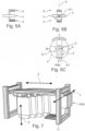
- the printing means 5 consist of at least two monochromatic 6 or bi-chromatic 7 mobile printing heads, in rotation and/or in translation, with at least one degree of freedom, said heads 6, 7 being able to be moved selectively , one by one, towards a determined spatial position PSD authorizing the printing of the surface 2′ of the part 2, this under the control of the calculation, management and control means 10, and in accordance with preprogrammed data, by example a printing program, also determining the displacement of the part 2 relative to the support structure 11 and to the determined spatial position PSD.
- the invention makes it possible to overcome the drawbacks associated with a multicolor printhead of large size along the stacking axis of the means 5, 8, 9 (axis Z in the figures) and whose nozzle lines of the same color are consistently spaced.
- the definition, for the different heads 6, 7 of the means 5, of a single spatial position PSD authorizing printing makes it possible to simplify and make more precise the kinematics of relative displacement and positioning of the different heads 6, 7 with respect to the part 2 in motion during the course of the printing.
- the printheads 6, 7 remain at least partially in the support structure 11 although they are movable relative to the latter.
- the printheads 6, 7 can be arranged side by side linearly along the third Y axis and be movable together in sliding along this Y axis, under the effect of a suitable translation actuator controlled by the calculation means 10 , management and control.
- the different monochrome heads 6 can be part of the same module forming multiple head 5 in the form of a bar, and be arranged in line in a horizontal direction (Y axis in the figures), therefore with a vertical size (Z axis in the figures ) minimum.
- the guiding of the block of heads 6 in translation can be done using a rail, a slide or the like forming part of the structure 11.
- the sensor 8 and drying 9 means are normally mounted fixed on said structure 11, but can also be provided to be mobile, like the print heads 6, to further increase the processing precision.
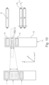
- THE figures 4A and 4B illustrate two successive operating steps of a process for printing a surface 2' using an installation 1 according to the figure 1 and comprising printing means 5 according to the figures 3A to 3C .
- the print head 6, 7 assigned to the color cyan is positioned by translation along the Y axis (horizontal direction) vertically and in the axis of the sensor means 8 and of the drying/cross-linking means 9 ( PSD position).
- the multi-axis robot arm 4 moves the part 2 in front of the said head 6, 7 which projects the cyan-colored ink onto the surface 2' to be printed according to a predefined printing program, executed by the calculation, management and control means 10 which also exploit the information provided by the sensor means 8 concerning the relative position and the displacement parameters of the part 2.
- the drying/crosslinking means 9 ensure the fixing and at least partial solidification of the deposited drops.
- the multiple head 5 in the form of a bar is then moved by one notch, by driving via a linear actuator (not shown), in such a way that the head 6, 7 assigned to the magenta color is found in the PSD position.
- the ink is projected according to a predefined program while the part 2 moves in front of the active head 6, 7 (magenta head) and the drops are dried by the means 9.
- the whole of the printing cycle can be repeated with a very slight voluntary shift of the printheads 6, 7 (compared to their position during the previous printing cycle), in order to obtain an even higher resolution. better.
- the printheads 6, 7 are arranged circularly around the second axis Z and are movable together in rotation around this axis Z, under the effect of a suitable rotary actuator (not shown) driven by means 10 of calculation, management and control.
- the printing process is carried out in successive stages by rotating the module grouping together the different heads 6 by a fraction of a turn (here a quarter turn) around the Z axis.
- the sensor and drying means 8 and 9 are normally fixed, but can be designed mobile concomitantly with the print heads 6.
- each of the print heads 6, 7 may also be movable individually, under the effect of a suitable controlled actuator (not shown) , specific to each head 6, 7 or common to all the heads 6, 7, sliding along the first axis X (not shown).
- the printheads 6, 7 can be arranged linearly side by side along the second axis Z and be, on the one hand, slidably movable together along this Z axis and, on the other hand, individually slidably movable along the first axis X, this under the effect of suitable translational actuators (not shown) controlled by the means 10 of calculation, management and control (for example an automaton), with which can be associated a console 10 'of control and programming.
- the control sequence of the printheads 6, 7 advantageously comprises, successively, first a sliding along the Z axis for the selection of the color to be applied, then a sliding along the X axis to bring the ejection orifice 13 (nozzle) concerned near the surface to be decorated.
- the printheads 6, 7 are mounted on or in the support structure 11 with the ability to move slidably, individually, along the three axes X, Y and Z, under the effect of adequate translational actuators controlled by the means 10 of calculation, management and control.
- the support structure 11 is provided with a cowling 12 with an opening 12' materializing the determined spatial position authorizing PSD printing, this opening 12' authorizing, if necessary, the passage of a print head 6 , 7.
- the support structure 11 with the cowling 12 advantageously has a columnar shape, simple and compact.
- the support structure 11 consists of a bay or a shelf for storing a printhead maintenance station 6, 7, and said installation 1 comprises a second displacement device 4' with at least five degrees of freedom, preferably a second six-axis robot arm, configured to selectively move a print head 6, 7 from its location in the bay or the storage shelf 11 to the determined spatial position PSD, and vice versa, this under the control of the means 10 calculation, management and control.
- Said printhead 6, 7 can be maintained at this position PSD during the progress of the printing or coating operation with this head 6, 7.
- the second robot arm 4′ is equipped, at its free end, with an automatic tool loader 14, with its automatic piloting device, on which can be mounted, temporarily and interchangeably, the head 6, 7 selected for the intended printing operation, the management of the operation of each print head 6, 7 and of the ink circulation, in line with the possible movements of the robot arm 4' carrier being carried out by the means 10.
- each printhead 6, 7 is, in this second embodiment of the installation, stored in the support structure 11 (whose size and number of reception slots is adapted to the needs in qualitative and quantitative terms).
- Each print head 6, 7 can be in ink recirculation or not, the management of the depressions is computerized (means 10) and adapts in real time to the movements of the robot 4 ', and to the orientations of the head 6, 7 concerned.
- each head 6, 7 on its automatic tool changer 14 allows any orientation of the mounted head to work in the entire sphere of action of the robot 4'.
- the robot 4' takes the head 6, 7 of the corresponding color from the storage rack 11 thanks to the automatic tool changer 14.
- the ink and printhead control parameters are advantageously adapted in real time to compensate for the movements of the wrist of the robot 4' when the head is set in motion at the end of the wrist of the robot.
- the different printheads 6, 7 all have similar constructions and external shapes.
- the installation 1 preferably comprises four monochromatic printing heads 6, each head 6 comprising at least two parallel rows of orifices 13 for ejecting ink of the same color (see in particular figures 8 and 9 ).
- each head 6 may alternatively comprise only one row of orifices 13 for a given color.
- the installation 1 can comprise two bi-chromatic printing heads 7, each head 7 being constituted by the assembly of two monochromatic heads 6 each comprising two rows of orifices 13 for ejecting ink of the same color.
- the installation 1 can exploit the instantaneous speeds of fractions of the surface 2' of the part 2 in displacement (acquired by the sensor means 8 and exploited by the means 10) to manage the printing cycle, as mentioned in the patent application French n° 18 54024 on behalf of the plaintiff, by way of illustrative example (cf. figure 2 notably).
- drying/or crosslinking means 9 can advantageously comprise a radiation source with means for adjusting the beam as described and represented in the patent application French n° 17 50260 on behalf of the plaintiff, by way of illustrative example.
Landscapes
- Engineering & Computer Science (AREA)
- Manufacturing & Machinery (AREA)
- Health & Medical Sciences (AREA)
- General Health & Medical Sciences (AREA)
- Toxicology (AREA)
- Ink Jet (AREA)
- Spray Control Apparatus (AREA)
- Coating Apparatus (AREA)
- Manipulator (AREA)
Claims (11)
- Anlage (1) zum Bedrucken und/oder Beschichten von Bauteilflächen, insbesondere von dreidimensionalen Flächen, wobei diese Anlage (1) hauptsächlich enthält:- einen Bauteilträger (3), der geeignet ist, ein zu dekorierendes oder zu beschichtendes Bauteil (2) zu empfangen und festzuhalten, und auf eine Verschiebevorrichtung (4) mit mindestens fünf Freiheitsgraden montiert ist, wie zum Beispiel ein sechsachsiger Roboterarm,- Tintenstrahldruckeinrichtungen (5) oder Ähnliches, die aus mindestens einem Druckkopf (6 oder 7) bestehen,- Sensoreinrichtungen (8), die geeignet sind, Positionierungs- und/oder Verschiebeparameter des Bauteils (2) zu messen, insbesondere Verschiebegeschwindigkeiten und/oder Positionierungskoordinaten,- ggf. Einrichtungen (9) zum Trocknen und/oder zur zumindest teilweisen Vernetzung der auf die Fläche (2') des zu dekorierenden Bauteils (2) gespritzten Substanzen,- Einrichtungen (10) zur Berechnung, Verwaltung und Steuerung, die geeignet und dazu bestimmt sind, die von den Sensoreinrichtungen (8) gelieferten Signale auszuwerten und mindestens die Druckeinrichtungen (7) und die Verschiebevorrichtung (4) zu steuern,wobei die Druckeinrichtungen (7), die Sensoreinrichtungen (8) und die möglichen Trockeneinrichtungen (9) nebeneinander, übereinandergelegt, auf einer ortsfesten Trägerstruktur (11) wie einem Sockel, einem Pfosten, einem Portalrahmen oder Ähnlichem angeordnet sind,wobei die Verschiebevorrichtung (4) und die Trägerstruktur (11) einander gegenüber angeordnet sind, und ein räumliches Bezugssystem (X,Y,Z) der ortsfesten Trägerstruktur (11) zugeordnet ist, wobei eine erste Achse (X) den Abstand zwischen der Verschiebevorrichtung (4) und der Trägerstruktur (11) bestimmt, eine zweite Achse (Z) der Stapelungsrichtung der Druck-, Sensor- und ggf. Trocknungseinrichtungen (5, 8, 9) entspricht, und eine dritte Achse (Y) lotrecht zu den zwei vorhergehenden Achsen (X und Z) ist,wobei die Druckeinrichtungen (5) aus mindestens zwei in Drehung und/oder Translationsverschiebung mit mindestens einem Freiheitsgrad beweglichen, monochromatischen (6) oder bichromatischen Druckköpfen (7) bestehen, wobei die Köpfe (6, 7) selektiv einzeln in eine bestimmte räumliche Position (PSD) verschoben werden können, die das Bedrucken der Fläche (2') des Bauteils (2) erlaubt, dies unter der Kontrolle der Rechen-, Verwaltungs- und Steuereinrichtungen (10), und in Übereinstimmung mit vorprogrammierten Daten, zum Beispiel einem Druckprogramm, die ebenfalls die Verschiebung des Bauteils (2) bezüglich der Trägerstruktur (11) und der bestimmten räumlichen Position (PSD) bestimmen.
- Anlage nach Anspruch 1, dadurch gekennzeichnet, dass die Druckköpfe (6, 7) nebeneinander linear gemäß der dritten Achse (Y) angeordnet und zusammen gemäß dieser Achse (Y) gleitend beweglich sind, dies unter der Wirkung eines geeigneten Translationsantriebs, der von den Rechen-, Verwaltungs- und Steuereinrichtungen (10) gesteuert wird.
- Anlage nach Anspruch 1, dadurch gekennzeichnet, dass die Druckköpfe (6, 7) kreisförmig um die zweite Achse (Z) herum angeordnet und zusammen in Drehung um diese Achse (Z) herum beweglich sind, dies unter der Wirkung eines geeigneten Drehantriebs, der von den Rechen-, Verwaltungs- und Steuereinrichtungen (10) gesteuert wird.
- Anlage nach einem der Ansprüche 2 und 3, dadurch gekennzeichnet, dass jeder der Druckköpfe (6, 7) unter der Wirkung eines geeigneten gesteuerten Antriebs, der jedem Kopf (6, 7) eigen oder allen Köpfen (6, 7) gemeinsam ist, in Gleitbewegung gemäß der ersten Achse (X) ebenfalls einzeln beweglich ist.
- Anlage nach Anspruch 1, dadurch gekennzeichnet, dass die Druckköpfe (6, 7) nebeneinander linear gemäß der zweiten Achse (Z) angeordnet sind, und einerseits gemäß dieser Achse (Z) zusammen gleitbeweglich und andererseits gemäß der ersten Achse (X) einzeln gleitbeweglich sind, dies unter der Wirkung von geeigneten Translationsantrieben, die von den Rechen-, Verwaltungs- und Steuereinrichtungen (10) gesteuert werden.
- Anlage nach Anspruch 1, dadurch gekennzeichnet, dass die Druckköpfe (6, 7) auf oder in die Trägerstruktur (11) mit einer Fähigkeit der Gleitverschiebung einzeln gemäß den drei Achsen (X, Y und Z) montiert sind, dies unter der Wirkung von geeigneten Translationsantrieben, die von den Rechen-, Verwaltungs- und Steuereinrichtungen (10) gesteuert werden.
- Anlage nach einem der Ansprüche 1 bis 6, dadurch gekennzeichnet, dass die Trägerstruktur (11) mit einer Verkleidung (12) mit einer Öffnung (12') versehen ist, die die den Druck erlaubende bestimmte räumliche Position (PSD) realisiert, wobei diese Öffnung (12') ggf. den Durchgang eines Druckkopfs (6, 7) erlaubt.
- Anlage nach Anspruch 1,dadurch gekennzeichnet, dass die Trägerstruktur (11) aus einem Lagergestell oder - regal einer Instandhaltungsstation der Druckköpfe (6, 7) besteht, und dass die Anlage (1) eine zweite Verschiebevorrichtung (4') mit mindestens fünf Freiheitsgraden enthält, vorzugsweise einen zweiten sechsachsigen Roboterarm, der konfiguriert ist, selektiv einen Druckkopf (6, 7) von seinem Standort im Lagergestell oder -regal (11) zur bestimmten räumlichen Position (PSD) und umgekehrt zu verschieben, dies unter der Kontrolle von Rechen-, Verwaltungs- und Steuereinrichtungen (10), wobei der Druckkopf (6, 7) während des Ablaufs des Druck- oder Beschichtungsvorgangs mit diesem Kopf (6, 7) in dieser Position (PSD) gehalten wird.
- Anlage nach Anspruch 8, dadurch gekennzeichnet, dass der zweite Roboterarm (4') im Bereich seines freien Endes mit einem automatischen Werkzeuglader (14) ausgerüstet ist, mit seiner automatischen Steuervorrichtung, auf den der für den vorgesehenen Druckvorgang ausgewählte Druckkopf (6, 7) vorübergehend und austauschbar montiert werden kann, wobei die Verwaltung des Betriebs jedes Druckkopfs (6, 7) und der Tintenzirkulation, in Übereinstimmung mit den möglichen Bewegungen des tragenden Roboterarms (4'), von den Einrichtungen (10) durchgeführt wird.
- Anlage nach einem der Ansprüche 1 bis 9, dadurch gekennzeichnet, dass sie vier monochromatische Druckköpfe (6) aufweist, wobei jeder Kopf (6) mindestens zwei parallele Reihen von Öffnungen (13) zum Ausstoß von Tinte gleicher Farbe aufweist.
- Anlage nach einem der Ansprüche 1 bis 9, dadurch gekennzeichnet, dass sie zwei bichromatische Druckköpfe (7) aufweist, wobei jeder Kopf (7) aus dem Zusammenbau von zwei monochromatischen Köpfen (6) besteht, die je zwei Reihen von Öffnungen (13) zum Ausstoß von Tinte gleicher Farbe aufweisen.
Applications Claiming Priority (2)
| Application Number | Priority Date | Filing Date | Title |
|---|---|---|---|
| FR1855490A FR3082780B1 (fr) | 2018-06-21 | 2018-06-21 | Installation d'impression ou de revetement de surfaces de pieces tridimensionnelles |
| PCT/EP2019/066241 WO2019243440A1 (fr) | 2018-06-21 | 2019-06-19 | Installation d'impression ou de revetement de surfaces de pieces tridimensionnelles |
Publications (2)
| Publication Number | Publication Date |
|---|---|
| EP3810429A1 EP3810429A1 (de) | 2021-04-28 |
| EP3810429B1 true EP3810429B1 (de) | 2023-08-09 |
Family
ID=62952166
Family Applications (1)
| Application Number | Title | Priority Date | Filing Date |
|---|---|---|---|
| EP19730822.4A Active EP3810429B1 (de) | 2018-06-21 | 2019-06-19 | Vorrichtung zum bedrucken oder beschichten von oberflächen dreidimensionaler teile |
Country Status (6)
| Country | Link |
|---|---|
| US (1) | US11794489B2 (de) |
| EP (1) | EP3810429B1 (de) |
| JP (1) | JP7451433B2 (de) |
| CN (1) | CN112492879B (de) |
| FR (1) | FR3082780B1 (de) |
| WO (1) | WO2019243440A1 (de) |
Families Citing this family (16)
| Publication number | Priority date | Publication date | Assignee | Title |
|---|---|---|---|---|
| US20210016454A1 (en) * | 2019-07-16 | 2021-01-21 | Kindred Systems Inc. | Control of modular end-of-arm tooling for robotic manipulators |
| JP7474946B2 (ja) * | 2019-12-04 | 2024-04-26 | パナソニックIpマネジメント株式会社 | 印刷装置 |
| US12337607B2 (en) | 2020-04-03 | 2025-06-24 | Norwalt Design, Inc. | Printing apparatus for printing directly onto containers |
| US11701905B2 (en) * | 2020-08-11 | 2023-07-18 | PS Business Services, LLC | Contoured surface printing |
| JP7651879B2 (ja) * | 2021-02-22 | 2025-03-27 | セイコーエプソン株式会社 | 立体物印刷装置 |
| JP7631878B2 (ja) * | 2021-02-22 | 2025-02-19 | セイコーエプソン株式会社 | 立体物印刷装置 |
| JP2022127795A (ja) * | 2021-02-22 | 2022-09-01 | セイコーエプソン株式会社 | 立体物印刷装置 |
| JP7195357B2 (ja) * | 2021-03-09 | 2022-12-23 | 本田技研工業株式会社 | インクジェット印刷方法及びインクジェット印刷装置 |
| JP7596865B2 (ja) * | 2021-03-09 | 2024-12-10 | セイコーエプソン株式会社 | 立体物印刷装置および立体物印刷方法 |
| JP7687016B2 (ja) * | 2021-03-25 | 2025-06-03 | セイコーエプソン株式会社 | 立体物印刷方法 |
| US12024907B2 (en) | 2021-09-15 | 2024-07-02 | ARC Ventures LLC | Articulated structural three-dimensional printing machine |
| FR3136399B1 (fr) | 2022-06-09 | 2024-09-06 | Saint Gobain | Dispositif d’impression sur verre, machine d’impression sur verre et procédé d’impression sur verre |
| US12485687B2 (en) * | 2022-12-15 | 2025-12-02 | The Boeing Company | Multi-printhead end effector and associated system and method |
| US12344010B2 (en) * | 2022-12-22 | 2025-07-01 | The Boeing Company | Multi-printhead end effector and associated system and method |
| JP2024138840A (ja) * | 2023-03-27 | 2024-10-09 | セイコーエプソン株式会社 | 立体物印刷装置 |
| FR3160126A1 (fr) | 2024-03-12 | 2025-09-19 | Smrc Automotive Holdings Netherlands B.V. | Pièce fonctionnelle et/ou décorative comprenant un motif visible par rétroéclairage et son procédé de fabrication |
Family Cites Families (25)
| Publication number | Priority date | Publication date | Assignee | Title |
|---|---|---|---|---|
| JPH05293955A (ja) * | 1992-04-17 | 1993-11-09 | Suzuki Sogyo Co Ltd | 曲面印刷方法 |
| US6578276B2 (en) * | 1998-01-27 | 2003-06-17 | Eastman Kodak Company | Apparatus and method for marking multiple colors on a contoured surface having a complex topography |
| EP0931649A3 (de) * | 1998-01-27 | 2000-04-26 | Eastman Kodak Company | Gerät und Verfahren zum Bedrucken einer profilierten Oberfläche mit komplexer Topologie |
| US6523921B2 (en) * | 2000-08-30 | 2003-02-25 | L&P Property Management | Method and apparatus for printing on rigid panels and other contoured or textured surfaces |
| JP2002084407A (ja) * | 2000-09-11 | 2002-03-22 | Minolta Co Ltd | データ生成装置及び立体表面記録装置 |
| GB2448690A (en) * | 2007-04-23 | 2008-10-29 | Seiko Epson Corp | Inkjet printing apparatus having a docking station |
| DE102007021765B4 (de) * | 2007-05-09 | 2010-06-17 | Bauer, Jörg R. | Vorrichtung zum gleichzeitigen Bedrucken einer Mehrzahl von gleichen Bauteilen mittels eines digitalen Druckverfahrens |
| EP2229282A1 (de) * | 2007-12-31 | 2010-09-22 | Exatec, LLC. | Vorrichtung und verfahren zum drucken dreidimensionaler artikel |
| JP5165527B2 (ja) | 2008-10-15 | 2013-03-21 | 株式会社ミマキエンジニアリング | 3次元プリンタおよびそれを用いた印刷方法 |
| FR2961127B1 (fr) * | 2010-06-11 | 2013-02-08 | Jean Pierre Rousselet | Machine d'impression sur objets de forme cylindrique |
| DE102012006370A1 (de) * | 2012-03-29 | 2013-10-02 | Heidelberger Druckmaschinen Aktiengesellschaft | System zum Bedrucken eines Objekts |
| US20130342592A1 (en) * | 2012-06-26 | 2013-12-26 | Apple Inc. | Inkjet printer for printing on a three-dimensional object and related apparatus and method |
| JP5781473B2 (ja) * | 2012-07-03 | 2015-09-24 | トリニティ工業株式会社 | 加飾部品の製造装置及び製造方法 |
| DE102012212469B4 (de) * | 2012-07-17 | 2022-10-06 | Peter Fornoff | Verfahren zum Bedrucken einer Oberfläche und Vorrichtung zum Bedrucken einer Oberfläche |
| JP6040755B2 (ja) * | 2012-12-19 | 2016-12-07 | 横浜ゴム株式会社 | 曲面印刷装置 |
| JP2015098103A (ja) * | 2013-11-18 | 2015-05-28 | 株式会社エルエーシー | インクジェットプリンタ |
| EP2873496A1 (de) * | 2013-11-18 | 2015-05-20 | ABB Technology AG | Drucksystem |
| DE102015203798A1 (de) * | 2014-03-27 | 2015-10-01 | Heidelberger Druckmaschinen Ag | Vorrichtung zum Bedrucken einer gekrümmten Oberfläche eines Objekts |
| JP2016016653A (ja) * | 2014-07-11 | 2016-02-01 | セイコーエプソン株式会社 | 記録装置 |
| JP5817010B1 (ja) | 2014-11-05 | 2015-11-18 | 二郎 工藤 | カラーインクジェットラベルプリンター |
| ES2915098T3 (es) * | 2015-02-02 | 2022-06-20 | Padaluma Ink Jet Solutions Gmbh | Impresora de inyección de tinta de una sola pasada |
| FR3033506B1 (fr) | 2015-03-11 | 2020-02-21 | Reydel Automotive B.V. | Procede et installation de revetement d'un corps avec formation d'une surface structuree |
| DE102015204532A1 (de) * | 2015-03-13 | 2016-09-15 | Heidelberger Druckmaschinen Ag | Vorrichtung zum Bedrucken einer Oberfläche eines Objekts |
| DE102016209649A1 (de) * | 2015-07-08 | 2017-01-12 | Heidelberger Druckmaschinen Aktiengesellschaft | Vorrichtung zum Bedrucken von mehrdimensionalen Objekten |
| FR3061676B1 (fr) * | 2017-01-12 | 2019-06-14 | Reydel Automotive B.V. | Installation d'impression et de sechage et procede d'impression et de sechage |
-
2018
- 2018-06-21 FR FR1855490A patent/FR3082780B1/fr active Active
-
2019
- 2019-06-19 CN CN201980041044.XA patent/CN112492879B/zh not_active Expired - Fee Related
- 2019-06-19 EP EP19730822.4A patent/EP3810429B1/de active Active
- 2019-06-19 JP JP2020571673A patent/JP7451433B2/ja active Active
- 2019-06-19 WO PCT/EP2019/066241 patent/WO2019243440A1/fr not_active Ceased
- 2019-06-19 US US17/252,622 patent/US11794489B2/en active Active
Also Published As
| Publication number | Publication date |
|---|---|
| CN112492879A (zh) | 2021-03-12 |
| WO2019243440A1 (fr) | 2019-12-26 |
| EP3810429A1 (de) | 2021-04-28 |
| FR3082780A1 (fr) | 2019-12-27 |
| BR112020026011A2 (pt) | 2021-03-23 |
| JP2021528287A (ja) | 2021-10-21 |
| CN112492879B (zh) | 2022-09-16 |
| FR3082780B1 (fr) | 2020-07-24 |
| US20210300061A1 (en) | 2021-09-30 |
| US11794489B2 (en) | 2023-10-24 |
| JP7451433B2 (ja) | 2024-03-18 |
Similar Documents
| Publication | Publication Date | Title |
|---|---|---|
| EP3810429B1 (de) | Vorrichtung zum bedrucken oder beschichten von oberflächen dreidimensionaler teile | |
| CN111032362B (zh) | 用于印刷曲面的方法以及用于印刷三维表面的装置 | |
| US8256890B2 (en) | Device for printing a component by means of a digital printing method | |
| US9149987B2 (en) | Device for producing three-dimensional models by a layering technique | |
| US7819055B2 (en) | Three-dimensional printer | |
| KR100906171B1 (ko) | 복수 세트의 프린트 헤드를 이용한 잉크젯 프린팅 방법 및장치 | |
| JP2006315400A (ja) | プレート状ワークの短辺部分に模様付けをする装置及び方法 | |
| JP4867754B2 (ja) | 三次元表面の印刷方法 | |
| TWI884179B (zh) | 印刷裝置 | |
| EP2839965B1 (de) | Verbesserte Tintenstrahl-Druckmaschine | |
| EP3995315A1 (de) | Verfahren und anlage zur aufbringung eines beschichtungsprodukts auf eine oberfläche | |
| EP3083212B1 (de) | Verfahren zum drucken einer dreidimensionalen lichtleitenden struktur | |
| US10981397B2 (en) | Machine for printing a plurality of objects | |
| EP3012109B1 (de) | Gesamtheit eines objekts mit griff und einer tintenstrahlmaschine zum bedrucken dieses objekts | |
| US12059696B2 (en) | System and method for actuating a treatment device | |
| US12202284B1 (en) | Printing machine comprising at least one print head | |
| RU2779266C2 (ru) | Установка для выполнения печати или для нанесения покрытия на поверхности трехмерных деталей | |
| JP2006289322A (ja) | 複合型インクジェットヘッド | |
| WO2024095576A1 (ja) | インクジェット記録装置 | |
| CN104228339A (zh) | 用于利用喷墨印刷头在对象的弯曲表面上印刷的设备 | |
| BR112020026011B1 (pt) | Instalação de impressão ou revestimento de superfícies de peças tridimensionais | |
| FR3025398A1 (fr) | Machine de report de composants electroniques sur cartes electroniques a plusieurs tetes de report | |
| FR2850642A1 (fr) | Dispositif de transfert d'objets industriels |
Legal Events
| Date | Code | Title | Description |
|---|---|---|---|
| STAA | Information on the status of an ep patent application or granted ep patent |
Free format text: STATUS: UNKNOWN |
|
| STAA | Information on the status of an ep patent application or granted ep patent |
Free format text: STATUS: THE INTERNATIONAL PUBLICATION HAS BEEN MADE |
|
| PUAI | Public reference made under article 153(3) epc to a published international application that has entered the european phase |
Free format text: ORIGINAL CODE: 0009012 |
|
| STAA | Information on the status of an ep patent application or granted ep patent |
Free format text: STATUS: REQUEST FOR EXAMINATION WAS MADE |
|
| 17P | Request for examination filed |
Effective date: 20210112 |
|
| AK | Designated contracting states |
Kind code of ref document: A1 Designated state(s): AL AT BE BG CH CY CZ DE DK EE ES FI FR GB GR HR HU IE IS IT LI LT LU LV MC MK MT NL NO PL PT RO RS SE SI SK SM TR |
|
| AX | Request for extension of the european patent |
Extension state: BA ME |
|
| DAV | Request for validation of the european patent (deleted) | ||
| DAX | Request for extension of the european patent (deleted) | ||
| GRAP | Despatch of communication of intention to grant a patent |
Free format text: ORIGINAL CODE: EPIDOSNIGR1 |
|
| STAA | Information on the status of an ep patent application or granted ep patent |
Free format text: STATUS: GRANT OF PATENT IS INTENDED |
|
| INTG | Intention to grant announced |
Effective date: 20230403 |
|
| GRAS | Grant fee paid |
Free format text: ORIGINAL CODE: EPIDOSNIGR3 |
|
| GRAA | (expected) grant |
Free format text: ORIGINAL CODE: 0009210 |
|
| STAA | Information on the status of an ep patent application or granted ep patent |
Free format text: STATUS: THE PATENT HAS BEEN GRANTED |
|
| P01 | Opt-out of the competence of the unified patent court (upc) registered |
Effective date: 20230621 |
|
| AK | Designated contracting states |
Kind code of ref document: B1 Designated state(s): AL AT BE BG CH CY CZ DE DK EE ES FI FR GB GR HR HU IE IS IT LI LT LU LV MC MK MT NL NO PL PT RO RS SE SI SK SM TR |
|
| REG | Reference to a national code |
Ref country code: GB Ref legal event code: FG4D Free format text: NOT ENGLISH |
|
| REG | Reference to a national code |
Ref country code: CH Ref legal event code: EP |
|
| REG | Reference to a national code |
Ref country code: IE Ref legal event code: FG4D Free format text: LANGUAGE OF EP DOCUMENT: FRENCH |
|
| REG | Reference to a national code |
Ref country code: DE Ref legal event code: R096 Ref document number: 602019034588 Country of ref document: DE |
|
| REG | Reference to a national code |
Ref country code: LT Ref legal event code: MG9D |
|
| REG | Reference to a national code |
Ref country code: NL Ref legal event code: MP Effective date: 20230809 |
|
| REG | Reference to a national code |
Ref country code: AT Ref legal event code: MK05 Ref document number: 1597068 Country of ref document: AT Kind code of ref document: T Effective date: 20230809 |
|
| PG25 | Lapsed in a contracting state [announced via postgrant information from national office to epo] |
Ref country code: GR Free format text: LAPSE BECAUSE OF FAILURE TO SUBMIT A TRANSLATION OF THE DESCRIPTION OR TO PAY THE FEE WITHIN THE PRESCRIBED TIME-LIMIT Effective date: 20231110 |
|
| PG25 | Lapsed in a contracting state [announced via postgrant information from national office to epo] |
Ref country code: IS Free format text: LAPSE BECAUSE OF FAILURE TO SUBMIT A TRANSLATION OF THE DESCRIPTION OR TO PAY THE FEE WITHIN THE PRESCRIBED TIME-LIMIT Effective date: 20231209 |
|
| PG25 | Lapsed in a contracting state [announced via postgrant information from national office to epo] |
Ref country code: SE Free format text: LAPSE BECAUSE OF FAILURE TO SUBMIT A TRANSLATION OF THE DESCRIPTION OR TO PAY THE FEE WITHIN THE PRESCRIBED TIME-LIMIT Effective date: 20230809 Ref country code: RS Free format text: LAPSE BECAUSE OF FAILURE TO SUBMIT A TRANSLATION OF THE DESCRIPTION OR TO PAY THE FEE WITHIN THE PRESCRIBED TIME-LIMIT Effective date: 20230809 Ref country code: PT Free format text: LAPSE BECAUSE OF FAILURE TO SUBMIT A TRANSLATION OF THE DESCRIPTION OR TO PAY THE FEE WITHIN THE PRESCRIBED TIME-LIMIT Effective date: 20231211 Ref country code: NO Free format text: LAPSE BECAUSE OF FAILURE TO SUBMIT A TRANSLATION OF THE DESCRIPTION OR TO PAY THE FEE WITHIN THE PRESCRIBED TIME-LIMIT Effective date: 20231109 Ref country code: NL Free format text: LAPSE BECAUSE OF FAILURE TO SUBMIT A TRANSLATION OF THE DESCRIPTION OR TO PAY THE FEE WITHIN THE PRESCRIBED TIME-LIMIT Effective date: 20230809 Ref country code: LV Free format text: LAPSE BECAUSE OF FAILURE TO SUBMIT A TRANSLATION OF THE DESCRIPTION OR TO PAY THE FEE WITHIN THE PRESCRIBED TIME-LIMIT Effective date: 20230809 Ref country code: LT Free format text: LAPSE BECAUSE OF FAILURE TO SUBMIT A TRANSLATION OF THE DESCRIPTION OR TO PAY THE FEE WITHIN THE PRESCRIBED TIME-LIMIT Effective date: 20230809 Ref country code: IS Free format text: LAPSE BECAUSE OF FAILURE TO SUBMIT A TRANSLATION OF THE DESCRIPTION OR TO PAY THE FEE WITHIN THE PRESCRIBED TIME-LIMIT Effective date: 20231209 Ref country code: HR Free format text: LAPSE BECAUSE OF FAILURE TO SUBMIT A TRANSLATION OF THE DESCRIPTION OR TO PAY THE FEE WITHIN THE PRESCRIBED TIME-LIMIT Effective date: 20230809 Ref country code: GR Free format text: LAPSE BECAUSE OF FAILURE TO SUBMIT A TRANSLATION OF THE DESCRIPTION OR TO PAY THE FEE WITHIN THE PRESCRIBED TIME-LIMIT Effective date: 20231110 Ref country code: FI Free format text: LAPSE BECAUSE OF FAILURE TO SUBMIT A TRANSLATION OF THE DESCRIPTION OR TO PAY THE FEE WITHIN THE PRESCRIBED TIME-LIMIT Effective date: 20230809 Ref country code: AT Free format text: LAPSE BECAUSE OF FAILURE TO SUBMIT A TRANSLATION OF THE DESCRIPTION OR TO PAY THE FEE WITHIN THE PRESCRIBED TIME-LIMIT Effective date: 20230809 |
|
| PG25 | Lapsed in a contracting state [announced via postgrant information from national office to epo] |
Ref country code: PL Free format text: LAPSE BECAUSE OF FAILURE TO SUBMIT A TRANSLATION OF THE DESCRIPTION OR TO PAY THE FEE WITHIN THE PRESCRIBED TIME-LIMIT Effective date: 20230809 |
|
| PG25 | Lapsed in a contracting state [announced via postgrant information from national office to epo] |
Ref country code: ES Free format text: LAPSE BECAUSE OF FAILURE TO SUBMIT A TRANSLATION OF THE DESCRIPTION OR TO PAY THE FEE WITHIN THE PRESCRIBED TIME-LIMIT Effective date: 20230809 |
|
| PG25 | Lapsed in a contracting state [announced via postgrant information from national office to epo] |
Ref country code: SM Free format text: LAPSE BECAUSE OF FAILURE TO SUBMIT A TRANSLATION OF THE DESCRIPTION OR TO PAY THE FEE WITHIN THE PRESCRIBED TIME-LIMIT Effective date: 20230809 Ref country code: RO Free format text: LAPSE BECAUSE OF FAILURE TO SUBMIT A TRANSLATION OF THE DESCRIPTION OR TO PAY THE FEE WITHIN THE PRESCRIBED TIME-LIMIT Effective date: 20230809 Ref country code: ES Free format text: LAPSE BECAUSE OF FAILURE TO SUBMIT A TRANSLATION OF THE DESCRIPTION OR TO PAY THE FEE WITHIN THE PRESCRIBED TIME-LIMIT Effective date: 20230809 Ref country code: EE Free format text: LAPSE BECAUSE OF FAILURE TO SUBMIT A TRANSLATION OF THE DESCRIPTION OR TO PAY THE FEE WITHIN THE PRESCRIBED TIME-LIMIT Effective date: 20230809 Ref country code: DK Free format text: LAPSE BECAUSE OF FAILURE TO SUBMIT A TRANSLATION OF THE DESCRIPTION OR TO PAY THE FEE WITHIN THE PRESCRIBED TIME-LIMIT Effective date: 20230809 Ref country code: CZ Free format text: LAPSE BECAUSE OF FAILURE TO SUBMIT A TRANSLATION OF THE DESCRIPTION OR TO PAY THE FEE WITHIN THE PRESCRIBED TIME-LIMIT Effective date: 20230809 Ref country code: SK Free format text: LAPSE BECAUSE OF FAILURE TO SUBMIT A TRANSLATION OF THE DESCRIPTION OR TO PAY THE FEE WITHIN THE PRESCRIBED TIME-LIMIT Effective date: 20230809 |
|
| REG | Reference to a national code |
Ref country code: DE Ref legal event code: R097 Ref document number: 602019034588 Country of ref document: DE |
|
| PLBE | No opposition filed within time limit |
Free format text: ORIGINAL CODE: 0009261 |
|
| STAA | Information on the status of an ep patent application or granted ep patent |
Free format text: STATUS: NO OPPOSITION FILED WITHIN TIME LIMIT |
|
| 26N | No opposition filed |
Effective date: 20240513 |
|
| PG25 | Lapsed in a contracting state [announced via postgrant information from national office to epo] |
Ref country code: SI Free format text: LAPSE BECAUSE OF FAILURE TO SUBMIT A TRANSLATION OF THE DESCRIPTION OR TO PAY THE FEE WITHIN THE PRESCRIBED TIME-LIMIT Effective date: 20230809 |
|
| PG25 | Lapsed in a contracting state [announced via postgrant information from national office to epo] |
Ref country code: BG Free format text: LAPSE BECAUSE OF FAILURE TO SUBMIT A TRANSLATION OF THE DESCRIPTION OR TO PAY THE FEE WITHIN THE PRESCRIBED TIME-LIMIT Effective date: 20230809 |
|
| PG25 | Lapsed in a contracting state [announced via postgrant information from national office to epo] |
Ref country code: BG Free format text: LAPSE BECAUSE OF FAILURE TO SUBMIT A TRANSLATION OF THE DESCRIPTION OR TO PAY THE FEE WITHIN THE PRESCRIBED TIME-LIMIT Effective date: 20230809 |
|
| PG25 | Lapsed in a contracting state [announced via postgrant information from national office to epo] |
Ref country code: MC Free format text: LAPSE BECAUSE OF FAILURE TO SUBMIT A TRANSLATION OF THE DESCRIPTION OR TO PAY THE FEE WITHIN THE PRESCRIBED TIME-LIMIT Effective date: 20230809 |
|
| REG | Reference to a national code |
Ref country code: CH Ref legal event code: PL |
|
| PG25 | Lapsed in a contracting state [announced via postgrant information from national office to epo] |
Ref country code: LU Free format text: LAPSE BECAUSE OF NON-PAYMENT OF DUE FEES Effective date: 20240619 |
|
| GBPC | Gb: european patent ceased through non-payment of renewal fee |
Effective date: 20240619 |
|
| PG25 | Lapsed in a contracting state [announced via postgrant information from national office to epo] |
Ref country code: IE Free format text: LAPSE BECAUSE OF NON-PAYMENT OF DUE FEES Effective date: 20240619 |
|
| PG25 | Lapsed in a contracting state [announced via postgrant information from national office to epo] |
Ref country code: BE Free format text: LAPSE BECAUSE OF NON-PAYMENT OF DUE FEES Effective date: 20240630 Ref country code: CH Free format text: LAPSE BECAUSE OF NON-PAYMENT OF DUE FEES Effective date: 20240630 |
|
| PG25 | Lapsed in a contracting state [announced via postgrant information from national office to epo] |
Ref country code: GB Free format text: LAPSE BECAUSE OF NON-PAYMENT OF DUE FEES Effective date: 20240619 |
|
| REG | Reference to a national code |
Ref country code: BE Ref legal event code: MM Effective date: 20240630 |
|
| PGFP | Annual fee paid to national office [announced via postgrant information from national office to epo] |
Ref country code: DE Payment date: 20250618 Year of fee payment: 7 |
|
| PGFP | Annual fee paid to national office [announced via postgrant information from national office to epo] |
Ref country code: FR Payment date: 20250618 Year of fee payment: 7 |
|
| PGFP | Annual fee paid to national office [announced via postgrant information from national office to epo] |
Ref country code: IT Payment date: 20250624 Year of fee payment: 7 |
|
| PG25 | Lapsed in a contracting state [announced via postgrant information from national office to epo] |
Ref country code: CY Free format text: LAPSE BECAUSE OF FAILURE TO SUBMIT A TRANSLATION OF THE DESCRIPTION OR TO PAY THE FEE WITHIN THE PRESCRIBED TIME-LIMIT; INVALID AB INITIO Effective date: 20190619 |
|
| PG25 | Lapsed in a contracting state [announced via postgrant information from national office to epo] |
Ref country code: HU Free format text: LAPSE BECAUSE OF FAILURE TO SUBMIT A TRANSLATION OF THE DESCRIPTION OR TO PAY THE FEE WITHIN THE PRESCRIBED TIME-LIMIT; INVALID AB INITIO Effective date: 20190619 |