EP3725419A1 - Applicateur de produit de revêtement, installation d'application comprenant un tel applicateur et procédé d'application au moyen d'un tel applicateur - Google Patents
Applicateur de produit de revêtement, installation d'application comprenant un tel applicateur et procédé d'application au moyen d'un tel applicateur Download PDFInfo
- Publication number
- EP3725419A1 EP3725419A1 EP20170084.6A EP20170084A EP3725419A1 EP 3725419 A1 EP3725419 A1 EP 3725419A1 EP 20170084 A EP20170084 A EP 20170084A EP 3725419 A1 EP3725419 A1 EP 3725419A1
- Authority
- EP
- European Patent Office
- Prior art keywords
- applicator
- nozzles
- faces
- face
- printing nozzles
- Prior art date
- Legal status (The legal status is an assumption and is not a legal conclusion. Google has not performed a legal analysis and makes no representation as to the accuracy of the status listed.)
- Granted
Links
Images




Classifications
-
- B—PERFORMING OPERATIONS; TRANSPORTING
- B05—SPRAYING OR ATOMISING IN GENERAL; APPLYING FLUENT MATERIALS TO SURFACES, IN GENERAL
- B05C—APPARATUS FOR APPLYING FLUENT MATERIALS TO SURFACES, IN GENERAL
- B05C5/00—Apparatus in which liquid or other fluent material is projected, poured or allowed to flow on to the surface of the work
- B05C5/02—Apparatus in which liquid or other fluent material is projected, poured or allowed to flow on to the surface of the work the liquid or other fluent material being discharged through an outlet orifice by pressure, e.g. from an outlet device in contact or almost in contact, with the work
- B05C5/0291—Apparatus in which liquid or other fluent material is projected, poured or allowed to flow on to the surface of the work the liquid or other fluent material being discharged through an outlet orifice by pressure, e.g. from an outlet device in contact or almost in contact, with the work the material being discharged on the work through discrete orifices as discrete droplets, beads or strips that coalesce on the work or are spread on the work so as to form a continuous coating
-
- B—PERFORMING OPERATIONS; TRANSPORTING
- B05—SPRAYING OR ATOMISING IN GENERAL; APPLYING FLUENT MATERIALS TO SURFACES, IN GENERAL
- B05B—SPRAYING APPARATUS; ATOMISING APPARATUS; NOZZLES
- B05B13/00—Machines or plants for applying liquids or other fluent materials to surfaces of objects or other work by spraying, not covered by groups B05B1/00 - B05B11/00
- B05B13/002—Machines or plants for applying coating liquids or other fluent materials by inkjet
-
- B—PERFORMING OPERATIONS; TRANSPORTING
- B05—SPRAYING OR ATOMISING IN GENERAL; APPLYING FLUENT MATERIALS TO SURFACES, IN GENERAL
- B05B—SPRAYING APPARATUS; ATOMISING APPARATUS; NOZZLES
- B05B13/00—Machines or plants for applying liquids or other fluent materials to surfaces of objects or other work by spraying, not covered by groups B05B1/00 - B05B11/00
- B05B13/02—Means for supporting work; Arrangement or mounting of spray heads; Adaptation or arrangement of means for feeding work
- B05B13/04—Means for supporting work; Arrangement or mounting of spray heads; Adaptation or arrangement of means for feeding work the spray heads being moved during spraying operation
- B05B13/0431—Means for supporting work; Arrangement or mounting of spray heads; Adaptation or arrangement of means for feeding work the spray heads being moved during spraying operation with spray heads moved by robots or articulated arms, e.g. for applying liquid or other fluent material to three-dimensional [3D] surfaces
-
- B—PERFORMING OPERATIONS; TRANSPORTING
- B05—SPRAYING OR ATOMISING IN GENERAL; APPLYING FLUENT MATERIALS TO SURFACES, IN GENERAL
- B05B—SPRAYING APPARATUS; ATOMISING APPARATUS; NOZZLES
- B05B13/00—Machines or plants for applying liquids or other fluent materials to surfaces of objects or other work by spraying, not covered by groups B05B1/00 - B05B11/00
- B05B13/02—Means for supporting work; Arrangement or mounting of spray heads; Adaptation or arrangement of means for feeding work
- B05B13/04—Means for supporting work; Arrangement or mounting of spray heads; Adaptation or arrangement of means for feeding work the spray heads being moved during spraying operation
- B05B13/0431—Means for supporting work; Arrangement or mounting of spray heads; Adaptation or arrangement of means for feeding work the spray heads being moved during spraying operation with spray heads moved by robots or articulated arms, e.g. for applying liquid or other fluent material to three-dimensional [3D] surfaces
- B05B13/0433—Means for supporting work; Arrangement or mounting of spray heads; Adaptation or arrangement of means for feeding work the spray heads being moved during spraying operation with spray heads moved by robots or articulated arms, e.g. for applying liquid or other fluent material to three-dimensional [3D] surfaces the work being vehicle components, e.g. vehicle bodies
-
- B—PERFORMING OPERATIONS; TRANSPORTING
- B05—SPRAYING OR ATOMISING IN GENERAL; APPLYING FLUENT MATERIALS TO SURFACES, IN GENERAL
- B05C—APPARATUS FOR APPLYING FLUENT MATERIALS TO SURFACES, IN GENERAL
- B05C5/00—Apparatus in which liquid or other fluent material is projected, poured or allowed to flow on to the surface of the work
- B05C5/02—Apparatus in which liquid or other fluent material is projected, poured or allowed to flow on to the surface of the work the liquid or other fluent material being discharged through an outlet orifice by pressure, e.g. from an outlet device in contact or almost in contact, with the work
- B05C5/027—Coating heads with several outlets, e.g. aligned transversally to the moving direction of a web to be coated
-
- B—PERFORMING OPERATIONS; TRANSPORTING
- B05—SPRAYING OR ATOMISING IN GENERAL; APPLYING FLUENT MATERIALS TO SURFACES, IN GENERAL
- B05D—PROCESSES FOR APPLYING FLUENT MATERIALS TO SURFACES, IN GENERAL
- B05D1/00—Processes for applying liquids or other fluent materials
- B05D1/02—Processes for applying liquids or other fluent materials performed by spraying
-
- B—PERFORMING OPERATIONS; TRANSPORTING
- B25—HAND TOOLS; PORTABLE POWER-DRIVEN TOOLS; MANIPULATORS
- B25J—MANIPULATORS; CHAMBERS PROVIDED WITH MANIPULATION DEVICES
- B25J11/00—Manipulators not otherwise provided for
- B25J11/0075—Manipulators for painting or coating
-
- B—PERFORMING OPERATIONS; TRANSPORTING
- B25—HAND TOOLS; PORTABLE POWER-DRIVEN TOOLS; MANIPULATORS
- B25J—MANIPULATORS; CHAMBERS PROVIDED WITH MANIPULATION DEVICES
- B25J15/00—Gripping heads and other end effectors
- B25J15/0019—End effectors other than grippers
-
- B—PERFORMING OPERATIONS; TRANSPORTING
- B41—PRINTING; LINING MACHINES; TYPEWRITERS; STAMPS
- B41J—TYPEWRITERS; SELECTIVE PRINTING MECHANISMS, i.e. MECHANISMS PRINTING OTHERWISE THAN FROM A FORME; CORRECTION OF TYPOGRAPHICAL ERRORS
- B41J2/00—Typewriters or selective printing mechanisms characterised by the printing or marking process for which they are designed
- B41J2/005—Typewriters or selective printing mechanisms characterised by the printing or marking process for which they are designed characterised by bringing liquid or particles selectively into contact with a printing material
- B41J2/01—Ink jet
- B41J2/135—Nozzles
- B41J2/14—Structure thereof only for on-demand ink jet heads
-
- B—PERFORMING OPERATIONS; TRANSPORTING
- B41—PRINTING; LINING MACHINES; TYPEWRITERS; STAMPS
- B41J—TYPEWRITERS; SELECTIVE PRINTING MECHANISMS, i.e. MECHANISMS PRINTING OTHERWISE THAN FROM A FORME; CORRECTION OF TYPOGRAPHICAL ERRORS
- B41J3/00—Typewriters or selective printing or marking mechanisms characterised by the purpose for which they are constructed
- B41J3/407—Typewriters or selective printing or marking mechanisms characterised by the purpose for which they are constructed for marking on special material
-
- B—PERFORMING OPERATIONS; TRANSPORTING
- B41—PRINTING; LINING MACHINES; TYPEWRITERS; STAMPS
- B41J—TYPEWRITERS; SELECTIVE PRINTING MECHANISMS, i.e. MECHANISMS PRINTING OTHERWISE THAN FROM A FORME; CORRECTION OF TYPOGRAPHICAL ERRORS
- B41J3/00—Typewriters or selective printing or marking mechanisms characterised by the purpose for which they are constructed
- B41J3/407—Typewriters or selective printing or marking mechanisms characterised by the purpose for which they are constructed for marking on special material
- B41J3/4073—Printing on three-dimensional objects not being in sheet or web form, e.g. spherical or cubic objects
-
- B—PERFORMING OPERATIONS; TRANSPORTING
- B05—SPRAYING OR ATOMISING IN GENERAL; APPLYING FLUENT MATERIALS TO SURFACES, IN GENERAL
- B05B—SPRAYING APPARATUS; ATOMISING APPARATUS; NOZZLES
- B05B1/00—Nozzles, spray heads or other outlets, with or without auxiliary devices such as valves, heating means
- B05B1/02—Nozzles, spray heads or other outlets, with or without auxiliary devices such as valves, heating means designed to produce a jet, spray, or other discharge of particular shape or nature, e.g. in single drops, or having an outlet of particular shape
- B05B1/08—Nozzles, spray heads or other outlets, with or without auxiliary devices such as valves, heating means designed to produce a jet, spray, or other discharge of particular shape or nature, e.g. in single drops, or having an outlet of particular shape of pulsating nature, e.g. delivering liquid in successive separate quantities
- B05B1/083—Nozzles, spray heads or other outlets, with or without auxiliary devices such as valves, heating means designed to produce a jet, spray, or other discharge of particular shape or nature, e.g. in single drops, or having an outlet of particular shape of pulsating nature, e.g. delivering liquid in successive separate quantities the pulsating mechanism comprising movable parts
-
- B—PERFORMING OPERATIONS; TRANSPORTING
- B05—SPRAYING OR ATOMISING IN GENERAL; APPLYING FLUENT MATERIALS TO SURFACES, IN GENERAL
- B05B—SPRAYING APPARATUS; ATOMISING APPARATUS; NOZZLES
- B05B12/00—Arrangements for controlling delivery; Arrangements for controlling the spray area
- B05B12/02—Arrangements for controlling delivery; Arrangements for controlling the spray area for controlling time, or sequence, of delivery
- B05B12/04—Arrangements for controlling delivery; Arrangements for controlling the spray area for controlling time, or sequence, of delivery for sequential operation or multiple outlets
-
- B—PERFORMING OPERATIONS; TRANSPORTING
- B05—SPRAYING OR ATOMISING IN GENERAL; APPLYING FLUENT MATERIALS TO SURFACES, IN GENERAL
- B05B—SPRAYING APPARATUS; ATOMISING APPARATUS; NOZZLES
- B05B12/00—Arrangements for controlling delivery; Arrangements for controlling the spray area
- B05B12/16—Arrangements for controlling delivery; Arrangements for controlling the spray area for controlling the spray area
- B05B12/18—Arrangements for controlling delivery; Arrangements for controlling the spray area for controlling the spray area using fluids, e.g. gas streams
-
- B—PERFORMING OPERATIONS; TRANSPORTING
- B05—SPRAYING OR ATOMISING IN GENERAL; APPLYING FLUENT MATERIALS TO SURFACES, IN GENERAL
- B05B—SPRAYING APPARATUS; ATOMISING APPARATUS; NOZZLES
- B05B13/00—Machines or plants for applying liquids or other fluent materials to surfaces of objects or other work by spraying, not covered by groups B05B1/00 - B05B11/00
- B05B13/02—Means for supporting work; Arrangement or mounting of spray heads; Adaptation or arrangement of means for feeding work
- B05B13/04—Means for supporting work; Arrangement or mounting of spray heads; Adaptation or arrangement of means for feeding work the spray heads being moved during spraying operation
- B05B13/0447—Installation or apparatus for applying liquid or other fluent material to conveyed separate articles
- B05B13/0452—Installation or apparatus for applying liquid or other fluent material to conveyed separate articles the objects being vehicle components, e.g. vehicle bodies
-
- B—PERFORMING OPERATIONS; TRANSPORTING
- B05—SPRAYING OR ATOMISING IN GENERAL; APPLYING FLUENT MATERIALS TO SURFACES, IN GENERAL
- B05B—SPRAYING APPARATUS; ATOMISING APPARATUS; NOZZLES
- B05B15/00—Details of spraying plant or spraying apparatus not otherwise provided for; Accessories
- B05B15/60—Arrangements for mounting, supporting or holding spraying apparatus
- B05B15/65—Mounting arrangements for fluid connection of the spraying apparatus or its outlets to flow conduits
-
- B—PERFORMING OPERATIONS; TRANSPORTING
- B05—SPRAYING OR ATOMISING IN GENERAL; APPLYING FLUENT MATERIALS TO SURFACES, IN GENERAL
- B05B—SPRAYING APPARATUS; ATOMISING APPARATUS; NOZZLES
- B05B7/00—Spraying apparatus for discharge of liquids or other fluent materials from two or more sources, e.g. of liquid and air, of powder and gas
- B05B7/02—Spray pistols; Apparatus for discharge
- B05B7/04—Spray pistols; Apparatus for discharge with arrangements for mixing liquids or other fluent materials before discharge
- B05B7/0408—Spray pistols; Apparatus for discharge with arrangements for mixing liquids or other fluent materials before discharge with arrangements for mixing two or more liquids
-
- B—PERFORMING OPERATIONS; TRANSPORTING
- B41—PRINTING; LINING MACHINES; TYPEWRITERS; STAMPS
- B41J—TYPEWRITERS; SELECTIVE PRINTING MECHANISMS, i.e. MECHANISMS PRINTING OTHERWISE THAN FROM A FORME; CORRECTION OF TYPOGRAPHICAL ERRORS
- B41J2/00—Typewriters or selective printing mechanisms characterised by the printing or marking process for which they are designed
- B41J2/005—Typewriters or selective printing mechanisms characterised by the printing or marking process for which they are designed characterised by bringing liquid or particles selectively into contact with a printing material
- B41J2/01—Ink jet
- B41J2/135—Nozzles
- B41J2/14—Structure thereof only for on-demand ink jet heads
- B41J2002/14475—Structure thereof only for on-demand ink jet heads characterised by nozzle shapes or number of orifices per chamber
-
- B—PERFORMING OPERATIONS; TRANSPORTING
- B62—LAND VEHICLES FOR TRAVELLING OTHERWISE THAN ON RAILS
- B62D—MOTOR VEHICLES; TRAILERS
- B62D65/00—Designing, manufacturing, e.g. assembling, facilitating disassembly, or structurally modifying motor vehicles or trailers, not otherwise provided for
Definitions
- the present invention relates to a coating product applicator which comprises one of the printing nozzles each comprising an outlet channel opening downstream through a coating product ejection orifice.
- print heads comprising printing nozzles
- two print heads can be mounted side-by-side and hinged to each other to follow the geometry of a surface to be coated.
- a strip of paint applied to a bodywork has sharp edges along the axis of movement of the applicator but not at its ends.
- the start line of the application which corresponds to the activation zone of the printing nozzles
- the finish line of the paint strip which corresponds to the stopping or deactivation of these nozzles, are serrated, that is to say they have irregularities. It would be possible to envisage using the nozzles of another applicator to create a line transverse to a first application pass, with a slight overlap, in order to smooth the phenomenon of serration as much as possible.
- the coating station in which the application of a strip is implemented is in "tracking" mode, that is to say that the conveyor moving the motor vehicle bodies does not stop during the application, the robot can access the front part of the vehicle and then, after a lapse of time, the rear part.
- This operating mode is not really compatible with the precise application of paint, insofar as it is desired to produce precisely defined strips along the conveyor axis.
- the position of the vehicle over time is not defined precisely enough to create completely clear start and finish lines.
- the speed of the conveyor is not known very precisely, in particular because of the undulations due to the regulation and to the movement of the driving motor of the conveyor.
- the multi-axis robot supporting the applicator must be fitted with a seventh robotic axis, in practice constituted by a rail for moving the robot along the axis of movement of the conveyor.
- This solution is also not precise enough with regard to the expected result. It is also expensive in terms of cycle time, because it requires positioning the robot on the front windshield area, before painting, then repositioning the robot on the rear windshield area, also before painting.
- the present invention aims to solve these problems by providing a novel coating product applicator which allows both precise application of coating product, including at the start and finish lines of a web or a strip. Another reason, while having a cycle time reduced compared to known solutions.
- the invention relates to a coating product applicator comprising printing nozzles each comprising an outlet channel opening downstream through a coating product ejection orifice.
- the printing nozzles are distributed over at least two faces of a body of the applicator and the ejection orifices of these nozzles extend along at least two non-parallel planes.
- the printing nozzles arranged on one face of the body of the applicator can be used for certain phases of application of coating product, for example parallel to the largest dimension of a strip of paint to apply to the roof of the body of a motor vehicle, while the printing nozzles distributed over a second face of the same ejection nozzle applicator can be used to achieve the start and finish lines of such tape, with great precision.
- the invention relates to an installation for applying a coating product to objects to be coated, which comprises at least one applicator as mentioned above, preferably mounted on the arm of a multiaxis robot intended for move it relative to the objects to be coated.
- This process makes it possible to apply a coating product with great precision and quickly.
- the application distance between the ejection orifices of the active printing nozzles and the surface of an object being coated is between 5 and 50 mm .
- Installation I shown in figures 1 , 4 and 5 is provided for the application of paint on objects O which, in the example of the figures, are motor vehicle bodies. More precisely, in this example, the installation I aims to allow the creation of a band B of contrasting color, for example black, on the roof of such a bodywork.
- the objects to be coated may be parts of motor vehicle bodies, for example bumpers or, more generally, any object that can be coated, for example a part of an aircraft cabin or a body of a household appliance. , these examples not being limiting.
- the installation I comprises a conveyor 2 designed to move the objects O along a conveying axis X2 perpendicular to the plane of the figure 1 and parallel to the plans of figures 4 and 5 .
- the installation I also comprises an applicator 10 mounted at the end of the arm 22 of a multiaxis robot 20 placed in the vicinity of the conveyor 2.
- the applicator 10 comprises several nozzles 12 which are identical to each other and which each belong to a print head 13.
- the applicator 10 comprises a body 14 which supports the nozzles 12 and which constitutes a rigid structural element allowing the nozzles 12 to be positioned in space.
- the body 14 is in one piece.
- the body 14 is parallelepiped 14 and defines a front face 142, a rear face 143 parallel to the front face 142, two longitudinal faces 144 and 145 parallel to each other and two transverse faces 146 and 147 parallel to each other.
- the front and rear faces 142 and 143 are perpendicular to the longitudinal faces 144 and 145, on the one hand, and to the transverse faces 146 and 147 on the other hand.
- the longitudinal faces 144 and 145 are, moreover, perpendicular to the transverse faces 146 and 147.
- the faces 144 to 147 are adjacent to the face 142.
- the front face 142 of the body 14 is turned towards an object to be coated when the applicator 10 works, to make the main part of a pattern, by applying a coating product to an object O.
- the nozzles 12 are rigidly mounted on the body 14. More precisely, four rows of sixteen nozzles 12 are arranged on the front face 142 of the body 14, these nozzles projecting from this front face which is flat.
- each nozzle 12 belongs to a printing head 13 which further comprises a control member 132, for example of the piezoelectric component type, and a rod 134.
- Each nozzle 12 comprises a needle 122 controlled by the control member 132 from printhead 13 to which the nozzle belongs to. Needle 122 is connected to component 132 by rod 134.
- the paint to be applied flows into a channel 16 formed in the body 14 and circulates, from one nozzle 12 to the other, in the direction of the arrows F2.
- the channel 16 constitutes a common means of supplying various nozzles 12 located on the face 142 of the applicator 10.
- 121 is the part of a nozzle 12 which projects from a face of the body 14. Inside the part 121 of a nozzle, a seat 124 is provided against which the needle 122 of the nozzle selectively comes. in support, being controlled by component 132.
- An outlet channel 126 is formed in each nozzle 12, downstream of its needle 122 and of its seat 124. This outlet channel opens outwardly, opposite the needle 122, through an ejection orifice 127 formed in a front face 128 of the nozzle 12, more precisely in the front face 128 of its part 121.
- each nozzle 12 constitutes a printing nozzle intended to selectively eject paint through its ejection orifice 127.
- the diameter of the outlet channel 126 of a nozzle 126 and d127 is denoted by d126 the diameter of the ejection orifice 127 of this nozzle.
- d126 the diameter of the ejection orifice 127 of this nozzle.
- the diameter d127 is between 50 micrometers ( ⁇ m) and 500 ⁇ m, preferably between 100 and 200 ⁇ m, more preferably of the order of 150 ⁇ m.
- each nozzle 12 is capable of discharging from its ejection orifice 127, a succession of droplets G.
- these droplets G are shown as all leaving the printing nozzles 12 at the same time, which does not correspond to the method described below but makes it possible to identify the flow paths of these nozzles.
- ⁇ 142 the main plane of the front face 142 which is plane.
- ⁇ 127 the plane in which are arranged the ejection orifices 127 of the nozzles 12 arranged on the front face 142.
- the planes ⁇ 142 and ⁇ 127 are parallel and the orifices 127 are themselves distributed on the front face 142, in the vicinity of this one.
- the transverse surface 147 is equipped with four nozzles 12 identical to those mounted on the front face 142, which constitute a row of printing nozzles and which also protrude from this surface 147, which is flat and of which we denote ⁇ 147 the main shot.
- the ejection orifices 127 of the nozzles 12 mounted on the surface 147 extend in a plane ⁇ '127 parallel to the plane ⁇ 147 and can be considered to be equally distributed on the surface 147, in the vicinity thereof.
- ⁇ 146 the transverse surface 146 which is flat and of which the main plane is denoted ⁇ 146.
- the ejection orifices of these nozzles 12 extend in a plane ⁇ "127 parallel to the plane ⁇ 146. These orifices can be considered to be equally distributed over the surface 146, in the vicinity thereof.
- the planes ⁇ 142 and ⁇ 147, on the one hand, ⁇ 142 and ⁇ 146, on the other hand, are not parallel to each other.
- the outlet orifices 127 of the nozzles respectively provided on the faces 142, 146 and 147 extend in at least two non-parallel dimensions.
- the applicator 10 can be qualified as a multi-nozzle-multi-dimension (MBMD) head. It constitutes a coating product applicator which enables such a product to be applied with a high degree of precision, as is apparent from the following explanations.
- MBMD multi-nozzle-multi-dimension
- ⁇ a defined angle, inside the body 14, 10 between the planes ⁇ 142 and ⁇ 147.
- this angle ⁇ is equal to 90 °.
- this angle ⁇ may be between 30 ° and 150 °, preferably between 60 and 90 °. Preferred values of this angle are 60 °, 90 ° and 120 °.
- the angle ⁇ is also the angle between the planes ⁇ 127 and ⁇ '127, measured on the side of these planes facing the body 14.
- the nozzles arranged 12 on the faces 142 and 147 which respectively eject paint perpendicular to the planes ⁇ 127 and ⁇ '127, make it possible to eject paint in two directions not parallel.
- the situation is the same for the printing nozzles 12 respectively located on the faces 142 and 146.
- the applicator 10 When it is appropriate to create a strip B by forming patterns on the roof of a motor vehicle body O, the applicator 10 is brought by the multi-axis robot 20 above the area of the roof to be coated, then the applicator 10 is moved parallel to the longitudinal axis of the body, which is in practice parallel to the axis X2, as represented by arrows F4 and F4 'at the figure 4 .
- the nozzles 12 arranged on the front face 142 of the body 14 are activated.
- the needles 122 of these nozzles 12 are moved away from their seats 124 by the actuators 132 and the rods 134 of the printing heads 13. corresponding.
- the outlet channels 126 of these nozzles are supplied with paint and paint is ejected through their respective ejection orifices 127, which are in the plane ⁇ 127, in the direction of the roof of the body O, as represented by the droplets G which flow in the direction of arrows F42 at the figure 4 .
- This printing technique makes it possible to constitute, on the roof of the vehicle, a strip B, the longitudinal edges of which, parallel to the direction of movement of the applicator according to the arrows F4 and F4 ', are well defined and rectilinear.
- a first step consists in making the band B by moving the applicator 10 in the direction of the arrows F4 and F4 'at the figure 4 , while supplying the nozzles 12, the ejection orifices 127 of which are located in the plane ⁇ 127.
- the robot 20 brings the transverse face 147 of the applicator 10 facing the rear edge of the roof of the body and moves this applicator 10 perpendicular to the axis X2, in the arrows F5 and F5 'at the figure 5 , while activating the nozzles 12 mounted on this transverse face 147, which has the effect of discharging droplets G of paint towards the edge of the roof from the ejection orifices 127 of these nozzles located in the plane ⁇ '127 , in the direction of arrow F52 at the figure 5 .
- This makes it possible to constitute, at the rear end of the strip B, a clean transverse border without indentations.
- An operation of the same type is then carried out, in the same second step of the method, at the level of the front edge of the border B, by activating the four nozzles 12 arranged on the transverse face 146 of the body 14, which eject paint through. their ejection orifices 127 located in the plane ⁇ "127.
- the order of implementation of the sub-steps of the second step, consisting of creating the front and rear transverse borders of the strip B, can be reversed.
- the production of a transverse border can be carried out only at the front or only at the rear of the strip B.
- the application distance that is to say the distance measured between the ejection orifices 127 of the active printing nozzles 12 and the surface of the roof of the object O being coating, is advantageously between 5 and 50 mm. This makes it possible to increase the paint transfer rate and to reduce the distance of the overspray, that is to say of the diffuse paint cloud, compared to the imprint of the main spray, that is to say -to say of the cloud of paint directed to the principal on the bodywork. This ensures that the uncontrolled drops G of paint are deposited as close as possible to the coverage area of the main spray, and therefore drops under control, intended to constitute the B band.
- the nozzles 12 are completely integrated inside the body 14 of the applicator 10.
- the front surfaces 128 of the nozzles 12, in which the ejection orifices 127 are formed are afferent with the lateral faces of the body 14, in particular the front 142 and transverse 147 faces shown in figure 6 .
- the planes ⁇ 142 and ⁇ 127 are the same, as are the planes ⁇ 147 and ⁇ '127.
- the planes ⁇ 142 and ⁇ 147 are not parallel, as are the planes ⁇ 127, ⁇ '127.
- the nozzles 12 respectively arranged on the surfaces 142 and 147 make it possible to eject paint in two non-parallel directions.
- the angle ⁇ defined as in the first embodiment is equal to 120 °.
- the printing nozzles 12 arranged on the face 142 are identical to each other and the printing nozzles 12 arranged on the face 147 are identical to each other, but the diameter d127 of the ejection orifices 127 of the nozzles printing 12 disposed on the surface 142 have a first value, while the diameter of 127 of the orifices 127 of the nozzles 12 disposed on the surface 147 has a second value, less than the first value.
- the ejection orifices 127 of the nozzles 12 disposed on the transverse face 147 are thinner than the ejection holes 127 of the nozzles 12 disposed on the front face 142.
- the printing nozzles 12 arranged on the different faces of the body 14 are used at different times during the implementation of a coating product application process. This is why provision is made for the printing nozzles, the ejection orifices of which are distributed over two distinct faces of the body 14, to be activated independently of one another, when the applicator 10 is in operation.
- a common paint circulation channel or channels 16 is provided to supply the nozzles 12 mounted on the surface 142, while another comparable channel is provided to supply the nozzles. 12 provided on the face 146 and that yet another comparable channel is provided to supply the nozzles 12 provided on the face 147.
- the supply of paint to these different channels is regulated by valves, preferably integrated into the body 14, controlled. independently of each other.
- the different actuators 132 of the print heads 13 including the different nozzles 12 can be controlled independently of each other.
- a decorative hood strip can be made with a width of 100mm over a length of 1m, which corresponds to an area of 0.1m 2 , while coating an entire roof amounts to covering an area of approximately 2mx2m, i.e. 4m 2 .
- Applicator 10 could therefore be selected depending on the intended use.
- the applicator 10 can be equipped with an interface 18 provided on its rear face 143 and allowing its rapid assembly / disassembly at the end of the arm 22 of the robot 20.
- This interface enables a connection to be made. fluidic and electrical of the applicator 10 with the robot 20.
- the interface 10 can operate with a magnetic clipping system or by any other suitable method.
- each applicator 10 is designed to apply paint with a flow rate belonging to a range of flow rates, therefore designed to coat a surface area included in a range of areas, during the time allocated to implement the method of the invention. . this allows the robot 20 to load the applicator 10 best suited to the pattern to be produced on the vehicle body entering its work zone.
- the applicator 10 is described in the case where printing nozzles 12 are provided on three faces of the body 14, namely the faces 142, 146 and 147.
- the nozzles 12 can be provided on only two of these faces or, on the contrary, on four, five or six of these faces, it being specified here that, preferably, the rear face 143 is not equipped with nozzles 12.
- the invention is described above in the case of the application of paint to a motor vehicle body. It is particularly suitable for the application of paint of the "base coat" type, that is to say a layer of color with or without an effect, as well as for the application of mono or two-component varnishes.
- the application of a primer is also possible.
- the applicator 10 can be used to apply ink or any other coating material.
- a static mixer is integrated into the installation I, more precisely inside the body 14, on the path of the channel 16 , just upstream of nozzles 12.
- an additional guide air can be brought to the level of the front face 128 of each nozzle 12 in order to contain the drops G coming out of the ejection orifices 127.
- This additional guide air can be ejected. in the form of an air gap, i.e. an air curtain acting as a border that cannot be crossed by the droplets G, an air ring or several air jets shaped with a vortex shape, converging or diverging in the direction of the axis of the outlet channel 126 of each nozzle.
- This additional guide air can be brought to the vicinity of nozzles 12 individually or for a group of nozzles, for example, a row of nozzles, a column of nozzles or a matrix of nozzles, or even in a grouped fashion for all the nozzles arranged. on one face of the body 14 the applicator 10.
- a system for electrostatic charging of the applied coating product can be provided, this system being internally charged and / or externally charged, which makes it possible to accelerate the drops G emerging from the ejection orifices 127 and deposit them on the surface to be coated which is connected to ground.
- Such an electrostatic system can be provided individually for each nozzle 12, for a group of nozzles, for example per row, per column or for a matrix of nozzles or under. the form of a single electrostatic system provided for all the nozzles of the applicator 10.
- nozzles 12 indicated above and shown in the figures are indicative. Alternatively, they can be different.
- several printing nozzles 12 are provided on a first face of the body 14, for example the face 142, to be used during the first step of the process. These nozzles are preferably arranged in rows and columns.
- One or more nozzles are provided on another face, for example face 146 or 147, for the second step.
- the number of nozzles provided on the first face of the body 14 is different, in practice greater than the number of nozzles provided on the other face.
- the body 14 of the applicator 10 can be supported by a device other than a multi-axis robot, provided that this device makes it possible to implement the two steps of the method of the invention.
- a cross table can be used for an application on parallelepipedic objects
- the installation I comprises several applicators 10.
- the body 14 may have a shape other than a parallelepiped.
- the body 14 can be formed of several parts assembled in a rigid manner, that is to say without the possibility of relative movement between them.
- the main planes ⁇ 142, ⁇ 146 and ⁇ 147 are defined as mean planes of these faces, as are the planes ⁇ 127, ⁇ '127 and ⁇ "127. This is particularly the case if the applicator is used to apply a paint or a varnish to door frames or contours, which may have a section having several sides connected by shelves which can be painted at the same time.
- the invention is described above during its implementation for the creation of a strip. However, it is applicable for the creation of other patterns on any object to be coated.
Landscapes
- Engineering & Computer Science (AREA)
- Robotics (AREA)
- Mechanical Engineering (AREA)
- Manufacturing & Machinery (AREA)
- Coating Apparatus (AREA)
- Application Of Or Painting With Fluid Materials (AREA)
- Spray Control Apparatus (AREA)
Abstract
Description
- La présente invention concerne un applicateur de produit de revêtement qui comprend un des buses d'impression comportant chacune un canal de sortie débouchant vers l'aval par un orifice d'éjection de produit de revêtement.
- La demande de customisation de la décoration apposée sur des objets tend à augmenter sensiblement. Par exemple, le revêtement de carrosseries de véhicule automobile bi-ton devient de plus en plus fréquent. Ainsi, de nombreux véhicules automobiles présentent des montants de porte de couleur noire, alors que le reste de la carrosserie est peint avec une autre couleur. Pour des véhicules haut de gamme, du noir de style est appliqué sur les montants de porte, sur des surfaces délimitées par des caches. Une autre technique consiste à poser, à la main, des autocollants noirs sur les montants. Ces deux modes de réalisation de montants de couleur noire sont consommateurs de temps, exigent une main d'œuvre qualifiée et sont onéreux. Des problèmes analogues se posent lors de la réalisation d'un motif décoratif sur une carrosserie, par exemple une bande de couleur noire sur le toit ou le capot de la carrosserie, voire un toit complet de couleur différente du reste de la carrosserie.
- L'application de peinture au moyen de têtes d'impression comprenant des buses d'impression permet d'atteindre une certaine précision d'application de peinture. Comme envisagé dans
EP-A-1884365 , deux têtes d'impression peuvent être montées côte-à-côte et articulées l'une par rapport à l'autre pour suivre la géométrie d'une surface à revêtir. - Toutefois, malgré l'utilisation d'un système goutte à goutte, d'un robot multiaxe précis déplaçant la tête d'impression et d'un automate rapide, avec un temps de scrutation de l'ordre de la milliseconde (ms), une bande de peinture appliquée sur une carrosserie présente des bords nets selon l'axe de déplacement de l'applicateur mais pas à ses extrémités. La ligne de départ de l'application, qui correspond à la zone d'activation des buses d'impression, et la ligne d'arrivée de la bande de peinture, qui correspond à l'arrêt ou à la désactivation de ces buses, sont dentelées, c'est-à-dire qu'elles présentent des irrégularités. On pourrait envisager d'utiliser les buses d'un autre applicateur pour créer une ligne transversale à une première passe d'application, avec un léger recouvrement, afin de lisser au maximum le phénomène de dentelure. Toutefois, dans ce cas, il se pose un problème d'accessibilité du robot à la zone d'application. Par exemple, si l'on considère une bande réalisée sur le toit de la carrosserie d'un véhicule automobile, un robot doit pouvoir atteindre la zone de pare-brise avant et la zone de pare-brise arrière pour appliquer une ligne transversale, selon la largeur du véhicule. En pratique, ceci est très difficile à mettre en œuvre.
- Si la station de revêtement dans laquelle est mise en œuvre l'application d'une bande est en mode « tracking », c'est-à-dire que le convoyeur déplaçant les carrosseries de véhicule automobile ne s'arrête pas lors de l'application, le robot peut accéder à la partie avant du véhicule puis, après un laps de temps, à la partie arrière. Ce mode de fonctionnement n'est pas réellement compatible avec l'application précise de peinture, dans la mesure où l'on souhaite réaliser des bandes précisément définies selon l'axe convoyeur. De plus, la position du véhicule au cours du temps n'est pas définie de façon suffisamment précise pour créer des lignes de départ et d'arrivée totalement nettes. Dans ce cas, la vitesse du convoyeur n'est pas connue de façon très précise, en particulier à cause des ondulations dues à la régulation et au mouvement du moteur d'entrainement du convoyeur.
- Si la station est en mode « stop and go », c'est-à-dire que la carrosserie est immobilisée dans une position donnée lors de l'application de peinture, le robot multiaxe supportant l'applicateur doit être équipé d'un septième axe robotique, en pratique constitué par un rail de déplacement du robot le long de l'axe de déplacement du convoyeur. Cette solution n'est également pas assez précise au regard du résultat escompté. Elle est également couteuse en termes de temps de cycle, car elle nécessite de positionner le robot sur la zone de pare-brise avant, avant de peindre, puis de repositionner le robot sur la zone de pare-brise arrière, également avant de peindre.
- Une telle problématique se pose également pour l'application de peinture bi-ton sur des éléments autres que de carrosseries de véhicule automobile complètes, notamment sur des pièces en matériau synthétique, telles que les pare-chocs, ou dans le domaine aéronautique, pour le revêtement des carlingues d'aéronefs.
- La présente invention vise à résoudre ces problèmes en proposant un nouvel applicateur de produit de revêtement qui permet à la fois une application précise de produit de revêtement, y compris au niveau des lignes de départ et d'arrivée d'une bande ou d'un autre motif, tout en présentant un temps de cycle réduit par rapport aux solutions connues.
- A cet effet, l'invention concerne un applicateur de produit de revêtement comprenant des buses d'impression comportant chacune un canal de sortie débouchant vers l'aval par un orifice d'éjection de produit de revêtement. Conformément à l'invention, les buses d'impression sont réparties sur au moins deux faces d'un corps de l'applicateur et les orifices d'éjection de de ces buses s'étendent selon au moins deux plans non parallèles.
- Grâce à l'invention, les buses d'impression disposées sur une face du corps de l'applicateur peuvent être utilisées pour certaines phases d'application de produit de revêtement, par exemple parallèlement à la plus grande dimension d'une bande de peinture à appliquer sur le toit de la carrosserie d'un véhicule automobile, alors que les buses d'impression réparties sur une deuxième face du même applicateur de buses d'éjection peuvent être utilisées pour réaliser les lignes de départ et d'arrivée d'une telle bande, avec une grande précision.
- Selon les aspects, avantageux mais non obligatoires de l'invention, un tel applicateur peut incorporer une ou plusieurs caractéristiques suivantes prises selon toute combinaison technique admissible :
- Les deux plans forment, entre eux et du côté du corps de l'applicateur, un angle compris entre 30° et 150°, de préférence entre 60° et 120°, de préférence égal à 60°, 90° ou 120°.
- L'applicateur comprend plusieurs premières buses d'impression, dont les orifices d'éjection sont répartis sur une première face du corps, et au moins une deuxième buse d'impression, dont l'orifice de sortie est sur une deuxième face du corps et en ce que le nombre de premières buses est différent du nombre de deuxième(s) buse(s).
- Les buses d'impression sont réparties sur les deux faces du corps sont du même type et ont des orifices d'éjection de dimensions identiques.
- Les buses d'impression réparties sur les deux faces du corps sont de même type et ont, sur chaque face, des orifices d'éjection de dimensions identiques et, entre deux faces, des orifices d'éjection de dimensions différentes.
- Les deux faces du corps sur lesquelles sont réparties les buses d'impression sont adjacentes.
- Les buses d'impression réparties sur deux faces distinctes du corps sont activées indépendamment les unes des autres lorsque l'applicateur est en fonctionnement.
- L'applicateur comprend un mélangeur intégré dans le corps de l'applicateur, en amont des buses d'impression.
- Selon un autre aspect, l'invention concerne une installation d'application de produit de revêtement sur des objets à revêtir, qui comprend au moins un applicateur tel que mentionné ci-dessus, de préférence monté sur le bras d'un robot multiaxe prévu pour le déplacer par rapport aux objets à revêtir.
- Selon un autre aspect, l'invention concerne un procédé d'application de produit de revêtement sur un objet à revêtir, au moyen d'un applicateur tel que mentionné ci-dessus, ce procédé comprenant au moins les étapes suivantes consistant à :
- a) réaliser un motif avec le produit de revêtement, en déplaçant l'applicateur selon un premier axe de déplacement, alors que des premières buses d'impression réparties sur une première face du corps de l'applicateur, sont actives; et
- b) réaliser au moins une bordure transversale du motif, en déplaçant l'applicateur selon un deuxième axe perpendiculaire au premier axe, alors que des deuxièmes buses d'impression réparties sur une deuxième face du corps, sont actives.
- Ce procédé permet d'appliquer un produit de revêtement avec une grande précision et de façon rapide.
- De préférence, lors des étapes a) et/ou b) la distance d'application entre, les orifices d'éjection des buses d'impression actives et la surface d'un objet en cours de revêtement, est comprise entre 5 et 50 mm.
- L'invention sera mieux comprise et d'autres avantages de celle-ci seront mieux compris à la lumière de la description qui va suivre de deux modes de réalisation d'un applicateur, d'une installation et d'un procédé conformes à l'invention, donnés uniquement à titre d'exemple et faite en référence aux dessins annexés dans lesquels :
- [
Fig 1 ] Lafigure 1 est une représentation schématique de principe, en vue de face, d'une installation conforme à l'invention incorporant un applicateur conforme à l'invention ; - [
Fig 2 ] Lafigure 2 est une vue en perspective de l'applicateur de l'installation de lafigure 1 ; - [
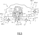
Fig 3 ] Lafigure 3 est une vue en élévation avec arrachement partiel du détail III à lafigure 2 ; - [
Fig 4 ] Lafigure 4 est une vue de côté de l'installation de lafigure 1 , lors d'une première étape d'un procédé d'application de produit de revêtement conforme à l'invention ; - [
Fig 5 ] Lafigure 5 est une vue analogue à lafigure 4 , lors d'une deuxième étape du même procédé ; et - [
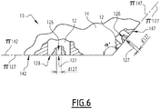
Fig 6 ] Lafigure 6 est une vue en élévation, avec arrachement partiel, d'une partie d'un applicateur conforme à un deuxième mode de réalisation de l'invention. - L'installation I représentée aux
figures 1 ,4 et5 est prévue pour l'application de peinture sur des objets O qui, dans l'exemple des figures, sont des carrosseries de véhicule automobile. Plus précisément, dans cet exemple, l'installation I vise à permettre la création d'une bande B de couleur contrastée, par exemple noire, sur le toit d'une telle carrosserie. - En variante, les objets à revêtir peuvent être des parties de carrosseries de véhicule automobile, par exemple des pare-chocs ou, plus généralement, tout objet pouvant être revêtu, par exemple une partie de carlingue d'aéronef ou une caisse d'appareil électroménager, ces exemples n'étant pas limitatifs.
- L'installation I comprend un convoyeur 2 prévu pour déplacer les objets O le long d'un axe de convoyage X2 perpendiculaire au plan de la
figure 1 et parallèle aux plans desfigures 4 et5 . - L'installation I comprend également un applicateur 10 monté à l'extrémité du bras 22 d'un robot multiaxe 20 disposé au voisinage du convoyeur 2.
- L'applicateur 10 comprend plusieurs buses 12 qui sont identiques entre elles et qui appartiennent chacune à une tête d'impression 13.
- L'applicateur 10 comprend un corps 14 qui supporte les buses 12 et qui constitue un élément structurel rigide permettant de positionner les buses 12 dans l'espace. De préférence, le corps 14 est monobloc. Dans l'exemple, le corps 14 est parallélépipédique 14 et définit une face avant 142, une face arrière 143 parallèle à la face avant 142, deux faces longitudinales 144 et 145 parallèles entre elles et deux faces transversales 146 et 147 parallèles entre elles. Les faces avant et arrière 142 et 143 sont perpendiculaires aux faces longitudinales 144 et 145, d'une part, et aux faces transversales 146 et 147 d'autre part. Les faces longitudinales 144 et 145 sont, par ailleurs, perpendiculaires aux faces transversales 146 et 147. Les faces 144 à 147 sont adjacentes à la face 142. La face avant 142 du corps 14 est tournée vers un objet à revêtir lorsque l'applicateur 10 fonctionne, pour réaliser la partie principale d'un motif, en appliquant un produit de revêtement sur un objet O.
- Les buses 12 sont montées de façon rigide sur le corps 14. Plus précisément, quatre rangés de seize buses 12 sont disposées sur la face avant 142 du corps 14, ces buses étant en saillie de cette face avant qui est plane.
- Comme il ressort de la
figure 3 , chaque buse 12 appartient à une tête d'impression 13 qui comprend, en outre, un organe de commande 132, par exemple de type composant piézoélectrique, et une tige 134. Chaque buse 12 comprend un pointeau 122 piloté par l'organe de commande 132 de la tête d'impression 13 à laquelle appartient la buse. Le pointeau 122 est relié au composant 132 par la tige 134. - La peinture à appliquer s'écoule dans un canal 16 ménagé dans le corps 14 et circule, d'une buse 12 à l'autre, dans le sens des flèches F2. Le canal 16 constitue un moyen d'alimentation commun de différentes buses 12 situées sur la face 142 de l'applicateur 10.
- On note 121 la partie d'une buse 12 qui est en saillie d'une face du corps 14. A l'intérieur de la partie 121 d'une buse, un siège 124 est ménagé contre lequel le pointeau 122 de la buse vient sélectivement en appui, en étant commandé par le composant 132.
- Un canal de sortie 126 est ménagé dans chaque buse 12, en aval de son pointeau 122 et de son siège 124. Ce canal de sortie débouche vers l'extérieur, à l'opposé du pointeau 122, par un orifice d'éjection 127 ménagé dans une face frontale 128 de la buse 12, plus précisément dans la face frontale 128 de sa partie 121.
- Ainsi, chaque buse 12 constitue une buse d'impression destinée à éjecter sélectivement de la peinture par son orifice d'éjection 127.
- On note d126 le diamètre du canal de sortie 126 d'une buse 126 et d127 le diamètre de l'orifice d'éjection 127 de cette buse. Par exemple, les diamètres d26 et d 27 sont égaux. Le diamètre d127 est compris entre 50 micromètres (µm) et 500 µm, de préférence entre 100 et 200 µm, de préférence encore de l'ordre de 150 µm.
- Ainsi, chaque buse 12 est capable de décharger à partir de son orifice d'éjection 127, une succession de gouttelettes G. A la
figure 2 , ces gouttelettes G sont représentées comme sortant toutes en même temps des buses d'impression 12, ce qui ne correspond pas au procédé décrit ci-après mais permet de repérer les trajets d'écoulement de ces buses. - On note, π142 le plan principal de la face avant 142 qui est plane. On note π127 le plan dans lequel sont disposés les orifices d'éjection 127 des buses 12 disposées sur la face avant 142. Les plans π142 et π127 sont parallèles et les orifices 127 sont eux-mêmes répartis sur la face avant 142, au voisinage de celle-ci.
- La surface transversale 147 est équipée de quatre buses 12 identiques à celles montées sur la face avant 142, qui constituent une rangée de buses d'impression et qui font également saillie par rapport à cette surface 147, laquelle est plane et dont on note π147 le plan principal.
- Les orifices d'éjection 127 des buses 12 montées sur la surface 147 s'étendent dans un plan π'127 parallèle au plan π147 et peuvent être considérés comme également répartis sur la surface 147, au voisinage de celle-ci.
- De la même façon, quatre buses d'impression 12 sont montées sur la surface transversale 146 qui est plane et dont on note π146 le plan principal. Les orifices d'éjection de ces buses 12 s'étendent dans un plan π"127 parallèle au plan π146. Ces orifices peuvent être considérés comme également répartis sur la surface 146, au voisinage de celle-ci
- Les plans π142 et π147, d'une part, π142 et π146, d'autre part, ne sont pas parallèles entre eux. Ainsi, les orifices de sortie 127 des buses respectivement prévues sur les faces 142, 146 et 147 s étendent dans au moins deux dimensions non parallèles.
- En ce sens, l'applicateur 10 peut être qualifié de tête multi-buses-multi-dimensions (MBMD). Il constitue un applicateur de produit de revêtement qui permet d'appliquer un tel produit avec un haut degré de précision, ainsi qu'il ressort des explications qui suivent.
- On note α un angle défini, à l'intérieur du corps 14, 10 entre les plans π142 et π147.
- Dans l'exemple des
figures 1 à 5 , cet angle α vaut 90°. - En pratique, cet angle α peut être compris entre 30° et 150 °, de préférence entre 60 et 90°. Des valeurs préférentielles de cet angle sont 60°, 90° et 120 °.
- Comme les plans π127 et π'127 sont respectivement parallèles aux plans π142 et π147, l'angle α est également l'angle entre les plans π127 et π'127, mesuré du côté de ces plans tournés vers le corps 14.
- Dans la mesure où l'angle α ne vaut pas 180°, les buses disposées 12 sur les faces 142 et 147, qui éjectent respectivement de la peinture perpendiculairement aux plans π127 et π'127, permettent d'éjecter de la peinture dans deux direction non parallèles.
- La situation est la même pour les buses d'impression 12 respectivement situées sur les faces 142 et 146.
- Lorsqu'il convient de créer une bande B en formant des motifs sur le toit d'une carrosserie O de véhicule automobile, l'applicateur 10 est amené par le robot multiaxe 20 au-dessus de la zone du toit à revêtir, puis l'applicateur 10 est déplacé parallèlement à l'axe longitudinal de la carrosserie, qui est en pratique parallèle à l'axe X2, comme représenté par les flèches F4 et F4' à la
figure 4 . - Lors de ces déplacements, les buses 12 disposées sur la face avant 142 du corps 14 sont activées.
- En d'autres termes, les pointeaux 122 de ces buses 12 sont écartés de leurs sièges 124 par les actionneurs 132 et les tiges 134 des têtes d'impression 13 correspondantes. Les canaux de sorties 126 de ces buses sont alimentés en peinture et de la peinture est éjectée par leurs orifices d'éjection respectifs 127, qui sont dans le plan π127, en direction du toit de la carrosserie O, comme représenté par les gouttelettes G qui s'écoulent dans le sens des flèches F42 à la
figure 4 . Cette technique d'impression permet de constituer, sur le toit du véhicule, une bande B dont les bords longitudinaux, parallèles au sens de déplacement de l'applicateur selon les flèches F4 et F4', sont bien définis et rectilignes. - Ainsi, dans un procédé d'application de peinture sur un objet O tel que la carrosserie représentée aux
figures 1 ,4 et5 , une première étape consiste à réaliser la bande B en déplaçant l'applicateur 10 dans le sens des flèches F4 et F4' à lafigure 4 , tout en alimentant les buses 12 dont les orifices d'éjection 127 sont situés dans le plan π127. - Ensuite, pour réaliser les bordures transversales de la bande B et dans une deuxième étape, le robot 20 amène la face transversale 147 de l'applicateur 10 en regard du bord arrière du toit de la carrosserie et déplace cet applicateur 10 perpendiculairement à l'axe X2, dans le des flèches F5 et F5' à la
figure 5 , tout en activant les buses 12 montées sur cette face transversale 147, ce qui a pour effet de décharger des gouttelettes G de peinture en direction du bord du toit à partir des orifices d'éjection 127 de ces buses situés dans le plan π'127, dans le sens de la flèche F52 à lafigure 5 . Ceci permet de constituer, à l'extrémité arrière de la bande B une bordure transversale nette et sans dentelure. - Le passage de l'applicateur 10 de la position de la
figure 4 à celle de lafigure 5 est rapide et facile à mettre en œuvre par le robot multiaxe 20, notamment car les faces 142 et 147 sont adjacentes. - Une opération du même type est ensuite effectuée, dans la même deuxième étape du procédé, au niveau du bord avant de la bordure B, en activant les quatre buses 12 disposées sur la face transversale 146 du corps 14, qui éjectent de la peinture à travers leurs orifices d'éjection 127 situés dans le plan π"127.
- En variante, l'ordre de mise en œuvre des sous-étapes de la deuxième étape, consistant à créer les bordures transversales avant et arrière de la bande B, peut être inversé.
- Selon une autre variante, la réalisation d'une bordure transversale peut être effectuée seulement à l'avant ou seulement à l'arrière de la bande B.
- Au cours du procédé d'application de la peinture représenté aux
figures 4 et5 , la distance d'application, c'est-à-dire la distance mesurée entre les orifices d'éjection 127 des buses d'impression 12 actives et la surface du toit de l'objet O en cours de revêtement, est avantageusement comprise entre 5 et 50 mm. Ceci permet d'augmenter le taux de transfert de peinture et de réduire l'éloignement de l'overspray, c'est-à-dire du nuage de peinture diffus, par rapport à l'empreinte du spray principal, c'est-à-dire du nuage de peinture dirigé au principal sur la carrosserie. Ceci permet d'assurer que les gouttes G de peinture non contrôlées se déposent au plus près possible de la zone de couverture du spray principal, donc des gouttes sous contrôle, destinées à constituer la bande B. - Dans le deuxième mode de réalisation de l'invention représenté à la
figure 6 , les éléments analogues à ceux du premier mode de réalisation portent les mêmes références. Dans ce qui suit, on ne décrit que ce qui distingue ce mode de réalisation du précédent. - Dans ce mode de réalisation, les buses 12 sont complètement intégrées à l'intérieur du corps 14 de l'applicateur 10. En d'autres termes, les surfaces frontales 128 des buses 12, dans lesquelles sont ménagés les orifices d'éjection 127, sont afférentes avec les faces latérales du corps 14, notamment les faces frontales 142 et transversale 147 représentées à la
figure 6 . En d'autres termes, les plans π142 et π127 sont confondus, de même que les plans π147 et π'127. - Comme précédemment, les plans π142 et π147 ne sont pas parallèles, de même que les plans π127, π'127. Ainsi, les buses 12 respectivement disposées sur les surfaces 142 et 147 permettent d'éjecter de la peinture dans deux direction non parallèles.
- Ici, l'angle α défini comme dans le premier mode de réalisation vaut 120°.
- Dans ce mode de réalisation, les buses d'impression 12 disposées sur la face 142 sont identiques entre elles et les buses d'impression 12 disposées sur la face 147 sont identiques entre elles, mais le diamètre d127 des orifices d'éjection 127 des buses d'impression 12 disposées sur la surface 142 présentent une première valeur, alors que le diamètre d'127 des orifices 127 des buses 12 disposées sur la surface 147 présente une deuxième valeur, inférieure à la première valeur. En d'autres termes, des orifices d'éjection 127 des buses 12 disposées sur la face transversale 147 sont plus fins que les orifices d'éjection 127 des buses 12 disposées sur la face frontale 142. Ceci peut être rapproché du fait que, lorsque les buses 12 qui équipent la face 142 sont utilisées, on réalise une surface d'aire relativement importante, pour laquelle un débit de peinture relativement important est nécessaire, comme cela ressort des explications relatives à la première étape du procédé mentionné ci-dessus. Au contraire, lorsqu'on réalise une bordure transversale de la bande B dans le cadre de la deuxième étape du procédé, une précision plus importante est nécessaire, et la surface à revêtir est d'aire inférieure. En effet, plus le diamètre d127 ou d'127 est petit, plus les gouttelettes sortant de l'orifice d'éjection 127 sont petites et plus de la netteté du bord réalisé est franche.
- On comprend que les buses d'impression 12 disposées sur les différentes faces du corps 14 sont utilisées à des moments différents lors de la mise en œuvre d'un procédé d'application de produit de revêtement. C'est pourquoi, il est prévu que les buses d'impression dont les orifices d'éjection sont répartis sur deux faces distinctes du corps 14 sont activées indépendamment les unes des autres, lorsque l'applicateur 10 est en fonction. Par exemple, il est possible de prévoir qu'un canal ou des canaux de circulation de peinture commun(s) 16 soit prévu pour alimenter les buses 12 montées sur la surface 142, alors qu'un autre canal comparable est prévu pour alimenter les buses 12 prévues sur la face 146 et qu'encore un autre canal comparable est prévu pour alimenter les buses 12 prévues sur la face 147. L'alimentation en peinture de ces différents canaux est régulée par des vannes, de préférence intégrées au corps 14, pilotées indépendamment les unes des autres.
- En outre, les différents actionneurs 132 des têtes d'impression 13 incluant les différents buses 12 peuvent être pilotés indépendamment les uns des autres.
- Sur une ligne de peinturage de carrosseries de véhicule automobile, selon les modèles de carrosserie et les motifs à réaliser, on peut être amené à revêtir des surfaces d'aire très différentes avec un applicateur du type de l'applicateur 10. Par exemple, une bande décorative de capot peut être réalisée avec une largeur de 100mm sur une longueur de 1m, ce qui correspond à une aire de 0,1m2, alors que revêtir un toit entier revient à recouvrir une surface d'environ 2mx2m, soit 4m2. L'applicateur 10 pourrait dont être sélectionné en fonction de l'utilisation prévue.
- Pour ce faire, on peut prévoir que l'applicateur 10 est équipé d'une interface 18 prévue sur sa face arrière 143 et permettant son montage/démontage rapide à l'extrémité du bras 22 du robot 20. Cette interface permet de réaliser une connexion fluidique et électrique de l'applicateur 10 avec le robot 20. Par exemple, l'interface 10 peut fonctionner avec un système de clipsage magnétique ou selon toute autre méthode appropriée.
- Dans ce cas, différents applicateurs 10 sont stockés dans un magasin, dans la zone d'activité du robot 20, par exemple au pied de celui-ci. Chaque applicateur est prévu pour appliquer de la peinture avec un débit appartenant à une gamme de débits, donc prévu pour revêtir une surface d'aire comprise dans une gamme d'aires, pendant le temps alloué pour mettre en œuvre le procédé de l'invention. Ceci permet au robot 20 de charger l'applicateur 10 le plus adapté au motif à réaliser sur la carrosserie de véhicule entrant dans sa zone de travail.
- Dans la description ci-dessus, l'applicateur 10 est décrit dans le cas où des buses d'impression 12 sont prévues sur trois faces du corps 14, à savoir les faces 142, 146 et 147. En variante, les buses 12 peuvent être prévues sur seulement deux de ces faces ou, au contraire, sur quatre, cinq ou six de ces faces, étant précisé ici que, de préférence, la face arrière 143 n'est pas équipée de buses 12.
- L'invention est décrite ci-dessus dans le cas de l'application de peinture sur une carrosserie de véhicule automobile. Elle est particulièrement adaptée à l'application de peinture de type « base coat », c'est-à-dire une couche de couleur avec ou sans effet, ainsi qu'à l'application de vernis mono ou bi-composant. L'application d'un apprêt est également envisageable.
- En variante, l'applicateur 10 peut être utilisé pour appliquer une encre ou tout autre produit de revêtement.
- Lorsque le produit appliqué est bi- ou multi-composants, et selon une variante non représentée de l'invention, un mélangeur statique est intégré à l'installation I, plus précisément à l'intérieur du corps 14, sur le trajet du canal 16, juste en amont des buses 12.
- Selon un aspect optionnel de l'invention, un air de guidage additionnel peut être amené au niveau de la face frontale 128 de chaque buse 12 afin de contenir les gouttes G sortant des orifices d'éjection 127. Cet air de guidage additionnel peut être éjecté sous la forme d'une lame d'air, c'est à dire d'un rideau d'air agissant comme une frontière que ne peuvent pas franchir les gouttelettes G, d'un anneau d'air ou de plusieurs jets d'air conformés avec une forme en vortex, convergente ou divergente en direction de l'axe du canal de sortie 126 de chaque buse. Cet air de guidage additionnel peut être amené au voisinage de buses 12 de façon individualisée ou pour un groupe de buses, par exemple, une ligne de buses, une colonne de buses ou une matrice de buses, voire de façon groupée pour toutes les buses disposées sur une face de du corps 14 l'applicateur 10.
- Pour améliorer, le rendement du dépôt de l'application obtenue avec l'applicateur 10, un système de charge électrostatique du produit de revêtement appliqué peut être prévu, ce système étant à charge interne et/ou à charge externe, ce qui permet d'accélérer les gouttes G sortant des orifices d'éjection 127 et de les déposer sur la surface à revêtir qui est reliée à la masse. Un tel système électrostatique peut être prévu individuellement pour chaque buse 12, pour un groupe de buses, par exemple par ligne, par colonne ou pour une matrice de buses ou sous la forme d'un unique système électrostatique prévu pour toutes les buses de l'applicateur 10.
- Les nombres de buses 12 mentionnés indiqués ci-dessus et montrés sur les figures sont indicatifs. En variante, ils peuvent être différents. De préférence, plusieurs buses d'impression 12 sont prévues sur une première face du corps 14, par exemple la face 142, pour être utilisées au cours de la première étape du procédé. Ces buses sont, de préférence disposées en rangées et en colonnes. Une ou plusieurs buses sont prévues sur une autre face, par exemple la face 146 ou 147, pour la deuxième étape. Le nombre de buses prévues sur la première face du corps 14 est différent, en pratique supérieur, au nombre de buses prévues sur l'autre face.
- En variante, le corps 14 de l'applicateur 10 peut être supporté par un dispositif autre qu'un robot multiaxe, pour autant que ce dispositif permet de mettre en œuvre les deux étapes du procédé de l'invention. Par exemple, une table croisée peut être utilisée pour une application sur des objets parallélépipédiques
- En variante, l'installation I comprend plusieurs applicateurs 10.
- En variante, le corps 14 peut avoir une forme autre que parallélépipédique.
- Selon une autre variante, le corps 14 peut être formé de plusieurs parties assemblées de façon rigide, c'est-à-dire sans possibilité de mouvement relatif entre elles.
- Si les faces du corps 14 sur lesquelles sont montées les buses d'impression 12 ne sont pas planes, les plans principaux π142, π146 et π147 sont définis comme des plans moyens de ces faces, de même que les plans π127, π'127 et π"127. Tel est notamment le cas si l'applicateur est utilisé pour appliquer une peinture ou un vernis sur des encadrements ou contours de porte, qui peuvent avoir une section présentant plusieurs côtés reliés par des rayons qui peuvent être peints en même temps.
- L'invention est décrite ci-dessus lors de sa mise en œuvre pour la création d'une bande. Elle est toutefois applicable pour la création d'autres motifs sur tout objet à revêtir.
- Les modes de réalisation et variantes envisagés ci-dessus peuvent être combinés pour générer de nouveaux modes de réalisation de l'invention.
Claims (11)
- Applicateur (10) de produit de revêtement comprenant des buses d'impression (12) comportant chacune un canal de sortie (126) débouchant vers l'aval par un orifice (127) d'éjection de produit de revêtement, caractérisé en ce que les buses d'impression (12) sont réparties sur au moins deux faces (142, 146, 147) d'un corps (14) de l'applicateur (10) et les orifices d'éjection (127) de de ces buses s'étendent selon au moins deux plans non parallèles (π127, π'127, π"127).
- Applicateur selon la revendication 1, caractérisé en ce que les deux plans (π127, π'127, π"127) forment, entre eux et du côté du corps (14) de l'applicateur (10), un angle (α) compris entre 30° et 150°, de préférence entre 60° et 120°, de préférence égal à 60°, 90° ou 120°.
- Applicateur selon l'une des revendications précédentes, caractérisé en ce qu'il comprend plusieurs premières buses d'impression (12), dont les orifices d'éjection (127) sont répartis sur une première face (142) du corps (14), et au moins une deuxième buse d'impression (12), dont l'orifice de sortie (127) est sur une deuxième face (146, 147) du corps, et en ce que le nombre de premières buses est différent du nombre de deuxième(s) buse(s).
- Applicateur selon l'une des revendications précédentes, caractérisé en ce que les buses d'impression (12) réparties sur les deux faces (142, 146, 147) du corps sont du même type et ont des orifices d'éjection de dimensions identiques (d127).
- Applicateur selon l'une des revendications 1 à 3, caractérisé en ce que les buses d'impression (12) réparties sur les deux faces (142, 146, 147) du corps sont de même type et ont, sur chaque face, des orifices d'éjection (127) de dimensions identiques (d127) et, entre deux faces, des orifices d'éjection de dimensions différentes (d127, d'127).
- Applicateur selon l'une des revendications précédentes, caractérisé en ce que les deux faces (142-146, 142-147) du corps (14) sur lesquelles sont réparties les buses d'impression (12) sont adjacentes.
- Applicateur selon l'une des revendications précédentes, caractérisé en ce que les buses d'impression (12) réparties sur deux faces distinctes du corps (14) sont activées indépendamment les unes des autres lorsque l'applicateur (10) est en fonctionnement.
- Applicateur selon l'une des revendications précédentes destiné à l'application d'un produit de revêtement bi- ou multi-composant, caractérisé en ce qu'il comprend un mélangeur intégré dans le corps (14) de l'applicateur, en amont des buses d'impression (12).
- Installation (I) d'application de produit de revêtement sur des objets (O) à revêtir, caractérisée en ce qu'elle comprend au moins un applicateur (10) selon l'une des revendications précédentes, de préférence monté sur le bras (22) d'un robot multiaxe (20) prévu pour le déplacer par rapport aux objets à revêtir.
- Procédé d'application de produit de revêtement sur un objet (O) à revêtir, au moyen d'un applicateur (10) selon l'une des revendications 1 à 8, caractérisé en ce qu'il comprend au moins les étapes suivantes consistant à:a) réaliser un motif (B) avec le produit de revêtement, en déplaçant l'applicateur (10) selon un premier axe de déplacement (F4, F4'), alors que des premières buses d'impression (12) réparties sur une première face (142) du corps (14) de l'applicateur, sont actives; etb) réaliser au moins une bordure transversale du motif, en déplaçant l'applicateur selon un deuxième axe (F5, F5') perpendiculaire au premier axe, alors que des deuxièmes buses d'impression réparties sur une deuxième face (146, 147) du corps, sont actives.
- Procédé selon la revendication 10, caractérisé en ce que, lors des étapes a) et/ou b), la distance d'application, entre les orifices d'éjection (127) des buses d'impression (12) actives et la surface d'un objet (O) en cours de revêtement, est comprise entre 5 et 50 mm.
Priority Applications (1)
| Application Number | Priority Date | Filing Date | Title |
|---|---|---|---|
| EP22213986.7A EP4169622B1 (fr) | 2019-04-19 | 2020-04-17 | Applicateur de produit de revêtement, installation d'application comprenant un tel applicateur et procédé d'application au moyen d'un tel applicateur |
Applications Claiming Priority (1)
| Application Number | Priority Date | Filing Date | Title |
|---|---|---|---|
| FR1904218A FR3095132B1 (fr) | 2019-04-19 | 2019-04-19 | Applicateur de produit de revêtement, installation d’application comprenant un tel applicateur et procédé d’application au moyen d’un tel applicateur |
Related Child Applications (2)
| Application Number | Title | Priority Date | Filing Date |
|---|---|---|---|
| EP22213986.7A Division-Into EP4169622B1 (fr) | 2019-04-19 | 2020-04-17 | Applicateur de produit de revêtement, installation d'application comprenant un tel applicateur et procédé d'application au moyen d'un tel applicateur |
| EP22213986.7A Division EP4169622B1 (fr) | 2019-04-19 | 2020-04-17 | Applicateur de produit de revêtement, installation d'application comprenant un tel applicateur et procédé d'application au moyen d'un tel applicateur |
Publications (2)
| Publication Number | Publication Date |
|---|---|
| EP3725419A1 true EP3725419A1 (fr) | 2020-10-21 |
| EP3725419B1 EP3725419B1 (fr) | 2024-03-13 |
Family
ID=67810827
Family Applications (2)
| Application Number | Title | Priority Date | Filing Date |
|---|---|---|---|
| EP20170084.6A Active EP3725419B1 (fr) | 2019-04-19 | 2020-04-17 | Applicateur de produit de revêtement, installation d'application comprenant un tel applicateur et procédé d'application au moyen d'un tel applicateur |
| EP22213986.7A Active EP4169622B1 (fr) | 2019-04-19 | 2020-04-17 | Applicateur de produit de revêtement, installation d'application comprenant un tel applicateur et procédé d'application au moyen d'un tel applicateur |
Family Applications After (1)
| Application Number | Title | Priority Date | Filing Date |
|---|---|---|---|
| EP22213986.7A Active EP4169622B1 (fr) | 2019-04-19 | 2020-04-17 | Applicateur de produit de revêtement, installation d'application comprenant un tel applicateur et procédé d'application au moyen d'un tel applicateur |
Country Status (8)
| Country | Link |
|---|---|
| US (1) | US11731158B2 (fr) |
| EP (2) | EP3725419B1 (fr) |
| JP (2) | JP2020175384A (fr) |
| KR (1) | KR102881703B1 (fr) |
| CN (1) | CN111822233B (fr) |
| ES (2) | ES2977904T3 (fr) |
| FR (1) | FR3095132B1 (fr) |
| RU (1) | RU2020113771A (fr) |
Cited By (1)
| Publication number | Priority date | Publication date | Assignee | Title |
|---|---|---|---|---|
| EP4023344A4 (fr) * | 2019-08-30 | 2023-08-23 | Kyocera Corporation | Dispositif de peinture, film peint, et procédé de peinture |
Families Citing this family (10)
| Publication number | Priority date | Publication date | Assignee | Title |
|---|---|---|---|---|
| FR3115716B1 (fr) * | 2020-11-05 | 2023-12-22 | Exel Ind | Procede et installation d’application d’un produit de revetement sur une surface |
| CN113492086B (zh) * | 2021-05-12 | 2021-12-24 | 广州信邦智能装备股份有限公司 | 一种汽车前后挡风玻璃自动涂胶机涂胶的方法 |
| CN113510054B (zh) * | 2021-06-22 | 2022-12-02 | 机械工业第九设计研究院股份有限公司 | 一种多胶品集成涂胶机器人系统 |
| CN113492082A (zh) * | 2021-06-30 | 2021-10-12 | 镭德杰标识科技武汉有限公司 | 喷涂装置、赋码系统及涂层喷涂方法 |
| DE102021121060A1 (de) | 2021-08-13 | 2023-02-16 | Bayerische Motoren Werke Aktiengesellschaft | Applikationskopf, Applikationsvorrichtung sowie Fahrzeugteil |
| CN118450949A (zh) * | 2021-12-23 | 2024-08-06 | 艾仕得涂料系统有限责任公司 | 涂布物体的方法和系统 |
| JP7795718B2 (ja) * | 2022-03-23 | 2026-01-08 | 株式会社リコー | 液体吐出システム |
| CN118946413A (zh) * | 2022-03-31 | 2024-11-12 | 京瓷株式会社 | 涂装方法及涂装装置 |
| US20240109098A1 (en) * | 2022-09-29 | 2024-04-04 | Ryan Andrew WELTY | Glue extruder device |
| KR102851547B1 (ko) * | 2023-12-22 | 2025-08-28 | 주식회사 프로텍 | 점성 용액 도포용 멀티 노즐 펌프 |
Citations (5)
| Publication number | Priority date | Publication date | Assignee | Title |
|---|---|---|---|---|
| EP1884365A1 (fr) | 2006-07-28 | 2008-02-06 | Abb Research Ltd. | Applicateur de peinture et procédé de revêtement |
| EP2139656A2 (fr) * | 2007-04-17 | 2010-01-06 | Gruppo Barbieri & Tarozzi S.p.A. | Procédé de décoration et système pour décorer des produits céramiques |
| WO2010046064A1 (fr) * | 2008-10-24 | 2010-04-29 | Dürr Systems GmbH | Dispositif de revêtement, et procédé de revêtement correspondant |
| WO2015036235A1 (fr) * | 2013-09-12 | 2015-03-19 | Agfa Graphics Nv | Impression à jet d'encre sur un grand objet de forme cuboïdale |
| EP3292914A1 (fr) * | 2016-09-12 | 2018-03-14 | The Boeing Company | Prehenseur de tête d'impression à rayon variable |
Family Cites Families (10)
| Publication number | Priority date | Publication date | Assignee | Title |
|---|---|---|---|---|
| US6582766B2 (en) * | 2000-06-26 | 2003-06-24 | Abb K.K. | Two-tone coating method |
| JP3754632B2 (ja) * | 2000-06-26 | 2006-03-15 | Abb株式会社 | ツートーン塗装方法 |
| JP2003251813A (ja) * | 2002-03-06 | 2003-09-09 | Ricoh Co Ltd | インクジェットヘッド、インクジェット記録装置及び積層型圧電素子 |
| JP2007230849A (ja) * | 2006-03-03 | 2007-09-13 | Nippon Sheet Glass Co Ltd | ガラス板端部の塗布方法、ガラス板端部の塗布装置、及びそのガラス板端部の塗布方法により端部が被覆されたガラス板 |
| EP2229282A1 (fr) | 2007-12-31 | 2010-09-22 | Exatec, LLC. | Appareil et procédé pour imprimer des articles tridimensionnels |
| JP5576481B2 (ja) * | 2009-06-04 | 2014-08-20 | イー・アイ・デュポン・ドウ・ヌムール・アンド・カンパニー | マルチカラー電子装置および印刷によりマルチカラー電子装置を形成する方法 |
| CN101954327A (zh) * | 2009-07-14 | 2011-01-26 | 鸿富锦精密工业(深圳)有限公司 | 立体喷墨头 |
| ES2851207T3 (es) | 2013-09-16 | 2021-09-03 | Basf Se | Uso de ácidos poliaspárticos modificados en detergentes |
| FR3060420B1 (fr) | 2016-12-15 | 2024-01-05 | Exel Ind | Tete d'application d'un produit de revetement sur une surface a revetir et systeme d'application comprenant cette tete d'application |
| DE102019102088A1 (de) | 2018-01-30 | 2019-08-01 | Ford Global Technologies, Llc | Verbundstoffultraschallmaterialapplikatoren mit einzeln ansteuerbaren mikroapplikatoren und verfahren der verwendung von diesen |
-
2019
- 2019-04-19 FR FR1904218A patent/FR3095132B1/fr active Active
-
2020
- 2020-04-13 JP JP2020071510A patent/JP2020175384A/ja active Pending
- 2020-04-13 CN CN202010286889.XA patent/CN111822233B/zh active Active
- 2020-04-14 KR KR1020200045266A patent/KR102881703B1/ko active Active
- 2020-04-17 ES ES20170084T patent/ES2977904T3/es active Active
- 2020-04-17 ES ES22213986T patent/ES2985228T3/es active Active
- 2020-04-17 EP EP20170084.6A patent/EP3725419B1/fr active Active
- 2020-04-17 EP EP22213986.7A patent/EP4169622B1/fr active Active
- 2020-04-17 US US16/851,927 patent/US11731158B2/en active Active
- 2020-04-17 RU RU2020113771A patent/RU2020113771A/ru unknown
-
2024
- 2024-12-03 JP JP2024210740A patent/JP2025026501A/ja active Pending
Patent Citations (5)
| Publication number | Priority date | Publication date | Assignee | Title |
|---|---|---|---|---|
| EP1884365A1 (fr) | 2006-07-28 | 2008-02-06 | Abb Research Ltd. | Applicateur de peinture et procédé de revêtement |
| EP2139656A2 (fr) * | 2007-04-17 | 2010-01-06 | Gruppo Barbieri & Tarozzi S.p.A. | Procédé de décoration et système pour décorer des produits céramiques |
| WO2010046064A1 (fr) * | 2008-10-24 | 2010-04-29 | Dürr Systems GmbH | Dispositif de revêtement, et procédé de revêtement correspondant |
| WO2015036235A1 (fr) * | 2013-09-12 | 2015-03-19 | Agfa Graphics Nv | Impression à jet d'encre sur un grand objet de forme cuboïdale |
| EP3292914A1 (fr) * | 2016-09-12 | 2018-03-14 | The Boeing Company | Prehenseur de tête d'impression à rayon variable |
Cited By (2)
| Publication number | Priority date | Publication date | Assignee | Title |
|---|---|---|---|---|
| EP4023344A4 (fr) * | 2019-08-30 | 2023-08-23 | Kyocera Corporation | Dispositif de peinture, film peint, et procédé de peinture |
| US12350705B2 (en) | 2019-08-30 | 2025-07-08 | Kyocera Corporation | Coating device, coating film, and coating method |
Also Published As
| Publication number | Publication date |
|---|---|
| US11731158B2 (en) | 2023-08-22 |
| JP2025026501A (ja) | 2025-02-21 |
| FR3095132B1 (fr) | 2021-05-07 |
| FR3095132A1 (fr) | 2020-10-23 |
| EP3725419B1 (fr) | 2024-03-13 |
| CN111822233B (zh) | 2023-07-28 |
| KR102881703B1 (ko) | 2025-11-05 |
| US20200331023A1 (en) | 2020-10-22 |
| EP4169622B1 (fr) | 2024-03-13 |
| RU2020113771A (ru) | 2021-10-18 |
| ES2985228T3 (es) | 2024-11-04 |
| CN111822233A (zh) | 2020-10-27 |
| EP4169622A1 (fr) | 2023-04-26 |
| KR20200123012A (ko) | 2020-10-28 |
| ES2977904T3 (es) | 2024-09-02 |
| JP2020175384A (ja) | 2020-10-29 |
Similar Documents
| Publication | Publication Date | Title |
|---|---|---|
| EP3725419B1 (fr) | Applicateur de produit de revêtement, installation d'application comprenant un tel applicateur et procédé d'application au moyen d'un tel applicateur | |
| EP3335801B1 (fr) | Tête d'application d'un produit de revêtement sur une surface à revêtir et système d'application comprenant cette tête d'application | |
| EP3213823B1 (fr) | Applicateur de produit de revetement, robot multiaxes comprenant un tel applicateur et procede d'application d'un produit de revetement | |
| EP3725421B1 (fr) | Installation d'application de produit de revêtement et procédé de nettoyage d'une telle installation | |
| EP1303359B1 (fr) | Procede et station de changement de produit dans une installation de projection de produit de revetement | |
| EP2429716B1 (fr) | Projecteur et organe de pulverisation de produit de revetement et procede de projection mettant en oeuvre un tel projecteur | |
| EP3269454B2 (fr) | Jupe comprenant au moins trois séries de buses d'éjection d'air distinctes, projecteur rotatif de produit de revêtement avec une telle jupe et son procédé d'utilisation | |
| EP3995315B1 (fr) | Procédé et installation d'application d'un produit de revêtement sur une surface | |
| EP3774368A1 (fr) | Méthode et dispositif pour former un motif de matière | |
| EP3873677A1 (fr) | Bol de pulvérisation de produit de revêtement, projecteur rotatif incluant un tel bol et procédé de nettoyage d'un tel projecteur | |
| EP3740372B1 (fr) | Outil de dépôt en 3 dimensions de matière par extrusion | |
| WO1997042832A1 (fr) | Dispositif d'application d'une substance visqueuse sur une surface d'un objet | |
| JP6990644B2 (ja) | 塗料の塗布方法及び塗装装置 | |
| FR3085619A1 (fr) | Procede d'impression par jet d'encre d'un motif sur une surface en matiere plastique | |
| EP3012109A1 (fr) | Ensemble d'un objet à anse et d'une machine à jet d'encre pour imprimer l'objet | |
| FR3008004A1 (fr) | Procede et installation de traitement d'une surface d'un objet en polymere | |
| EP4261042B1 (fr) | Tête d'impression comprenant un circuit de maintenance et installation de revêtement | |
| FR3087705A1 (fr) | Impression a jet d'encre sur une surface complexe |
Legal Events
| Date | Code | Title | Description |
|---|---|---|---|
| PUAI | Public reference made under article 153(3) epc to a published international application that has entered the european phase |
Free format text: ORIGINAL CODE: 0009012 |
|
| STAA | Information on the status of an ep patent application or granted ep patent |
Free format text: STATUS: THE APPLICATION HAS BEEN PUBLISHED |
|
| AK | Designated contracting states |
Kind code of ref document: A1 Designated state(s): AL AT BE BG CH CY CZ DE DK EE ES FI FR GB GR HR HU IE IS IT LI LT LU LV MC MK MT NL NO PL PT RO RS SE SI SK SM TR |
|
| AX | Request for extension of the european patent |
Extension state: BA ME |
|
| STAA | Information on the status of an ep patent application or granted ep patent |
Free format text: STATUS: REQUEST FOR EXAMINATION WAS MADE |
|
| 17P | Request for examination filed |
Effective date: 20210326 |
|
| RBV | Designated contracting states (corrected) |
Designated state(s): AL AT BE BG CH CY CZ DE DK EE ES FI FR GB GR HR HU IE IS IT LI LT LU LV MC MK MT NL NO PL PT RO RS SE SI SK SM TR |
|
| STAA | Information on the status of an ep patent application or granted ep patent |
Free format text: STATUS: EXAMINATION IS IN PROGRESS |
|
| 17Q | First examination report despatched |
Effective date: 20220202 |
|
| GRAP | Despatch of communication of intention to grant a patent |
Free format text: ORIGINAL CODE: EPIDOSNIGR1 |
|
| STAA | Information on the status of an ep patent application or granted ep patent |
Free format text: STATUS: GRANT OF PATENT IS INTENDED |
|
| RIC1 | Information provided on ipc code assigned before grant |
Ipc: B05B 13/04 20060101ALN20221208BHEP Ipc: B05B 15/65 20180101ALN20221208BHEP Ipc: B05B 1/08 20060101ALN20221208BHEP Ipc: B05B 7/04 20060101ALN20221208BHEP Ipc: B05B 12/18 20180101ALN20221208BHEP Ipc: B25J 9/00 20060101ALI20221208BHEP Ipc: B41J 3/407 20060101ALI20221208BHEP Ipc: B05B 12/04 20060101AFI20221208BHEP |
|
| RIC1 | Information provided on ipc code assigned before grant |
Ipc: B05B 13/04 20060101ALN20221215BHEP Ipc: B05B 15/65 20180101ALN20221215BHEP Ipc: B05B 1/08 20060101ALN20221215BHEP Ipc: B05B 7/04 20060101ALN20221215BHEP Ipc: B05B 12/18 20180101ALN20221215BHEP Ipc: B25J 9/00 20060101ALI20221215BHEP Ipc: B41J 3/407 20060101ALI20221215BHEP Ipc: B05B 12/04 20060101AFI20221215BHEP |
|
| INTG | Intention to grant announced |
Effective date: 20230105 |
|
| RIN1 | Information on inventor provided before grant (corrected) |
Inventor name: MEDARD, CYRILLE Inventor name: CHOUAN, NICOLAS |
|
| GRAJ | Information related to disapproval of communication of intention to grant by the applicant or resumption of examination proceedings by the epo deleted |
Free format text: ORIGINAL CODE: EPIDOSDIGR1 |
|
| STAA | Information on the status of an ep patent application or granted ep patent |
Free format text: STATUS: EXAMINATION IS IN PROGRESS |
|
| INTC | Intention to grant announced (deleted) | ||
| GRAP | Despatch of communication of intention to grant a patent |
Free format text: ORIGINAL CODE: EPIDOSNIGR1 |
|
| STAA | Information on the status of an ep patent application or granted ep patent |
Free format text: STATUS: GRANT OF PATENT IS INTENDED |
|
| RIC1 | Information provided on ipc code assigned before grant |
Ipc: B05B 13/04 20060101ALN20230914BHEP Ipc: B05B 15/65 20180101ALN20230914BHEP Ipc: B05B 1/08 20060101ALN20230914BHEP Ipc: B05B 7/04 20060101ALN20230914BHEP Ipc: B05B 12/18 20180101ALN20230914BHEP Ipc: B25J 9/00 20060101ALI20230914BHEP Ipc: B41J 3/407 20060101ALI20230914BHEP Ipc: B05B 12/04 20060101AFI20230914BHEP |
|
| RIC1 | Information provided on ipc code assigned before grant |
Ipc: B05B 13/04 20060101ALN20230920BHEP Ipc: B05B 15/65 20180101ALN20230920BHEP Ipc: B05B 1/08 20060101ALN20230920BHEP Ipc: B05B 7/04 20060101ALN20230920BHEP Ipc: B05B 12/18 20180101ALN20230920BHEP Ipc: B25J 9/00 20060101ALI20230920BHEP Ipc: B41J 3/407 20060101ALI20230920BHEP Ipc: B05B 12/04 20060101AFI20230920BHEP |
|
| INTG | Intention to grant announced |
Effective date: 20231018 |
|
| GRAS | Grant fee paid |
Free format text: ORIGINAL CODE: EPIDOSNIGR3 |
|
| GRAA | (expected) grant |
Free format text: ORIGINAL CODE: 0009210 |
|
| STAA | Information on the status of an ep patent application or granted ep patent |
Free format text: STATUS: THE PATENT HAS BEEN GRANTED |
|
| AK | Designated contracting states |
Kind code of ref document: B1 Designated state(s): AL AT BE BG CH CY CZ DE DK EE ES FI FR GB GR HR HU IE IS IT LI LT LU LV MC MK MT NL NO PL PT RO RS SE SI SK SM TR |
|
| REG | Reference to a national code |
Ref country code: GB Ref legal event code: FG4D Free format text: NOT ENGLISH |
|
| REG | Reference to a national code |
Ref country code: CH Ref legal event code: EP |
|
| REG | Reference to a national code |
Ref country code: DE Ref legal event code: R096 Ref document number: 602020027053 Country of ref document: DE |
|
| REG | Reference to a national code |
Ref country code: IE Ref legal event code: FG4D Free format text: LANGUAGE OF EP DOCUMENT: FRENCH |
|
| PG25 | Lapsed in a contracting state [announced via postgrant information from national office to epo] |
Ref country code: LT Free format text: LAPSE BECAUSE OF FAILURE TO SUBMIT A TRANSLATION OF THE DESCRIPTION OR TO PAY THE FEE WITHIN THE PRESCRIBED TIME-LIMIT Effective date: 20240313 |
|
| REG | Reference to a national code |
Ref country code: LT Ref legal event code: MG9D |
|
| PG25 | Lapsed in a contracting state [announced via postgrant information from national office to epo] |
Ref country code: GR Free format text: LAPSE BECAUSE OF FAILURE TO SUBMIT A TRANSLATION OF THE DESCRIPTION OR TO PAY THE FEE WITHIN THE PRESCRIBED TIME-LIMIT Effective date: 20240614 |
|
| REG | Reference to a national code |
Ref country code: NL Ref legal event code: MP Effective date: 20240313 |
|
| PG25 | Lapsed in a contracting state [announced via postgrant information from national office to epo] |
Ref country code: RS Free format text: LAPSE BECAUSE OF FAILURE TO SUBMIT A TRANSLATION OF THE DESCRIPTION OR TO PAY THE FEE WITHIN THE PRESCRIBED TIME-LIMIT Effective date: 20240613 Ref country code: HR Free format text: LAPSE BECAUSE OF FAILURE TO SUBMIT A TRANSLATION OF THE DESCRIPTION OR TO PAY THE FEE WITHIN THE PRESCRIBED TIME-LIMIT Effective date: 20240313 |
|
| PG25 | Lapsed in a contracting state [announced via postgrant information from national office to epo] |
Ref country code: RS Free format text: LAPSE BECAUSE OF FAILURE TO SUBMIT A TRANSLATION OF THE DESCRIPTION OR TO PAY THE FEE WITHIN THE PRESCRIBED TIME-LIMIT Effective date: 20240613 Ref country code: NO Free format text: LAPSE BECAUSE OF FAILURE TO SUBMIT A TRANSLATION OF THE DESCRIPTION OR TO PAY THE FEE WITHIN THE PRESCRIBED TIME-LIMIT Effective date: 20240613 Ref country code: LT Free format text: LAPSE BECAUSE OF FAILURE TO SUBMIT A TRANSLATION OF THE DESCRIPTION OR TO PAY THE FEE WITHIN THE PRESCRIBED TIME-LIMIT Effective date: 20240313 Ref country code: HR Free format text: LAPSE BECAUSE OF FAILURE TO SUBMIT A TRANSLATION OF THE DESCRIPTION OR TO PAY THE FEE WITHIN THE PRESCRIBED TIME-LIMIT Effective date: 20240313 Ref country code: GR Free format text: LAPSE BECAUSE OF FAILURE TO SUBMIT A TRANSLATION OF THE DESCRIPTION OR TO PAY THE FEE WITHIN THE PRESCRIBED TIME-LIMIT Effective date: 20240614 Ref country code: FI Free format text: LAPSE BECAUSE OF FAILURE TO SUBMIT A TRANSLATION OF THE DESCRIPTION OR TO PAY THE FEE WITHIN THE PRESCRIBED TIME-LIMIT Effective date: 20240313 Ref country code: BG Free format text: LAPSE BECAUSE OF FAILURE TO SUBMIT A TRANSLATION OF THE DESCRIPTION OR TO PAY THE FEE WITHIN THE PRESCRIBED TIME-LIMIT Effective date: 20240313 |
|
| REG | Reference to a national code |
Ref country code: AT Ref legal event code: MK05 Ref document number: 1665256 Country of ref document: AT Kind code of ref document: T Effective date: 20240313 |
|
| PG25 | Lapsed in a contracting state [announced via postgrant information from national office to epo] |
Ref country code: SE Free format text: LAPSE BECAUSE OF FAILURE TO SUBMIT A TRANSLATION OF THE DESCRIPTION OR TO PAY THE FEE WITHIN THE PRESCRIBED TIME-LIMIT Effective date: 20240313 Ref country code: LV Free format text: LAPSE BECAUSE OF FAILURE TO SUBMIT A TRANSLATION OF THE DESCRIPTION OR TO PAY THE FEE WITHIN THE PRESCRIBED TIME-LIMIT Effective date: 20240313 |
|
| REG | Reference to a national code |
Ref country code: ES Ref legal event code: FG2A Ref document number: 2977904 Country of ref document: ES Kind code of ref document: T3 Effective date: 20240902 |
|
| PG25 | Lapsed in a contracting state [announced via postgrant information from national office to epo] |
Ref country code: NL Free format text: LAPSE BECAUSE OF FAILURE TO SUBMIT A TRANSLATION OF THE DESCRIPTION OR TO PAY THE FEE WITHIN THE PRESCRIBED TIME-LIMIT Effective date: 20240313 |
|
| PG25 | Lapsed in a contracting state [announced via postgrant information from national office to epo] |
Ref country code: NL Free format text: LAPSE BECAUSE OF FAILURE TO SUBMIT A TRANSLATION OF THE DESCRIPTION OR TO PAY THE FEE WITHIN THE PRESCRIBED TIME-LIMIT Effective date: 20240313 |
|
| PG25 | Lapsed in a contracting state [announced via postgrant information from national office to epo] |
Ref country code: IS Free format text: LAPSE BECAUSE OF FAILURE TO SUBMIT A TRANSLATION OF THE DESCRIPTION OR TO PAY THE FEE WITHIN THE PRESCRIBED TIME-LIMIT Effective date: 20240713 |
|
| PG25 | Lapsed in a contracting state [announced via postgrant information from national office to epo] |
Ref country code: PT Free format text: LAPSE BECAUSE OF FAILURE TO SUBMIT A TRANSLATION OF THE DESCRIPTION OR TO PAY THE FEE WITHIN THE PRESCRIBED TIME-LIMIT Effective date: 20240715 Ref country code: SM Free format text: LAPSE BECAUSE OF FAILURE TO SUBMIT A TRANSLATION OF THE DESCRIPTION OR TO PAY THE FEE WITHIN THE PRESCRIBED TIME-LIMIT Effective date: 20240313 |
|
| PG25 | Lapsed in a contracting state [announced via postgrant information from national office to epo] |
Ref country code: CZ Free format text: LAPSE BECAUSE OF FAILURE TO SUBMIT A TRANSLATION OF THE DESCRIPTION OR TO PAY THE FEE WITHIN THE PRESCRIBED TIME-LIMIT Effective date: 20240313 Ref country code: EE Free format text: LAPSE BECAUSE OF FAILURE TO SUBMIT A TRANSLATION OF THE DESCRIPTION OR TO PAY THE FEE WITHIN THE PRESCRIBED TIME-LIMIT Effective date: 20240313 |
|
| PG25 | Lapsed in a contracting state [announced via postgrant information from national office to epo] |
Ref country code: AT Free format text: LAPSE BECAUSE OF FAILURE TO SUBMIT A TRANSLATION OF THE DESCRIPTION OR TO PAY THE FEE WITHIN THE PRESCRIBED TIME-LIMIT Effective date: 20240313 |
|
| PG25 | Lapsed in a contracting state [announced via postgrant information from national office to epo] |
Ref country code: PL Free format text: LAPSE BECAUSE OF FAILURE TO SUBMIT A TRANSLATION OF THE DESCRIPTION OR TO PAY THE FEE WITHIN THE PRESCRIBED TIME-LIMIT Effective date: 20240313 |
|
| PG25 | Lapsed in a contracting state [announced via postgrant information from national office to epo] |
Ref country code: SK Free format text: LAPSE BECAUSE OF FAILURE TO SUBMIT A TRANSLATION OF THE DESCRIPTION OR TO PAY THE FEE WITHIN THE PRESCRIBED TIME-LIMIT Effective date: 20240313 |
|
| PG25 | Lapsed in a contracting state [announced via postgrant information from national office to epo] |
Ref country code: SM Free format text: LAPSE BECAUSE OF FAILURE TO SUBMIT A TRANSLATION OF THE DESCRIPTION OR TO PAY THE FEE WITHIN THE PRESCRIBED TIME-LIMIT Effective date: 20240313 Ref country code: SK Free format text: LAPSE BECAUSE OF FAILURE TO SUBMIT A TRANSLATION OF THE DESCRIPTION OR TO PAY THE FEE WITHIN THE PRESCRIBED TIME-LIMIT Effective date: 20240313 Ref country code: RO Free format text: LAPSE BECAUSE OF FAILURE TO SUBMIT A TRANSLATION OF THE DESCRIPTION OR TO PAY THE FEE WITHIN THE PRESCRIBED TIME-LIMIT Effective date: 20240313 Ref country code: PT Free format text: LAPSE BECAUSE OF FAILURE TO SUBMIT A TRANSLATION OF THE DESCRIPTION OR TO PAY THE FEE WITHIN THE PRESCRIBED TIME-LIMIT Effective date: 20240715 Ref country code: PL Free format text: LAPSE BECAUSE OF FAILURE TO SUBMIT A TRANSLATION OF THE DESCRIPTION OR TO PAY THE FEE WITHIN THE PRESCRIBED TIME-LIMIT Effective date: 20240313 Ref country code: IS Free format text: LAPSE BECAUSE OF FAILURE TO SUBMIT A TRANSLATION OF THE DESCRIPTION OR TO PAY THE FEE WITHIN THE PRESCRIBED TIME-LIMIT Effective date: 20240713 Ref country code: EE Free format text: LAPSE BECAUSE OF FAILURE TO SUBMIT A TRANSLATION OF THE DESCRIPTION OR TO PAY THE FEE WITHIN THE PRESCRIBED TIME-LIMIT Effective date: 20240313 Ref country code: CZ Free format text: LAPSE BECAUSE OF FAILURE TO SUBMIT A TRANSLATION OF THE DESCRIPTION OR TO PAY THE FEE WITHIN THE PRESCRIBED TIME-LIMIT Effective date: 20240313 Ref country code: AT Free format text: LAPSE BECAUSE OF FAILURE TO SUBMIT A TRANSLATION OF THE DESCRIPTION OR TO PAY THE FEE WITHIN THE PRESCRIBED TIME-LIMIT Effective date: 20240313 |
|
| PG25 | Lapsed in a contracting state [announced via postgrant information from national office to epo] |
Ref country code: LU Free format text: LAPSE BECAUSE OF NON-PAYMENT OF DUE FEES Effective date: 20240417 |
|
| REG | Reference to a national code |
Ref country code: DE Ref legal event code: R097 Ref document number: 602020027053 Country of ref document: DE |
|
| REG | Reference to a national code |
Ref country code: BE Ref legal event code: MM Effective date: 20240430 |
|
| PG25 | Lapsed in a contracting state [announced via postgrant information from national office to epo] |
Ref country code: LU Free format text: LAPSE BECAUSE OF NON-PAYMENT OF DUE FEES Effective date: 20240417 |
|
| PG25 | Lapsed in a contracting state [announced via postgrant information from national office to epo] |
Ref country code: MC Free format text: LAPSE BECAUSE OF FAILURE TO SUBMIT A TRANSLATION OF THE DESCRIPTION OR TO PAY THE FEE WITHIN THE PRESCRIBED TIME-LIMIT Effective date: 20240313 |
|
| PG25 | Lapsed in a contracting state [announced via postgrant information from national office to epo] |
Ref country code: DK Free format text: LAPSE BECAUSE OF FAILURE TO SUBMIT A TRANSLATION OF THE DESCRIPTION OR TO PAY THE FEE WITHIN THE PRESCRIBED TIME-LIMIT Effective date: 20240313 |
|
| PG25 | Lapsed in a contracting state [announced via postgrant information from national office to epo] |
Ref country code: BE Free format text: LAPSE BECAUSE OF NON-PAYMENT OF DUE FEES Effective date: 20240430 |
|
| PLBE | No opposition filed within time limit |
Free format text: ORIGINAL CODE: 0009261 |
|
| STAA | Information on the status of an ep patent application or granted ep patent |
Free format text: STATUS: NO OPPOSITION FILED WITHIN TIME LIMIT |
|
| PG25 | Lapsed in a contracting state [announced via postgrant information from national office to epo] |
Ref country code: MC Free format text: LAPSE BECAUSE OF FAILURE TO SUBMIT A TRANSLATION OF THE DESCRIPTION OR TO PAY THE FEE WITHIN THE PRESCRIBED TIME-LIMIT Effective date: 20240313 Ref country code: DK Free format text: LAPSE BECAUSE OF FAILURE TO SUBMIT A TRANSLATION OF THE DESCRIPTION OR TO PAY THE FEE WITHIN THE PRESCRIBED TIME-LIMIT Effective date: 20240313 Ref country code: BE Free format text: LAPSE BECAUSE OF NON-PAYMENT OF DUE FEES Effective date: 20240430 |
|
| 26N | No opposition filed |
Effective date: 20241216 |
|
| PG25 | Lapsed in a contracting state [announced via postgrant information from national office to epo] |
Ref country code: IE Free format text: LAPSE BECAUSE OF NON-PAYMENT OF DUE FEES Effective date: 20240417 |
|
| PG25 | Lapsed in a contracting state [announced via postgrant information from national office to epo] |
Ref country code: SI Free format text: LAPSE BECAUSE OF FAILURE TO SUBMIT A TRANSLATION OF THE DESCRIPTION OR TO PAY THE FEE WITHIN THE PRESCRIBED TIME-LIMIT Effective date: 20240313 |
|
| PGFP | Annual fee paid to national office [announced via postgrant information from national office to epo] |
Ref country code: CH Payment date: 20250501 Year of fee payment: 6 |
|
| PGFP | Annual fee paid to national office [announced via postgrant information from national office to epo] |
Ref country code: TR Payment date: 20250407 Year of fee payment: 6 |
|
| PG25 | Lapsed in a contracting state [announced via postgrant information from national office to epo] |
Ref country code: CY Free format text: LAPSE BECAUSE OF FAILURE TO SUBMIT A TRANSLATION OF THE DESCRIPTION OR TO PAY THE FEE WITHIN THE PRESCRIBED TIME-LIMIT; INVALID AB INITIO Effective date: 20200417 |
|
| PG25 | Lapsed in a contracting state [announced via postgrant information from national office to epo] |
Ref country code: HU Free format text: LAPSE BECAUSE OF FAILURE TO SUBMIT A TRANSLATION OF THE DESCRIPTION OR TO PAY THE FEE WITHIN THE PRESCRIBED TIME-LIMIT; INVALID AB INITIO Effective date: 20200417 |
|
| REG | Reference to a national code |
Ref country code: CH Ref legal event code: R18 Free format text: ST27 STATUS EVENT CODE: U-0-0-R10-R18 (AS PROVIDED BY THE NATIONAL OFFICE) Effective date: 20260106 |
|
| PGFP | Annual fee paid to national office [announced via postgrant information from national office to epo] |
Ref country code: ES Payment date: 20260513 Year of fee payment: 7 |
|
| PGFP | Annual fee paid to national office [announced via postgrant information from national office to epo] |
Ref country code: GB Payment date: 20260430 Year of fee payment: 7 |
|
| PGFP | Annual fee paid to national office [announced via postgrant information from national office to epo] |
Ref country code: IT Payment date: 20260409 Year of fee payment: 7 |
|
| PGFP | Annual fee paid to national office [announced via postgrant information from national office to epo] |
Ref country code: DE Payment date: 20260416 Year of fee payment: 7 |
|
| PGFP | Annual fee paid to national office [announced via postgrant information from national office to epo] |
Ref country code: FR Payment date: 20260429 Year of fee payment: 7 |