EP3724907B1 - Vakuumschaltröhre - Google Patents
Vakuumschaltröhre Download PDFInfo
- Publication number
- EP3724907B1 EP3724907B1 EP18815523.8A EP18815523A EP3724907B1 EP 3724907 B1 EP3724907 B1 EP 3724907B1 EP 18815523 A EP18815523 A EP 18815523A EP 3724907 B1 EP3724907 B1 EP 3724907B1
- Authority
- EP
- European Patent Office
- Prior art keywords
- contact
- moving
- bellows
- sleeve
- moving contact
- Prior art date
- Legal status (The legal status is an assumption and is not a legal conclusion. Google has not performed a legal analysis and makes no representation as to the accuracy of the status listed.)
- Active
Links
Images


Classifications
-
- H—ELECTRICITY
- H01—ELECTRIC ELEMENTS
- H01H—ELECTRIC SWITCHES; RELAYS; SELECTORS; EMERGENCY PROTECTIVE DEVICES
- H01H33/00—High-tension or heavy-current switches with arc-extinguishing or arc-preventing means
- H01H33/60—Switches wherein the means for extinguishing or preventing the arc do not include separate means for obtaining or increasing flow of arc-extinguishing fluid
- H01H33/66—Vacuum switches
- H01H33/662—Housings or protective screens
- H01H33/66238—Specific bellows details
-
- H—ELECTRICITY
- H01—ELECTRIC ELEMENTS
- H01H—ELECTRIC SWITCHES; RELAYS; SELECTORS; EMERGENCY PROTECTIVE DEVICES
- H01H33/00—High-tension or heavy-current switches with arc-extinguishing or arc-preventing means
- H01H33/60—Switches wherein the means for extinguishing or preventing the arc do not include separate means for obtaining or increasing flow of arc-extinguishing fluid
- H01H33/66—Vacuum switches
- H01H33/664—Contacts; Arc-extinguishing means, e.g. arcing rings
-
- H—ELECTRICITY
- H01—ELECTRIC ELEMENTS
- H01H—ELECTRIC SWITCHES; RELAYS; SELECTORS; EMERGENCY PROTECTIVE DEVICES
- H01H33/00—High-tension or heavy-current switches with arc-extinguishing or arc-preventing means
- H01H33/60—Switches wherein the means for extinguishing or preventing the arc do not include separate means for obtaining or increasing flow of arc-extinguishing fluid
- H01H33/66—Vacuum switches
- H01H33/662—Housings or protective screens
- H01H33/66207—Specific housing details, e.g. sealing, soldering or brazing
- H01H2033/66223—Details relating to the sealing of vacuum switch housings
-
- H—ELECTRICITY
- H01—ELECTRIC ELEMENTS
- H01H—ELECTRIC SWITCHES; RELAYS; SELECTORS; EMERGENCY PROTECTIVE DEVICES
- H01H33/00—High-tension or heavy-current switches with arc-extinguishing or arc-preventing means
- H01H33/60—Switches wherein the means for extinguishing or preventing the arc do not include separate means for obtaining or increasing flow of arc-extinguishing fluid
- H01H33/66—Vacuum switches
- H01H33/662—Housings or protective screens
- H01H33/66238—Specific bellows details
- H01H2033/66246—Details relating to the guiding of the contact rod in vacuum switch belows
-
- H—ELECTRICITY
- H01—ELECTRIC ELEMENTS
- H01H—ELECTRIC SWITCHES; RELAYS; SELECTORS; EMERGENCY PROTECTIVE DEVICES
- H01H33/00—High-tension or heavy-current switches with arc-extinguishing or arc-preventing means
- H01H33/60—Switches wherein the means for extinguishing or preventing the arc do not include separate means for obtaining or increasing flow of arc-extinguishing fluid
- H01H33/66—Vacuum switches
- H01H33/662—Housings or protective screens
- H01H33/66238—Specific bellows details
- H01H2033/66253—Details relating to the prevention of unwanted rotation of the contact rod in vacuum switch bellows
Definitions
- the invention relates to a vacuum interrupter for medium-voltage switchgear and high-voltage systems.
- State-of-the-art vacuum interrupters have a bellows to guide the moving contact of the vacuum interrupter movably into the vacuum interrupter.
- a switching tube which provides additional sealing means in order to reduce the pressure on the bellows of the moving contact and thus ensures a higher pressure resistance of the vacuum switching tube.
- the DE102016002261A1 discloses a switch with a vacuum interrupter and an exclusively linear guidance of the switching rod by means of a movable body which engages in a groove.
- the DE112011105304T5 discloses an inwardly bent moving contact flange in conjunction with a guide around the moving contact.
- the JP S52137073U shows a vacuum interrupter with a moving contact rod surrounded by a shaft which is guided by a bearing on the moving contact flange and prevents rotation of the shaft by means of a pin.
- the JP2005339865A discloses an outwardly bent moving contact flange in conjunction with a guide around the moving contact.
- the US4492837A discloses a guide for a moving contact rod for a vacuum interrupter, wherein the guide is formed from a guide means on the moving contact flange and a shrunk-on coating on the moving contact rod.
- the object of the invention is to reduce or prevent deformation of the bellows and friction of the bellows on the moving contact.
- the vacuum interrupter comprises at least one insulating body, a fixed contact, a fixed contact flange, a moving contact with a longitudinal axis of the moving contact, a moving contact flange, a moving contact bearing, and a bellows.
- the fixed contact is arranged in a stationary manner in the fixed contact flange, the moving contact is movably guided in the moving contact bearing, and the moving contact is movably fastened to the moving contact flange by the bellows.
- the bellows is fastened to the moving contact flange with a first bellows end, and the bellows is fastened to the moving contact with a second bellows end.
- a sleeve fixed to the moving contact against movement along the longitudinal axis of the moving contact and guided by the moving contact bearing achieves increased compressive strength of the vacuum interrupter against ambient pressures above 2 bar. In particular, increased compressive strength of the vacuum interrupter against ambient pressures above 4 bar is also achieved.
- the fixation of the sleeve to the moving contact ensures that the bellows is protected in every switch position and that even when the contact system consisting of the fixed contact and the moving contact is closed, there is no possibility of frictional contact between the bellows and the moving contact or of deformation of the bellows.
- This also leads to a longer service life at elevated ambient pressures. Increased ambient pressures tend to occur when the vacuum interrupter is arranged in a gas under excess pressure, in particular an insulating gas, particularly preferably a gas with a GWP (Global Warming Potential) lower than that of SF6.
- the gas with which the switchgear is filled can be a ketone, in particular a fluoroketone, a nitrile, or a gas mixture with nitrogen and carbon dioxide.
- the sleeve is preferably designed such that it has an inner contour that replicates the outer contour of the moving contact in the area in which the sleeve is attached to the moving contact.
- the sleeve is also designed in such a way that the distance between the sleeve and the bellows is small when assembled.
- the sleeve is arranged on the moving contact in such a way that the sleeve extends from the second bellows end through the moving contact bearing and that the sleeve is fixed to the moving contact by means of a fastening means in such a way that when the moving contact moves, no relative movement along the longitudinal axis of the moving contact occurs between the moving contact and the sleeve.
- the moving contact has at least one moving contact rod and one moving contact disc, and the second bellows end is connected to the moving contact rod via a bellows cap.
- a moving contact body can also be arranged between the moving contact rod and the moving contact disc.
- the sleeve in the area of the second bellows end and/or in the area of the bellows cap is fixed in position on the moving contact by means of a press fit.
- the sleeve is attached to a thickened portion of the moving contact that is not replicated by the sleeve by means of latching, locking, soldering, welding, or pressing.
- the sleeve be press-fitted between the second bellows end and the moving contact or between the bellows cap and the moving contact rod.
- the sleeve can also be additionally latched to structural elements on the second bellows end, the moving contact, or the bellows cap. Interlocking projections and/or recesses are particularly suitable for latching.
- the moving contact bearing has a first guide element and that the sleeve has a second guide element, wherein the first guide element and the second guide element engage with each other in such a way that rotation of the sleeve in the moving contact bearing is prevented.
- interlocking tongue and groove designs are suitable, i.e. the first guide element is, for example, a groove and the second guide element is, for example, a protruding structural element, a groove engagement, such as a tongue, or vice versa.
- the structural element can be either rigid, inflexible, or flexible. The interaction of the first guide element and the second guide element thus prevents rotation of the sleeve in the moving contact bearing.
- the sleeve has more than one first guide element, in particular two or three first guide elements, and that the moving contact bearing has more than one second guide element, in particular two or three second guide elements.
- first guide element and the second guide element engage with each other and mutually limit their movement in such a way that the sleeve does not slide out of the moving contact bearing.
- the groove engagement e.g. a spring
- the groove engagement e.g. a spring
- the bellows from being overstretched, for example during transport, when the sleeve with the moving contact slips out of the moving contact bearing, since the movement is limited by the first guide element and the second guide element.
- the sleeve therefore not only reduces the risk of deformation and thus higher ambient pressures and/or greater bellows strokes and lengths, but also protects against damage to the bellows due to overstretching of the bellows.
- the moving contact rod has a third guide element and the sleeve has a fourth guide element, which cooperate in such a way that rotation of the sleeve on the moving contact rod is prevented.
- the third guide element is formed by a flattened area on the circumference of the moving contact rod, in particular of the moving contact, and that the fourth guide element is formed by a raised flattening in the sleeve that fills the area with the flattening of the moving contact rod or the moving contact.
- the moving contact rod can also have, in whole or in part, an elliptical circumferential profile, an elliptical cross-sectional area, and the sleeve has an elliptical circumferential profile, an elliptical cross-sectional area.
- the moving contact rod has more than one third guide element, in particular two or three third guide elements
- the sleeve has more than one fourth guide element, in particular two or three fourth guide elements.
- the corresponding guide elements engage with each other, i.e., a third guide element and a fourth guide element interact, so that two, three, or more third guide elements and fourth guide elements ensure secure guidance and thus effective protection against twisting between the moving contact and the sleeve.
- the deformation risk due to torsions of the bellows is also reduced.
- the sleeve be made of a material with a low coefficient of friction.
- the coefficient of friction for static friction and the coefficient of friction for sliding friction are both small, and particularly preferably, the coefficients of friction for static friction and sliding friction are equal, thereby enabling smooth starting and stopping.
- the sleeve is made of polytetrafluoroethylene or a modification of polytetrafluoroethylene, i.e. a chemically related material.
- the second bellows end and/or the bellows cap also have a bellows shield.
- the bellows shield prevents and/or reduces the buildup of vaporized materials on the bellows.
- the bellows shield extends from the second bellows end in the direction of the moving contact flange.
- the Figure 1 shows a section through a vacuum interrupter 10 with a sleeve 90 according to the invention.
- the vacuum interrupter 10 has insulating elements 20, which are optionally spaced apart in the area of the contact disks by an intermediate element 25.
- the vacuum interrupter 10 has a fixed contact 30, here consisting of a fixed contact rod 32, a fixed contact body 35 and a fixed contact disc 34.
- the fixed contact 30 is attached to an insulating body 20 at one end of the vacuum interrupter 10 by means of a fixed contact flange 40.
- a moving contact 50 of the vacuum interrupter 10 is arranged opposite the fixed contact 20, wherein the moving contact 50 here consists, for example, of a moving contact rod 52, a moving contact body 55 and a moving contact disc 54.
- a sleeve 90 is attached to the moving contact 50, more precisely to the moving contact rod 52, and this sleeve 90 is guided out of the bellows by a moving contact bearing 70 on the moving contact flange 60.
- the sleeve 90 is pressed tightly between the moving contact rod 52 and the bellows cap 86. This fixes the sleeve 90 on the moving contact 52 in such a way that, when the moving contact 50 moves along the longitudinal axis 56 of the moving contact 50, no relative movement occurs between the sleeve 90 and the moving contact 50.
- the bellows 80 which enables movement of the moving contact 50 within the vacuum interrupter 10, is attached to the moving contact flange 60 by a first end 82 of the bellows 80.
- the second end 84 of the bellows 80 is attached to the bellows cap 86 in Figure 1 and the bellows cap 86 is in turn attached to the moving contact rod 52 of the moving contact 50.
- the bellows cap 86 has in the Figure 1 via an optional bellows shield 88, which extends from the bellows cap 86 along the bellows 80 in the direction of the moving contact flange 60.
- the Figure 2 shows a moving contact rod 52 with a sleeve 90, which is pressed in the direction of arrow 91 into the press-in area 89 between the moving contact rod 52 and the bellows cap 86.
- this press-in area 89 can also be formed by a thickening of the moving contact rod.
- the bellows cap 86 has a bellows shield 88, as shown in the Figure 1 is shown.
- FIG 3 shows a part of a moving contact rod 52 with a third guide element 53, a sleeve 90 with a fourth guide element 94 and a second guide element 92 in the sleeve 90, which is connected to the one not shown here, but in Figure 4 , shown first guide element 72 of the moving contact bearing 70.
- the Figure 4 shows a sleeve 90 in a moving contact bearing 70, wherein the sleeve 90 has two second guide elements 92, 92' and the moving contact bearing 70 has two corresponding first guide elements 72, 72'.
- the first guide elements 72, 72' are designed here as groove engagements, i.e., fixed structural elements.
- the second guide elements 92, 92' are designed as grooves in this example.
- the groove 92 extends over the entire length of the sleeve 90, but is limited at one end, thereby preventing the sleeve 90 and the moving contact 50 (not shown), which is connected to the sleeve 90, from slipping out through the moving contact bearing 70.
Landscapes
- High-Tension Arc-Extinguishing Switches Without Spraying Means (AREA)
Description
- Die Erfindung betrifft eine Vakuumschaltröhre für Mittelspannungsschaltanlagen und Hochspannungsanlagen.
- Vakuumschaltröhren aus dem Stand der Technik besitzen einen Balg, um den Bewegkontakt der Vakuumschaltröhre beweglich in die Vakuumschaltröhre zu führen.
- Für große Hübe und/oder lange Bälge ergibt sich insbesondere bei Umgebungsdrücken über einem Bar (1 bar) das Problem, dass der Balg bei Schaltvorgängen deformiert wird, zum Beispiel abknickt und/oder verbiegt und/oder verdreht und an dem Bewegkontakt reibt. Das reduziert die Lebensdauer des Balgs und damit die der Vakuumschaltröhre.
- Aus der
JP2011054504A - Die
DE102016002261A1 offenbart einen Schalter mit einer Vakuumschaltröhre und einer ausschließlich linearen Führung der Schaltstange mittels eines beweglichen Körpers, der in eine Nut eingreift. - Die
DE112011105304T5 offenbart einen nach innen gebogenen Bewegkontaktflansch in Verbindung mit einer Führung um den Bewegkontakt. - Die
JP S52137073U - Die
JP2005339865A - Aus der EPO641001A1 ist ein Gleitkörper bekannt, der auf einem Bewegkontaktstab angeordnet ist und in einer Buchse geführt wird.
- Die
US4492837A offenbart eine Führung für einen Bewegkontaktstab für eine Vakuumschaltröhre, wobei die Führung aus einem Führungsmittel am Bewegkontaktflansch und einem aufgeschrumpften Überzug auf dem Bewegkontaktstab gebildet wird. - Aufgabe der Erfindung ist es nun eine Deformation des Balges und das Reiben des Balges an dem Bewegkontakt zu reduzieren oder zu verhindern.
- Die Aufgabe wird durch den unabhängigen Anspruch 1 und den von diesem abhängigen Ansprüchen gelöst.
- In einem Ausführungsbeispiel weist die Vakuumschaltröhre mindestens einen Isolierkörper, einen Festkontakt, einen Festkontaktflansch, einen Bewegkontakt mit einer Längsachse des Bewegkontaktes, einen Bewegkontaktflansch, ein Bewegkontaktlager und einen Balg auf. Der Festkontakt ist ortsfest in dem Festkontaktflansch angeordnet, der Bewegkontakt ist beweglich in dem Bewegkontaktlager geführt und der Bewegkontakt ist durch den Balg beweglich am Bewegkontaktflansch befestigt, wobei der Balg mit einem ersten Balgende am Bewegkontaktflansch befestigt ist und der Balg mit einem zweiten Balgende am Bewegkontakt befestigt ist, wobei durch eine auf dem Bewegkontakt gegen Bewegungen entlang der Längsachse des Bewegkontaktes fixierte Hülse, die durch das Bewegkontaktlager geführt ist eine erhöhte Druckfestigkeit der Vakuumschaltröhre gegen Umgebungsdrücke über 2 bar erreicht wird. Insbesondere wird auch eine erhöhte Druckfestigkeit der Vakuumschaltröhre gegen Umgebungsdrücke über 4 bar erreicht.
- Die Fixierung der Hülse auf dem Bewegkontakt bewirkt dabei, dass der Balg in jeder Schalterstellung geschützt ist und auch bei geschlossenem Kontaktsystem aus Festkontakt und Bewegkontakt keine Möglichkeit eines reibenden Kontaktes zwischen Balg und Bewegkontakt oder einer Deformation des Balges besteht. Auch dies führt zu einer längeren Lebensdauer bei erhöhten Umgebungsdrücken. Erhöhte Umgebungsdrücke treten dabei bevorzugt auf, wenn die Vakuumschaltröhre in einer mit einem unter Überdruck stehenden Gas, insbesondere einem Isoliergas, besonders bevorzugt einem Gas mit einem GWP (Global Warming Potential) kleiner als dem von SF6, angeordnet ist. Insbesondere kann das Gas mit dem die Schaltanlage gefüllt ist ein Keton, insbesondere ein Fluorketon, ein Nitril, oder ein Gasgemisch mit Stickstoff und Kohlendioxid sein.
- Die Hülse ist dabei bevorzugt so gestaltet, dass sie eine Innenkontur aufweist, die die Außenkontur des Bewegkontaktes in dem Bereich nachbildet, in dem die Hülse auf dem Bewegkontakt befestigt ist.
- Auch ist die Hülse in einer vorteilhaften Ausführung derart gestaltet, dass der Abstand zwischen Hülse und Balg im montierten Zustand klein ist.
- Die Hülse ist derart auf dem Bewegkontakt angeordnet, dass sich die Hülse vom zweiten Balgende aus durch das Bewegkontaktlager erstreckt und dass die Hülse mittels eines Befestigungsmittels derart auf dem Bewegkontakt fixiert ist, dass bei der Bewegung des Bewegkontaktes keine Relativbewegung entlang der Längsachse des Bewegkontaktes zwischen dem Bewegkontakt und der Hülse erfolgt.
- Der Bewegkontakt weist zumindest einen Bewegkontaktstab und eine Bewegkontaktkontaktscheibe auf und das zweite Balgende ist über eine Balgkappe mit dem Bewegkontaktstab verbunden ist. Zwischen Bewegkontaktstab und Bewegkontaktscheibe kann auch ein Bewegkontaktkörper angeordnet sein.
- Die Hülse im Bereich des zweiten Balgendes und/oder im Bereich der Balgkappe ist mittels eines Presssitzes in der Position auf dem Bewegkontakt fixiert. Alternativ ist die Hülse durch verklinken, verrasten, verlöten, verschweißen oder pressen an einer von der Hülse nicht nachgebildeten Verdickung des Bewegkontaktes befestigt.
- Bevorzugt wird insbesondere auch, dass der Presssitz der Hülse zwischen dem zweiten Balgende und dem Bewegkontakt oder zwischen der Balgkappe und dem Bewegkontaktstab erfolgt. Insbesondere kann zusätzlich auch eine Verrasterung der Hülse mit Strukturelementen an dem zweiten Balgende, dem Bewegkontakt oder der Balgkappe erfolgen. Als Verrasterung sind insbesondere ineinander greifende Vorsprünge und/oder Vertiefungen geeignet.
- Auch wird bevorzugt, dass das Bewegkontaktlager ein erstes Führungselement aufweist und dass die Hülse ein zweites Führungselement aufweist, wobei das erste Führungselement und das zweite Führungselement derart ineinander greifen, dass ein Verdrehen der Hülse in dem Bewegkontaktlager verhindert wird. Insbesondere sind ineinander greifende Nut und Feder Konstruktionen geeignet, das heißt erste Führungselement ist beispielsweise eine Nut und das zweite Führungselement ist beispielsweise ein hervorstehendes Strukturelement, ein Nuteingriff, wie eine Feder, oder umgekehrt. Das Strukturelement kann dabei entweder fest, unflexibel, oder flexibel ausgebildet sein. Das Zusammenwirken des ersten Führungselements und des zweiten Führungselements verhindert so ein Verdrehen der Hülse im Bewegkontaktlager.
- Weiter wird bevorzugt, dass die Hülse mehr als ein erstes Führungselement aufweist, insbesondere zwei oder drei erste Führungselemente, und dass das Bewegkontaktlager mehr als ein zweites Führungselement aufweist, insbesondere zwei oder drei zweite Führungselemente. Dabei greifen die jeweils korrespondierenden Führungselemente ineinander ein, sprich jeweils ein erstes Führungselement und ein zweites Führungselement wirken zusammen, so dass zwei, drei oder mehr erste Führungselemente und zweite Führungselemente für eine sichere Führung und damit einen effektiven Verdrehungsschutz zwischen Bewegkontaktlager und Hülse sorgen.
- Bevorzugt wird auch, dass das erste Führungselement und das zweite Führungselement derart ineinander greifen und sich gegenseitig in der Bewegung begrenzen, dass die Hülse nicht aus dem Bewegkontaktlager gleitet. Beispielsweise ist das durch eine Begrenzung der Nut in der Längsausdehnung parallel zur Längsachse des Bewegkontaktes möglich, das heißt, dass in diesem Beispiel der Nuteingriff, z.B. eine Feder, an das Ende der Nut stößt und damit keine weitergehende Bewegung der Hülse und des mit der Hülse verbundenen Bewegkontaktes ermöglicht. Dadurch kann verhindert werden, dass, zum Beispiel bei einem Transport, der Balg durch ein Überdehnen beim Herausrutschen der Hülse mit dem Bewegkontakt aus dem Bewegkontaktlager überdehnt wird, da die Bewegung durch das erste Führungselement und das zweite Führungselement begrenzt wird. Damit ermöglicht die Hülse nicht nur ein reduziertes Deformationsrisiko und damit höherer Umgebungsdrücke und/oder größere Balghübe und Balglängen, sondern auch eine Sicherung gegen eine Beschädigung des Balgs durch Überdehnen des Balgs.
- Bevorzugt wird auch, dass der Bewegkontaktstab ein drittes Führungselement aufweist und die Hülse ein viertes Führungselement aufweist, die derart zusammenwirken, dass ein Verdrehen der Hülse auf dem Bewegkontaktstab verhindert wird.
- Insbesondere wird bevorzugt, dass das dritte Führungselement durch einen abgeflachten Bereich am Umfang des Bewegkontaktstabes, insbesondere des Bewegkontaktes, gebildet wird und dass das vierte Führungselement durch eine den Bereich mit der Abflachung des Bewegkontaktstabes oder des Bewegkontaktes entsprechend auffüllende erhabene Abflachung in der Hülse gebildet wird. Alternativ kann der Bewegkontaktstab auch ganz oder teilweise ein elliptisches Umfangsprofil, eine elliptische Querschnittsfläche, und die Hülse ein elliptisches Umfangsprofil, eine elliptische Querschnittsfläche, aufweisen.
- Weiter wird bevorzugt, dass der Bewegkontaktstab mehr als ein drittes Führungselement aufweist, insbesondere zwei oder drei dritte Führungselemente, und dass die Hülse mehr als ein viertes Führungselement aufweist, insbesondere zwei oder drei vierte Führungselemente. Dabei greifen die jeweils korrespondierenden Führungselemente ineinander ein, sprich jeweils ein drittes Führungselement und ein viertes Führungselement wirken zusammen, so dass zwei, drei oder mehr dritte Führungselemente und vierte Führungselemente für eine sichere Führung und damit einen effektiven Verdrehungsschutz zwischen Bewegkontakt und Hülse sorgen.
- Durch die Verwendung des ersten Führungselements, des zweiten Führungselements, des dritten Führungselements und des vierten Führungselements oder vielfache von diesen, wird zusätzlich zur Reduzierung der Deformationsrisiken des Balgs durch die Hülse auch das Deformationsrisiko bezüglich Torsionen des Balgs reduziert.
- Auch wird bevorzugt, dass die Hülse aus einem Material mit einem niedrigen Reibungskoeffizienten besteht. Insbesondere wird bevorzugt, dass der Reibungskoeffizient für die Haftreibung und der Reibungskoeffizient die Gleitreibung beide klein sind und besonders bevorzugt die Reibungskoeffizienten für die Haftreibung und die Gleitreibung gleich sind, wodurch auch ein ruckfreies Angleiten und Abstoppen ermöglicht wird.
- Weiter wird bevorzugt, dass die Hülse aus Polytetrafluoroethylen oder einer Abwandlung von Polytetrafluoroethylen, also einem Chemisch verwandten Material besteht.
- Vorteilhaft ist auch, wenn das zweite Balgende und/oder die Balgkappe weiter über einen Balgschirm verfügen. Der Balgschirm verhindert und/oder reduziert dabei das sich verdampfte Materialien auf dem Balg absetzen.
- Weiter wird bevorzugt, dass sich der Balgschirm von dem zweiten Balgende in Richtung des Bewegkontaktflansches erstreckt.
- Die Erfindung wird im Folgenden anhand von Figuren erläutert.
- Figur 1:
- Schnitt durch eine Vakuumschaltröhre mit erfindungsgemäßer Hülse;
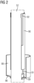
- Figur 2:
- Schnitt durch einen Bewegkontaktstab mit Hülse und Balgkappe mit einem Balgschirm;
- Figur 3:
- Perspektivische Ansicht einer geführten Hülse in einem Bewegkontaktlager;
- Figur 4:
- Perspektivische Darstellung eines Bewegkontaktes mit Hülse und Führungselementen.
- Die
Figur 1 zeigt einen Schnitt durch eine Vakuumschaltröhre 10 mit erfindungsgemäßer Hülse 90. Die Vakuumschaltröhre 10 weist dabei Isolierelemente 20 auf, die hier optional im Bereich der Kontaktscheiben durch ein Zwischenelement 25 beabstandet sind. - Weiter verfügt die Vakuumschaltröhre 10 über einen Festkontakt 30, hier bestehend aus einem Festkontaktstab 32, einem Festkontaktkörper 35 und einer Festkontaktscheibe 34. Der Festkontakt 30 ist an einem Ende der Vakuumschaltröhre 10 mit einem Festkontaktflansch 40 an einem Isolierkörper 20 befestigt.
- Ein Bewegkontakt 50 der Vakuumschaltröhre 10 ist dem Festkontakt 20 gegenüberliegend angeordnet, wobei der Bewegkontakt 50 hier beispielhaft aus einem Bewegkontaktstab 52, einem Bewegkontaktkörper 55 und einer Bewegkontaktkontaktscheibe 54 besteht.
- Auf dem Bewegkontakt 50, genauer auf dem Bewegkontaktstab 52, ist eine Hülse 90 befestigt und diese Hülse 90 ist durch ein Bewegkontaktlager 70 am Bewegkontaktflansch 60 aus dem Balg heraus geführt. Die Hülse 90 ist in dem hier gezeigten Beispiel zwischen dem Bewegkontaktstab 52 und der Balgkappe 86 festgepresst. Damit wird die Hülse 90 auf dem Bewegkontakt 52 derart fixiert, dass es bei einer Bewegung des Bewegkontaktes 50 entlang der Längsachse 56 des Bewegkontakts 50 nicht zu einer Relativbewegung zwischen der Hülse 90 und dem Bewegkontakt 50 kommt. Der Balg 80, der eine Bewegung des Bewegkontakts 50 innerhalb der Vakuumschaltröhre 10 ermöglicht, ist mit einem ersten Ende 82 des Balgs 80 am Bewegkontaktflansch 60 befestigt. Das zweite Ende 84 des Balgs 80 ist in der Figur 1 an der Balgkappe 86 befestigt und die Balgkappe 86 ist wiederum am Bewegkontaktstab 52 des Bewegkontakts 50 befestigt. Die Balgkappe 86 verfügt in der
Figur 1 über einen optionalen Balgschirm 88, der sich von der Balgkappe 86 entlang des Balgs 80 in Richtung des Bewegkontaktflansches 60 erstreckt. - Die
Figur 2 zeigt einen Bewegkontaktstab 52 mit einer Hülse 90, die in Richtung des Pfeils 91 in den Einpressbereich 89 zwischen dem Bewegkontaktstab 52 und der Balgkappe 86 eingepresst wird. Optional kann dieser Einpressbereich 89 auch durch eine Verdickung des Bewegkontaktstabes gebildet sein. Des Weiteren verfügt die Balgkappe 86 über einen Balgschirm 88, wie er in derFigur 1 gezeigt ist. - Die
Figur 3 zeigt einen Teil eines Bewegkontaktstabes 52 mit einem dritten Führungselement 53, einer Hülse 90 mit einem vierten Führungselement 94 und einem zweiten Führungselement 92 in der Hülse 90, das mit dem hier nicht, aber inFigur 4 , gezeigten ersten Führungselement 72 des Bewegkontaktlagers 70 zusammenwirkt. - Die
Figur 4 zeigt eine Hülse 90 in einem Bewegkontaktlager 70, wobei die Hülse 90 zwei zweite Führungselemente 92, 92' aufweist und das Bewegkontaktlager 70 zwei korrespondierende erste Führungselemente 72, 72' aufweist. Die ersten Führungselemente 72, 72' sind hier als Nuteingriffe, also feste Strukturelemente, ausgeführt. Die zweiten Führungselemente 92, 92' sind in diesem Beispiel als Nut ausgeführt. Die Nut 92 erstreckt sich dabei über die gesamte Länger der Hülse 90, sondern ist an einem Ende begrenzt, wodurch ein Herausrutschen der Hülse 90 und des nicht gezeigten Bewegkontakts 50, der mit der Hülse 90 verbunden ist, durch das Bewegkontaktlager 70 verhindert wird. -
- 10
- Vakuumschaltröhre
- 20
- Isolierkörper
- 25
- Zwischenelement
- 30
- Festkontakt
- 32
- Festkontaktstab
- 34
- Festkontaktkontaktscheibe
- 35
- Festkontaktkörper
- 40
- Festkontaktflansch
- 50
- Bewegkontakt
- 52
- Bewegkontaktstab
- 53
- drittes Führungselement
- 54
- Bewegkontaktkontaktscheibe
- 55
- Bewegkontaktkörper
- 56
- Längsachse des Bewegkontakts
- 60
- Bewegkontaktflansch
- 70
- Bewegkontaktlager
- 72
- erstes Führungselement
- 72'
- weiteres erstes Führungselement
- 80
- Balg
- 82
- erstes Balgende
- 84
- zweites Balgende
- 86
- Balgkappe
- 88
- Balgschirm
- 89
- Einpressbereich
- 90
- Hülse
- 91
- Pfeil für die Richtung der Einpressung der Hülse 90
- 92
- zweites Führungselement
- 92'
- weiteres zweites Führungselement
- 94
- Viertes Führungselement
Claims (9)
- Vakuumschaltröhre (10), mit mindestens einem Isolierkörper (20), einem Festkontakt (30), einem Festkontaktflansch (40), einem Bewegkontakt (50) mit einer Längsachse (56), einem Bewegkontaktflansch (60), einem Bewegkontaktlager (70), einem Balg (80), wobei der Festkontakt (30) ortsfest in dem Festkontaktflansch (40) angeordnet ist, der Bewegkontakt (50) beweglich in dem Bewegkontaktlager (70) geführt ist und der Bewegkontakt durch den Balg (80) beweglich am Bewegkontaktflansch (60) befestigt ist, wobei der Balg (80) mit einem ersten Balgende (82) am Bewegkontaktflansch (60) befestigt ist und der Balg (80) mit einem zweiten Balgende (84) am Bewegkontakt (50) befestigt ist, wobei durch eine auf dem Bewegkontakt (50) gegen Bewegungen entlang der Längsachse (56) des Bewegkontaktes (50) fixierte Hülse (90) eine erhöhte Druckfestigkeit der Vakuumschaltröhre (10) gegen Umgebungsdrücke über 2 bar erreicht wird, die derart ausgestaltet und durch das Bewegkontaktlager (70) geführt ist, dass der Bewegkontakt (50) einen Bewegkontaktstab (52) und eine Bewegkontaktkontaktscheibe (54) aufweist, wobei die Hülse (90) derart auf dem Bewegkontakt (50) angeordnet ist, dass sich die Hülse (90) vom zweiten Balgende (84) aus durch das Bewegkontaktlager (70) erstreckt und durch das Bewegkontaktlager (70) am Bewegkontaktflansch (60) aus dem Balg (80) heraus geführt ist und dass die Hülse (90) mittels eines Befestigungsmittels (95) derart auf dem Bewegkontakt (50) fixiert ist, dass bei der Bewegung des Bewegkontaktes (50) keine Relativbewegung entlang der Längsachse (56) des Bewegkontaktes (50) zwischen dem Bewegkontakt (50) und der Hülse (90) erfolgt, dadurch gekennzeichnet, dass das zweite Balgende (84) über eine Balgkappe (86) mit dem Bewegkontaktstab (52) verbunden ist und die Hülse (90) im Bereich des zweiten Balgendes (84) und/oder im Bereich der Balgkappe (86) mittels eines Presssitzes, einer Verklinkung, einer Verrastung, einer Verlötung, einer Verschweißung, einer von der Hülse (90) nicht nachgebildeten Verdickung des Bewegkontaktes in der Position auf dem Bewegkontakt (50) fixiert ist.
- Vakuumschaltröhre (10) nach Anspruch 1,
dadurch gekennzeichnet, dass der Presssitz der Hülse zwischen dem zweiten Balgende (84) und dem Bewegkontakt (50) oder zwischen der Balgkappe (86) und dem Bewegkontaktstab (52) erfolgt. - Vakuumschaltröhre (10) nach einem der vorstehenden Ansprüche,
dadurch gekennzeichnet, dass das Bewegkontaktlager (70) mindestens ein erstes Führungselement (72, 72') aufweist und dass die Hülse (90) mindestens ein zweites Führungselement (92, 92') aufweist, wobei das erste Führungselement (72, 72') und das zweite Führungselement (92, 92') derart ineinander greifen, dass ein Verdrehen der Hülse (90) in dem Bewegkontaktlager (70) verhindert wird. - Vakuumschaltröhre (10) nach Anspruch 3,
dadurch gekennzeichnet, dass das erste Führungselement (72) und das zweite Führungselement (92) derart ineinander greifen und sich gegenseitig in der Bewegung begrenzen, dass die Hülse (90) nicht aus dem Bewegkontaktlager (70) gleitet. - Vakuumschaltröhre (10) nach einem der vorstehenden Ansprüche,
dadurch gekennzeichnet , dass der Bewegkontaktstab (52) mindestens ein drittes Führungselement (53) aufweist und die Hülse (90) mindestens ein viertes Führungselement (94) aufweist, die derart zusammenwirken, dass ein Verdrehen der Hülse (90) auf dem Bewegkontaktstab (52) verhindert wird. - Vakuumschaltröhre (10) nach einem der vorstehenden Ansprüche,
dadurch gekennzeichnet , dass die Hülse (90) aus einem Material mit einem niedrigen Reibungskoeffizienten besteht. - Vakuumschaltröhre (10) nach einem der vorstehenden Ansprüche,
dadurch gekennzeichnet , dass die Hülse (90) aus Polytetrafluoroethylen oder einer Abwandlung von Polytetrafluoroethylen besteht. - Vakuumschaltröhre (10) nach einem der vorstehenden Ansprüche,
dadurch gekennzeichnet, dass das zweite Balgende (84) und/oder die Balgkappe (86) weiter über einen Balgschirm (88) verfügen. - Vakuumschaltröhre (10) nach Anspruch 8,
dadurch gekennzeichnet, dass sich der Balgschirm (88) von dem zweiten Balgende (84) in Richtung des Bewegkontaktflansches (60) erstreckt.
Applications Claiming Priority (2)
| Application Number | Priority Date | Filing Date | Title |
|---|---|---|---|
| DE102017222406.1A DE102017222406A1 (de) | 2017-12-11 | 2017-12-11 | Vakuumschaltröhre |
| PCT/EP2018/081927 WO2019115178A1 (de) | 2017-12-11 | 2018-11-20 | Vakuumschaltröhre |
Publications (3)
| Publication Number | Publication Date |
|---|---|
| EP3724907A1 EP3724907A1 (de) | 2020-10-21 |
| EP3724907C0 EP3724907C0 (de) | 2025-06-25 |
| EP3724907B1 true EP3724907B1 (de) | 2025-06-25 |
Family
ID=64661273
Family Applications (1)
| Application Number | Title | Priority Date | Filing Date |
|---|---|---|---|
| EP18815523.8A Active EP3724907B1 (de) | 2017-12-11 | 2018-11-20 | Vakuumschaltröhre |
Country Status (6)
| Country | Link |
|---|---|
| US (1) | US11676784B2 (de) |
| EP (1) | EP3724907B1 (de) |
| JP (1) | JP7179864B2 (de) |
| CN (1) | CN111448635B (de) |
| DE (1) | DE102017222406A1 (de) |
| WO (1) | WO2019115178A1 (de) |
Families Citing this family (5)
| Publication number | Priority date | Publication date | Assignee | Title |
|---|---|---|---|---|
| US11842871B2 (en) * | 2021-09-15 | 2023-12-12 | Eaton Intelligent Power Limited | Low voltage MEMS relay filled with alternative gas mixture to SF6 |
| DE102021210270B4 (de) | 2021-09-16 | 2025-01-30 | Siemens Aktiengesellschaft | Vakuumschalteinrichtung |
| DE102021210859A1 (de) * | 2021-09-28 | 2023-03-30 | Siemens Aktiengesellschaft | Gehäuse für eine Vakuumschaltröhre |
| JP7361986B1 (ja) * | 2022-08-29 | 2023-10-16 | 三菱電機株式会社 | 真空バルブ及び真空遮断器 |
| WO2025173065A1 (ja) * | 2024-02-13 | 2025-08-21 | 三菱電機株式会社 | 真空遮断器及び真空遮断器の製造方法 |
Family Cites Families (26)
| Publication number | Priority date | Publication date | Assignee | Title |
|---|---|---|---|---|
| US2981813A (en) * | 1958-07-21 | 1961-04-25 | Jennings Radio Mfg Corp | Vacuum switch |
| US3178542A (en) * | 1962-03-26 | 1965-04-13 | Jennings Radio Mfg Corp | Vacuum switch and internal shielding therefor |
| CH436421A (de) * | 1963-04-09 | 1967-11-15 | Jennings Radio Manufacturing C | Leistungsschalter |
| GB1218357A (en) * | 1967-04-13 | 1971-01-06 | English Electric Co Ltd | Improvements in or relating to bellows |
| US4039792A (en) * | 1975-12-19 | 1977-08-02 | General Electric Company | Compact high-current vacuum circuit interrupter comprising a metal housing that is electrically connected to one contact of the interrupter |
| JPS52137073U (de) * | 1976-04-14 | 1977-10-18 | ||
| JPS5324465U (de) * | 1976-08-09 | 1978-03-01 | ||
| JPS5828119A (ja) * | 1981-08-13 | 1983-02-19 | 株式会社東芝 | 真空バルブ |
| US4492837A (en) * | 1983-03-21 | 1985-01-08 | General Electric Company | Guide means for the movable contact rod of a vacuum interrupter |
| JPS6289740U (de) * | 1985-11-26 | 1987-06-09 | ||
| FR2660792B1 (fr) | 1990-04-04 | 1992-06-12 | Alsthom Gec | Disjoncteur a haute ou moyenne tension a contacts d'arc en bout. |
| CH686326A5 (de) | 1993-08-27 | 1996-02-29 | Secheron Sa | Schalter mit einer Vakuumschaltroehre. |
| EP0660354B1 (de) * | 1993-12-24 | 1997-11-19 | ABBPATENT GmbH | Vakuumschaltkammer |
| KR100295905B1 (ko) * | 1998-07-18 | 2001-08-07 | 이종수 | 진공인터럽터용전극구조체 |
| JP4031895B2 (ja) * | 2000-02-09 | 2008-01-09 | 日本特殊陶業株式会社 | 釉薬層付きセラミック部材を用いた金属−セラミック接合体及びそれを用いた真空スイッチユニット |
| KR100386845B1 (ko) * | 2000-10-16 | 2003-06-09 | 엘지산전 주식회사 | 종자계 방식 진공인터럽터용 전극구조 |
| JP4818530B2 (ja) * | 2001-04-19 | 2011-11-16 | 三菱電機株式会社 | 真空バルブ |
| JP2004241373A (ja) * | 2003-01-16 | 2004-08-26 | Fuji Electric Fa Components & Systems Co Ltd | 真空バルブ |
| JP2005339865A (ja) * | 2004-05-25 | 2005-12-08 | Mitsubishi Electric Corp | 真空バルブ |
| JP4667032B2 (ja) * | 2004-12-10 | 2011-04-06 | 三菱電機株式会社 | 真空バルブ |
| JP5317896B2 (ja) | 2009-09-04 | 2013-10-16 | 株式会社東芝 | 真空バルブおよびガス絶縁負荷時タップ切換器 |
| WO2011138819A1 (ja) * | 2010-05-07 | 2011-11-10 | 三菱電機株式会社 | 真空バルブ |
| JP5566535B2 (ja) * | 2011-05-30 | 2014-08-06 | 三菱電機株式会社 | 真空バルブ |
| DE102012211475B4 (de) * | 2012-07-03 | 2019-11-21 | Siemens Aktiengesellschaft | Vakuumschaltröhre |
| CN205248178U (zh) * | 2015-12-02 | 2016-05-18 | 北京京森源电器有限公司 | 一种防扭真空灭弧室 |
| DE102016002261A1 (de) * | 2016-02-25 | 2017-08-31 | Siemens Aktiengesellschaft | Anordnung und Verfahren zum Führen einer Schaltstange eines Hochspannungs-Leistungsschalters |
-
2017
- 2017-12-11 DE DE102017222406.1A patent/DE102017222406A1/de active Pending
-
2018
- 2018-11-20 US US16/771,801 patent/US11676784B2/en active Active
- 2018-11-20 EP EP18815523.8A patent/EP3724907B1/de active Active
- 2018-11-20 CN CN201880079716.1A patent/CN111448635B/zh active Active
- 2018-11-20 JP JP2020549872A patent/JP7179864B2/ja active Active
- 2018-11-20 WO PCT/EP2018/081927 patent/WO2019115178A1/de not_active Ceased
Also Published As
| Publication number | Publication date |
|---|---|
| EP3724907C0 (de) | 2025-06-25 |
| EP3724907A1 (de) | 2020-10-21 |
| US20210074494A1 (en) | 2021-03-11 |
| WO2019115178A1 (de) | 2019-06-20 |
| US11676784B2 (en) | 2023-06-13 |
| DE102017222406A1 (de) | 2019-06-13 |
| CN111448635A (zh) | 2020-07-24 |
| CN111448635B (zh) | 2023-07-14 |
| JP7179864B2 (ja) | 2022-11-29 |
| JP2021506095A (ja) | 2021-02-18 |
Similar Documents
| Publication | Publication Date | Title |
|---|---|---|
| DE102017103508B3 (de) | Leiteranschlussklemme | |
| EP3423744B1 (de) | Vorpositionierer für eine profilschelle und verbindungsanordnung mit einem derartigen vorpositionierer | |
| DE102017222406A1 (de) | Vakuumschaltröhre | |
| DE102012101709B4 (de) | Steckverbinder | |
| WO2003067713A1 (de) | Rekontaktierbare verbindungsanordnung | |
| DE102014102662A1 (de) | Steckverbindung für Fluid-Leitungen und Halteteil für eine derartige Steckverbindung | |
| DE102013100772A1 (de) | Steckverbindung für Fluid-Leitungen und Halteteil für eine derartige Steckverbindung | |
| EP1991796B1 (de) | Kugelgelenk | |
| WO1998059183A1 (de) | Gleitverbindung | |
| WO2006122603A1 (de) | Lenkgetriebe | |
| EP1983629B1 (de) | Kabelverschraubung | |
| DE102011008927B4 (de) | Gleitringdichtungsanordnung mit Federringscheibe | |
| EP1686294B1 (de) | Schaltgabel mit Gleitschuhring und entsprechende Gleitschuhanordnung | |
| DE3940647C2 (de) | ||
| DE60017142T2 (de) | Dichtungsanordnung und dichtungselement dafür | |
| BE1014553A3 (de) | Kontaktanordnung fur gleit-und steckkontakte elektrischer gerate und anlagen, insbesondere der elektrischen energietechnick, sowie steuer-und regelungstechnik. | |
| DE102008059159A1 (de) | Gleitplatte und Zahnstangenführung für eine Zahnstangengetriebelenkvorrichtung | |
| DE102006051688B4 (de) | Rotationsdämpfer | |
| DE102008035043B4 (de) | Mikroschalter | |
| DE102021210270B4 (de) | Vakuumschalteinrichtung | |
| DE102012101126B4 (de) | Elektrischer Drucktaster mit einem Dichtbalg und einer den Dichtbalg beaufschlagenden Feder sowie Verfahren zu dessen Montage | |
| DE102019215967A1 (de) | Schaltbaugruppe | |
| DE2448065B2 (de) | Thermostatisches betaetigungselement | |
| DE102015000584A1 (de) | Rastschalter für ein Kraftfahrzeug und Rastbolzenanordnung für den Rastschalter | |
| DE19629204A1 (de) | Vakuumschaltkammer |
Legal Events
| Date | Code | Title | Description |
|---|---|---|---|
| STAA | Information on the status of an ep patent application or granted ep patent |
Free format text: STATUS: UNKNOWN |
|
| STAA | Information on the status of an ep patent application or granted ep patent |
Free format text: STATUS: THE INTERNATIONAL PUBLICATION HAS BEEN MADE |
|
| PUAI | Public reference made under article 153(3) epc to a published international application that has entered the european phase |
Free format text: ORIGINAL CODE: 0009012 |
|
| STAA | Information on the status of an ep patent application or granted ep patent |
Free format text: STATUS: REQUEST FOR EXAMINATION WAS MADE |
|
| 17P | Request for examination filed |
Effective date: 20200519 |
|
| AK | Designated contracting states |
Kind code of ref document: A1 Designated state(s): AL AT BE BG CH CY CZ DE DK EE ES FI FR GB GR HR HU IE IS IT LI LT LU LV MC MK MT NL NO PL PT RO RS SE SI SK SM TR |
|
| AX | Request for extension of the european patent |
Extension state: BA ME |
|
| DAV | Request for validation of the european patent (deleted) | ||
| DAX | Request for extension of the european patent (deleted) | ||
| RAP1 | Party data changed (applicant data changed or rights of an application transferred) |
Owner name: SIEMENS ENERGY GLOBAL GMBH & CO. KG |
|
| STAA | Information on the status of an ep patent application or granted ep patent |
Free format text: STATUS: EXAMINATION IS IN PROGRESS |
|
| 17Q | First examination report despatched |
Effective date: 20220722 |
|
| GRAP | Despatch of communication of intention to grant a patent |
Free format text: ORIGINAL CODE: EPIDOSNIGR1 |
|
| STAA | Information on the status of an ep patent application or granted ep patent |
Free format text: STATUS: GRANT OF PATENT IS INTENDED |
|
| INTG | Intention to grant announced |
Effective date: 20250131 |
|
| GRAS | Grant fee paid |
Free format text: ORIGINAL CODE: EPIDOSNIGR3 |
|
| GRAA | (expected) grant |
Free format text: ORIGINAL CODE: 0009210 |
|
| STAA | Information on the status of an ep patent application or granted ep patent |
Free format text: STATUS: THE PATENT HAS BEEN GRANTED |
|
| AK | Designated contracting states |
Kind code of ref document: B1 Designated state(s): AL AT BE BG CH CY CZ DE DK EE ES FI FR GB GR HR HU IE IS IT LI LT LU LV MC MK MT NL NO PL PT RO RS SE SI SK SM TR |
|
| REG | Reference to a national code |
Ref country code: GB Ref legal event code: FG4D Free format text: NOT ENGLISH |
|
| REG | Reference to a national code |
Ref country code: CH Ref legal event code: EP |
|
| REG | Reference to a national code |
Ref country code: CH Ref legal event code: EP |
|
| REG | Reference to a national code |
Ref country code: IE Ref legal event code: FG4D Free format text: LANGUAGE OF EP DOCUMENT: GERMAN |
|
| REG | Reference to a national code |
Ref country code: DE Ref legal event code: R096 Ref document number: 502018015910 Country of ref document: DE |
|
| U01 | Request for unitary effect filed |
Effective date: 20250625 |
|
| U07 | Unitary effect registered |
Designated state(s): AT BE BG DE DK EE FI FR IT LT LU LV MT NL PT RO SE SI Effective date: 20250701 |
|
| PG25 | Lapsed in a contracting state [announced via postgrant information from national office to epo] |
Ref country code: GR Free format text: LAPSE BECAUSE OF FAILURE TO SUBMIT A TRANSLATION OF THE DESCRIPTION OR TO PAY THE FEE WITHIN THE PRESCRIBED TIME-LIMIT Effective date: 20250926 |
|
| PG25 | Lapsed in a contracting state [announced via postgrant information from national office to epo] |
Ref country code: HR Free format text: LAPSE BECAUSE OF FAILURE TO SUBMIT A TRANSLATION OF THE DESCRIPTION OR TO PAY THE FEE WITHIN THE PRESCRIBED TIME-LIMIT Effective date: 20250625 |
|
| PG25 | Lapsed in a contracting state [announced via postgrant information from national office to epo] |
Ref country code: RS Free format text: LAPSE BECAUSE OF FAILURE TO SUBMIT A TRANSLATION OF THE DESCRIPTION OR TO PAY THE FEE WITHIN THE PRESCRIBED TIME-LIMIT Effective date: 20250925 |
|
| U20 | Renewal fee for the european patent with unitary effect paid |
Year of fee payment: 8 Effective date: 20251126 |
|
| PG25 | Lapsed in a contracting state [announced via postgrant information from national office to epo] |
Ref country code: IS Free format text: LAPSE BECAUSE OF FAILURE TO SUBMIT A TRANSLATION OF THE DESCRIPTION OR TO PAY THE FEE WITHIN THE PRESCRIBED TIME-LIMIT Effective date: 20251025 |
|
| PGFP | Annual fee paid to national office [announced via postgrant information from national office to epo] |
Ref country code: GB Payment date: 20251125 Year of fee payment: 8 |
|
| PGFP | Annual fee paid to national office [announced via postgrant information from national office to epo] |
Ref country code: NO Payment date: 20251120 Year of fee payment: 8 |
|
| PG25 | Lapsed in a contracting state [announced via postgrant information from national office to epo] |
Ref country code: SM Free format text: LAPSE BECAUSE OF FAILURE TO SUBMIT A TRANSLATION OF THE DESCRIPTION OR TO PAY THE FEE WITHIN THE PRESCRIBED TIME-LIMIT Effective date: 20250625 |
|
| PG25 | Lapsed in a contracting state [announced via postgrant information from national office to epo] |
Ref country code: CZ Free format text: LAPSE BECAUSE OF FAILURE TO SUBMIT A TRANSLATION OF THE DESCRIPTION OR TO PAY THE FEE WITHIN THE PRESCRIBED TIME-LIMIT Effective date: 20250625 |
|
| PG25 | Lapsed in a contracting state [announced via postgrant information from national office to epo] |
Ref country code: PL Free format text: LAPSE BECAUSE OF FAILURE TO SUBMIT A TRANSLATION OF THE DESCRIPTION OR TO PAY THE FEE WITHIN THE PRESCRIBED TIME-LIMIT Effective date: 20250625 |
|
| PG25 | Lapsed in a contracting state [announced via postgrant information from national office to epo] |
Ref country code: SK Free format text: LAPSE BECAUSE OF FAILURE TO SUBMIT A TRANSLATION OF THE DESCRIPTION OR TO PAY THE FEE WITHIN THE PRESCRIBED TIME-LIMIT Effective date: 20250625 |
|
| PG25 | Lapsed in a contracting state [announced via postgrant information from national office to epo] |
Ref country code: ES Free format text: LAPSE BECAUSE OF FAILURE TO SUBMIT A TRANSLATION OF THE DESCRIPTION OR TO PAY THE FEE WITHIN THE PRESCRIBED TIME-LIMIT Effective date: 20250625 |
|
| PLBE | No opposition filed within time limit |
Free format text: ORIGINAL CODE: 0009261 |
|
| STAA | Information on the status of an ep patent application or granted ep patent |
Free format text: STATUS: NO OPPOSITION FILED WITHIN TIME LIMIT |
|
| REG | Reference to a national code |
Ref country code: CH Ref legal event code: L10 Free format text: ST27 STATUS EVENT CODE: U-0-0-L10-L00 (AS PROVIDED BY THE NATIONAL OFFICE) Effective date: 20260507 |