EP3724403B1 - Protection device and road barrier for motorcyclists - Google Patents
Protection device and road barrier for motorcyclists Download PDFInfo
- Publication number
- EP3724403B1 EP3724403B1 EP18833518.6A EP18833518A EP3724403B1 EP 3724403 B1 EP3724403 B1 EP 3724403B1 EP 18833518 A EP18833518 A EP 18833518A EP 3724403 B1 EP3724403 B1 EP 3724403B1
- Authority
- EP
- European Patent Office
- Prior art keywords
- barrier
- protection device
- superior
- spacer
- fastening
- Prior art date
- Legal status (The legal status is an assumption and is not a legal conclusion. Google has not performed a legal analysis and makes no representation as to the accuracy of the status listed.)
- Active
Links
Images


Classifications
-
- E—FIXED CONSTRUCTIONS
- E01—CONSTRUCTION OF ROADS, RAILWAYS, OR BRIDGES
- E01F—ADDITIONAL WORK, SUCH AS EQUIPPING ROADS OR THE CONSTRUCTION OF PLATFORMS, HELICOPTER LANDING STAGES, SIGNS, SNOW FENCES, OR THE LIKE
- E01F15/00—Safety arrangements for slowing, redirecting or stopping errant vehicles, e.g. guard posts or bollards; Arrangements for reducing damage to roadside structures due to vehicular impact
- E01F15/02—Continuous barriers extending along roads or between traffic lanes
- E01F15/04—Continuous barriers extending along roads or between traffic lanes essentially made of longitudinal beams or rigid strips supported above ground at spaced points
- E01F15/0407—Metal rails
- E01F15/0423—Details of rails
- E01F15/043—Details of rails with multiple superimposed members; Rails provided with skirts
-
- E—FIXED CONSTRUCTIONS
- E01—CONSTRUCTION OF ROADS, RAILWAYS, OR BRIDGES
- E01F—ADDITIONAL WORK, SUCH AS EQUIPPING ROADS OR THE CONSTRUCTION OF PLATFORMS, HELICOPTER LANDING STAGES, SIGNS, SNOW FENCES, OR THE LIKE
- E01F15/00—Safety arrangements for slowing, redirecting or stopping errant vehicles, e.g. guard posts or bollards; Arrangements for reducing damage to roadside structures due to vehicular impact
- E01F15/14—Safety arrangements for slowing, redirecting or stopping errant vehicles, e.g. guard posts or bollards; Arrangements for reducing damage to roadside structures due to vehicular impact specially adapted for local protection, e.g. for bridge piers, for traffic islands
- E01F15/145—Means for vehicle stopping using impact energy absorbers
- E01F15/146—Means for vehicle stopping using impact energy absorbers fixed arrangements
-
- E—FIXED CONSTRUCTIONS
- E01—CONSTRUCTION OF ROADS, RAILWAYS, OR BRIDGES
- E01F—ADDITIONAL WORK, SUCH AS EQUIPPING ROADS OR THE CONSTRUCTION OF PLATFORMS, HELICOPTER LANDING STAGES, SIGNS, SNOW FENCES, OR THE LIKE
- E01F8/00—Arrangements for absorbing or reflecting air-transmitted noise from road or railway traffic
- E01F8/0005—Arrangements for absorbing or reflecting air-transmitted noise from road or railway traffic used in a wall type arrangement
- E01F8/0023—Details, e.g. foundations
-
- E—FIXED CONSTRUCTIONS
- E01—CONSTRUCTION OF ROADS, RAILWAYS, OR BRIDGES
- E01F—ADDITIONAL WORK, SUCH AS EQUIPPING ROADS OR THE CONSTRUCTION OF PLATFORMS, HELICOPTER LANDING STAGES, SIGNS, SNOW FENCES, OR THE LIKE
- E01F15/00—Safety arrangements for slowing, redirecting or stopping errant vehicles, e.g. guard posts or bollards; Arrangements for reducing damage to roadside structures due to vehicular impact
- E01F15/02—Continuous barriers extending along roads or between traffic lanes
- E01F15/08—Continuous barriers extending along roads or between traffic lanes essentially made of walls or wall-like elements ; Cable-linked blocks
- E01F15/081—Continuous barriers extending along roads or between traffic lanes essentially made of walls or wall-like elements ; Cable-linked blocks characterised by the use of a specific material
- E01F15/085—Continuous barriers extending along roads or between traffic lanes essentially made of walls or wall-like elements ; Cable-linked blocks characterised by the use of a specific material using metal
-
- E—FIXED CONSTRUCTIONS
- E01—CONSTRUCTION OF ROADS, RAILWAYS, OR BRIDGES
- E01F—ADDITIONAL WORK, SUCH AS EQUIPPING ROADS OR THE CONSTRUCTION OF PLATFORMS, HELICOPTER LANDING STAGES, SIGNS, SNOW FENCES, OR THE LIKE
- E01F8/00—Arrangements for absorbing or reflecting air-transmitted noise from road or railway traffic
- E01F8/0005—Arrangements for absorbing or reflecting air-transmitted noise from road or railway traffic used in a wall type arrangement
- E01F8/0047—Arrangements for absorbing or reflecting air-transmitted noise from road or railway traffic used in a wall type arrangement with open cavities, e.g. for covering sunken roads
- E01F8/0064—Perforated plate or mesh, e.g. as wall facing
- E01F8/007—Perforated plate or mesh, e.g. as wall facing with damping material
Definitions
- the invention is in the field of road barriers installed on roadsides and/or highway sides.
- the invention refers more particularly to a protection device and a kit for the assembling of the protection device for motorcyclists adapted to be installed on a road barrier, in order to better protect motorcyclists who would collide with the barrier.
- Road barriers are well known and comprise at least one longitudinal metallic rail, kept at a distance from the ground by a plurality of poles set in roadsides and spaced out regularly. These barriers form smooth retention devices which deform themselves in the event of an impact with a vehicle. Part of the energy from the impact is then absorbed during the deformation of the barrier, therefore limiting the damage to the vehicle exiting the road.
- the document EP2450489 discloses a protection system for motorcyclists, adapted to be secured to the road safety barrier.
- the protection system comprises a beam extending longitudinally between the rail and the ground to protect the rider from poles. This beam is kept at a distance from the poles by a plurality of anchoring means, each anchoring means being secured to a pole and extending in the direction of the pole axis.
- the invention is to provide a protection device for motorcyclists, adapted to be secured to the road safety barrier, and adapted to protect motorcyclists from the poles of the road barrier at all times while efficiently containing them / slowing them down.
- the protection device for motorcyclists is adapted to be secured to a road safety barrier with a plurality of poles regularly spaced out and comprises a longitudinal beam and a spacer extending longitudinally all along the rear side of at least one part of said beam and adapted to be secured to said poles, wherein the beam and the spacer are assembled together so as to define, in said part of the beam, a longitudinal damping volume with a closed cross-section, so as to spread the strain along the device in the event of an impact to limit the transversal deformation of the beam and to maintain it at a distance from the poles of the road barrier.
- the spacer comprises a central fastening section to said poles from which extend two legs respectively superior and inferior whose open ends are fastened to the beam, the inferior leg and the superior leg being at an angle ⁇ comprised between 60° and 100° and the inferior leg and the central fastening section being at an angle ⁇ comprised between 105° and 145°.
- the invention is to also provide a road safety barrier comprising a longitudinal rail secured to a plurality of poles set in the ground and regularly spaced out, and which is essentially characterised in that it comprises a protection device for motorcyclists as described above.
- the invention is to also provide a protection kit for the assembling of a protection device for motorcyclist, adapted to be secured to a road safety barrier with a plurality of poles regularly spaced out, the kit comprising a first profiled sheet forming a longitudinal beam, a second profiled sheet forming a spacer, wherein the beam and the spacer are adapted to be assembled together, with the spacer extending longitudinally all along the rear side of said beam, so as to define a longitudinal damping volume with a closed cross-section, wherein the spacer comprises a central fastening section to said poles from which extend two legs respectively superior and inferior whose open ends are adapted to be fastened to the beam, the inferior leg and the superior leg being at an angle ⁇ comprised between 60° and 100° and the inferior leg and the central fastening section being at an angle ⁇ comprised between 105° and 145°.
- road barriers include a usually metallic rail extending longitudinally, that is parallel to the ground. This rail is secured to poles set in the ground and regularly spaced out, so that the rail is kept at a distance from the ground.
- the present invention provides a protection device 5a, 5a', 5b for motorcyclists adapted to be secured to a road barrier, which in the event of an impact presents a deformation of sufficiently low amplitude to remain at a distance from the poles at all times.
- the motorcyclist who will then hit the protection device 5a, 5a', 5b of the invention following a fall will not collide with the poles of the barrier.
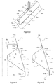
- the road barrier 1 comprises a longitudinal metallic rail 2 (partially illustrated), with a W-shaped cross-section for example.
- the barrier 1 further comprises a plurality of poles 3 set in the ground 4 and regularly spaced out, the poles 3 being all parallel to each other. Each pole 3 thus extends perpendicularly to the rail 2 according to a pole axis X-X.
- the term “vertical” will be used to designate the pole axis and more generally all direction perpendicular to the ground 4
- the term “horizontal” will be used for the elements of barrier 1 which extend longitudinally, that is parallel to ground 4.
- the road barrier 1 comprises a protection device 5a for motorcyclists according to a first embodiment.
- the protection device 5a comprises a longitudinal beam 6a, thus extending itself horizontally and which is secured to the poles 3 of the barrier 1 by means of a longitudinal spacer 7a.
- This spacer 7a has the function of maintaining the beam 6a at a distance from the poles 3 at all times, particularly by absorbing more efficiently the impact energy as will be showed in more details later. Thanks to the longitudinal beam 6a and to the longitudinal spacer 7a, the beam 6a stays sufficiently distant from the poles 3 of the road barrier to protect motorcyclists from these poles 3 at all times while efficiently containing them and/or slowing them down, even in the event of a violent impact caused by a motorcyclist colliding with the beam 6a and generating an important transversal deformation of beam 6a.
- the spacer 7a extends horizontally along one part of the beam 6a, preferably on more than 50% of the beam, more preferably on more than 70% of the beam and even more preferably all along the beam 6a.
- the spacer 7a extends over the pole 3, preferably extends of at least one meter on both sides of the pole 3.
- the beam 6a and the spacer 7a are formed respectively by first and second profiled metallic sheets, preferably obtained by roll-forming or bending.
- the steel constituting the first and second sheets presents preferably an average elastic limit of approximately 260 MPa, a great resistance to impacts and an elongation at break of at least 26%.
- the steel thus also presents a good resistance to corrosion.
- the steel preferably comprises a Magnelis® type metallic coating produced in a hot-dip galvanising line in a molten bath comprising 2.5-3.5% in magnesium and 3-4% in aluminium.
- the beam 6a comprises a central planar section 8 prolonged by two end parts 9a, 10a, forming fastening sections to the spacer 7a, respectively inferior fastening section 9a and superior fastening section 10a.
- the central section 8a is inclined relative to the pole axis X-X, at an angle of 10° to 25°, preferably 10° to 20°, more preferably of 16°.
- the beam 6a transversally extends itself away from the pole axis X-X as it reaches closer to the ground 4.
- the inferior section of the beam 6a corresponding to the inferior fastening section 9a which is the closest to the ground 4, is further away from the poles 3 then the superior section of said beam 6a, forming the superior fastening section 10a located in front of the rail 2.
- the central section 8 being planar, its deformation during impact is homogeneous in its height and stiffened areas and/or preferential deformations in weak points are avoided. This helps absorbing the energy from the impact. In particular, it doesn't comprise any inwards bend as it would project the motorcyclist in the air towards the longitudinal rail 2 of the road safety barrier.
- the inferior fastening section 9a of the beam 6a further preferably comprises a flap 11a to enable it to lay on the ground 4. Thanks to that, the protection device 5a is more stable. In addition, there are no space between the ground and the beam 6a, preventing a sliding rider from coming into contact with any potential hazard that may be behind the beam 6a. As illustrated in figure 1 , the inferior fastening section 9a is bent at an angle of 90°. As the flap 11a is horizontal, the inferior fastening section9 thus extends itself vertically towards the central inclined section 8a of the beam 6a. The flap 11a is not fastened to the ground so that the deformation during impact is not prevented.
- the superior fastening section 10a also preferably comprises a flap 12a whose open end engages the rail 2. This flap 12a thus ensures continuity between the rail 2 and the protection device 5a. As illustrated in figure 1 , the superior fastening section 10a is bent at an obtuse angle. The flap 12a is horizontal and the superior fastening section 10a extends itself beyond the bend towards the central inclined section in the same plane as the latter.
- the spacer 7a is from a sectional view generally V-shaped, and comprises a central section 13a of fastening to the poles 3 from which extend two legs respectively superior 140a and inferior 141a towards and to the inner surface 32a of the beam 6a.
- the superior leg 140a and the inferior leg 141a are inclined above and below a horizontal axis parallel to the road.
- the inferior leg 141a and the central fastening section 13 are at an angle ⁇ of 105° to 145°, preferably of 115° to 135°.
- the superior leg 140a and the central fastening section 13 are at an angle ⁇ of 105° to 165°, preferably of 115° to 135°.
- both legs 140a, 141a are at an angle ⁇ of 60° to 90°, preferably of 70°.
- the central fastening section 13a ensures the securing of spacer 7a to the poles 3 by fastening means 17 described further below.
- the central section 13a is thus preferably planar.
- the V-shaped spacer 7a thanks to the inclination of both inferior 140a and superior 141a legs as defined above and thanks to the value of the angles ⁇ , ⁇ and ⁇ , produces a deformation of said legs 140a, 141a in the event of an impact of a motorcyclist against the beam 6a, said deformation leads to an increase of the spacing between the legs 140a, 141a.
- the deformation not only absorbs the energy from the said impact but also generates a spring effect which pushes back the rider who hit the beam 6a away from the poles 3.
- the beam 6a and the spacer 7a work in synergy in case of impact on the protection device 5a to dampen the transversal stresses.
- the inferior leg 141a being oriented below the horizontal plane, it doesn't prevent the protection device from absorbing the impact of the motorcyclist sliding along the horizontal plane.
- Both the superior leg 140a and the inferior leg 141a of the spacer 7a extend from the central fastening section 13a towards an open end forming respectively the superior bracket 150a and inferior bracket 151a to the beam 6a. More specifically, both the superior bracket 150a and inferior bracket 151a are maintained in contact with the inner surface 32a of the beam 6a respectively at the level of the superior fastening section 10a and of the inferior fastening section 9a of the beam 6a.
- the superior bracket 150a and inferior bracket 151a are preferably fasten respectively to the superior fastening section 10a and to the inferior fastening section 9a by bolting 160a,161a.
- the bolts 160a, 161a are preferably regularly spaced in the longitudinal direction of the beam 6a, the space between two bolts 16a0, 161a, respectively at the level of the superior bracket 150a and at the level of the inferior bracket 151a, being around one meter. Thanks to this value of spacing between two successive bolts 160a, 161a, global stability of the fastening between the beam 6a and the spacer 7a is increased.
- the beam 6a and the spacer 7a thus define a damping volume V which extends longitudinally, that is horizontally, along the beam 6a. More specifically, the sides of this damping volume V are defined by the central fastening section 13a and the two legs 140a, 141a of spacer 7a, and by the inclined central section 8a of the beam 6a. In transversal cross-section, the corresponding surface, i.e. defined by the central fastening section 13a and the two legs 140a, 141a of spacer 7a, and by the inclined central section 8a of the beam 6a, is identified as the damping surface S.
- the damping volume V and the corresponding damping surface S the forces generated by the impact on the protection device 5a are well distributed along the sides of the damping volume V.
- the absorption of the impact energy in the protection device 5a is homogenous and wide, which in turn reduces the amplitude of the transversal deformation of the beam 6a.
- the ratio S/(H x W) where S is the damping surface, H the height of the beam 6a (measured along the vertical axis) and W the width of the beam 6a (measured along the horizontal axis) is superior or equal to 0.2, more preferably comprised between 0.2 and 0.4. This improves even further the distribution of the forces generated by the impact on the protection device 5a. As a result, the absorption of the impact energy in the protection device 5a is more homogenous and wider.
- the spacer 7a in the event of an impact, distributes the forces generated by the impact on the protection device 5a (along the sides of the damping volume V) to a large longitudinal extent.
- the absorption of the impact energy in the device 5a is even more homogenous and wider, which in turn reduces the amplitude of the transversal deformation of the beam 6a.
- the protection device 5a of the first embodiment preferably comprises at least one stabilising member 18a formed by a third sheet, preferably obtained by roll-forming or bending.
- the said stabilising member 18a preferably has the same mechanical characteristics than those of the primary and secondary sheets 6a, 7a.
- the stabilising member 18a provides a second fastening point of the beam 6a to the pole 3, thus stabilising the position of the beam 6a in the event of an impact:
- the stabilising member 18a has a U-shaped transversal cross-section presenting:
- the second fastening portion 21a preferably faces at the same time the inner surface 32a of the beam 6a at the level of its superior fastening section 10a and the superior bracket 150a of the spacer 7a.
- the second fastening portion 21a of the stabilising member 18a, the superior bracket 150a of the spacer 7a and the superior fastening section 10a of the beam 6a are thus superimposed and secured together by common securing means, for example a bolt 160a.
- the first fastening portion 20a of the stabilising member 18a is secured to pole 3 by fastening means 17.
- the stabilising member 18a is bent at 90° between the central planar section 19a and the first fastening portion 20a, the latter being parallel to the given vertical pole 3, and bent at an obtuse angle between the central planar section 19a and the second fastening portion 21a, the latter being parallel to the inclined central portion 8a of the beam 6a.
- the second portion of fastening 21a of the stabilising member 18a is thus disposed to rest against the inner surface 32a of the beam 6a at the level of its superior fastening section 10a.
- the U-shaped stabilising member 18a provides an easy installation of the beam 6a on the different types of existing poles 3 of road barriers 1.
- stabilising members 18a of the beam 6a can be as many stabilising members 18a of the beam 6a as they are poles 3. These stabilising members 18a allow the stabilisation of the protection device 5a, as well as maintaining the flap 12a of the superior fastening section 10a of the beam 6a at a constant distance from the poles 3, particularly when the beam 6a is deformed during an impact.
- spacer 7a et beam 6a are the same than those described above.
- the damping volume V is thus the same and damping effect is identical.
- the second particular example does not comprise any stabilising member, which has no effect on damping since said damping effect is provided by the spacer 7 combined with the beam 6a.
- the device 5a' of this second example is a bit less stable when set to the barrier 1 than the device 5a of the first example of the first embodiment.
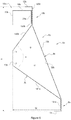
- the protection device 5b in a second embodiment is almost identical to the protection device 5a in the first embodiment, excepting for the superior fastening section 10b of the beam 6b which presents a different configuration and for the angle ⁇ between the legs 140b, 141b.
- the superior fastening section 10b of the beam 6b is now bent at 90° so that the flap 12b is horizontal and superior fastening section 10b extends beyond the bend by a vertical portion 120b.
- the vertical portion 120b and the inclined central portion 8 thus extend themselves into two different planes.
- the junction line between the superior fastening section 10b and the central part 8b of the beam 6b is closer to the poles 3 in this second embodiment.
- the inclination of the central section 8b is more marked.
- the superior leg 140b and inferior leg 141b form an angle ⁇ superior to the one of the first embodiment.
- both legs 140b and 141b are at an angle ⁇ of 70° to 100°, preferably around 90°.
- the angle ⁇ between the inferior leg and the central fastening section has the same value than in the first embodiment.
- the superior leg and the central fastening section form an angle ⁇ inferior to the one of the first embodiment.
- the ratio S/(H x W) is still superior or equal to 0.2, more preferably comprised between 0.2 and 0.4.
- the stabilising member 18b of this second embodiment of the device 5b also has a slightly different configuration. Indeed, the stabilising member 18b is bent at 90° between the central planar section 19b and the second fastening portion 21b to conform to the verticality of the superior fastening section 10b of the beam 6b. The second fastening portion 21b is thus parallel to the given pole 3.
- the protection device 5a, 5a', 5b is included in a trapezoidal shape, in which the larger base length is of 180 to 220 mm, preferably of 200 mm, in which the smaller base is of 60 to 100 mm, preferably of 80 mm, and in which the height of such trapezoidal shape is of 400 to 450 mm, preferably of 430 mm.
- the length of the smaller base represents the distance between the pole 3 and the edge of the superior fastening section 10a,10b which is adjacent to the central section 8a, 8b.
- the length of the smaller base corresponds to the thickness of the rail 2, so that the superior fastening section 10a, 10b is in the continuity of the rail 2.
- the length of the larger base represents the distance between a pole 3 and the inferior fastening section 9a, 9b, and is chosen large enough to ensure that a rider will never collide with the pole 3 in case of an accident.
- the height of the protection device 5a, 5a', 5b is chosen so that the open end of the flap 12a, 12b engages the rail 2. The flap 12a, 12b thus ensures continuity between the rail 2 and the protection device 5a, 5a', 5b.
- the fastening means 17 of the protection device 5a, 5b to the barrier 1 comprise for each pole 3 two assemblies respectively superior 170 and inferior 171.
- the superior assembly 170 comprises a superior connecting plate 240 and two superior threaded bolts 220
- the inferior assembly 171 comprises an inferior connecting plate 241 and two inferior threaded bolts 221.
- the bolts 220, 221 of both assemblies 170, 171 extend on either side of the given pole 3.
- the superior assembly 240 is adapted to fix the stabilising member 18a to the pole 3 whilst the inferior assembly 221 is adapted to fix the spacer 7 to the same pole 3.
- the bolts 220 of the superior assembly 170 comprise first ends (not represented) passing through openings 280 arranged in the first fastening portion 20a of the considered stabilising member 18a, and second ends 230 passing through openings 260, 270 arranged in the superior connecting plate 240.
- the superior connecting plate is against the back side 29 of the pole 3, that is the surface 29 opposite to the protection device 5a, 5b.
- the superior bolts 220, the superior connecting plate 240 and the stabilising member 18a are then bolted together preferably by tightening nuts 31 so that the superior assembly 170 encloses the pole 3.
- the first ends (not represented) of the inferior bolts 221 of the inferior assembly 171 pass through openings 281 arranged in the central fastening section 13a, 13b of the spacer 7a, 7b, and the second ends 231 of the bolts 221 pass through openings 261, 271 arranged in the inferior connecting plate 241.
- the connecting plate 241 of the inferior assembly 171 is also against the back side 29 of the pole 3.
- the inferior bolts 221, the inferior connecting plate 24 and the spacer 7a, 7b are then bolted together preferably by tightening nuts 31 so that the superior assembly 170 encloses the pole 3.
- the fastening means 17 comprise adjusting means 25 of such spacing.
- these adjusting means 25 comprise superior and inferior adjusting means, respectively 250 and 251.
- the superior adjusting means 250 comprise:
- the inferior adjusting means 251 comprise :
- These adjusting means 25 thus allow to reposition the bolts 220 and 221 as close as possible to the edges of a given pole 3 during the fastening of the protection device 5a, 5b to the poles 3.
- this succession of openings 280, 281 and these elongated holes 270, 271 allow the fastening of the protection device with adjusting means 25 to any kind of pole 3 or existing barrier.
- fastening means 17 There is thus as many fastening means 17 as there are poles 3 to the road barrier 1.
- the adjusting means 25 remain equivalent when they comprise on the one hand elongated holes arranged respectively in the fastening section 13a, 13b and the first fastening portion 20a, 20b of the stabilising member 18a, 18b, and on the other hand, a series of holes arranged in the considered connecting plate 240, 241 and regularly spaced out according to a direction parallel to the longitudinal axis of the said connecting plate 240, 241.
- the fastening means 17 of said protection device 5a' to the barrier 1 comprise for each pole 3 only the inferior assembly 171. Consequently, the adjusting means 25 only comprise the inferior adjusting means 251.
- the protection device 5a, 5a' and 5b for motorcyclists according to the invention is therefore formed by at least two sheets (beam 6a, 6b and spacer 7) ensuring the damping and stabilisation of said device 5a, 5b.
- the protection device comprises a stabilising member 18a,18b.
- the protection device 5a, 5b is perfectly adapted to be secured by fastening means 17 to a road barrier with a rail 2 to form the road barrier 1 of the invention.
- HIC head impact criterion
- the HIC criterion is the parameter measuring the intensity of the impact against the motorcyclist's head.
- the HIC criterion is determined during crash tests, with mannequins projected against the road barrier 1, from acceleration data gathered by at least one accelerometer integrated at the level of the mannequin's head's gravity centre.
- the value reached by the HIC criterion is directly correlated to the gravity of wounds suffered by the motorcyclist colliding with the barrier 1.
- HIC max t 1 , t 2 t 2 ⁇ t 1 1 t 2 ⁇ t 1 ⁇ t 1 t 2 a t dt 2,5
- the HIC criterion reaches a value around 2700 for a road barrier 1 with only the rail 2 and the beam 6a (and thus without the spacer 7), when a 87,5 kilograms dummy hits such a road barrier near a pole, with an angle of 30 degrees relative to the longitudinal rail 2, at a 70 km/h speed. Such a value will trigger the motorcyclist's death in 90% of cases.
- a 87,5 kilograms dummy hit the longitudinal beam 6a, 6b of the road barrier 1 near a pole 3, with an angle of 30 degrees relative to the longitudinal rail 2, at a 70 km/h speed.
- the HIC value measured is 424.
- the 87,5 kilograms dummy hit the beam 6a, 6b of road barrier 1 between two poles 3, with an angle of 30 degrees relative to the longitudinal rail 2, at a 70 km/h speed.
- the distance between two poles is 4 meters.
- the HIC value measured is 153.
- the 87,5 kilograms dummy hit the longitudinal beam 6a, 6b of the road barrier 1 near a pole 3, with an angle of 30 degrees relative to the longitudinal rail 2, at a 60 km/h speed.
- the HIC value measured is 265.
- the spacer maintains the beam at a distance from the poles.
- the invention also relates to a protection kit adapted to be installed on a road security barrier 1.
- This kit comprises a plurality of profiled elements adapted to be arranged end to end in order to form the longitudinal beam 6a, 6b of the protection device. More precisely, at least one end portion of each profiled element is adapted to overlap the end portion of the adjacent element.
- the overlapping length is of 150 to 300 mm, preferably of 200 to 250 mm.
- the kit also comprises a plurality of V-shaped profiled elements adapted to be arranged along the beam.
- the V-shaped profiled elements are adapted to be arranged end to end. More precisely, at least one end portion of each V-shaped profiled element is adapted to overlap the end portion of the adjacent V-shaped element.
- the overlapping length is of 150 to 300 mm, preferably of 200 to 250 mm and more preferably of 230 mm.
- the kit comprises the fastening means 17 described above, in order to allow fastening of the assembled beam 6a, 6b and spacer 7 forming the damping volume V to the barrier 1.
- kit may comprise a plurality of stabilising members 18a, 18b described above.
Landscapes
- Engineering & Computer Science (AREA)
- Architecture (AREA)
- Civil Engineering (AREA)
- Structural Engineering (AREA)
- Life Sciences & Earth Sciences (AREA)
- Sustainable Development (AREA)
- Vibration Prevention Devices (AREA)
- Refuge Islands, Traffic Blockers, Or Guard Fence (AREA)
- Body Structure For Vehicles (AREA)
- Devices Affording Protection Of Roads Or Walls For Sound Insulation (AREA)
- Motor Or Generator Frames (AREA)
Priority Applications (1)
| Application Number | Priority Date | Filing Date | Title |
|---|---|---|---|
| PL18833518T PL3724403T3 (pl) | 2017-12-11 | 2018-12-11 | Urządzenie ochronne i bariera drogowa dla motocyklistów |
Applications Claiming Priority (2)
| Application Number | Priority Date | Filing Date | Title |
|---|---|---|---|
| PCT/IB2017/001537 WO2019116059A1 (en) | 2017-12-11 | 2017-12-11 | Protection device and road barrier for motorcyclists |
| PCT/IB2018/059853 WO2019116211A1 (en) | 2017-12-11 | 2018-12-11 | Protection device and road barrier for motorcyclists |
Publications (2)
| Publication Number | Publication Date |
|---|---|
| EP3724403A1 EP3724403A1 (en) | 2020-10-21 |
| EP3724403B1 true EP3724403B1 (en) | 2021-10-13 |
Family
ID=60782258
Family Applications (1)
| Application Number | Title | Priority Date | Filing Date |
|---|---|---|---|
| EP18833518.6A Active EP3724403B1 (en) | 2017-12-11 | 2018-12-11 | Protection device and road barrier for motorcyclists |
Country Status (10)
| Country | Link |
|---|---|
| US (1) | US11198981B2 (pl) |
| EP (1) | EP3724403B1 (pl) |
| AU (1) | AU2018385551B2 (pl) |
| BR (1) | BR112020006551B1 (pl) |
| CA (1) | CA3078326C (pl) |
| CL (1) | CL2020001128A1 (pl) |
| ES (1) | ES2898861T3 (pl) |
| MX (1) | MX2020005895A (pl) |
| PL (1) | PL3724403T3 (pl) |
| WO (2) | WO2019116059A1 (pl) |
Families Citing this family (1)
| Publication number | Priority date | Publication date | Assignee | Title |
|---|---|---|---|---|
| CN115821739B (zh) * | 2022-12-06 | 2026-03-17 | 上海洪铺钢结构工程有限公司 | 一种钢结构桥梁护栏的加固装置 |
Family Cites Families (13)
| Publication number | Priority date | Publication date | Assignee | Title |
|---|---|---|---|---|
| US2228652A (en) * | 1939-04-26 | 1941-01-14 | Karl F Dailey | Highway guardrail |
| CH439375A (de) * | 1966-05-13 | 1967-07-15 | Zschokke Ag Conrad | Stossdämpfer |
| AT294900B (de) * | 1967-10-09 | 1971-12-10 | Oesterr Alpine Montan | Straßenleitplanke |
| US3617076A (en) * | 1967-10-27 | 1971-11-02 | Unistrut Corp | Fastening clamp |
| FR2641804B1 (fr) * | 1989-01-17 | 1992-02-28 | Pomero Claude | Glissiere de securite routiere a ailes developpees |
| IT1282766B1 (it) * | 1996-05-30 | 1998-03-31 | Autostrada Del Brennero S P A | Barriera stradale in acciaio,deformabile,di alte prestazioni |
| IT1305514B1 (it) * | 1998-07-03 | 2001-05-09 | Sist Barriere Stradali S R L | Barriera di sicurezza per rilevati stradali |
| ES1045144Y (es) | 2000-02-07 | 2001-02-01 | Feixes Conrado Pont | Maquina para nivelar materiales sobre el suelo. |
| US8517349B1 (en) * | 2000-10-05 | 2013-08-27 | The Texas A&M University System | Guardrail terminals |
| FR2861106B1 (fr) * | 2003-10-20 | 2006-02-24 | Alain Sugg | Glissieres de securite routiere et parements pour glissieres de securite routiere |
| FR2866662B1 (fr) * | 2004-02-23 | 2006-04-21 | Profil R | Dispositif de retenue pour glissiere de securite |
| EP2319987A4 (en) * | 2008-07-17 | 2014-07-02 | Nuevas Tecnologias En Seguridad Vial S L | MODULAR PROTECTIVE ELEMENT FOR MOTORCYCLES OR BICYCLE DRIVERS |
| ES2380474B1 (es) | 2010-10-15 | 2013-02-18 | Juan José María González Uriarte | Anclaje para sistema de protección de motociclistas. |
-
2017
- 2017-12-11 WO PCT/IB2017/001537 patent/WO2019116059A1/en not_active Ceased
-
2018
- 2018-12-11 EP EP18833518.6A patent/EP3724403B1/en active Active
- 2018-12-11 BR BR112020006551-0A patent/BR112020006551B1/pt active IP Right Grant
- 2018-12-11 AU AU2018385551A patent/AU2018385551B2/en active Active
- 2018-12-11 WO PCT/IB2018/059853 patent/WO2019116211A1/en not_active Ceased
- 2018-12-11 US US16/757,917 patent/US11198981B2/en active Active
- 2018-12-11 CA CA3078326A patent/CA3078326C/en active Active
- 2018-12-11 MX MX2020005895A patent/MX2020005895A/es unknown
- 2018-12-11 PL PL18833518T patent/PL3724403T3/pl unknown
- 2018-12-11 ES ES18833518T patent/ES2898861T3/es active Active
-
2020
- 2020-04-28 CL CL2020001128A patent/CL2020001128A1/es unknown
Also Published As
| Publication number | Publication date |
|---|---|
| MX2020005895A (es) | 2020-08-13 |
| BR112020006551A2 (pt) | 2020-10-13 |
| EP3724403A1 (en) | 2020-10-21 |
| CA3078326A1 (en) | 2019-06-20 |
| BR112020006551B1 (pt) | 2023-03-21 |
| WO2019116059A1 (en) | 2019-06-20 |
| WO2019116211A1 (en) | 2019-06-20 |
| CA3078326C (en) | 2022-01-18 |
| AU2018385551B2 (en) | 2020-05-14 |
| US11198981B2 (en) | 2021-12-14 |
| US20200340195A1 (en) | 2020-10-29 |
| NZ765264A (en) | 2021-05-28 |
| AU2018385551A1 (en) | 2020-04-23 |
| PL3724403T3 (pl) | 2022-02-21 |
| CL2020001128A1 (es) | 2020-07-31 |
| ES2898861T3 (es) | 2022-03-09 |
Similar Documents
| Publication | Publication Date | Title |
|---|---|---|
| CA2583791C (en) | Combined guardrail and cable safety system | |
| EP1741833B1 (en) | Metallic barrier with a continuous metallic protection system for motocyclists | |
| US7988133B2 (en) | Combined guardrail and cable safety systems | |
| US20090279950A1 (en) | Deformable divider for a vehicle impact safety barrier, of the type that is used between a vertical support-or post-fixing element and a horizontal impact or railing element | |
| US7997824B2 (en) | Combined road safety barrier made from wood and metal, intended for vehicle lateral impact containment and having aesthetic qualities and containment and redirection capability | |
| AU2018385551B2 (en) | Protection device and road barrier for motorcyclists | |
| NZ765264B2 (en) | Protection device and road barrier for motorcyclists | |
| KR102185578B1 (ko) | 가드레일에 대한 충격흡수 및 승월방지를 위한 가드레일 보강구조 | |
| RU207483U1 (ru) | Мобильное демпферное устройство | |
| CN205276175U (zh) | 护栏单元和护栏 | |
| KR200277419Y1 (ko) | 충격완화용 가드레일 | |
| KR101432551B1 (ko) | 충격 완화형 가드레일 | |
| RU2237127C1 (ru) | Ограждение автомобильных дорог | |
| ES2380474B1 (es) | Anclaje para sistema de protección de motociclistas. | |
| KR101181429B1 (ko) | 충격흡수가드레일 | |
| KR101253074B1 (ko) | 차량충돌 완충가드레일 | |
| RU30145U1 (ru) | Ограждения дорожные повышенной удерживающей способности | |
| EP2175073A1 (en) | Device for protecting motorcyclists | |
| AU2013270610B2 (en) | Crash Barrier Bracket | |
| PL222954B1 (pl) | Słupek ochronnej bariery drogowej oraz bariera drogowa zawierająca taki słupek |
Legal Events
| Date | Code | Title | Description |
|---|---|---|---|
| STAA | Information on the status of an ep patent application or granted ep patent |
Free format text: STATUS: UNKNOWN |
|
| STAA | Information on the status of an ep patent application or granted ep patent |
Free format text: STATUS: THE INTERNATIONAL PUBLICATION HAS BEEN MADE |
|
| PUAI | Public reference made under article 153(3) epc to a published international application that has entered the european phase |
Free format text: ORIGINAL CODE: 0009012 |
|
| STAA | Information on the status of an ep patent application or granted ep patent |
Free format text: STATUS: REQUEST FOR EXAMINATION WAS MADE |
|
| 17P | Request for examination filed |
Effective date: 20200713 |
|
| AK | Designated contracting states |
Kind code of ref document: A1 Designated state(s): AL AT BE BG CH CY CZ DE DK EE ES FI FR GB GR HR HU IE IS IT LI LT LU LV MC MK MT NL NO PL PT RO RS SE SI SK SM TR |
|
| AX | Request for extension of the european patent |
Extension state: BA ME |
|
| DAV | Request for validation of the european patent (deleted) | ||
| DAX | Request for extension of the european patent (deleted) | ||
| GRAP | Despatch of communication of intention to grant a patent |
Free format text: ORIGINAL CODE: EPIDOSNIGR1 |
|
| STAA | Information on the status of an ep patent application or granted ep patent |
Free format text: STATUS: GRANT OF PATENT IS INTENDED |
|
| INTG | Intention to grant announced |
Effective date: 20210615 |
|
| GRAS | Grant fee paid |
Free format text: ORIGINAL CODE: EPIDOSNIGR3 |
|
| GRAA | (expected) grant |
Free format text: ORIGINAL CODE: 0009210 |
|
| STAA | Information on the status of an ep patent application or granted ep patent |
Free format text: STATUS: THE PATENT HAS BEEN GRANTED |
|
| AK | Designated contracting states |
Kind code of ref document: B1 Designated state(s): AL AT BE BG CH CY CZ DE DK EE ES FI FR GB GR HR HU IE IS IT LI LT LU LV MC MK MT NL NO PL PT RO RS SE SI SK SM TR |
|
| REG | Reference to a national code |
Ref country code: GB Ref legal event code: FG4D |
|
| REG | Reference to a national code |
Ref country code: CH Ref legal event code: EP |
|
| REG | Reference to a national code |
Ref country code: DE Ref legal event code: R096 Ref document number: 602018025138 Country of ref document: DE |
|
| REG | Reference to a national code |
Ref country code: IE Ref legal event code: FG4D |
|
| REG | Reference to a national code |
Ref country code: AT Ref legal event code: REF Ref document number: 1438279 Country of ref document: AT Kind code of ref document: T Effective date: 20211115 |
|
| REG | Reference to a national code |
Ref country code: NL Ref legal event code: FP |
|
| REG | Reference to a national code |
Ref country code: LT Ref legal event code: MG9D |
|
| REG | Reference to a national code |
Ref country code: ES Ref legal event code: FG2A Ref document number: 2898861 Country of ref document: ES Kind code of ref document: T3 Effective date: 20220309 |
|
| PG25 | Lapsed in a contracting state [announced via postgrant information from national office to epo] |
Ref country code: RS Free format text: LAPSE BECAUSE OF FAILURE TO SUBMIT A TRANSLATION OF THE DESCRIPTION OR TO PAY THE FEE WITHIN THE PRESCRIBED TIME-LIMIT Effective date: 20211013 Ref country code: LT Free format text: LAPSE BECAUSE OF FAILURE TO SUBMIT A TRANSLATION OF THE DESCRIPTION OR TO PAY THE FEE WITHIN THE PRESCRIBED TIME-LIMIT Effective date: 20211013 Ref country code: FI Free format text: LAPSE BECAUSE OF FAILURE TO SUBMIT A TRANSLATION OF THE DESCRIPTION OR TO PAY THE FEE WITHIN THE PRESCRIBED TIME-LIMIT Effective date: 20211013 Ref country code: BG Free format text: LAPSE BECAUSE OF FAILURE TO SUBMIT A TRANSLATION OF THE DESCRIPTION OR TO PAY THE FEE WITHIN THE PRESCRIBED TIME-LIMIT Effective date: 20220113 |
|
| PG25 | Lapsed in a contracting state [announced via postgrant information from national office to epo] |
Ref country code: IS Free format text: LAPSE BECAUSE OF FAILURE TO SUBMIT A TRANSLATION OF THE DESCRIPTION OR TO PAY THE FEE WITHIN THE PRESCRIBED TIME-LIMIT Effective date: 20220213 Ref country code: SE Free format text: LAPSE BECAUSE OF FAILURE TO SUBMIT A TRANSLATION OF THE DESCRIPTION OR TO PAY THE FEE WITHIN THE PRESCRIBED TIME-LIMIT Effective date: 20211013 Ref country code: PT Free format text: LAPSE BECAUSE OF FAILURE TO SUBMIT A TRANSLATION OF THE DESCRIPTION OR TO PAY THE FEE WITHIN THE PRESCRIBED TIME-LIMIT Effective date: 20220214 Ref country code: NO Free format text: LAPSE BECAUSE OF FAILURE TO SUBMIT A TRANSLATION OF THE DESCRIPTION OR TO PAY THE FEE WITHIN THE PRESCRIBED TIME-LIMIT Effective date: 20220113 Ref country code: LV Free format text: LAPSE BECAUSE OF FAILURE TO SUBMIT A TRANSLATION OF THE DESCRIPTION OR TO PAY THE FEE WITHIN THE PRESCRIBED TIME-LIMIT Effective date: 20211013 Ref country code: HR Free format text: LAPSE BECAUSE OF FAILURE TO SUBMIT A TRANSLATION OF THE DESCRIPTION OR TO PAY THE FEE WITHIN THE PRESCRIBED TIME-LIMIT Effective date: 20211013 Ref country code: GR Free format text: LAPSE BECAUSE OF FAILURE TO SUBMIT A TRANSLATION OF THE DESCRIPTION OR TO PAY THE FEE WITHIN THE PRESCRIBED TIME-LIMIT Effective date: 20220114 |
|
| REG | Reference to a national code |
Ref country code: DE Ref legal event code: R097 Ref document number: 602018025138 Country of ref document: DE |
|
| PG25 | Lapsed in a contracting state [announced via postgrant information from national office to epo] |
Ref country code: SM Free format text: LAPSE BECAUSE OF FAILURE TO SUBMIT A TRANSLATION OF THE DESCRIPTION OR TO PAY THE FEE WITHIN THE PRESCRIBED TIME-LIMIT Effective date: 20211013 Ref country code: SK Free format text: LAPSE BECAUSE OF FAILURE TO SUBMIT A TRANSLATION OF THE DESCRIPTION OR TO PAY THE FEE WITHIN THE PRESCRIBED TIME-LIMIT Effective date: 20211013 Ref country code: RO Free format text: LAPSE BECAUSE OF FAILURE TO SUBMIT A TRANSLATION OF THE DESCRIPTION OR TO PAY THE FEE WITHIN THE PRESCRIBED TIME-LIMIT Effective date: 20211013 Ref country code: MC Free format text: LAPSE BECAUSE OF FAILURE TO SUBMIT A TRANSLATION OF THE DESCRIPTION OR TO PAY THE FEE WITHIN THE PRESCRIBED TIME-LIMIT Effective date: 20211013 Ref country code: EE Free format text: LAPSE BECAUSE OF FAILURE TO SUBMIT A TRANSLATION OF THE DESCRIPTION OR TO PAY THE FEE WITHIN THE PRESCRIBED TIME-LIMIT Effective date: 20211013 Ref country code: DK Free format text: LAPSE BECAUSE OF FAILURE TO SUBMIT A TRANSLATION OF THE DESCRIPTION OR TO PAY THE FEE WITHIN THE PRESCRIBED TIME-LIMIT Effective date: 20211013 |
|
| PLBE | No opposition filed within time limit |
Free format text: ORIGINAL CODE: 0009261 |
|
| STAA | Information on the status of an ep patent application or granted ep patent |
Free format text: STATUS: NO OPPOSITION FILED WITHIN TIME LIMIT |
|
| 26N | No opposition filed |
Effective date: 20220714 |
|
| PG25 | Lapsed in a contracting state [announced via postgrant information from national office to epo] |
Ref country code: LU Free format text: LAPSE BECAUSE OF NON-PAYMENT OF DUE FEES Effective date: 20211211 Ref country code: AL Free format text: LAPSE BECAUSE OF FAILURE TO SUBMIT A TRANSLATION OF THE DESCRIPTION OR TO PAY THE FEE WITHIN THE PRESCRIBED TIME-LIMIT Effective date: 20211013 |
|
| REG | Reference to a national code |
Ref country code: AT Ref legal event code: UEP Ref document number: 1438279 Country of ref document: AT Kind code of ref document: T Effective date: 20211013 |
|
| PG25 | Lapsed in a contracting state [announced via postgrant information from national office to epo] |
Ref country code: SI Free format text: LAPSE BECAUSE OF FAILURE TO SUBMIT A TRANSLATION OF THE DESCRIPTION OR TO PAY THE FEE WITHIN THE PRESCRIBED TIME-LIMIT Effective date: 20211013 |
|
| P01 | Opt-out of the competence of the unified patent court (upc) registered |
Effective date: 20230427 |
|
| PG25 | Lapsed in a contracting state [announced via postgrant information from national office to epo] |
Ref country code: CY Free format text: LAPSE BECAUSE OF FAILURE TO SUBMIT A TRANSLATION OF THE DESCRIPTION OR TO PAY THE FEE WITHIN THE PRESCRIBED TIME-LIMIT Effective date: 20211013 |
|
| PG25 | Lapsed in a contracting state [announced via postgrant information from national office to epo] |
Ref country code: HU Free format text: LAPSE BECAUSE OF FAILURE TO SUBMIT A TRANSLATION OF THE DESCRIPTION OR TO PAY THE FEE WITHIN THE PRESCRIBED TIME-LIMIT; INVALID AB INITIO Effective date: 20181211 |
|
| PG25 | Lapsed in a contracting state [announced via postgrant information from national office to epo] |
Ref country code: MK Free format text: LAPSE BECAUSE OF FAILURE TO SUBMIT A TRANSLATION OF THE DESCRIPTION OR TO PAY THE FEE WITHIN THE PRESCRIBED TIME-LIMIT Effective date: 20211013 |
|
| PG25 | Lapsed in a contracting state [announced via postgrant information from national office to epo] |
Ref country code: MT Free format text: LAPSE BECAUSE OF FAILURE TO SUBMIT A TRANSLATION OF THE DESCRIPTION OR TO PAY THE FEE WITHIN THE PRESCRIBED TIME-LIMIT Effective date: 20211013 |
|
| PG25 | Lapsed in a contracting state [announced via postgrant information from national office to epo] |
Ref country code: TR Free format text: LAPSE BECAUSE OF FAILURE TO SUBMIT A TRANSLATION OF THE DESCRIPTION OR TO PAY THE FEE WITHIN THE PRESCRIBED TIME-LIMIT Effective date: 20211013 |
|
| PGFP | Annual fee paid to national office [announced via postgrant information from national office to epo] |
Ref country code: NL Payment date: 20251119 Year of fee payment: 8 |
|
| REG | Reference to a national code |
Ref country code: CH Ref legal event code: U11 Free format text: ST27 STATUS EVENT CODE: U-0-0-U10-U11 (AS PROVIDED BY THE NATIONAL OFFICE) Effective date: 20260101 |
|
| REG | Reference to a national code |
Ref country code: CH Ref legal event code: R18 Free format text: ST27 STATUS EVENT CODE: U-0-0-R10-R18 (AS PROVIDED BY THE NATIONAL OFFICE) Effective date: 20260106 |
|
| PGFP | Annual fee paid to national office [announced via postgrant information from national office to epo] |
Ref country code: DE Payment date: 20251126 Year of fee payment: 8 |
|
| PGFP | Annual fee paid to national office [announced via postgrant information from national office to epo] |
Ref country code: GB Payment date: 20251120 Year of fee payment: 8 |
|
| PGFP | Annual fee paid to national office [announced via postgrant information from national office to epo] |
Ref country code: AT Payment date: 20251121 Year of fee payment: 8 |
|
| PGFP | Annual fee paid to national office [announced via postgrant information from national office to epo] |
Ref country code: IT Payment date: 20251119 Year of fee payment: 8 |
|
| PGFP | Annual fee paid to national office [announced via postgrant information from national office to epo] |
Ref country code: FR Payment date: 20251120 Year of fee payment: 8 |
|
| PGFP | Annual fee paid to national office [announced via postgrant information from national office to epo] |
Ref country code: BE Payment date: 20251119 Year of fee payment: 8 |
|
| PGFP | Annual fee paid to national office [announced via postgrant information from national office to epo] |
Ref country code: IE Payment date: 20251121 Year of fee payment: 8 Ref country code: CZ Payment date: 20251208 Year of fee payment: 8 |
|
| PGFP | Annual fee paid to national office [announced via postgrant information from national office to epo] |
Ref country code: PL Payment date: 20251128 Year of fee payment: 8 |
|
| PGFP | Annual fee paid to national office [announced via postgrant information from national office to epo] |
Ref country code: ES Payment date: 20260102 Year of fee payment: 8 |
|
| PGFP | Annual fee paid to national office [announced via postgrant information from national office to epo] |
Ref country code: CH Payment date: 20260101 Year of fee payment: 8 |