EP3724112B1 - Saugrollenfördereinheit zum fördern von bögen durch eine saugwirkung - Google Patents
Saugrollenfördereinheit zum fördern von bögen durch eine saugwirkung Download PDFInfo
- Publication number
- EP3724112B1 EP3724112B1 EP18833521.0A EP18833521A EP3724112B1 EP 3724112 B1 EP3724112 B1 EP 3724112B1 EP 18833521 A EP18833521 A EP 18833521A EP 3724112 B1 EP3724112 B1 EP 3724112B1
- Authority
- EP
- European Patent Office
- Prior art keywords
- roller
- hole
- insert
- conveying unit
- internal
- Prior art date
- Legal status (The legal status is an assumption and is not a legal conclusion. Google has not performed a legal analysis and makes no representation as to the accuracy of the status listed.)
- Active
Links
Images


Classifications
-
- B—PERFORMING OPERATIONS; TRANSPORTING
- B65—CONVEYING; PACKING; STORING; HANDLING THIN OR FILAMENTARY MATERIAL
- B65H—HANDLING THIN OR FILAMENTARY MATERIAL, e.g. SHEETS, WEBS, CABLES
- B65H5/00—Feeding articles separated from piles; Feeding articles to machines
- B65H5/22—Feeding articles separated from piles; Feeding articles to machines by air-blast or suction device
- B65H5/222—Feeding articles separated from piles; Feeding articles to machines by air-blast or suction device by suction devices
- B65H5/226—Feeding articles separated from piles; Feeding articles to machines by air-blast or suction device by suction devices by suction rollers
-
- B—PERFORMING OPERATIONS; TRANSPORTING
- B65—CONVEYING; PACKING; STORING; HANDLING THIN OR FILAMENTARY MATERIAL
- B65H—HANDLING THIN OR FILAMENTARY MATERIAL, e.g. SHEETS, WEBS, CABLES
- B65H27/00—Special constructions, e.g. surface features, of feed or guide rollers for webs
-
- B—PERFORMING OPERATIONS; TRANSPORTING
- B65—CONVEYING; PACKING; STORING; HANDLING THIN OR FILAMENTARY MATERIAL
- B65H—HANDLING THIN OR FILAMENTARY MATERIAL, e.g. SHEETS, WEBS, CABLES
- B65H45/00—Folding thin material
- B65H45/12—Folding articles or webs with application of pressure to define or form crease lines
- B65H45/24—Interfolding sheets, e.g. cigarette or toilet papers
-
- B—PERFORMING OPERATIONS; TRANSPORTING
- B65—CONVEYING; PACKING; STORING; HANDLING THIN OR FILAMENTARY MATERIAL
- B65H—HANDLING THIN OR FILAMENTARY MATERIAL, e.g. SHEETS, WEBS, CABLES
- B65H45/00—Folding thin material
- B65H45/12—Folding articles or webs with application of pressure to define or form crease lines
- B65H45/28—Folding in combination with cutting
-
- B—PERFORMING OPERATIONS; TRANSPORTING
- B65—CONVEYING; PACKING; STORING; HANDLING THIN OR FILAMENTARY MATERIAL
- B65H—HANDLING THIN OR FILAMENTARY MATERIAL, e.g. SHEETS, WEBS, CABLES
- B65H2406/00—Means using fluid
- B65H2406/30—Suction means
- B65H2406/33—Rotary suction means, e.g. roller, cylinder or drum
- B65H2406/332—Details on suction openings
-
- B—PERFORMING OPERATIONS; TRANSPORTING
- B65—CONVEYING; PACKING; STORING; HANDLING THIN OR FILAMENTARY MATERIAL
- B65H—HANDLING THIN OR FILAMENTARY MATERIAL, e.g. SHEETS, WEBS, CABLES
- B65H2406/00—Means using fluid
- B65H2406/30—Suction means
- B65H2406/36—Means for producing, distributing or controlling suction
- B65H2406/361—Means for producing, distributing or controlling suction distributing vacuum from stationary element to movable element
- B65H2406/3614—Means for producing, distributing or controlling suction distributing vacuum from stationary element to movable element involving a shoe in sliding contact with an inner section of the periphery of a rotating element
Definitions
- the present invention relates to the technical sector concerning roller conveyors of reeled sheets or single sheets, for example paper sheets.
- roller conveyors are equipped with roller conveying units which, during the conveying of the sheets, carry out cutting, folding or interleaving operations of the sheets.
- the present invention refers to a roller conveying unit for conveying a sheet by means of aspiration.
- roller conveying units in general, first carry out the sheet-cutting operations in reels into single sheets, for example paper sheets, using blades present on the external surface of the roller. Thereafter, the units convey the paper sheets in a predetermined advancement direction and, at the same time, carry out the folding and interleaving operations of a plurality of sheets with respect to one another.
- These roller conveying units carry out the above operations with the use of aspirating means which ensure adherence of the paper sheet to the external surface of the roller, as the paper sheet is aspirated against the external surface of the roller because of the depression generated thereby.
- a known roller conveying unit for conveying a sheet by means of aspiration comprises: a frame; a roller which is activatable in rotation with respect to the axis thereof, which is internally hollow and which comprises a plurality of through-holes which set the outside of the roller in fluid communication with the inside of the roller; a tubular member which is arranged internally of the roller, which is concentric to the frame and which is solidly constrained to the frame.
- An annular chamber is thus defined between the external surface of the tubular member and the internal surface of the roller. Differently, the hollow part of the tubular member defines an internal chamber.
- the tubular element comprises a second plurality of through-holes which place the annular chamber in fluid communication with the internal chamber.
- the roller conveying unit of known type further comprises: aspirating means for creating a depression in the internal chamber; two inserts that are fixed to the tubular element, and which extend in a radial direction from the external surface of the tubular element up to contacting the internal surface of the roller. The two inserts are therefore arranged in the annular chamber.
- the two inserts are fixed to the tubular element by screws and subdivide the annular chamber into two sub-chambers: the first sub-chamber is under depression, as it is in fluid communication with the internal chamber via the second plurality of through-holes, while the second sub-chamber is a chamber kept at atmospheric pressure, as it is in fluid communication with the outside of the roller via the first plurality of through-holes.
- the roller rotates with respect to the own axis thereof, contacting the two inserts with the internal surface thereof.
- the first through-hole places the internal chamber in fluid communication with the outside of the roller.
- the two inserts are made of a self-lubricating material, due to the continuous dragging of the internal surface of the roller thereon, the two inserts tend to be subject to rapid wear.
- the use of the two inserts is greater at the time when they tend to accumulate dust in the second sub-chamber, for the reasons set out in the following.
- the dust generally derives from the cutting operations and tends to adhere to the sheet being conveyed.
- the holes of the first plurality of holes even if not located at the first sub-chamber, are affected by a residual aspiration force; this aspiration force tends to collect the dust from the sheet and convey the dust towards the second sub-chamber, internally of which the dust, not being subject to aspirating means, tends to accumulate, in particular at the insert arranged downstream with respect to the rotation direction of the roller.
- the dust present in the second sub-chamber tends to insinuate itself between the insert and the internal surface of the roller and be drawn, by the roller itself, into the first sub-chamber, accumulating at the other insert and also causing wear of the insert.
- a further drawback is linked to the risk that with the use of the roller conveying unit, the tubular element can flex, with the consequence that the two inserts wear rapidly and lose contact with the internal surface of the roller, causing a drop in pressure in the first sub-chamber which could make the aspiration force that must be exerted on the sheets to be conveyed ineffective.
- the risk of flexion of the tubular element is due to the fact that as specified in the foregoing the first sub-chamber is in depression while the second sub-chamber is at atmospheric pressure, which generates forces on the tubular element which tend to cause it to flex.
- the tubular element is dimensioned with an augmented thickness to stiffen it, but this obviously makes the component especially expensive.
- the aim of the present invention consists in obviating the above-mentioned drawbacks.
- roller conveying unit for conveying a sheet by means of aspiration, according to claim 1 or claim 13.
- the roller conveying unit of the present invention advantageously avoids the phenomenon of dust collection in the annular chamber in fact, once the aspirating means have been activated, the dust is aspirated from the aspirating means in order to be conveyed towards the outside by the roller conveying unit.
- the roller rotates to convey a sheet, on which dust is present, the roller takes with it the insert, so that the dust is affected, via the second through-hole, by the aspiration force generated by the aspirating means and is conveyed out of the roller conveying unit.
- a further advantage is to reduce the manufacturing costs of the roller conveying unit, in particular the manufacturing costs of the cylindrical member as the cylindrical member used in the roller conveying unit of the present invention can be less rigid and thinner than the tubular element of the roller conveying unit described in the prior art.
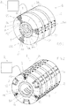
- reference numeral (1) denotes a roller conveying unit for conveying a sheet by means of aspiration, object of the present invention.
- a roller conveying unit (1) for conveying a sheet (11) by means of aspiration comprising: a roller (2) which is activatable in rotation with respect to the axis thereof, which is internally hollow and which comprises a first through-hole (3) which sets the outside of the roller (2) in fluid communication with the inside of the roller (2); a cylindrical member (40) which is arranged internally of the roller (2) and which is concentric to the roller (2).
- An annular chamber (5) being thus defined between the external surface (4a) of the cylindrical member (40) and the internal surface (2b) of the roller (2).
- the cylindrical member (40) further comprises an opening (7).
- the roller conveying unit (1) further comprises aspirating means (8) for creating a depression in the annular chamber (5) and an insert (9).
- the insert (9) is borne by the roller (2), is inserted in the first through-hole (3) of the roller (2), is dimensioned so as to contact the external surface (4a) of the cylindrical member (40) and comprises a second through-hole (10) which in turn is in communication with the outside of the roller (2) and extends through the first through-hole (3) and the annular chamber (5).
- the positions and the dimensions of the first through-hole (3) and of the opening (7) are selected in such a way that, when the roller (2) rotates with respect to the axis thereof, the insert (9) transits at the opening (7), temporarily placing the outside of the roller (2) in fluid communication with the annular chamber (5) via the second through-hole (10), so that a sheet (11) located on the outside of the roller (2) and at the first through-hole (3) is aspirated against the external surface (2a) of the roller (2) by action of the depression generated by the aspirating means (8), and is consequently conveyed (see figure 1 ).
- opening (7) is meant a removal of material at the cylindrical member (40).
- the cylindrical member (40) can be solidly filled (see figures 1 and 16 ) or hollow.
- the sheet (11) is permeable to air.
- the sheet (11) is preferably a paper sheet (11).
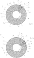
- the roller (2) is preferably cylindrical (see figures 1-2 ).
- the first through-hole (3) preferably extends in a radial direction internally of the roller (2) (see figure 3 ).
- annular chamber (5) can be cylindrical (see figures 1-2 ).
- the roller conveying unit (1) preferably comprises a frame and the cylindrical member (40) is solidly constrained to the frame.
- the aspirating means (8) can comprise an aspirating system which applies an aspiration force so that the relative pressure value internal of the annular chamber (5) is a lower value than atmospheric pressure.
- the insert (9) preferably extends in a radial direction along the first through-hole (3) (see figure 3 ).
- the second through-hole (10) preferably extends in a radial direction along the insert (9) (see figure 3 ).
- the insert (9) is preferably extractable from outside the roller (2) in order to be replaced.
- the insert (9) is advantageously insertable in the first through-hole (3) and/or extractable from the first through-hole (3) from outside the roller (2).
- replacing the two inserts with new inserts includes demounting the roller conveying unit, proceeding as follows: the roller is demounted from the frame of the roller conveying unit; the roller is separated from the cylindrical member to which the two inserts are fixed; thereafter, the two inserts are demounted from the cylindrical member by unscrewing the fastening screws.
- demounting the roller conveying unit proceeding as follows: the roller is demounted from the frame of the roller conveying unit; the roller is separated from the cylindrical member to which the two inserts are fixed; thereafter, the two inserts are demounted from the cylindrical member by unscrewing the fastening screws.
- the insert (9) is in a single body.
- the insert (9) is extractable from the first through-hole (3) using pliers or hooked tools, by use of which the insert (9) is slid along the first through-hole (3) towards the outside of the roller (2),
- the opening (7) is preferably shaped as a slit which extends along an arc of circumference of a corresponding transversal section of the cylindrical member (40) (refer to figures 1 and 2 ).
- the slit extends along the cylindrical member (40). in a circular trajectory, between two radii of the circumference delineated by the external surface (4a) of the cylindrical member (40).
- the insert (9) preferably comprises: an internal portion (12) which crosses the annular chamber (5) up to contacting the external surface (4a) of the cylindrical member (40) and which is partly inserted in the first through-hole (3); an external portion (13) which is fixed to the roller (2); elastic means (14) which are interposed between the external portion (13) and the internal portion (12) and which are compressed so as to press the internal portion (12) against the external surface (4a) of the cylindrical member (40) and for progressively lengthening as the internal portion (12) gradually wears, thus guaranteeing in any case contact of the internal portion (12) against the external surface (4a) of the cylindrical member (40).
- the elastic means (14) advantageously guarantee a greater working life of the insert (9) of the roller conveying unit (1), as the progressive lengthening of the elastic means (14) is such that the internal portion (12) fills the space created between the external surface (4a) of the cylindrical member (40) and the insert (9) following wear on the insert (9).
- a further advantage is linked to the fact that the internal portion (12) is partly inserted in the first through-hole (3) so that when the latter wears due to the dragging on the external surface (4a) of the cylindrical member (40), it is pushed by the elastic means (14) along the first through-hole (3) to guarantee contact with the external surface (4a) of the cylindrical member (40).
- the first through-hole (3) is a guide for the passing of the insert (9) internally of the first through-hole (3) along the axis thereof (see figure 3 ).
- the internal portion (12) is preferably made of a self-lubricating material.
- the internal portion (12) made of a self-lubricating material advantageously reduces friction between the insert (9) and the internal surface (2b) of the roller (2).
- the internal portion (12) can contact the external portion (13) (see figure 8 ).
- the insert (9) can comprise a volume (19) between the internal portion (12) and the external portion (13) (see figure 12 ).
- the external portion (13) can be removably fixed to the roller (2) by fastening means to protect the insert (9) with respect to the outside of the roller (2) and to delineate a portion of the external surface (2a) of the roller (2).
- fastening means can be, for example, two screws (16).
- the roller (2) comprises a pair of threaded seats (15) and the external portion (13) is fixed to the roller (2) by means of two screws (16) inserted In the pair of threaded seats (15).
- the internal portion (13) can be fixed to the external portion (12).
- the internal portion (12) can comprise a second threaded seat (17) which receives a second screw (18) which fixes the external portion (13) to the internal portion (12) of the insert (9).
- the internal portion (12) and the external portion (13) of the insert (9) are extractable from outside the roller (2) in order to be replaced.
- the insert (9) is extractable from the first through-hole (3) by initially unscrewing the second screw (18) in order to demount the external portion (13) and, subsequently, using pliers or hooked tools, by use of which the internal portion (12) is slid along the first through-hole (3) towards the outside of the roller (2).
- a part of the second through-hole (10) is fashioned in the internal portion (12) and a part of the second through-hole (10) is fashioned in the external portion (13) (see figures 1 and 3 ).
- the insert (9) can comprise a telescopic conduit (20) which is inserted in the second through-hole (10) and between at least the internal portion (12) and the external portion (13).
- the telescopic conduit (20) crosses the volume (19) and with the relative external walls, once it is inserted in the internal portion (12) is in contact with the internal portion (12) and in the external portion (13).
- the telescopic conduit (20) connects the part of the second through-hole (10) fashioned in the internal portion (12) and the part of the second through-hole (10) fashioned in the external portion (13).
- the telescopic conduit (20) tends to progressively lengthen, at the same time as the action of the elastic means (14), progressively as the internal portion (12) wears, ensuring the fluid communication between the annular chamber (5) and the outside of the roller (2).
- the telescopic conduit (20) advantageously prevents the accumulation of air in the volume (19); this accumulation might take place during the conveying of a sheet (11), following the activating of the aspirating means (8).
- the telescopic conduit (20) creates a conveying path of the depression generated by the aspirating means (8) towards the outside, thus optimising the conveying operations.
- the telescopic conduit (20) advantageously prevents the accumulation of air in the above-mentioned space.
- the elastic means (14) can form a further portion of the insert (9), can be made of an elastically deformable material and can be interposed between the external portion (13) and the internal portion (12) (see figures 1 and 9 ).
- the further portion of the insert (9), made of an elastically deformable material, can be in contact on one side with the internal portion (12) and on the other side with the external portion (13).
- a further part of the second through-hole (10) is also fashioned in the further portion of the insert.
- the insert (9) is extractable from the first through-hole (3) using pliers or hooked tools, through which the external portion (13), the elastic means (14) and the internal portion (12) are slid along the first through-hole (3) towards the outside of the roller (2).
- the elastically deformable material can be, for example, foam rubber.
- the elastic means (14) preferably comprise a spring (21) interposed between the external portion (13) and the internal portion (12).
- the internal portion (12) can comprise a housing (22) for a spring (21) which receives the spring (21) and the external portion (13) can comprise a first seat (23) for receiving regulating means for increasing or reducing the compression of the spring (21) (see figure 10 ).
- the elastic means (14) comprise a gas spring (24), interposed between the external portion (13) and the internal portion (12), which presses the internal portion (12) against the external surface (4a) of the cylindrical member (40) by means of the relative rod which progressively lengthens as the internal portion (12) gradually wears, thus guaranteeing in any case contact of the internal portion (12) against the external surface (4a) of the tubular member (40).
- the regulating means can be a regulating screw, for example.
- the insert (9) is extractable from the first through-hole (3) by first demounting the external portion (13) and then demounting the spring (21) or the gas spring (24). The extraction of the latter, since they are solidly constrained to the internal portion (12), also leads to the extraction of the internal portion (12).
- the first seat (23), which receives the regulating means can have a through-hole profile through which the regulating screw passes, for example, and in which a thread (nut screw) is made for helically coupling with the regulating screw.
- a thread nut screw
- the insert (9) preferably comprises a first plurality of through-holes (25), which first plurality of through-holes (25) comprises the second through-hole (10); and the through-holes of the first plurality of through-holes (25) are arranged adjacent to one another along an arc of circumference of the roller (2) (see figures 1 and 3 ).
- the presence of the first plurality of through-holes (25) advantageously improves the carrying out of the cutting, folding and interleaving operations during the conveying of a sheet (11).
- the first plurality of through-holes (25) comprises the second through-hole (10) and a fourth through-hole (100).
- the insert comprises a further telescopic conduit (200) which is inserted in the fourth through-hole (100).
- the telescopic conduit (20) and the further telescopic conduit (200) advantageously prevent the accumulation of air in the volume (19); this accumulation might take place during the conveying of a sheet (11) and involves the phenomenon of friction between the second through-hole (10) and the fourth through-hole (100).
- the two telescopic conduits (20, 200) create a conveying path of the depression generated by the aspirating means (8) towards the outside of the roller (2).
- the two telescopic conduits (20, 200) advantageously prevent the accumulation of air in the above-mentioned space, and therefore prevent the possibility of interference between the second through-hole (10) and the fourth through-hole (100).
- the roller (2) preferably comprises a second plurality of through-holes (26), which second plurality of through-holes (26) comprises the first through-hole (3); and wherein the through-holes of the second plurality of through-holes (26) are arranged adjacent to one another along an axis that is parallel to the axis of rotation of the roller (2) (see figures 1 and 15 ).
- the second plurality of through-holes (26) delineates a row of through-holes.
- the through-holes of the second plurality of through-holes (26) are advantageously arranged adjacent to one another along an axis parallel to the axis of rotation of the roller (2) guarantee that, during the conveying of a sheet (11), the sheet (11) itself passes from one roller conveying unit (1) to another, staying aligned to the axis of rotation of the roller (2).
- the roller conveying unit can comprise a third plurality of through-holes (261) and a fourth plurality of through-holes (262) and the through-holes of the third plurality of through-holes (261) are arranged adjacent to one another along a second axis that is parallel to the axis of rotation of the roller (2) and the through-holes of the fourth plurality of through-holes (262) are arranged adjacent to one another along a second axis that is parallel to the axis of rotation of the roller (2) (see figures 1-2 ).
- the opening (7) is an undercut (30).
- the undercut (30) can be arranged at the external surface (4a) of the cylindrical member (40).
- roller conveying unit of the present invention The following is a description of a second embodiment of the roller conveying unit of the present invention.
- the tubular member (40) is a tubular element (4) and the hollow part of the tubular element (4) defines an internal chamber (6); the aspirating means (8) are further suitable for creating a depression in the internal chamber (6); the tubular element (4) comprises a third through-hole (41) which places the annular chamber (5) in fluid communication with the internal chamber (6) (see figures 17 and 19 ).
- the aspiration force applied by the aspirating means (8) determines a relative pressure value that is lower than atmospheric pressure in the internal chamber (6) and in the annular chamber (5).
- the internal chamber (6) can be cylindrical.
- the source of depression of the aspirating means (8) applies an aspiration force so that the relative pressure value internal of the internal chamber (6) is a lower value than atmospheric pressure.
- the aspirating means (8) can be in fluid communication with the internal chamber (6).
- the cylindrical member (40) can be a tubular element (4) and the hollow part of the tubular element (4) defines an internal chamber (6).
- the aspirating means (8) are further suitable for creating a depression in the internal chamber (6); the opening (7) is a through-hole (70) which places the annular chamber (5) in fluid communication with the internal chamber (6).
- the internal chamber (6) can be cylindrical.
- the aspiration force applied by the aspirating system determines a relative pressure value that is lower than the atmospheric pressure also in the annular chamber (5).
- the dust that would tend to accumulate in the annular chamber (5) or the internal chamber (6) is advantageously aspirated externally of the roller conveying unit by action of the aspirating means (8).
- the source of depression of the aspirating means (8) applies an aspiration force so that the relative pressure value internal of the internal chamber (6) is a lower value than atmospheric pressure.
- the second through-hole (70) is shaped as a slit which extends along an arc of circumference of a corresponding transversal section of the tubular element (4), by varying the extension of the slit along the tubular element (4), in particular along the circular trajectory, also the time in which the sheet (11), at the second through-hole (10), is advantageously aspirated against the external surface (2a) of the roller (2) will vary.
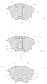
- FIG. 4-6 illustrate the second embodiment but the functioning cycle is the same for the first embodiment, for the second embodiment and for the further embodiments described herein.
- figures 4-6 illustrate an insert (9) comprising the second through-hole (10) and the fourth through-hole (100) arranged adjacent to one another along an arc of circumference of the roller (2).
- the first part (11a) of the sheet (11) will no longer be affected by the depression generated by the aspirating means (8) in the moment when the fourth through-hole (100) of the insert (9) transits at the external surface (4a) of the cylindrical member (40) ( figure 6 ).
- the second part (11b) of the sheet (11) will no longer be affected by the depression generated by the aspirating means (8) in the moment when the second through-hole (10) of the insert (9) also transits at the external surface (4a) of the cylindrical member (40).
- a roller conveyor (110) the roller conveying units (1) are arranged in a pair, one adjacent to the other, in order to carry out the cutting, folding or interleaving operations.
- Multiple paper sheets are obtained from a paper sheet (11) in reel form in input, by means of a first roller conveying unit (101), by means of blades present on the external surface (2a) of the roller (2).
- a first single sheet (11) is conveyed towards a second roller conveying unit (102).
- the first sheet (11) which is external of the roller (2) of the first roller conveying unit (101) will have to pass to the second roller conveying unit (102).
- the passage occurs in the moment when the first sheet (11) transits at an insert (9) of the second roller conveying unit (102): the first sheet (11), owing to the depression generated by the aspirating means (8) of the second roller conveying unit (102), by means of the second through-hole (10) of the insert (9) of the second roller conveying unit (102), is aspirated against the external surface (2a) of the roller (2) of the second conveying unit (102).
- a third roller conveyor unit (103) and a fourth roller conveying unit (104) operate in the same way on a second sheet (112).
- the roller conveying unit (1) for conveying a sheet (11) by means of aspiration, of the second invention of the present application comprises: a frame; a roller (2) which is activatable in rotation with respect to the axis thereof, which is internally hollow and which comprises a first through-hole (3) which sets the outside of the roller (2) in fluid communication with the inside of the roller (2); a cylindrical surface (4c) which is arranged internally of the roller (2) and which is concentric to the roller (2).
- An annular chamber (5) is thus defined between the cylindrical surface (4c) and the internal surface (2a) of the roller (2).
- the roller conveying unit (1) further comprises aspirating means (8) for creating a depression in the annular chamber (5) and an insert (9).
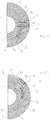
- the insert (9) is borne by the roller (2); is inserted in the first through-hole (3) of the roller (2); is dimensioned so as to contact the cylindrical surface (4c); and comprises a second through-hole (10) which in turn is in communication with the outside of the roller (2) and extends through the first through-hole (3) and the annular chamber (5): and comprises an internal portion (12) which crosses the annular chamber (5) which is partly inserted in the first through-hole (3) and which is mobile along the first through-hole (3) and across the annular chamber (5) in order to take up a first position (A), wherein it enters into contact with the cylindrical surface (4c), thus preventing fluid communication between the outside of the roller (2) and the annular chamber (5) via the second through-hole (10), or a second position (B), wherein it is detached from the cylindrical surface (4c), placing the outside of the roller (2) in fluid communication with the annular chamber (5) via the second through-hole (10).
- A first position
- B second position
- the roller conveying unit (1) further comprises: a cam (27) which is solidly constrained to the frame; a cam follower (31) which is borne by the roller (2) and which engages with the cam (27) and which commands the movement of the internal portion (12) of the insert (9): wherein the cam (27) is configured in such a way that, when the roller (2) rotates with respect to the axis thereof, the cam follower (31) runs on the cam (27) and thus moves the internal portion (12) of the insert (9) between the first position (A) and the second position (B), so that a sheet (11) located on the outside of the roller (2) and at the first through-hole (3) is aspirated against the external surface (2a) of the roller (2) by action of the depression generated by the aspirating means (8), and is consequently conveyed.
- a cam (27) which is solidly constrained to the frame
- a cam follower (31) which is borne by the roller (2) and which engages with the cam (27) and which commands the movement of the internal portion (12) of the insert (9):
- the cam follower (31) is connected to the internal portion of the insert and comprises an abutting element (29) which, during the rotation of the roller (2), slides on the cam (27), so as to move the internal portion (12) between the first position (A) (see figure 13 ) and the second position (B) (see figure 14 ).
- the above-mentioned roller conveying unit (1) preferably comprises elastic means (not illustrated) which are interposed between the cam follower (31) and the internal portion (12) and which are compressed so as to press the internal portion (12) against the cylindrical surface (4c) and for progressively lengthening as the internal portion (12) gradually wears, thus guaranteeing in any case contact of the internal portion (12) against the cylindrical surface (4c).
- the elastic means (14) advantageously guarantee a longer working life of the insert (9) of the roller conveying unit (1), as the progressive lengthening of the elastic means (14) is such that the internal portion (12) fills the space created between the internal portion (12) and the cylindrical surface (4c), following wear on the internal portion (12).
Landscapes
- Engineering & Computer Science (AREA)
- Mechanical Engineering (AREA)
- Delivering By Means Of Belts And Rollers (AREA)
Claims (14)
- Rollenfördereinheit (1) zum Fördern eines Bogens (11) durch Saugwirkung, umfassend:eine Rolle (2), die um ihre Achse in Drehbewegung versetzt werden kann, die innen hohl ist und die ein erstes Durchgangsloch (3) umfasst, das die Außenseite der Rolle (2) in Fluidverbindung mit der Innenseite der Rolle (2) setzt;ein zylindrisches Organ (40), das innerhalb der Rolle (2) angeordnet ist und das konzentrisch zu der Rolle (2) ist, wodurch eine ringförmige Kammer (5) zwischen der Außenoberfläche (4a) des zylindrischen Organs (40) und der Innenoberfläche (2b) der Rolle (2) gebildet wird;wobei das zylindrische Organ (40) ferner eine Öffnung (7) umfasst;Saugmittel (8) zum Erzeugen eines Unterdrucks in der ringförmigen Kammer (5);einen Einsatz (9);dadurch gekennzeichnet, dass der Einsatz (9) von der Rolle (2) getragen wird, in das erste Durchgangsloch (3) der Rolle (2) eingesetzt ist, derart bemessen ist, dass er die Außenoberfläche (4a) des zylindrischen Organs (40) berührt, und ein zweites Durchgangsloch (10) umfasst, das wiederum in Verbindung mit der Außenseite der Rolle (2) ist und das sich durch das erste Durchgangsloch (3) und die ringförmige Kammer (5) hindurch erstreckt;wobei die Positionen und die Abmessungen des ersten Durchgangslochs (3) und der Öffnung (7) so gewählt sind, dass, wenn sich die Rolle (2) um ihre Achse dreht, der Einsatz (9) durch die Öffnung (7) hindurchtritt und somit die Außenseite der Rolle (2) vorübergehend über das zweite Durchgangsloch (10) in Fluidverbindung mit der ringförmigen Kammer (5) setzt, so dass ein Bogen (11), der auf der Außenseite der Rolle (2) und an dem ersten Durchgangsloch (3) angeordnet ist, durch die von den Saugmitteln (8) erzeugte Unterdruckwirkung gegen die Außenoberfläche (2a) der Rolle (2) angesaugt wird und infolgedessen befördert wird.
- Rollenfördereinheit (1) nach dem vorhergehenden Anspruch, wobei die Öffnung (7) eine Hinterschneidung (30) ist.
- Rollenfördereinheit (1) nach dem vorhergehenden Anspruch, wobei: das zylindrische Organ (40) ein röhrenförmiges Element (4) ist und der hohle Teil des röhrenförmigen Elements (4) eine innere Kammer (6) bildet; die Saugmittel (8) ferner geeignet sind, einen Unterdruck in der inneren Kammer (6) zu erzeugen; das röhrenförmige Element (4) ein drittes Durchgangsloch (41) umfasst, das die ringförmige Kammer (5) in Fluidverbindung mit der inneren Kammer (6) setzt.
- Rollenfördereinheit (1) nach Anspruch 1, wobei: das zylindrische Organ (40) ein röhrenförmiges Element (4) ist und der hohle Teil des röhrenförmigen Elements (4) eine innere Kammer (6) bildet; die Saugmittel (8) ferner geeignet sind, einen Unterdruck in der inneren Kammer (6) zu erzeugen; die Öffnung (7) ein Durchgangsloch (70) ist, das die ringförmige Kammer (5) in Fluidverbindung mit der inneren Kammer (6) setzt.
- Rollenfördereinheit (1) nach einem der vorhergehenden Ansprüche, wobei der Einsatz (9) von außerhalb der Rolle (2) herausziehbar ist, um ersetzt werden zu können.
- Rollenfördereinheit (1) nach einem der vorhergehenden Ansprüche, wobei die Öffnung (7) in Form eines Schlitzes ausgeführt ist, der sich entlang eines Kreisbogens eines entsprechenden Querschnitts des zylindrischen Organs (40) erstreckt.
- Rollenfördereinheit (1) nach einem der vorhergehenden Ansprüche, wobei der Einsatz (9) umfasst: einen inneren Abschnitt (12), der die ringförmige Kammer (5) bis zum Kontakt mit der Außenoberfläche (4a) des zylindrischen Organs (40) durchquert und der teilweise in das erste Durchgangsloch (3) eingeführt ist; einen äußeren Abschnitt (13), der an der Rolle (2) befestigt ist; elastische Mittel (14) die zwischen dem äußeren Abschnitt (13) und dem inneren Abschnitt (12) angeordnet sind und die derart komprimiert werden, dass sie den inneren Abschnitt (12) gegen die Außenoberfläche (4a) des zylindrischen Organs (40) drücken und dass sie sich, mit der allmählichen Abnutzung des inneren Abschnitts (12), nach und nach verlängern, um somit in jedem Fall den Kontakt des inneren Abschnitts (12) gegen die Außenoberfläche (4a) des zylindrischen Organs (40) zu gewährleisten.
- Rollenfördereinheit (1) nach dem vorhergehenden Anspruch, wobei der Einsatz (9) einen teleskopartigen Kanal (20) umfasst und wobei der teleskopartige Kanal (20) in das zweite Durchgangsloch (10) und zwischen zumindest dem inneren Abschnitt (12) und dem äußeren Abschnitt (13) eingeführt ist.
- Rollenfördereinheit (1) nach Anspruch 7, wobei die elastischen Mittel (14) einen weiteren Abschnitt des Einsatzes (9) bilden, aus einem elastisch verformbaren Material bestehen und zwischen dem äußeren Abschnitt (13) und dem inneren Abschnitt (12) angeordnet sind.
- Rollenfördereinheit (1) nach Anspruch 7, wobei die elastischen Mittel (14) eine Feder (21) umfassen, die zwischen dem äußeren Abschnitt (13) und dem inneren Abschnitt (12) angeordnet ist; wobei der innere Abschnitt (12) ein Gehäuse (22) für eine Feder (21) umfasst, das die Feder (21) aufnimmt, und wobei der äußere Abschnitt (13) einen ersten Sitz (23) zur Aufnahme von Regulierungsmitteln zum Erhöhen oder Verringern der Kompression der Feder (21) umfasst.
- Rollenfördereinheit (1) nach einem der vorhergehenden Ansprüche, wobei der Einsatz (9) eine erste Vielzahl von Durchgangslöchern (25) umfasst, und diese erste Vielzahl von Durchgangslöchern (25) das zweite Durchgangsloch (10) beinhaltet; und wobei die Durchgangslöcher der ersten Vielzahl von Durchgangslöchern (25) nebeneinander entlang eines Kreisbogens der Rolle (2) angeordnet sind.
- Rollenfördereinheit (1) nach einem der vorhergehenden Ansprüche, wobei die Rolle (2) eine zweite Vielzahl von Durchgangslöchern (26) umfasst, und diese zweite Vielzahl von Durchgangslöchern (26) das erste Durchgangsloch (3) beinhaltet; und wobei die Durchgangslöcher der zweiten Vielzahl von Durchgangslöchern (26) nebeneinander entlang einer zur Drehachse der Rolle (2) parallelen Richtung angeordnet sind.
- Rollenfördereinheit (1) zum Fördern eines Bogens (11) durch Saugwirkung, umfassend:einen Rahmen;eine Rolle (2), die um ihre Achse in Drehbewegung versetzt werden kann, die innen hohl ist und die ein erstes Durchgangsloch (3) umfasst, das die Außenseite der Rolle (2) in Fluidverbindung mit der Innenseite der Rolle (2) setzt;eine zylindrische Oberfläche (4c), die innerhalb der Rolle (2) angeordnet ist und die konzentrisch zu der Rolle (2) ist;eine ringförmige Kammer (5), die dadurch zwischen der zylindrischen Oberfläche (4c) und der Innenoberfläche (2b) der Rolle (2) gebildet wird; Saugmittel (8) zum Erzeugen eines Unterdrucks in der ringförmigen Kammer (5);einen Einsatz (9);dadurch gekennzeichnet, dass der Einsatz (9): von der Rolle (2) getragen wird; in das erste Durchgangsloch (3) der Rolle (2) eingesetzt ist; derart bemessen ist, dass er die zylindrische Oberfläche (4c) berührt; und ein zweites Durchgangsloch (10) umfasst, das wiederum in Verbindung mit der Außenseite der Rolle (2) ist und das sich durch das erste Durchgangsloch (3) und die ringförmige Kammer (5) hindurch erstreckt; und einen inneren Abschnitt (12) umfasst, der die ringförmige Kammer (5) durchquert, der teilweise in das erste Durchgangsloch (3) eingeführt ist und der entlang des ersten Durchgangslochs (3) und durch die ringförmige Kammer (5) beweglich ist, um eine erste Position (A) einzunehmen, in der er in Kontakt mit der zylindrischen Oberfläche (4c) ist, um somit die Fluidverbindung zwischen der Außenseite der Rolle (2) und der ringförmigen Kammer (5) über das zweite Durchgangsloch (10) zu verhindern, oder eine zweite Position (B) einzunehmen, in der er von der zylindrischen Oberfläche (4c) abgehoben ist, um somit die Außenseite der Rolle (2) über das zweite Durchgangsloch (10) in Fluidverbindung mit der ringförmigen Kammer (5) zu setzen;und dadurch, dass die Rollenfördereinheit (1) umfasst:eine Kurvenscheibe (27), die fest mit dem Rahmen verbunden ist;einen Abtaster (31), der von der Rolle (2) getragen wird und der mit der Kurvenscheibe (27) in Eingriff gelangt und der die Bewegung des inneren Abschnitts (12) des Einsatzes (9) steuert;wobei die Kurvenscheibe (27) derart konfiguriert ist, dass, wenn sich die Rolle (2) um ihre Achse dreht, der Abtaster (31) auf der Kurvenscheibe (27) läuft und somit den inneren Abschnitt (12) des Einsatzes (9) zwischen der ersten Position (A) und der zweiten Position (B) bewegt, so dass ein Bogen (11), der auf der Außenseite der Rolle (2) und an dem ersten Durchgangsloch (3) angeordnet ist, durch die von den Saugmitteln (8) erzeugte Unterdruckwirkung gegen die Außenoberfläche (2a) der Rolle (2) gesaugt und infolgedessen befördert wird.
- Rollenfördereinheit (1) nach dem vorhergehenden Anspruch, umfassend elastische Mittel, die zwischen dem Abtaster (31) und dem inneren Abschnitt (12) des Einsatzes (9) angeordnet sind und die derart komprimiert werden, dass sie den inneren Abschnitt (12) gegen die zylindrische Oberfläche (4c) drücken und dass sie sich, mit der allmählichen Abnutzung des inneren Abschnitts (12), nach und nach verlängern, um somit in jedem Fall den Kontakt des inneren Abschnitts (12) gegen die zylindrische Oberfläche (4c) zu gewährleisten.
Priority Applications (2)
| Application Number | Priority Date | Filing Date | Title |
|---|---|---|---|
| RS20211025A RS62229B1 (sr) | 2017-12-15 | 2018-12-11 | Transportna jedinica sa valjkom za transport lista usisavanjem |
| PL18833521T PL3724112T3 (pl) | 2017-12-15 | 2018-12-11 | Jednostka przenośnika wałkowego do przenoszenia arkusza za pomocą zasysania |
Applications Claiming Priority (3)
| Application Number | Priority Date | Filing Date | Title |
|---|---|---|---|
| IT201700144895 | 2017-12-15 | ||
| IT201800005619 | 2018-05-23 | ||
| PCT/IB2018/059862 WO2019116216A1 (en) | 2017-12-15 | 2018-12-11 | A roller conveying unit for conveying a sheet by means of aspiration |
Publications (2)
| Publication Number | Publication Date |
|---|---|
| EP3724112A1 EP3724112A1 (de) | 2020-10-21 |
| EP3724112B1 true EP3724112B1 (de) | 2021-05-26 |
Family
ID=65013744
Family Applications (1)
| Application Number | Title | Priority Date | Filing Date |
|---|---|---|---|
| EP18833521.0A Active EP3724112B1 (de) | 2017-12-15 | 2018-12-11 | Saugrollenfördereinheit zum fördern von bögen durch eine saugwirkung |
Country Status (8)
| Country | Link |
|---|---|
| US (1) | US11078037B2 (de) |
| EP (1) | EP3724112B1 (de) |
| CN (1) | CN111566030B (de) |
| BR (1) | BR112020012041B1 (de) |
| ES (1) | ES2881715T3 (de) |
| PL (1) | PL3724112T3 (de) |
| RS (1) | RS62229B1 (de) |
| WO (1) | WO2019116216A1 (de) |
Cited By (7)
| Publication number | Priority date | Publication date | Assignee | Title |
|---|---|---|---|---|
| IT202300017328A1 (it) | 2023-08-17 | 2023-11-17 | Ot Lucca S R L | Macchina e metodo per produrre pile di tovaglioli e pila di tovaglioli |
| IT202300024255A1 (it) | 2023-11-16 | 2024-02-16 | Ot Lucca S R L | Pacco di fogli interfogliati e metodo e macchina interfogliatrice per produrli |
| EP4192773B1 (de) | 2020-11-20 | 2024-10-16 | Valmet Tissue Converting S.r.l. | Saugwalze einer papier- oder papierbahn in einer papierverarbeitungsmaschine |
| IT202300016308A1 (it) * | 2023-08-01 | 2025-02-01 | Valmet Tissue Converting S R L | Rullo di aspirazione di un prodotto laminare |
| WO2025027512A1 (en) * | 2023-08-01 | 2025-02-06 | Valmet Tissue Converting S.R.L. | Suction roll of a laminar product |
| WO2025027514A1 (en) * | 2023-08-01 | 2025-02-06 | Valmet Tissue Converting S.R.L. | Suction roll of a laminar product |
| WO2025027516A1 (en) * | 2023-08-01 | 2025-02-06 | Valmet Tissue Converting S.R.L. | Suction roll of a laminar product |
Family Cites Families (23)
| Publication number | Priority date | Publication date | Assignee | Title |
|---|---|---|---|---|
| DK112101B (da) * | 1967-06-12 | 1968-11-11 | J Carstens | Apparat til fremføring af ark. |
| AT353221B (de) * | 1973-11-21 | 1979-11-12 | Gao Ges Automation Org | Vorrichtung zum vereinzeln von papierboegen u. dgl. |
| DE2905278C3 (de) * | 1979-02-12 | 1981-11-26 | GAO Gesellschaft für Automation und Organisation mbH, 8000 München | Vorrichtung zum Vereinzeln von flachen Fördergut mit einer Saugtrommel |
| DE3068657D1 (en) * | 1979-04-20 | 1984-08-30 | Tokyo Shibaura Electric Co | Sheet transport apparatus |
| DE3938480A1 (de) * | 1989-11-20 | 1991-05-23 | Hell Rudolf Dr Ing Gmbh | Vorrichtung zum aufspannen von blattfoermigem aufzeichnungsmaterial |
| US5149554A (en) * | 1991-04-24 | 1992-09-22 | Oscar Mayer Foods Corporation | Method and apparatus for transferring food material slices |
| DE4315549C2 (de) * | 1993-05-10 | 2003-11-20 | Heidelberger Druckmasch Ag | Einrichtung zur Saugluftsteuerung für eine Bogenübergabetrommel |
| DE19854844A1 (de) * | 1997-12-24 | 1999-07-01 | Heidelberger Druckmasch Ag | Vorrichtung zur Saugluftsteuerung |
| US6550388B2 (en) * | 2000-12-06 | 2003-04-22 | Creo Products Inc. | Apparatus and method for removing a thin deformable sheet |
| ITMI20011800A1 (it) * | 2001-08-17 | 2003-02-17 | Studio Design S A S Di Stefano | Macchina per la produzione di materiale flessibile in fogli |
| US11230453B2 (en) * | 2003-02-18 | 2022-01-25 | Körber Tissue Fold S.R.L. | Roller for conveying a web or sheet of paper in paper converting machines and conveying method thus obtained |
| EP1449799A1 (de) * | 2003-02-18 | 2004-08-25 | M T C - Macchine Trasformazione Carta S.r.l. | Walze zum Fördern einer Papierbahn oder eines Papierblattes in einer Papierverarbeitungsmaschine und dabei erzieltes Transportverfahren |
| JP4638165B2 (ja) * | 2003-07-16 | 2011-02-23 | ハイデルベルガー ドルツクマシーネン アクチエンゲゼルシヤフト | 枚葉紙を処理する機械 |
| US9944487B2 (en) * | 2007-02-21 | 2018-04-17 | Curt G. Joa, Inc. | Single transfer insert placement method and apparatus |
| JP2010111478A (ja) * | 2008-11-06 | 2010-05-20 | Toyota Motor Corp | ガイドローラ |
| JP5838024B2 (ja) * | 2010-08-30 | 2015-12-24 | ユニ・チャーム株式会社 | 吸収性物品に係る連続シートの複合体の製造方法、製造装置、及び吸収性物品の製造方法 |
| US8852068B2 (en) * | 2011-04-21 | 2014-10-07 | C.G. Bretting Manufacturing Co., Inc. | Tube in a tube mechanical folding roll |
| CN102431833B (zh) * | 2011-10-28 | 2014-08-20 | 佛山市南海区德昌誉机械制造有限公司 | 一种用于折叠连续片材的折叠机用折叠辊 |
| DE102014001969B4 (de) * | 2013-03-11 | 2022-03-24 | Heidelberger Druckmaschinen Ag | Formatumstellung einer Pneumatiktrommel |
| US8939445B2 (en) * | 2013-05-30 | 2015-01-27 | Kimberly-Clark Worldwide, Inc. | Vacuum roll with internal rotary valve |
| CN203612722U (zh) * | 2013-11-08 | 2014-05-28 | 株式会社瑞光 | 搬运装置 |
| US9862112B2 (en) * | 2015-05-21 | 2018-01-09 | Curt G. Joa, Inc. | Systems and methods for cutting or perforating a web material |
| CN205953181U (zh) * | 2016-03-30 | 2017-02-15 | 法比奥·泼尼股份公司 | 用于幅材处理机的吸辊和包括所述吸辊的交叉折叠机 |
-
2018
- 2018-12-11 EP EP18833521.0A patent/EP3724112B1/de active Active
- 2018-12-11 PL PL18833521T patent/PL3724112T3/pl unknown
- 2018-12-11 US US16/771,083 patent/US11078037B2/en active Active
- 2018-12-11 RS RS20211025A patent/RS62229B1/sr unknown
- 2018-12-11 WO PCT/IB2018/059862 patent/WO2019116216A1/en not_active Ceased
- 2018-12-11 CN CN201880085995.2A patent/CN111566030B/zh active Active
- 2018-12-11 ES ES18833521T patent/ES2881715T3/es active Active
- 2018-12-11 BR BR112020012041-3A patent/BR112020012041B1/pt active IP Right Grant
Cited By (8)
| Publication number | Priority date | Publication date | Assignee | Title |
|---|---|---|---|---|
| EP4192773B1 (de) | 2020-11-20 | 2024-10-16 | Valmet Tissue Converting S.r.l. | Saugwalze einer papier- oder papierbahn in einer papierverarbeitungsmaschine |
| IT202300016308A1 (it) * | 2023-08-01 | 2025-02-01 | Valmet Tissue Converting S R L | Rullo di aspirazione di un prodotto laminare |
| WO2025027512A1 (en) * | 2023-08-01 | 2025-02-06 | Valmet Tissue Converting S.R.L. | Suction roll of a laminar product |
| WO2025027514A1 (en) * | 2023-08-01 | 2025-02-06 | Valmet Tissue Converting S.R.L. | Suction roll of a laminar product |
| WO2025027516A1 (en) * | 2023-08-01 | 2025-02-06 | Valmet Tissue Converting S.R.L. | Suction roll of a laminar product |
| WO2025027513A1 (en) * | 2023-08-01 | 2025-02-06 | Valmet Tissue Converting S.R.L. | Suction roll of a laminar product |
| IT202300017328A1 (it) | 2023-08-17 | 2023-11-17 | Ot Lucca S R L | Macchina e metodo per produrre pile di tovaglioli e pila di tovaglioli |
| IT202300024255A1 (it) | 2023-11-16 | 2024-02-16 | Ot Lucca S R L | Pacco di fogli interfogliati e metodo e macchina interfogliatrice per produrli |
Also Published As
| Publication number | Publication date |
|---|---|
| ES2881715T3 (es) | 2021-11-30 |
| BR112020012041A2 (pt) | 2020-11-24 |
| US11078037B2 (en) | 2021-08-03 |
| WO2019116216A1 (en) | 2019-06-20 |
| CN111566030A (zh) | 2020-08-21 |
| BR112020012041B1 (pt) | 2024-02-06 |
| RS62229B1 (sr) | 2021-09-30 |
| US20210078815A1 (en) | 2021-03-18 |
| CN111566030B (zh) | 2021-07-27 |
| EP3724112A1 (de) | 2020-10-21 |
| PL3724112T3 (pl) | 2021-11-29 |
Similar Documents
| Publication | Publication Date | Title |
|---|---|---|
| EP3724112B1 (de) | Saugrollenfördereinheit zum fördern von bögen durch eine saugwirkung | |
| CN107583334B (zh) | 过滤装置、清洁单元、波纹管汽缸及其用途 | |
| EP2531330B1 (de) | Rotierende arbeitsvorrichtung | |
| KR101129051B1 (ko) | 접착 테이프 원단필름 절단 조립체, 접착 테이프 원단필름 절단 장치 및 이를 사용하여 절취부가 형성된 접착 테이프를 제조하는 방법 | |
| EP2844476A2 (de) | Zwischenhülsen mit diametral expandierbaren stabilisatoren | |
| KR20170108127A (ko) | 스테이터/로터 시스템, 그리고 스테이터/로터 시스템 내에서 스테이터 조정 방법 | |
| FI105084B (fi) | Muovipellettien annostelujärjestelmä | |
| US9446462B2 (en) | Material cutter clamping collet | |
| EP3433033B1 (de) | Förderer mit automatischem reinigungssystem für klebstoffverteiler | |
| EP1394295B1 (de) | Verfahren und Vorrichtung zum Schneiden von Fasern in Stücke | |
| CN106900822B (zh) | 肠衣制动组件 | |
| EP3241444B1 (de) | Darmbremsenanordnung mit beweglichen sicherheitsmitteln | |
| WO2014179522A9 (en) | Cutting apparatus for fibers and method of cutting | |
| EP2781159B1 (de) | Darmbremse mit rotierenden Bremselementen | |
| US9956699B2 (en) | Cutting apparatuses | |
| JP5800627B2 (ja) | 重送防止用部材脱着機構、及び重送防止用部材の脱着方法 | |
| CN220484469U (zh) | 一种不锈钢带导向装置 | |
| CN102275760A (zh) | 凹印机生产线分切辊纸张压平装置 | |
| WO2023007469A1 (en) | Tolerance adjuster and wear device for sortation system | |
| US20180016748A1 (en) | Lubricant Applicator and Method for Lubricating a Backing Drum and Apparatus |
Legal Events
| Date | Code | Title | Description |
|---|---|---|---|
| STAA | Information on the status of an ep patent application or granted ep patent |
Free format text: STATUS: UNKNOWN |
|
| STAA | Information on the status of an ep patent application or granted ep patent |
Free format text: STATUS: THE INTERNATIONAL PUBLICATION HAS BEEN MADE |
|
| PUAI | Public reference made under article 153(3) epc to a published international application that has entered the european phase |
Free format text: ORIGINAL CODE: 0009012 |
|
| STAA | Information on the status of an ep patent application or granted ep patent |
Free format text: STATUS: REQUEST FOR EXAMINATION WAS MADE |
|
| 17P | Request for examination filed |
Effective date: 20200703 |
|
| AK | Designated contracting states |
Kind code of ref document: A1 Designated state(s): AL AT BE BG CH CY CZ DE DK EE ES FI FR GB GR HR HU IE IS IT LI LT LU LV MC MK MT NL NO PL PT RO RS SE SI SK SM TR |
|
| AX | Request for extension of the european patent |
Extension state: BA ME |
|
| GRAP | Despatch of communication of intention to grant a patent |
Free format text: ORIGINAL CODE: EPIDOSNIGR1 |
|
| STAA | Information on the status of an ep patent application or granted ep patent |
Free format text: STATUS: GRANT OF PATENT IS INTENDED |
|
| RIC1 | Information provided on ipc code assigned before grant |
Ipc: B65H 5/22 20060101AFI20201130BHEP Ipc: B65H 45/24 20060101ALI20201130BHEP Ipc: B65H 45/28 20060101ALI20201130BHEP Ipc: B65H 27/00 20060101ALI20201130BHEP |
|
| DAV | Request for validation of the european patent (deleted) | ||
| DAX | Request for extension of the european patent (deleted) | ||
| INTG | Intention to grant announced |
Effective date: 20201218 |
|
| GRAS | Grant fee paid |
Free format text: ORIGINAL CODE: EPIDOSNIGR3 |
|
| GRAA | (expected) grant |
Free format text: ORIGINAL CODE: 0009210 |
|
| STAA | Information on the status of an ep patent application or granted ep patent |
Free format text: STATUS: THE PATENT HAS BEEN GRANTED |
|
| AK | Designated contracting states |
Kind code of ref document: B1 Designated state(s): AL AT BE BG CH CY CZ DE DK EE ES FI FR GB GR HR HU IE IS IT LI LT LU LV MC MK MT NL NO PL PT RO RS SE SI SK SM TR |
|
| REG | Reference to a national code |
Ref country code: GB Ref legal event code: FG4D |
|
| REG | Reference to a national code |
Ref country code: CH Ref legal event code: EP |
|
| REG | Reference to a national code |
Ref country code: AT Ref legal event code: REF Ref document number: 1396043 Country of ref document: AT Kind code of ref document: T Effective date: 20210615 |
|
| REG | Reference to a national code |
Ref country code: DE Ref legal event code: R096 Ref document number: 602018017820 Country of ref document: DE |
|
| REG | Reference to a national code |
Ref country code: IE Ref legal event code: FG4D |
|
| REG | Reference to a national code |
Ref country code: RO Ref legal event code: EPE |
|
| REG | Reference to a national code |
Ref country code: LT Ref legal event code: MG9D |
|
| REG | Reference to a national code |
Ref country code: AT Ref legal event code: MK05 Ref document number: 1396043 Country of ref document: AT Kind code of ref document: T Effective date: 20210526 |
|
| PG25 | Lapsed in a contracting state [announced via postgrant information from national office to epo] |
Ref country code: AT Free format text: LAPSE BECAUSE OF FAILURE TO SUBMIT A TRANSLATION OF THE DESCRIPTION OR TO PAY THE FEE WITHIN THE PRESCRIBED TIME-LIMIT Effective date: 20210526 Ref country code: BG Free format text: LAPSE BECAUSE OF FAILURE TO SUBMIT A TRANSLATION OF THE DESCRIPTION OR TO PAY THE FEE WITHIN THE PRESCRIBED TIME-LIMIT Effective date: 20210826 Ref country code: FI Free format text: LAPSE BECAUSE OF FAILURE TO SUBMIT A TRANSLATION OF THE DESCRIPTION OR TO PAY THE FEE WITHIN THE PRESCRIBED TIME-LIMIT Effective date: 20210526 Ref country code: LT Free format text: LAPSE BECAUSE OF FAILURE TO SUBMIT A TRANSLATION OF THE DESCRIPTION OR TO PAY THE FEE WITHIN THE PRESCRIBED TIME-LIMIT Effective date: 20210526 Ref country code: HR Free format text: LAPSE BECAUSE OF FAILURE TO SUBMIT A TRANSLATION OF THE DESCRIPTION OR TO PAY THE FEE WITHIN THE PRESCRIBED TIME-LIMIT Effective date: 20210526 |
|
| REG | Reference to a national code |
Ref country code: NL Ref legal event code: MP Effective date: 20210526 |
|
| PG25 | Lapsed in a contracting state [announced via postgrant information from national office to epo] |
Ref country code: GR Free format text: LAPSE BECAUSE OF FAILURE TO SUBMIT A TRANSLATION OF THE DESCRIPTION OR TO PAY THE FEE WITHIN THE PRESCRIBED TIME-LIMIT Effective date: 20210827 Ref country code: IS Free format text: LAPSE BECAUSE OF FAILURE TO SUBMIT A TRANSLATION OF THE DESCRIPTION OR TO PAY THE FEE WITHIN THE PRESCRIBED TIME-LIMIT Effective date: 20210926 Ref country code: LV Free format text: LAPSE BECAUSE OF FAILURE TO SUBMIT A TRANSLATION OF THE DESCRIPTION OR TO PAY THE FEE WITHIN THE PRESCRIBED TIME-LIMIT Effective date: 20210526 Ref country code: NO Free format text: LAPSE BECAUSE OF FAILURE TO SUBMIT A TRANSLATION OF THE DESCRIPTION OR TO PAY THE FEE WITHIN THE PRESCRIBED TIME-LIMIT Effective date: 20210826 Ref country code: SE Free format text: LAPSE BECAUSE OF FAILURE TO SUBMIT A TRANSLATION OF THE DESCRIPTION OR TO PAY THE FEE WITHIN THE PRESCRIBED TIME-LIMIT Effective date: 20210526 Ref country code: PT Free format text: LAPSE BECAUSE OF FAILURE TO SUBMIT A TRANSLATION OF THE DESCRIPTION OR TO PAY THE FEE WITHIN THE PRESCRIBED TIME-LIMIT Effective date: 20210927 |
|
| REG | Reference to a national code |
Ref country code: ES Ref legal event code: FG2A Ref document number: 2881715 Country of ref document: ES Kind code of ref document: T3 Effective date: 20211130 |
|
| PG25 | Lapsed in a contracting state [announced via postgrant information from national office to epo] |
Ref country code: NL Free format text: LAPSE BECAUSE OF FAILURE TO SUBMIT A TRANSLATION OF THE DESCRIPTION OR TO PAY THE FEE WITHIN THE PRESCRIBED TIME-LIMIT Effective date: 20210526 |
|
| PG25 | Lapsed in a contracting state [announced via postgrant information from national office to epo] |
Ref country code: DK Free format text: LAPSE BECAUSE OF FAILURE TO SUBMIT A TRANSLATION OF THE DESCRIPTION OR TO PAY THE FEE WITHIN THE PRESCRIBED TIME-LIMIT Effective date: 20210526 Ref country code: CZ Free format text: LAPSE BECAUSE OF FAILURE TO SUBMIT A TRANSLATION OF THE DESCRIPTION OR TO PAY THE FEE WITHIN THE PRESCRIBED TIME-LIMIT Effective date: 20210526 Ref country code: SM Free format text: LAPSE BECAUSE OF FAILURE TO SUBMIT A TRANSLATION OF THE DESCRIPTION OR TO PAY THE FEE WITHIN THE PRESCRIBED TIME-LIMIT Effective date: 20210526 Ref country code: SK Free format text: LAPSE BECAUSE OF FAILURE TO SUBMIT A TRANSLATION OF THE DESCRIPTION OR TO PAY THE FEE WITHIN THE PRESCRIBED TIME-LIMIT Effective date: 20210526 Ref country code: EE Free format text: LAPSE BECAUSE OF FAILURE TO SUBMIT A TRANSLATION OF THE DESCRIPTION OR TO PAY THE FEE WITHIN THE PRESCRIBED TIME-LIMIT Effective date: 20210526 |
|
| REG | Reference to a national code |
Ref country code: DE Ref legal event code: R097 Ref document number: 602018017820 Country of ref document: DE |
|
| PLBE | No opposition filed within time limit |
Free format text: ORIGINAL CODE: 0009261 |
|
| STAA | Information on the status of an ep patent application or granted ep patent |
Free format text: STATUS: NO OPPOSITION FILED WITHIN TIME LIMIT |
|
| 26N | No opposition filed |
Effective date: 20220301 |
|
| PG25 | Lapsed in a contracting state [announced via postgrant information from national office to epo] |
Ref country code: IS Free format text: LAPSE BECAUSE OF FAILURE TO SUBMIT A TRANSLATION OF THE DESCRIPTION OR TO PAY THE FEE WITHIN THE PRESCRIBED TIME-LIMIT Effective date: 20210926 Ref country code: AL Free format text: LAPSE BECAUSE OF FAILURE TO SUBMIT A TRANSLATION OF THE DESCRIPTION OR TO PAY THE FEE WITHIN THE PRESCRIBED TIME-LIMIT Effective date: 20210526 |
|
| PG25 | Lapsed in a contracting state [announced via postgrant information from national office to epo] |
Ref country code: MC Free format text: LAPSE BECAUSE OF FAILURE TO SUBMIT A TRANSLATION OF THE DESCRIPTION OR TO PAY THE FEE WITHIN THE PRESCRIBED TIME-LIMIT Effective date: 20210526 |
|
| REG | Reference to a national code |
Ref country code: CH Ref legal event code: PL |
|
| REG | Reference to a national code |
Ref country code: BE Ref legal event code: MM Effective date: 20211231 |
|
| PG25 | Lapsed in a contracting state [announced via postgrant information from national office to epo] |
Ref country code: LU Free format text: LAPSE BECAUSE OF NON-PAYMENT OF DUE FEES Effective date: 20211211 Ref country code: IE Free format text: LAPSE BECAUSE OF NON-PAYMENT OF DUE FEES Effective date: 20211211 |
|
| PG25 | Lapsed in a contracting state [announced via postgrant information from national office to epo] |
Ref country code: FR Free format text: LAPSE BECAUSE OF NON-PAYMENT OF DUE FEES Effective date: 20211231 Ref country code: BE Free format text: LAPSE BECAUSE OF NON-PAYMENT OF DUE FEES Effective date: 20211231 |
|
| PG25 | Lapsed in a contracting state [announced via postgrant information from national office to epo] |
Ref country code: LI Free format text: LAPSE BECAUSE OF NON-PAYMENT OF DUE FEES Effective date: 20211231 Ref country code: CH Free format text: LAPSE BECAUSE OF NON-PAYMENT OF DUE FEES Effective date: 20211231 |
|
| P01 | Opt-out of the competence of the unified patent court (upc) registered |
Effective date: 20230317 |
|
| PG25 | Lapsed in a contracting state [announced via postgrant information from national office to epo] |
Ref country code: CY Free format text: LAPSE BECAUSE OF FAILURE TO SUBMIT A TRANSLATION OF THE DESCRIPTION OR TO PAY THE FEE WITHIN THE PRESCRIBED TIME-LIMIT Effective date: 20210526 |
|
| PG25 | Lapsed in a contracting state [announced via postgrant information from national office to epo] |
Ref country code: HU Free format text: LAPSE BECAUSE OF FAILURE TO SUBMIT A TRANSLATION OF THE DESCRIPTION OR TO PAY THE FEE WITHIN THE PRESCRIBED TIME-LIMIT; INVALID AB INITIO Effective date: 20181211 |
|
| PG25 | Lapsed in a contracting state [announced via postgrant information from national office to epo] |
Ref country code: MK Free format text: LAPSE BECAUSE OF FAILURE TO SUBMIT A TRANSLATION OF THE DESCRIPTION OR TO PAY THE FEE WITHIN THE PRESCRIBED TIME-LIMIT Effective date: 20210526 |
|
| PG25 | Lapsed in a contracting state [announced via postgrant information from national office to epo] |
Ref country code: MT Free format text: LAPSE BECAUSE OF FAILURE TO SUBMIT A TRANSLATION OF THE DESCRIPTION OR TO PAY THE FEE WITHIN THE PRESCRIBED TIME-LIMIT Effective date: 20210526 |
|
| PGFP | Annual fee paid to national office [announced via postgrant information from national office to epo] |
Ref country code: DE Payment date: 20250113 Year of fee payment: 7 |
|
| PGFP | Annual fee paid to national office [announced via postgrant information from national office to epo] |
Ref country code: ES Payment date: 20250110 Year of fee payment: 7 |
|
| PGFP | Annual fee paid to national office [announced via postgrant information from national office to epo] |
Ref country code: IT Payment date: 20241227 Year of fee payment: 7 |
|
| REG | Reference to a national code |
Ref country code: DE Ref legal event code: R081 Ref document number: 602018017820 Country of ref document: DE Owner name: OT LUCCA S.R.L., MONTECARLO, IT Free format text: FORMER OWNER: BERNACCHI, ANDREA, CAPANNORI, IT |
|
| REG | Reference to a national code |
Ref country code: GB Ref legal event code: 732E Free format text: REGISTERED BETWEEN 20251127 AND 20251203 |
|
| PGFP | Annual fee paid to national office [announced via postgrant information from national office to epo] |
Ref country code: GB Payment date: 20251216 Year of fee payment: 8 |
|
| PGFP | Annual fee paid to national office [announced via postgrant information from national office to epo] |
Ref country code: TR Payment date: 20251203 Year of fee payment: 8 |
|
| PGFP | Annual fee paid to national office [announced via postgrant information from national office to epo] |
Ref country code: PL Payment date: 20251128 Year of fee payment: 8 |
|
| PGFP | Annual fee paid to national office [announced via postgrant information from national office to epo] |
Ref country code: RO Payment date: 20251128 Year of fee payment: 8 |
|
| PGFP | Annual fee paid to national office [announced via postgrant information from national office to epo] |
Ref country code: RS Payment date: 20251127 Year of fee payment: 8 |