EP3722658B1 - Beleuchtungsgerät mit einem ausrichtbaren lichtstrahl - Google Patents
Beleuchtungsgerät mit einem ausrichtbaren lichtstrahl Download PDFInfo
- Publication number
- EP3722658B1 EP3722658B1 EP20165575.0A EP20165575A EP3722658B1 EP 3722658 B1 EP3722658 B1 EP 3722658B1 EP 20165575 A EP20165575 A EP 20165575A EP 3722658 B1 EP3722658 B1 EP 3722658B1
- Authority
- EP
- European Patent Office
- Prior art keywords
- lighting apparatus
- lamp body
- main body
- support
- bracket
- Prior art date
- Legal status (The legal status is an assumption and is not a legal conclusion. Google has not performed a legal analysis and makes no representation as to the accuracy of the status listed.)
- Active
Links
Images

Classifications
-
- F—MECHANICAL ENGINEERING; LIGHTING; HEATING; WEAPONS; BLASTING
- F21—LIGHTING
- F21V—FUNCTIONAL FEATURES OR DETAILS OF LIGHTING DEVICES OR SYSTEMS THEREOF; STRUCTURAL COMBINATIONS OF LIGHTING DEVICES WITH OTHER ARTICLES, NOT OTHERWISE PROVIDED FOR
- F21V17/00—Fastening of component parts of lighting devices, e.g. shades, globes, refractors, reflectors, filters, screens, grids or protective cages
- F21V17/02—Fastening of component parts of lighting devices, e.g. shades, globes, refractors, reflectors, filters, screens, grids or protective cages with provision for adjustment
-
- F—MECHANICAL ENGINEERING; LIGHTING; HEATING; WEAPONS; BLASTING
- F21—LIGHTING
- F21S—NON-PORTABLE LIGHTING DEVICES; SYSTEMS THEREOF; VEHICLE LIGHTING DEVICES SPECIALLY ADAPTED FOR VEHICLE EXTERIORS
- F21S6/00—Lighting devices intended to be free-standing
- F21S6/002—Table lamps, e.g. for ambient lighting
-
- F—MECHANICAL ENGINEERING; LIGHTING; HEATING; WEAPONS; BLASTING
- F21—LIGHTING
- F21V—FUNCTIONAL FEATURES OR DETAILS OF LIGHTING DEVICES OR SYSTEMS THEREOF; STRUCTURAL COMBINATIONS OF LIGHTING DEVICES WITH OTHER ARTICLES, NOT OTHERWISE PROVIDED FOR
- F21V14/00—Controlling the distribution of the light emitted by adjustment of elements
- F21V14/06—Controlling the distribution of the light emitted by adjustment of elements by movement of refractors
-
- F—MECHANICAL ENGINEERING; LIGHTING; HEATING; WEAPONS; BLASTING
- F21—LIGHTING
- F21V—FUNCTIONAL FEATURES OR DETAILS OF LIGHTING DEVICES OR SYSTEMS THEREOF; STRUCTURAL COMBINATIONS OF LIGHTING DEVICES WITH OTHER ARTICLES, NOT OTHERWISE PROVIDED FOR
- F21V21/00—Supporting, suspending, or attaching arrangements for lighting devices; Hand grips
- F21V21/10—Pendants, arms, or standards; Fixing lighting devices to pendants, arms, or standards
- F21V21/116—Fixing lighting devices to arms or standards
-
- F—MECHANICAL ENGINEERING; LIGHTING; HEATING; WEAPONS; BLASTING
- F21—LIGHTING
- F21V—FUNCTIONAL FEATURES OR DETAILS OF LIGHTING DEVICES OR SYSTEMS THEREOF; STRUCTURAL COMBINATIONS OF LIGHTING DEVICES WITH OTHER ARTICLES, NOT OTHERWISE PROVIDED FOR
- F21V21/00—Supporting, suspending, or attaching arrangements for lighting devices; Hand grips
- F21V21/14—Adjustable mountings
- F21V21/30—Pivoted housings or frames
Definitions
- the object of the present invention is a lighting apparatus provided with a light source comprising a focused (directed) light beam.
- the object of the present invention is to provide a lighting apparatus that can be easily directed and can meet the requirements discussed above.
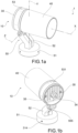
- reference numeral 1 represents a lighting apparatus provided with a light source 20.
- the light source 20 emits a focused (directed), in other words not scattered, light beam, which is therefore provided with a preferential axis and/or plane. In other words, by directing the light source 20, it is possible to direct the light beam.
- the light source 20 comprises a diffuser globe 21 that extends along one plane; in this example, the diffuser globe 21 is semicircular or semi-discoidal. Therefore, the light beam emitted by the light source 20 has a preferential plane that corresponds to the plane of the diffuser globe 21. In this embodiment, the light source 20 emits a light blade beam.
- the light source 20 is provided with a plurality of diffuser globes and therefore emits a light beam that is not scattered, in other words that is provided with a preferential axis and/or plane.
- the light source 20 is an LED.
- the lighting apparatus 1 is an LED spotlight, for example.
- the lighting apparatus 1 comprises a lamp body 10 that is supported by a support 50.
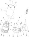
- the lamp body 10 comprises a main body 30, which houses the light source 20 and is covered by an outer body 40, at least in part.
- the main body 30 extends along a longitudinal axis X.
- the main body 30 comprises a front portion 31 in which the light source 20 is fixed, and a rear portion 32 from which a power supply cable (not shown) leaves.
- the main body 30 also houses the printed circuit board 22 for the light source 20.
- a cable grommet 34 for the power supply cable is arranged in the rear portion 32, preferably in the back wall 33.
- the outer body 40 is a casing intended to cover the main body 30, at least in part, in particular in order to conceal the light source 20 from the user's view, while letting out the light beam.
- the outer body 40 also extends along a longitudinal axis X.
- the outer body 40 defines a compartment 43 on the inside, into which at least part of the main body 30 is inserted.
- the outer body 40 is provided with a front opening 41 and with a rear opening 42; the front 41 and rear 42 openings allow access to the compartment 43.
- the outer body 40 and the main body 30 are integrally joined for conjoint rotation by coupling means 44, 35.
- the outer body 40 acts as a handle for the user intending to direct the light beam emitted by the light source 20 of the lighting apparatus 1.
- the user therefore grasps the outer body 40 and rotating it about the longitudinal axis X: due to the coupling means, the rotational movement of the outer body 40 is transmitted to the main body 30 that houses the light source 20. Therefore, the lamp body 10 can rotate about the longitudinal axis X.
- the coupling means are at least one tab 44, which protrudes into the compartment 43 and can engage in a suitable groove 35 (or in a compartment or a depression or a channel) arranged in the main body 30.
- the coupling means 44, 35 preferably also extend along a longitudinal axis X.
- the main body 30 is inserted into the outer body 40 along the longitudinal axis X such that the tab 44 is inserted and slides in the groove 35.
- the coupling means preferably comprise a pair of tabs 44 and a relative pair of grooves 35.
- the tabs 44 are preferably arranged symmetrically on the main body 30.
- the outer body 40 and the main body 30 are preferably fixed to one another by locking means 36.
- the locking means advantageously prevent the main body 30 from leaving the outer body 40, via the front opening 41, by sliding along the longitudinal axis X.
- the locking means comprise a screw 36 that is associated with the main body 30 and can be screwed into a suitable abutment arranged on the outer body 40.
- the screw 36 is preferably inserted from the back wall 33 of the rear portion 32, through the main body 30, and exits in the front portion 31.
- Two locking screws 36 are preferably provided.
- the lighting apparatus 1 also comprises a support 50.
- the support 50 comprises a bearing base 51 from which a stem 52 extends that bears a bracket 53 that can support the lamp body 10.
- the bearing base 51 comprises a stand 511 on which an outer body 512 is arranged such that it can rotate about a vertical axis Y.
- the bracket 53 By fixing the bracket 53 to the outer body 512, the lamp body 10 can also rotate about the vertical axis Y.
- the bearing base 51 preferably comprises anti-rotation means 514, for example screws or grub screws, which lock the outer body 512 with respect to the stand 511 in order to prevent any unwanted rotational movements about the vertical axis Y.
- anti-rotation means 514 for example screws or grub screws, which lock the outer body 512 with respect to the stand 511 in order to prevent any unwanted rotational movements about the vertical axis Y.
- the bracket 53 is fixed to the stem 52 by means of a hinge 54 that allows said bracket to rotate about a transverse axis Z. Therefore, the lamp body 10 can rotate about the vertical axis Y.
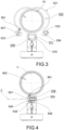
- the bracket 53 comprises an annular body 531, which defines a support compartment 532 into which the lamp body 10 can be inserted.
- the body 531 is preferably obtained from a strip of flexible material folded back on itself to form a ring.
- the body 531 preferably comprises two ends 533 that are joined to one another to form the annular body 531 by means of a bushing-screw system, which is preferably formed by a screw 556 inserted into a bushing 557.
- a bushing-screw system which is preferably formed by a screw 556 inserted into a bushing 557.
- Each end 533 comprises a hole into which the screw 556 or the bushing 533 is inserted.
- the two ends 533 are preferably externally folded with respect to the circumference of the ring to form a socket portion 538.
- the socket portion 538 of the bracket 53 is held in a particular seat 539 arranged in the stem 52.
- the seat 539 is defined between two facing walls 570, each of which is provided with a through-hole 571.
- the socket portion 538 of the bracket 53 is fixed inside the seat 539 arranged in the stem 52 by means of a pin 555.
- the pin 555 is preferably formed by the screw 556 and by the bushing 557 as per the bushing-screw system that closes the annular body 531 of the bracket 53.
- the screw 566 is inserted into the hole 571 in the first facing wall 570 of the stem 52, passes through a first end 533 of the bracket 53 and meets, inside the seat 539, the bushing 557 that has, in turn, firstly been inserted into the hole 571 in the second facing wall 570 of the stem 52 and then passes through a second end 533 of the bracket 53.
- the socket portion 538 of the bracket 53, the seat 539 of the stem 52 and the pin 555 form the hinge 54 that allows said bracket to rotate about the transverse axis Z.
- the seat 539 of the leg 52 represents the female component of the hinge that receives the male component represented by the socket portion 538 of the bracket 53, which are fixed for conjoint rotation by the pin 555 that defines the transverse axis of rotation Z.
- the seat 539 of the stem 52 is preferably dimensioned such that it comfortably receives the socket portion 538 of the bracket 53; that is to say that the seat 539 has a greater width than the width of the socket portion 538 (when this is completely closed by the bushing-screw system).
- the seat 539 is provided with a space 549 that can also accommodate the socket portion 538 when the bushing-screw system is released and the two ends 533 of the annular body 531 move away from one another.
- the lamp body 10, in particular the main body 30, is provided with a support seat 39 defined between a front abutment 391 and a rear abutment 392, into which the bracket 53 of the support 50 is inserted.
- the support seat 39 is preferably an annular groove arranged in the rear portion 32 of the main body 30.
- the annular body 531 of the bracket 53 is widened, separating the two ends 533 such that the lamp body 10 can be inserted into the particular support compartment 532, as shown in Fig. 3 .
- the annular body 531 of the bracket 53 is then closed, coupling the two ends 533 to one another, and inserted into the support seat 39 of the lamp body 10 positioned between the front abutment 391 and the rear abutment 392 of the main body 30.
- the socket portion 538 of the bracket 53 is then inserted into the particular seat 539 arranged in the stem 52.
- the screw 566 and the bushing 557 are therefore inserted into the particular hole 571 in the stem 52, and then cross the particular end 533 of the bracket 53.
- the bushing-screw system is therefore operated by screwing the screw 566 into the bushing in order to completely close the annular body 531 of the bracket 53 around the lamp body 10 by fixing it in position with respect to the support 50 such that it does not rotate about the longitudinal axis X.
- the lamp body 10 is advantageously fixed to the support 50 by means of a releasable tensioning system (bushing-screw system), which is operable between a locked configuration in which the lamp body 10 cannot rotate with respect to the longitudinal axis X, and a released configuration, in which the lamp body 10 can rotate with respect to the longitudinal axis X.
- a releasable tensioning system (bushing-screw system)
- the rotation of the lamp body 10 inside the bracket 53 of the support 50 is preferably circumferentially limited by abutment means.
- the abutment means advantageously limit the rotational movement by slightly less than 360° (for example approximately 358°) such that the electric cables inside the lamp body 10 do not get tangled up.
- the abutment means comprise an abutment 562, which projects from the main body 30 of the lamp body 10 and can abut a particular stop 561 that projects from the annular body 531 of the bracket 53.
- the abutment 562 protrudes externally from inside the support seat 39 of the main body 30 of the lamp body 10; the stop 561 protrudes into the support compartment 532 of the annular body 531 of the bracket 53.
- a lighting apparatus according to the present invention can advantageously be directed in a particularly simple manner.
- the releasable tensioning system advantageously also constitutes the hinge 54 that allows the lamp body 10 to rotate with respect to the support 50.
Landscapes
- Engineering & Computer Science (AREA)
- General Engineering & Computer Science (AREA)
- Fastening Of Light Sources Or Lamp Holders (AREA)
- Lighting Device Outwards From Vehicle And Optical Signal (AREA)
- Non-Portable Lighting Devices Or Systems Thereof (AREA)
Claims (7)
- Beleuchtungsvorrichtung (1), die mit einer Lichtquelle (20) mit einem gerichtetem Lichtstrahl ausgestattet ist, umfassend einen Lampenkörper (10), der sich entlang einer Längsachse (X) erstreckt, und wobei die Lichtquelle (20) aufgenommen ist, gestützt bzw. getragen durch eine Stütze bzw. einen Träger (50), und wobei der Lampenkörper (10) mittels eines lösbaren Spannsystems an dem Träger (50) fixiert bzw. befestigt ist, und zwar operabel zwischen einer verriegelten Konfiguration, in der die Drehung des Lampenkörpers (10) relativ zu der Längsachse (X) verhindert wird, und einer gelösten Konfiguration, in der die Drehung des Lampenkörpers (10) relativ zu der Längsachse (X) erlaubt ist, dadurch gekennzeichnet, dass der Träger (50) eine Lagerbasis (51) und einen Schaft (52) umfasst, der sich von der Basis (51) erstreckt, wobei der Schaft (52) eine Halterung (53) lagert; wobei die Halterung (53) einen ringförmigen Körper (531) umfasst, der ein Stütz- bzw. Trägerfach (532) definiert, in das der Lampenkörper (10) eingesetzt ist, wobei der Körper (531) mit zwei Teilen (533) ausgestattet ist, die durch das lösbare Spannsystem miteinander verbunden sind; wobei die beiden Teile (533) einen Buchsenabschnitt (538) bilden, der in einem Sitz (539) gehalten ist, der in dem Schaft (52) angeordnet ist; wobei das lösbare Spannsystem ein Buchse-Schraube-System ist, das aus einem Stift (555) besteht, der durch eine Schraube (556) gebildet ist, die in eine Buchse (557) eingesetzt ist; wobei der Buchsenabschnitt (538), der Sitz (539) und der Stift (555) ein Scharnier (54) bilden, das die Drehung des Lampenkörpers (10) um eine Querachse (Z) erlaubt.
- Beleuchtungsvorrichtung (1) nach Anspruch 1, wobei der Sitz (539) dahingehend bemessen ist, dass er den Buchsenabschnitt (538) der Halterung (53) leicht aufzunehmen.
- Beleuchtungsvorrichtung (1) nach Anspruch 2, wobei der Sitz (539) breiter ist als die Breite des Buchsenabschnitts (538), wenn sich das lösbare Spannsystem in der verriegelten Konfiguration befindet.
- Beleuchtungsvorrichtung (1) nach einem der vorhergehenden Ansprüche, wobei, wenn sich das lösbare Spannsystem in einer gelösten Konfiguration befindet, die Drehung des Lampenkörpers (10) relativ zu der Längsachse (X) durch Anschlagsmittel in Form von zumindest einem Anschlag (562) begrenzt ist, der so angeordnet ist, dass er von dem Lampenkörper (10) vorsteht, und geeignet ist, gegen zumindest einen jeweiligen Stopp (561) anzuliegen, der so angeordnet ist, dass er von dem Träger (50) vorsteht.
- Beleuchtungsvorrichtung (1) nach einem der vorhergehenden Ansprüche, wobei die Lichtquelle (20) eine LED mit Diffusorkugel (21) ist, die sich entlang einer Ebene parallel zu der Längsachse (X) erstreckt.
- Beleuchtungsvorrichtung (1) nach einem der vorhergehenden Ansprüche, wobei der Lampenkörper (10) einen Hauptkörper (30) umfasst, der die Lichtquelle (20) aufnimmt, eingesetzt zumindest teilweise in das durch einen Außenkörper (40) definierte Fach (43), und wobei der Außenkörper (40) und der Hauptkörper (30) durch Kopplungsmittel drehbar miteinander verbunden sind, die zumindest eine Lasche bzw. einen Fortsatz (44) umfassen, die bzw. der in das Fach (43) hineinragt, eingesetzt in eine an dem Hauptkörper (30) bereitgestellte Nut (45).
- Beleuchtungsvorrichtung (1) nach Anspruch 6, wobei der Außenkörper (40) und der Hauptkörper (30) durch Verriegelungsmittel (36) in Form von zumindest einer Schraube (36) aneinander fixiert bzw. befestigt sind, verbunden mit dem Hauptkörper (30), die in einen speziellen Anschlag geschraubt werden kann, der in dem Außenkörper (40) angeordnet ist.
Applications Claiming Priority (1)
| Application Number | Priority Date | Filing Date | Title |
|---|---|---|---|
| IT102019000005360A IT201900005360A1 (it) | 2019-04-08 | 2019-04-08 | Apparecchio di illuminazione con fascio luminoso direzionato |
Publications (3)
| Publication Number | Publication Date |
|---|---|
| EP3722658A1 EP3722658A1 (de) | 2020-10-14 |
| EP3722658B1 true EP3722658B1 (de) | 2024-09-11 |
| EP3722658C0 EP3722658C0 (de) | 2024-09-11 |
Family
ID=67262865
Family Applications (1)
| Application Number | Title | Priority Date | Filing Date |
|---|---|---|---|
| EP20165575.0A Active EP3722658B1 (de) | 2019-04-08 | 2020-03-25 | Beleuchtungsgerät mit einem ausrichtbaren lichtstrahl |
Country Status (2)
| Country | Link |
|---|---|
| EP (1) | EP3722658B1 (de) |
| IT (1) | IT201900005360A1 (de) |
Citations (3)
| Publication number | Priority date | Publication date | Assignee | Title |
|---|---|---|---|---|
| US3069538A (en) * | 1959-07-17 | 1962-12-18 | Harry E Hobson | Headlight |
| US5438494A (en) * | 1993-09-29 | 1995-08-01 | Harlan; Benjamin L. | Light holder for head gear |
| US5601356A (en) * | 1995-06-16 | 1997-02-11 | Mcwilliams; Dean K. | Flashlight stand and wrist mount system |
Family Cites Families (6)
| Publication number | Priority date | Publication date | Assignee | Title |
|---|---|---|---|---|
| NL145940B (nl) * | 1966-07-23 | 1975-05-15 | Philips Nv | Combinatie van een draagarm en een daaraan bevestigd verlichtingsarmatuur. |
| US20070195520A1 (en) * | 2006-02-17 | 2007-08-23 | O'brien Charles D | Flashlight holder |
| CN102022669B (zh) * | 2009-09-16 | 2013-08-07 | 富准精密工业(深圳)有限公司 | 灯具及其固定装置 |
| EP3336422A1 (de) * | 2016-12-16 | 2018-06-20 | General Electric Company | Leuchtenhalterung |
| CN108204574B (zh) * | 2016-12-19 | 2020-06-09 | 光宝电子(广州)有限公司 | 可调式固定结构以及照明装置 |
| TWI625490B (zh) * | 2017-08-04 | 2018-06-01 | 光寶科技股份有限公司 | 用於燈具之燈桿固定結構及應用其之照明裝置 |
-
2019
- 2019-04-08 IT IT102019000005360A patent/IT201900005360A1/it unknown
-
2020
- 2020-03-25 EP EP20165575.0A patent/EP3722658B1/de active Active
Patent Citations (3)
| Publication number | Priority date | Publication date | Assignee | Title |
|---|---|---|---|---|
| US3069538A (en) * | 1959-07-17 | 1962-12-18 | Harry E Hobson | Headlight |
| US5438494A (en) * | 1993-09-29 | 1995-08-01 | Harlan; Benjamin L. | Light holder for head gear |
| US5601356A (en) * | 1995-06-16 | 1997-02-11 | Mcwilliams; Dean K. | Flashlight stand and wrist mount system |
Also Published As
| Publication number | Publication date |
|---|---|
| EP3722658A1 (de) | 2020-10-14 |
| IT201900005360A1 (it) | 2020-10-08 |
| EP3722658C0 (de) | 2024-09-11 |
Similar Documents
| Publication | Publication Date | Title |
|---|---|---|
| US5289358A (en) | Recessed luminaire with a swivel housing | |
| US9523490B2 (en) | Reflectors and reflector orientation feature to prevent non-qualified trim | |
| EP3722658B1 (de) | Beleuchtungsgerät mit einem ausrichtbaren lichtstrahl | |
| JP6601665B2 (ja) | 照明器具 | |
| US6199813B1 (en) | Ceiling fixture decoration assembly | |
| US11028985B1 (en) | Surface mountable spotlight housing | |
| US10591145B2 (en) | Luminaire | |
| US9851081B2 (en) | Wedge shaped heat sink for gimbal mounted solid state recessed lighting | |
| JP5571841B1 (ja) | Led照明器具 | |
| GB2624941A (en) | Improvements to an electrical fitting | |
| JP6591790B2 (ja) | 照明装置 | |
| JP6646252B2 (ja) | 照明器具 | |
| JP2018181753A (ja) | 照明器具 | |
| CA3069448C (en) | Surface mountable spotlight housing | |
| JP2010123535A (ja) | 照明器具 | |
| CN214038092U (zh) | 嵌灯 | |
| CN105539237A (zh) | 组合式拉手和光源总成 | |
| JP2015088458A (ja) | Led照明器具 | |
| JP6275066B2 (ja) | Led照明器具 | |
| US3882307A (en) | Lamp socket mount | |
| JP2015088454A (ja) | Led照明器具 | |
| IT201900001180U1 (it) | Apparecchio di illuminazione con fascio luminoso direzionato | |
| EP3232122B1 (de) | Integrierte kardanische aufhängung für einstellbare leuchte | |
| US1086426A (en) | Lighting-fixture. | |
| JP2016219161A (ja) | 照明装置 |
Legal Events
| Date | Code | Title | Description |
|---|---|---|---|
| PUAI | Public reference made under article 153(3) epc to a published international application that has entered the european phase |
Free format text: ORIGINAL CODE: 0009012 |
|
| STAA | Information on the status of an ep patent application or granted ep patent |
Free format text: STATUS: THE APPLICATION HAS BEEN PUBLISHED |
|
| AK | Designated contracting states |
Kind code of ref document: A1 Designated state(s): AL AT BE BG CH CY CZ DE DK EE ES FI FR GB GR HR HU IE IS IT LI LT LU LV MC MK MT NL NO PL PT RO RS SE SI SK SM TR |
|
| AX | Request for extension of the european patent |
Extension state: BA ME |
|
| STAA | Information on the status of an ep patent application or granted ep patent |
Free format text: STATUS: REQUEST FOR EXAMINATION WAS MADE |
|
| 17P | Request for examination filed |
Effective date: 20210408 |
|
| RBV | Designated contracting states (corrected) |
Designated state(s): AL AT BE BG CH CY CZ DE DK EE ES FI FR GB GR HR HU IE IS IT LI LT LU LV MC MK MT NL NO PL PT RO RS SE SI SK SM TR |
|
| STAA | Information on the status of an ep patent application or granted ep patent |
Free format text: STATUS: EXAMINATION IS IN PROGRESS |
|
| 17Q | First examination report despatched |
Effective date: 20220803 |
|
| GRAP | Despatch of communication of intention to grant a patent |
Free format text: ORIGINAL CODE: EPIDOSNIGR1 |
|
| STAA | Information on the status of an ep patent application or granted ep patent |
Free format text: STATUS: GRANT OF PATENT IS INTENDED |
|
| INTG | Intention to grant announced |
Effective date: 20240529 |
|
| GRAS | Grant fee paid |
Free format text: ORIGINAL CODE: EPIDOSNIGR3 |
|
| GRAA | (expected) grant |
Free format text: ORIGINAL CODE: 0009210 |
|
| STAA | Information on the status of an ep patent application or granted ep patent |
Free format text: STATUS: THE PATENT HAS BEEN GRANTED |
|
| AK | Designated contracting states |
Kind code of ref document: B1 Designated state(s): AL AT BE BG CH CY CZ DE DK EE ES FI FR GB GR HR HU IE IS IT LI LT LU LV MC MK MT NL NO PL PT RO RS SE SI SK SM TR |
|
| REG | Reference to a national code |
Ref country code: GB Ref legal event code: FG4D |
|
| REG | Reference to a national code |
Ref country code: CH Ref legal event code: EP |
|
| REG | Reference to a national code |
Ref country code: DE Ref legal event code: R096 Ref document number: 602020037405 Country of ref document: DE |
|
| REG | Reference to a national code |
Ref country code: IE Ref legal event code: FG4D |
|
| U01 | Request for unitary effect filed |
Effective date: 20241002 |
|
| U07 | Unitary effect registered |
Designated state(s): AT BE BG DE DK EE FI FR IT LT LU LV MT NL PT RO SE SI Effective date: 20241024 |
|
| PG25 | Lapsed in a contracting state [announced via postgrant information from national office to epo] |
Ref country code: NO Free format text: LAPSE BECAUSE OF FAILURE TO SUBMIT A TRANSLATION OF THE DESCRIPTION OR TO PAY THE FEE WITHIN THE PRESCRIBED TIME-LIMIT Effective date: 20241211 |
|
| PG25 | Lapsed in a contracting state [announced via postgrant information from national office to epo] |
Ref country code: GR Free format text: LAPSE BECAUSE OF FAILURE TO SUBMIT A TRANSLATION OF THE DESCRIPTION OR TO PAY THE FEE WITHIN THE PRESCRIBED TIME-LIMIT Effective date: 20241212 |
|
| PG25 | Lapsed in a contracting state [announced via postgrant information from national office to epo] |
Ref country code: HR Free format text: LAPSE BECAUSE OF FAILURE TO SUBMIT A TRANSLATION OF THE DESCRIPTION OR TO PAY THE FEE WITHIN THE PRESCRIBED TIME-LIMIT Effective date: 20240911 |
|
| PG25 | Lapsed in a contracting state [announced via postgrant information from national office to epo] |
Ref country code: ES Free format text: LAPSE BECAUSE OF FAILURE TO SUBMIT A TRANSLATION OF THE DESCRIPTION OR TO PAY THE FEE WITHIN THE PRESCRIBED TIME-LIMIT Effective date: 20240911 Ref country code: RS Free format text: LAPSE BECAUSE OF FAILURE TO SUBMIT A TRANSLATION OF THE DESCRIPTION OR TO PAY THE FEE WITHIN THE PRESCRIBED TIME-LIMIT Effective date: 20241211 |
|
| PG25 | Lapsed in a contracting state [announced via postgrant information from national office to epo] |
Ref country code: RS Free format text: LAPSE BECAUSE OF FAILURE TO SUBMIT A TRANSLATION OF THE DESCRIPTION OR TO PAY THE FEE WITHIN THE PRESCRIBED TIME-LIMIT Effective date: 20241211 Ref country code: NO Free format text: LAPSE BECAUSE OF FAILURE TO SUBMIT A TRANSLATION OF THE DESCRIPTION OR TO PAY THE FEE WITHIN THE PRESCRIBED TIME-LIMIT Effective date: 20241211 Ref country code: HR Free format text: LAPSE BECAUSE OF FAILURE TO SUBMIT A TRANSLATION OF THE DESCRIPTION OR TO PAY THE FEE WITHIN THE PRESCRIBED TIME-LIMIT Effective date: 20240911 Ref country code: GR Free format text: LAPSE BECAUSE OF FAILURE TO SUBMIT A TRANSLATION OF THE DESCRIPTION OR TO PAY THE FEE WITHIN THE PRESCRIBED TIME-LIMIT Effective date: 20241212 Ref country code: ES Free format text: LAPSE BECAUSE OF FAILURE TO SUBMIT A TRANSLATION OF THE DESCRIPTION OR TO PAY THE FEE WITHIN THE PRESCRIBED TIME-LIMIT Effective date: 20240911 |
|
| U20 | Renewal fee for the european patent with unitary effect paid |
Year of fee payment: 6 Effective date: 20250122 |
|
| PG25 | Lapsed in a contracting state [announced via postgrant information from national office to epo] |
Ref country code: IS Free format text: LAPSE BECAUSE OF FAILURE TO SUBMIT A TRANSLATION OF THE DESCRIPTION OR TO PAY THE FEE WITHIN THE PRESCRIBED TIME-LIMIT Effective date: 20250111 |
|
| PG25 | Lapsed in a contracting state [announced via postgrant information from national office to epo] |
Ref country code: SM Free format text: LAPSE BECAUSE OF FAILURE TO SUBMIT A TRANSLATION OF THE DESCRIPTION OR TO PAY THE FEE WITHIN THE PRESCRIBED TIME-LIMIT Effective date: 20240911 |
|
| PG25 | Lapsed in a contracting state [announced via postgrant information from national office to epo] |
Ref country code: CZ Free format text: LAPSE BECAUSE OF FAILURE TO SUBMIT A TRANSLATION OF THE DESCRIPTION OR TO PAY THE FEE WITHIN THE PRESCRIBED TIME-LIMIT Effective date: 20240911 Ref country code: PL Free format text: LAPSE BECAUSE OF FAILURE TO SUBMIT A TRANSLATION OF THE DESCRIPTION OR TO PAY THE FEE WITHIN THE PRESCRIBED TIME-LIMIT Effective date: 20240911 |
|
| PG25 | Lapsed in a contracting state [announced via postgrant information from national office to epo] |
Ref country code: SK Free format text: LAPSE BECAUSE OF FAILURE TO SUBMIT A TRANSLATION OF THE DESCRIPTION OR TO PAY THE FEE WITHIN THE PRESCRIBED TIME-LIMIT Effective date: 20240911 |
|
| PLBE | No opposition filed within time limit |
Free format text: ORIGINAL CODE: 0009261 |
|
| STAA | Information on the status of an ep patent application or granted ep patent |
Free format text: STATUS: NO OPPOSITION FILED WITHIN TIME LIMIT |
|
| 26N | No opposition filed |
Effective date: 20250612 |
|
| PG25 | Lapsed in a contracting state [announced via postgrant information from national office to epo] |
Ref country code: MC Free format text: LAPSE BECAUSE OF FAILURE TO SUBMIT A TRANSLATION OF THE DESCRIPTION OR TO PAY THE FEE WITHIN THE PRESCRIBED TIME-LIMIT Effective date: 20240911 |
|
| REG | Reference to a national code |
Ref country code: CH Ref legal event code: H13 Free format text: ST27 STATUS EVENT CODE: U-0-0-H10-H13 (AS PROVIDED BY THE NATIONAL OFFICE) Effective date: 20251023 |
|
| GBPC | Gb: european patent ceased through non-payment of renewal fee |
Effective date: 20250325 |