EP3722261B1 - Ein wasserenthärtungsgerät - Google Patents
Ein wasserenthärtungsgerät Download PDFInfo
- Publication number
- EP3722261B1 EP3722261B1 EP20164592.6A EP20164592A EP3722261B1 EP 3722261 B1 EP3722261 B1 EP 3722261B1 EP 20164592 A EP20164592 A EP 20164592A EP 3722261 B1 EP3722261 B1 EP 3722261B1
- Authority
- EP
- European Patent Office
- Prior art keywords
- water
- service
- meter
- regeneration
- disc
- Prior art date
- Legal status (The legal status is an assumption and is not a legal conclusion. Google has not performed a legal analysis and makes no representation as to the accuracy of the status listed.)
- Active
Links
Images




Classifications
-
- B—PERFORMING OPERATIONS; TRANSPORTING
- B01—PHYSICAL OR CHEMICAL PROCESSES OR APPARATUS IN GENERAL
- B01J—CHEMICAL OR PHYSICAL PROCESSES, e.g. CATALYSIS OR COLLOID CHEMISTRY; THEIR RELEVANT APPARATUS
- B01J47/00—Ion-exchange processes in general; Apparatus therefor
- B01J47/02—Column or bed processes
- B01J47/022—Column or bed processes characterised by the construction of the column or container
-
- B—PERFORMING OPERATIONS; TRANSPORTING
- B01—PHYSICAL OR CHEMICAL PROCESSES OR APPARATUS IN GENERAL
- B01J—CHEMICAL OR PHYSICAL PROCESSES, e.g. CATALYSIS OR COLLOID CHEMISTRY; THEIR RELEVANT APPARATUS
- B01J49/00—Regeneration or reactivation of ion-exchangers; Apparatus therefor
- B01J49/75—Regeneration or reactivation of ion-exchangers; Apparatus therefor of water softeners
-
- B—PERFORMING OPERATIONS; TRANSPORTING
- B01—PHYSICAL OR CHEMICAL PROCESSES OR APPARATUS IN GENERAL
- B01J—CHEMICAL OR PHYSICAL PROCESSES, e.g. CATALYSIS OR COLLOID CHEMISTRY; THEIR RELEVANT APPARATUS
- B01J49/00—Regeneration or reactivation of ion-exchangers; Apparatus therefor
- B01J49/80—Automatic regeneration
-
- B—PERFORMING OPERATIONS; TRANSPORTING
- B01—PHYSICAL OR CHEMICAL PROCESSES OR APPARATUS IN GENERAL
- B01J—CHEMICAL OR PHYSICAL PROCESSES, e.g. CATALYSIS OR COLLOID CHEMISTRY; THEIR RELEVANT APPARATUS
- B01J49/00—Regeneration or reactivation of ion-exchangers; Apparatus therefor
- B01J49/80—Automatic regeneration
- B01J49/85—Controlling or regulating devices therefor
-
- C—CHEMISTRY; METALLURGY
- C02—TREATMENT OF WATER, WASTE WATER, SEWAGE, OR SLUDGE
- C02F—TREATMENT OF WATER, WASTE WATER, SEWAGE, OR SLUDGE
- C02F1/00—Treatment of water, waste water, or sewage
- C02F1/42—Treatment of water, waste water, or sewage by ion-exchange
-
- C—CHEMISTRY; METALLURGY
- C02—TREATMENT OF WATER, WASTE WATER, SEWAGE, OR SLUDGE
- C02F—TREATMENT OF WATER, WASTE WATER, SEWAGE, OR SLUDGE
- C02F1/00—Treatment of water, waste water, or sewage
- C02F1/42—Treatment of water, waste water, or sewage by ion-exchange
- C02F2001/425—Treatment of water, waste water, or sewage by ion-exchange using cation exchangers
-
- C—CHEMISTRY; METALLURGY
- C02—TREATMENT OF WATER, WASTE WATER, SEWAGE, OR SLUDGE
- C02F—TREATMENT OF WATER, WASTE WATER, SEWAGE, OR SLUDGE
- C02F2201/00—Apparatus for treatment of water, waste water or sewage
- C02F2201/002—Construction details of the apparatus
- C02F2201/005—Valves
-
- C—CHEMISTRY; METALLURGY
- C02—TREATMENT OF WATER, WASTE WATER, SEWAGE, OR SLUDGE
- C02F—TREATMENT OF WATER, WASTE WATER, SEWAGE, OR SLUDGE
- C02F2209/00—Controlling or monitoring parameters in water treatment
- C02F2209/40—Liquid flow rate
-
- C—CHEMISTRY; METALLURGY
- C02—TREATMENT OF WATER, WASTE WATER, SEWAGE, OR SLUDGE
- C02F—TREATMENT OF WATER, WASTE WATER, SEWAGE, OR SLUDGE
- C02F2303/00—Specific treatment goals
- C02F2303/16—Regeneration of sorbents, filters
Definitions
- a water softener apparatus generally comprises an active resin water softening component that has to be regenerated occasionally by-passing brine through it. Whilst the component is being regenerated it is inoperable to supply softened water. In known domestic water softeners, this problem is ameliorated by arranging for regeneration to take place at a time of likely low demand, for example during the very early morning. Also known are water softeners comprising two softening components which are regenerated during respective different time intervals so that at least one of them is operable all the time, for example as disclosed in US Patent No. 5,273, 070 .
- the apparatus according to this patent comprises an electrically motorized valve arrangement controlled by a microprocessor which is programmed to sequence the operations of the valve arrangement.
- this requires an electrical supply to the water softener which, in some cases, may be inconvenient and/or which may add to the cost of installation of the softener.
- US4539106 uses pegs radially distributed around a meter wheel to enable adjustment of an amount of water necessary to be measured to initiate regeneration of a water softener tank.
- US2013/248457 discloses a means of incrementally adjusting the amount of water to be measured to initiate regeneration of a water softener tank by relative rotation between first and second meter discs which is resisted by an anti-rotation pawl that engages at least one of the meter discs.
- At least one of the meter discs includes a disc structure engageable by an external adjustment member which can be manipulated to overcome the force applied by the anti-rotation pawl in order to rotate one meter disc relative to the other meter disc.
- WO2009/133251 discloses a regulator operable from the outside of the water softener with which the start of a regeneration cycle can be regulated according to the quantity of water to be treated.
- the system for regulating systems comprises a rotary geared element which is engaged by a pinion which is externally accessible for adjusting the rotated position of the rotary element.
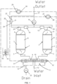
- the ports 6 at the upper ends 4 of the tanks 1 and 2 are connected via respective check valves 14 and 15 to a common input of the service meter 16.
- An output of this meter leads via pipe 17 to the softened water outlet of the softener apparatus.
- This pipe will be connected in use via a union (not shown) to the user's domestic stored water system (not shown).
- the softener also comprises a brine tank 18 and brine valve 19 connected to an injection input 20 of an injector 21 which also has an input port 22 connected to the softened water outlet pipe 17.
- An outlet port 24 of the injector 21 leads via respective further check valves 25 and 26 to the ports 6 at the upper ends of the tanks 1 and 2, i.e. so that the port 6 at the top of tank 1 is connected to both check valves 14 and 25 while port 6 at the top of tank 2 is connected to check valves 15 and 26.
- the injector 21 comprises a duct between the input and output ports 22 and 24 which duct is shaped to provide a restriction and hence a pressure drop when water is flowing through it from pipe 17. This causes brine from the tank 20 to be sucked into the injector 21 and mixed with the softened water flowing from the outlet port 24.
- the service meter 16 measures the flow of softened water supplied by the water softener.
- the meter operates the service valves 27 and 28 so that each time a predetermined quantity of softened water has been supplied, regeneration of one of the tanks is started.
- the regeneration meter 23 operates via regeneration valves 29 and 30 to set a predetermined quantity of water to pass through the tank being regenerated.
- brine from tank 18 is mixed with this water for a time (controlled by the brine valve 19).
- the position of the regeneration meter 23 is important. Previously, it has been known to position the regeneration meter in the pipe leading from the water outlet pipe 17 to the input port 22 of the injector.
- the regeneration meter 23 is measuring only softened water being fed to the injector port 22 rather than the amount of softened water with injected brine required to flow through the tank 1, 2 being regenerated.
- the water regeneration meter is preferably positioned in the apparatus at a point downstream of where brine for regeneration of the two water softener components is received into the apparatus, i.e. downstream of the injector 21, such that the regeneration meter 23 measures the volume of softened water and brine being used to regenerate one of the tanks 1, 2. This provides a more accurate operation of the regeneration meter in terminating alternate regeneration of the tanks 1, 2.
- softened water from both tanks 1 or 2 enters the meter 16 and passes through the metering chamber 40.
- This metering chamber contains a piston type water meter which measures accurately the volume of water passing through to the outlet pipe 17.
- the meter chamber drives the service meter cam 41 via a series of gears 42.
- One rotation of the service meter cam is equivalent to the pre-set volume of water that may be softened by both resin tanks.
- the blade 24 wipes past the lever blade 43 and closes the service meter valve 'locking in' the water pressure to the shuttle valve port 31.
- the volume of water required to wipe the blades past each other is less than the pre-set volume of water required to regenerate a resin tank.
- Service lever 45 operates service valve 27 and starts the regeneration of resin tank 1.
- service lever 50 with blade 51 operates service valve 28 and applies a pressure signal to shuttle valve port 32 to start the regeneration of resin tank 2.
- the lever blades 44 and 45 are positioned at 180 degrees to each other, therefore, the regeneration of either tank is 50% of the pre-set volume of one rotation of the service meter cam.
- the pre-set volume may be altered by changing the ratio of the gear chain between the meter chamber and the service cam.
- softened water enters the metering chamber 61 of the regeneration meter 23 and flows through the metering chamber 61.
- This chamber again contains a piston type water meter which accurately measures the volume of water passing through the meter chamber.
- the meter chamber drives the regeneration cam 62 via a series of gears 63.
- Half a rotation of the regeneration meter cam is equivalent to the pre-set volume of water with entrained brine necessary to regenerate one resin tank.
- the regeneration meter cam 62 is positioned so that regeneration lever 64 is 'free' and therefore regeneration valve 29 is closed. This 'locks in' the pressure signal from the service valve 27 which opens drain shuttle valve port 31.
- the regeneration meter cam has pushed open the regeneration valve 30 via lever 65, this prevents resin tank 2 from regenerating at the same time as resin tank 1 by venting any pressure signal to drain shuttle valve port 32.
- the regeneration of resin tank 1 is started by a water pressure signal from the service valve 27 which opens drain shuttle 70.
- the path of water to flow to drain is now open, the flow of water to drain now pushing across piston 75 and closing the valve seal on its seat. Hard water can only now flow to resin tank 1 for softening.
- the regeneration water now flows from resin tank 1 past piston 75 through the open drain shuttle and then to drain.
- softened water fills the brine tank 18 via the brine valve 19 until shut off by the brine valve float 80 to a level above the platform 81.
- the salt 82 is gradually dissolved in the water producing brine.
- Brine continues to be sucked from the brine tank until the brine level stops filling when it reaches the height of the walls of a cup-shaped weir 85.
- the level continues to fall in the weir chamber 84 until it reaches a point which enables the upper seal 85 to check shut and no more brine is sucked from the brine tank.
- Water continues to flow through the injector to flush any brine to drain from the resin tank.
- the amount of brine being capable of being sucked from the brine tank may be adjusted by raising or lowering the brine valve relative to the weir. This raises or lowers the shut off point of the water refilling the brine tank, thus adjusting the volume of brine.
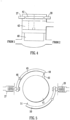
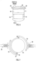
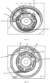
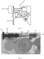
- FIG. 10 shown is an embodiment of a displacement meter 100 according to the present invention.
- the circled portion of the displacement meter 100 in Fig. 10 is more clearly seen in enlarged form in Figs. 12 and 13 .
- the displacement meter 100 embodies at least the service meter 16 and regeneration meter 23 of Figs. 1 to 9 .
- the centre drive dog 118 causes rotation of the spur gear train 120 positioned just above the chamber 110.
- the spur gear train 120 has a fixed gear ratio.
- the spur gear train 120 causes rotation of a worm gear 136 which rotates a slideable spur gear 138 causing rotation of the snail cam 134.
- the slideable spur gear 138 is mounted on the snail cam 134.
- Rotation of the snail cam 134 in turn causes the cam 126 of the service follower disc to move along the surface of the snail tooth 132 of the snail cam 134 thus rotating the service follower disc 128 in what can be considered a forward direction of rotation.
- tension is built up in a biasing means such as a tension spring 140.
- the service drive disc 144 rotates, it moves along a second ratchet and pal system 146 with a gearbox lid 148. It also engages a contact key feature of a control disc 150 thus rotating the control disc 150 around a centre pin 152.
- the service drive disc 144 directly drives the control disc 150 and a ceramic disc 154 and together these can be considered as comprising the second mechanism 130.
- As the control disc 150 rotates pressure from a pressure feed hole and drain pressure from a drain pressure feed hole are distributed to relevant valves in the water softener apparatus.
- the control disc 150 and the ceramic disc 154 are arranged such that, for a set amount of forward rotation, they trigger one or more events such as regeneration events.
- the triggering of events is directly related to the number of strokes needed to be made by the cam 126 of the service follower disc 128 to cause, via the service drive disc 144, a set amount of rotation of the control drive disc 150 and the ceramic disc 154 to trigger events.
- the adjustable number of the finite volumes of water flow needed to complete one stroke of the cam 126 of the service follower disc 128 to the triggering of a regeneration or like event i.e.
- the adjuster knob 124 is accessible at an exterior of the water softener apparatus and, when the knob 124 is rotated, this causes backward or forward movement of the snail cam 134 relative to the service follower disc 128 (leftwards and rightwards movement when viewed in Fig. 13 ).
- An adjusted position of the snail cam 134 relative to the service follower disc 128 results in a different stroke starting position for the service follower disc cam 126 on the surface of the snail cam 134 which therefore requires more or less pushes to the control disc 150 and the ceramic disc 154 to trigger a regeneration event dependent on the degree of adjustment of the adjustment mechanism 122.
Landscapes
- Chemical & Material Sciences (AREA)
- Organic Chemistry (AREA)
- Chemical Kinetics & Catalysis (AREA)
- Life Sciences & Earth Sciences (AREA)
- Hydrology & Water Resources (AREA)
- Engineering & Computer Science (AREA)
- Environmental & Geological Engineering (AREA)
- Water Supply & Treatment (AREA)
- Treatment Of Water By Ion Exchange (AREA)
Claims (2)
- Wasserenthärtungsanlage, die Folgendes umfasst:zwei harzhaltige Wasserenthärtungstanks (1, 2), die jeweils eine obere Öffnung (6) und eine untere Öffnung (6) aufweisen, wobei die unteren Öffnungen (6) der beiden Wasserenthärtungstanks (1, 2) über jeweilige Kammern (9, 10) eines Wechselventils (11) mit einem Wassereinlass (12) verbunden sind, der eine Versorgung mit zu enthärtendem Wasser bereitstellt, wobei die unteren Öffnungen (6) auch über einen Anschluss (13) des Wechselventils (11) mit einem Abfluss über einen Aufbereitungsmesser (23) verbunden sind, der einen Teil eines Aufbereitungssystems zum abwechselnden Aufbereiten der beiden Wasserenthärtungstanks (1, 2) bildet, wobei die oberen Öffnungen (6) der beiden Wasserenthärtungstanks (1, 2) über jeweilige Rückschlagventile (14, 15) mit einem gemeinsamen Eingang eines wasserbetriebenen Durchflussmessers (16) verbunden sind, wobei ein Ausgang des wasserbetriebenen Durchflussmessers (16) über eine Auslassleitung (17) für enthärtetes Wasser zu einem Auslass für enthärtetes Wasser der Wasserenthärtungsanlage führt;einen Soletank (18) und ein Soleventil (19), das mit einem Einspritzeingang (20) eines Injektors (21) verbunden ist, der eine mit der Auslassleitung (17) für enthärtetes Wasser verbundene Eingangsöffnung (22) und eine Auslassöffnung (24) aufweist, die über weitere jeweilige Rückschlagventile (25, 26) zu den oberen Öffnungen (6) der beiden Wasserenthärtungstanks (1, 2) führt, wobei der Injektor (21) eine Rohrleitung zwischen der Einlassöffnung (22) und der Auslassöffnung (24) umfasst, die so geformt ist, dass sie eine Verengung bildet, die bewirkt, dass Sole aus dem Soletank (18) in den Injektor (21) gesaugt und mit dem aus der Auslassöffnung (24) fließenden enthärteten Wasser gemischt wird, wobei das enthärtete Wasser an der Einlassöffnung (22) des Injektors (21) von der Auslassleitung (17) für enthärtetes Wasser empfangen wird;wobei der wasserbetriebene Durchflussmesser (16) so konfiguriert ist, dass er zwei Betriebsventile (27, 28) steuert, um zu bewirken, dass die beiden Wasserenthärtungstanks (1, 2) außer Betrieb gesetzt werden, um Wasser in jeweils unterschiedlichen Intervallen zu enthärten, so dass mindestens ein Wasserenthärtungstank (1, 2) die ganze Zeit über betriebsbereit ist, wobei die beiden Betriebsventile (27, 28) betätigbar sind, um das Wechselventil (11) über jeweilige Steueranschlüsse (31, 32) des Wechselventils (11) zu steuern, wobei der wasserbetriebene Durchflussmesser (16) so konfiguriert ist, dass er einen Wasserfluss misst, so dass jedes Mal, wenn eine vorbestimmte Wassermenge gemessen wurde, die Aufbereitung eines der Tanks eingeleitet wird;wobei der wasserbetriebene Durchflussmesser (16) in einem Wasserverdrängungsmesser (100) enthalten ist, der auch den Aufbereitungsmesser (23) verkörpert und einen Einstellmechanismus (122) zum Einstellen der Menge der vorbestimmten Wassermenge enthält, die gemessen werden muss, um die Aufbereitung eines der Wasserenthärtungstanks (1, 2) einzuleiten, wobei der Wasserverdrängungsmesser (100) eine Kammer (110) zur Aufnahme eines Wasserstroms umschließt, wobei die Kammer (110) einen Einlass (112) und einen Auslass (114) aufweist, wobei die Kammer (110) einen ersten Mechanismus (116) aufweist, der einen Teil des wasserbetriebenen Durchflussmessers (16) bildet, der durch Wasser angetrieben wird, das durch den Einlass (112) in Richtung des Auslasses (114) fließt, wodurch ein vorbestimmtes endliches Volumen an Wasser, das durch den Einlass (112) in Richtung des Auslasses (114) fließt, bewirkt, dass der erste Mechanismus (116) eine Umdrehung um die Kammer (110) herum vollendet, um dadurch eine Menge an Fluid zu messen, die über die Zeit durch die Kammer (110) fließt, wobei eine Anzahl der endlichen Wasservolumina, die gemessen werden, mit einer Hublänge eines Führungselements (126) einer Betriebsmitnehmerscheibe (128) in Beziehung steht, wobei die Betriebsmitnehmerscheibe (128) in einem zweiten Mechanismus (130) des Wasserverdrängungsmessers (100) enthalten ist, um die Aufbereitung eines der beiden Wasserenthärtungstanks (1, 2) durch den Aufbereitungsmesser (23) in Reaktion auf das Messen einer ausgewählten oder berechneten Wassermenge, die durch die Kammer (110) des Verdrängungsmessers (100) fließt, einzuleiten, wobei der Einstellmechanismus (122) einen drehbaren Schneckennocken (134) umfasst, der durch den ersten Mechanismus (116) über einen Getriebemechanismus (118, 120, 136, 138) gedreht wird, der bewirkt, dass sich das Führungselement (126) der Betriebsmitnehmerscheibe (128) entlang einer Oberfläche eines Schneckenzahns (132) des drehbaren Schneckennockens (134) bewegt, um die Betriebsmitnehmerscheibe (128) in einer Vorwärtsrichtung zu drehen, bis das Führungselement (126) von der Oberfläche des Schneckenzahns (132) abfällt, wobei ein Vorspannmittel (14) bewirkt, dass sich die Betriebsmitnehmerscheibe (128) gegenläufig dreht und in eine Ausgangsposition zurückkehrt, in der das Führungselement (126) den Schneckenzahn (132) an oder in der Nähe eines Basispunkts des Schneckenzahns (132) berührt, wobei der zweite Mechanismus (130) einen ersten Sperrklinkenradmechanismus (142) umfasst, der von der Betriebsmitnehmerscheibe (128) angetrieben wird, wobei der Sperrklinkenradmechanismus (142) in eine Betriebsantriebsscheibe (144) eingreift, um sie in der gleichen Vorwärtsrichtung wie die Betriebsmitnehmerscheibe (128) zu drehen, so dass, sobald die Betriebsantriebsscheibe (144) in der Vorwärtsrichtung um eine ausreichenden Betrag gedreht worden ist, sie die Aufbereitung eines der Wasserenthärtungstanks (1, 2) einleitet;wobei die Betriebsantriebsscheibe (144) so konfiguriert ist, dass sie sich entlang eines zweiten Sperrklinkenradsystems (146) mit einem Getriebedeckel (148) bewegt und ihre vorwärts gedrehte Position beibehält, wenn sich die Betriebsmitnehmerscheibe (128) aufgrund des zweiten Sperrklinkenradsystems (146) mit Getriebedeckel (148), das so konfiguriert ist, dass es eine Rückwärtsbewegung der Betriebsantriebsscheibe (144) verhindert, gegenläufig dreht;wobei die Betriebsantriebsscheibe (144) ferner so konfiguriert ist, dass sie eine Steuerscheibe (150) und eine Keramikscheibe (154) des zweiten Mechanismus (130) direkt antreibt, die so angeordnet sind, dass sie bei einem bestimmten Drehbetrag ein Aufbereitungsereignis auslösen;wobei die Menge der vorbestimmten Wassermenge, die gemessen werden muss, um die Aufbereitung eines der Tanks (1, 2) einzuleiten, mit der Hublänge des Führungselements (126) entlang des Schneckenzahns (132) in Beziehung steht;wobei ein Einstellknopf (124) des Einstellmechanismus (122) so konfiguriert ist, dass er sich dreht und eine Rückwärts- oder Vorwärtsbewegung der Schneckennocke (134) relativ zu der Betriebsmitnehmerscheibe (128) bewirkt, um die Position der Schneckennocke (134) relativ zu der Betriebsmitnehmerscheibe (128) einzustellen, was zu einer unterschiedlichen Hubstartposition des Führungselements (126) entlang der Oberfläche des Schneckenzahns (132) führt; undwobei der Einstellmechanismus (122) innerhalb eines vorbestimmten Einstellbereichs stufenlos einstellbar ist.
- Wasserenthärtungsanlage nach Anspruch 1, wobei der Einstellmechanismus (122) von einer Außenseite der Wasserenthärtungsanlage manuell einstellbar ist.
Applications Claiming Priority (1)
| Application Number | Priority Date | Filing Date | Title |
|---|---|---|---|
| GB1903775.3A GB2583448B (en) | 2019-03-20 | 2019-03-20 | A water softener apparatus |
Publications (3)
| Publication Number | Publication Date |
|---|---|
| EP3722261A2 EP3722261A2 (de) | 2020-10-14 |
| EP3722261A3 EP3722261A3 (de) | 2020-12-09 |
| EP3722261B1 true EP3722261B1 (de) | 2024-12-04 |
Family
ID=66381059
Family Applications (1)
| Application Number | Title | Priority Date | Filing Date |
|---|---|---|---|
| EP20164592.6A Active EP3722261B1 (de) | 2019-03-20 | 2020-03-20 | Ein wasserenthärtungsgerät |
Country Status (3)
| Country | Link |
|---|---|
| EP (1) | EP3722261B1 (de) |
| DK (1) | DK3722261T3 (de) |
| GB (1) | GB2583448B (de) |
Citations (1)
| Publication number | Priority date | Publication date | Assignee | Title |
|---|---|---|---|---|
| GB2362114A (en) * | 2000-05-09 | 2001-11-14 | Kinetico Ltd | Flow controlled regeneration of water treatment apparatus |
Family Cites Families (13)
| Publication number | Priority date | Publication date | Assignee | Title |
|---|---|---|---|---|
| DE2300606C3 (de) * | 1973-01-08 | 1980-06-19 | Gebrueder Heyl Kg Gesellschaft Fuer Analysentechnik, 3200 Hildesheim | Schalteinrichtung zur Auslosung des Regenerationsbetriebes einer Wasserenthärtungsanlage |
| DE2807635A1 (de) * | 1978-02-22 | 1979-08-30 | Judo Wasseraufbereitung | Steuerung fuer haushalts-wasseraufbereitungsanlagen |
| US4313825A (en) * | 1981-02-23 | 1982-02-02 | L. W. Fleckenstein, Inc. | Control system for meter actuated regeneration in a water treatment system |
| US4539106A (en) * | 1983-12-02 | 1985-09-03 | Charles E. Cates | System and apparatus for water conditioning |
| US5273070A (en) | 1989-10-05 | 1993-12-28 | Culligan International Company | Water treatment apparatus |
| DE4300585C2 (de) | 1993-01-13 | 1994-12-15 | Rudolf Schenk | Flüssigkeitsaufbereitungsanlage |
| JPH08117745A (ja) * | 1994-10-24 | 1996-05-14 | Matsushita Electric Ind Co Ltd | 蒸気発生装置用の軟水器 |
| BE1010440A3 (nl) * | 1996-07-29 | 1998-08-04 | Seppion K | Waterbehandelingsinrichting. |
| JP3542251B2 (ja) * | 1997-03-28 | 2004-07-14 | 株式会社サムソン | 早期の異常検出を可能とした並列設置の軟化装置および操作方法 |
| GB0012758D0 (en) | 2000-05-26 | 2000-07-19 | Dolphin Packaging Materials | Tamper-evident closures |
| WO2009133251A1 (fr) * | 2008-04-30 | 2009-11-05 | Natalberto Valtancoli | Dispositif de traitement de l'eau |
| EP2646722A4 (de) * | 2010-12-03 | 2015-10-14 | Kinetico Inc | Steuerventil für ein wasserbehandlungssystem |
| CN106241956A (zh) * | 2016-08-25 | 2016-12-21 | 南京福碧源环境技术有限公司 | 一种一用一备的控制方法 |
-
2019
- 2019-03-20 GB GB1903775.3A patent/GB2583448B/en active Active
-
2020
- 2020-03-20 EP EP20164592.6A patent/EP3722261B1/de active Active
- 2020-03-20 DK DK20164592.6T patent/DK3722261T3/da active
Patent Citations (1)
| Publication number | Priority date | Publication date | Assignee | Title |
|---|---|---|---|---|
| GB2362114A (en) * | 2000-05-09 | 2001-11-14 | Kinetico Ltd | Flow controlled regeneration of water treatment apparatus |
Also Published As
| Publication number | Publication date |
|---|---|
| EP3722261A2 (de) | 2020-10-14 |
| GB201903775D0 (en) | 2019-05-01 |
| EP3722261A3 (de) | 2020-12-09 |
| DK3722261T3 (da) | 2025-03-03 |
| GB2583448A (en) | 2020-11-04 |
| GB2583448B (en) | 2023-10-11 |
Similar Documents
| Publication | Publication Date | Title |
|---|---|---|
| US4298025A (en) | Control valve for water softeners | |
| US11365132B2 (en) | Control valve and control method for a water treatment system, water softener or filter | |
| US4539106A (en) | System and apparatus for water conditioning | |
| US9486801B2 (en) | Control valve for a water treatment system | |
| US3480041A (en) | Timer controlled water softener valve | |
| US4023708A (en) | Safety device for water supply line of a washing machine | |
| EP3158299A1 (de) | Messvorrichtung für eine vorrichtung selbsttätig schliessende anordnung | |
| CN106955748B (zh) | 水处理系统 | |
| EP3722261A2 (de) | Ein wasserenthärtungsgerät | |
| EP3567010B1 (de) | Wasser-weichspulergerat | |
| US6287457B1 (en) | Water treatment device having volumeter driven monitoring discs | |
| US2610147A (en) | Control for water softening apparatus | |
| US1901496A (en) | Sprinkler flow timing apparatus | |
| ES2288498T3 (es) | Tratamiento de agua. | |
| CN204898808U (zh) | 一种防止过量给水的控制装置 | |
| US1731526A (en) | Automatic water softener | |
| US1674717A (en) | Automatic water softener | |
| JPS62228773A (ja) | 弁を制御する方法および装置 | |
| RU1801315C (ru) | Водовыпуск дл закрытых оросительных систем | |
| SU1234823A1 (ru) | Гидравлическое программное устройство дл оросительных систем | |
| US677125A (en) | Prepayment gas-meter. | |
| US983261A (en) | Coin-controlled mechanism. | |
| CN121162726A (zh) | 机械式定量出水阀 | |
| RU115031U1 (ru) | Предохранительное устройство для систем водоснабжения | |
| US2504433A (en) | Liquid dispensing apparatus, including repeating stop mechanism |
Legal Events
| Date | Code | Title | Description |
|---|---|---|---|
| PUAI | Public reference made under article 153(3) epc to a published international application that has entered the european phase |
Free format text: ORIGINAL CODE: 0009012 |
|
| STAA | Information on the status of an ep patent application or granted ep patent |
Free format text: STATUS: THE APPLICATION HAS BEEN PUBLISHED |
|
| AK | Designated contracting states |
Kind code of ref document: A2 Designated state(s): AL AT BE BG CH CY CZ DE DK EE ES FI FR GB GR HR HU IE IS IT LI LT LU LV MC MK MT NL NO PL PT RO RS SE SI SK SM TR |
|
| AX | Request for extension of the european patent |
Extension state: BA ME |
|
| PUAL | Search report despatched |
Free format text: ORIGINAL CODE: 0009013 |
|
| AK | Designated contracting states |
Kind code of ref document: A3 Designated state(s): AL AT BE BG CH CY CZ DE DK EE ES FI FR GB GR HR HU IE IS IT LI LT LU LV MC MK MT NL NO PL PT RO RS SE SI SK SM TR |
|
| AX | Request for extension of the european patent |
Extension state: BA ME |
|
| RIC1 | Information provided on ipc code assigned before grant |
Ipc: C02F 1/42 20060101AFI20201104BHEP Ipc: B01J 49/75 20170101ALI20201104BHEP Ipc: B01J 47/022 20170101ALI20201104BHEP Ipc: B01J 49/85 20170101ALI20201104BHEP |
|
| STAA | Information on the status of an ep patent application or granted ep patent |
Free format text: STATUS: REQUEST FOR EXAMINATION WAS MADE |
|
| 17P | Request for examination filed |
Effective date: 20210609 |
|
| RBV | Designated contracting states (corrected) |
Designated state(s): AL AT BE BG CH CY CZ DE DK EE ES FI FR GB GR HR HU IE IS IT LI LT LU LV MC MK MT NL NO PL PT RO RS SE SI SK SM TR |
|
| STAA | Information on the status of an ep patent application or granted ep patent |
Free format text: STATUS: EXAMINATION IS IN PROGRESS |
|
| 17Q | First examination report despatched |
Effective date: 20220512 |
|
| GRAP | Despatch of communication of intention to grant a patent |
Free format text: ORIGINAL CODE: EPIDOSNIGR1 |
|
| STAA | Information on the status of an ep patent application or granted ep patent |
Free format text: STATUS: GRANT OF PATENT IS INTENDED |
|
| INTG | Intention to grant announced |
Effective date: 20240621 |
|
| RIN1 | Information on inventor provided before grant (corrected) |
Inventor name: SARGEANT, WILLIAM |
|
| GRAS | Grant fee paid |
Free format text: ORIGINAL CODE: EPIDOSNIGR3 |
|
| GRAA | (expected) grant |
Free format text: ORIGINAL CODE: 0009210 |
|
| STAA | Information on the status of an ep patent application or granted ep patent |
Free format text: STATUS: THE PATENT HAS BEEN GRANTED |
|
| AK | Designated contracting states |
Kind code of ref document: B1 Designated state(s): AL AT BE BG CH CY CZ DE DK EE ES FI FR GB GR HR HU IE IS IT LI LT LU LV MC MK MT NL NO PL PT RO RS SE SI SK SM TR |
|
| REG | Reference to a national code |
Ref country code: CH Ref legal event code: EP |
|
| REG | Reference to a national code |
Ref country code: DE Ref legal event code: R096 Ref document number: 602020042355 Country of ref document: DE |
|
| REG | Reference to a national code |
Ref country code: IE Ref legal event code: FG4D |
|
| REG | Reference to a national code |
Ref country code: DK Ref legal event code: T3 Effective date: 20250226 |
|
| REG | Reference to a national code |
Ref country code: NL Ref legal event code: FP |
|
| REG | Reference to a national code |
Ref country code: LT Ref legal event code: MG9D |
|
| PG25 | Lapsed in a contracting state [announced via postgrant information from national office to epo] |
Ref country code: HR Free format text: LAPSE BECAUSE OF FAILURE TO SUBMIT A TRANSLATION OF THE DESCRIPTION OR TO PAY THE FEE WITHIN THE PRESCRIBED TIME-LIMIT Effective date: 20241204 |
|
| PG25 | Lapsed in a contracting state [announced via postgrant information from national office to epo] |
Ref country code: FI Free format text: LAPSE BECAUSE OF FAILURE TO SUBMIT A TRANSLATION OF THE DESCRIPTION OR TO PAY THE FEE WITHIN THE PRESCRIBED TIME-LIMIT Effective date: 20241204 |
|
| PG25 | Lapsed in a contracting state [announced via postgrant information from national office to epo] |
Ref country code: BG Free format text: LAPSE BECAUSE OF FAILURE TO SUBMIT A TRANSLATION OF THE DESCRIPTION OR TO PAY THE FEE WITHIN THE PRESCRIBED TIME-LIMIT Effective date: 20241204 |
|
| PG25 | Lapsed in a contracting state [announced via postgrant information from national office to epo] |
Ref country code: ES Free format text: LAPSE BECAUSE OF FAILURE TO SUBMIT A TRANSLATION OF THE DESCRIPTION OR TO PAY THE FEE WITHIN THE PRESCRIBED TIME-LIMIT Effective date: 20241204 |
|
| PG25 | Lapsed in a contracting state [announced via postgrant information from national office to epo] |
Ref country code: NO Free format text: LAPSE BECAUSE OF FAILURE TO SUBMIT A TRANSLATION OF THE DESCRIPTION OR TO PAY THE FEE WITHIN THE PRESCRIBED TIME-LIMIT Effective date: 20250304 |
|
| PG25 | Lapsed in a contracting state [announced via postgrant information from national office to epo] |
Ref country code: LV Free format text: LAPSE BECAUSE OF FAILURE TO SUBMIT A TRANSLATION OF THE DESCRIPTION OR TO PAY THE FEE WITHIN THE PRESCRIBED TIME-LIMIT Effective date: 20241204 Ref country code: GR Free format text: LAPSE BECAUSE OF FAILURE TO SUBMIT A TRANSLATION OF THE DESCRIPTION OR TO PAY THE FEE WITHIN THE PRESCRIBED TIME-LIMIT Effective date: 20250305 |
|
| PG25 | Lapsed in a contracting state [announced via postgrant information from national office to epo] |
Ref country code: RS Free format text: LAPSE BECAUSE OF FAILURE TO SUBMIT A TRANSLATION OF THE DESCRIPTION OR TO PAY THE FEE WITHIN THE PRESCRIBED TIME-LIMIT Effective date: 20250304 |
|
| REG | Reference to a national code |
Ref country code: AT Ref legal event code: MK05 Ref document number: 1748017 Country of ref document: AT Kind code of ref document: T Effective date: 20241204 |
|
| PG25 | Lapsed in a contracting state [announced via postgrant information from national office to epo] |
Ref country code: SM Free format text: LAPSE BECAUSE OF FAILURE TO SUBMIT A TRANSLATION OF THE DESCRIPTION OR TO PAY THE FEE WITHIN THE PRESCRIBED TIME-LIMIT Effective date: 20241204 |
|
| PG25 | Lapsed in a contracting state [announced via postgrant information from national office to epo] |
Ref country code: PL Free format text: LAPSE BECAUSE OF FAILURE TO SUBMIT A TRANSLATION OF THE DESCRIPTION OR TO PAY THE FEE WITHIN THE PRESCRIBED TIME-LIMIT Effective date: 20241204 |
|
| PG25 | Lapsed in a contracting state [announced via postgrant information from national office to epo] |
Ref country code: IS Free format text: LAPSE BECAUSE OF FAILURE TO SUBMIT A TRANSLATION OF THE DESCRIPTION OR TO PAY THE FEE WITHIN THE PRESCRIBED TIME-LIMIT Effective date: 20250404 |
|
| PGFP | Annual fee paid to national office [announced via postgrant information from national office to epo] |
Ref country code: IT Payment date: 20250328 Year of fee payment: 6 |
|
| PG25 | Lapsed in a contracting state [announced via postgrant information from national office to epo] |
Ref country code: PT Free format text: LAPSE BECAUSE OF FAILURE TO SUBMIT A TRANSLATION OF THE DESCRIPTION OR TO PAY THE FEE WITHIN THE PRESCRIBED TIME-LIMIT Effective date: 20250404 |
|
| PG25 | Lapsed in a contracting state [announced via postgrant information from national office to epo] |
Ref country code: EE Free format text: LAPSE BECAUSE OF FAILURE TO SUBMIT A TRANSLATION OF THE DESCRIPTION OR TO PAY THE FEE WITHIN THE PRESCRIBED TIME-LIMIT Effective date: 20241204 |
|
| PG25 | Lapsed in a contracting state [announced via postgrant information from national office to epo] |
Ref country code: RO Free format text: LAPSE BECAUSE OF FAILURE TO SUBMIT A TRANSLATION OF THE DESCRIPTION OR TO PAY THE FEE WITHIN THE PRESCRIBED TIME-LIMIT Effective date: 20241204 Ref country code: AT Free format text: LAPSE BECAUSE OF FAILURE TO SUBMIT A TRANSLATION OF THE DESCRIPTION OR TO PAY THE FEE WITHIN THE PRESCRIBED TIME-LIMIT Effective date: 20241204 |
|
| PG25 | Lapsed in a contracting state [announced via postgrant information from national office to epo] |
Ref country code: SK Free format text: LAPSE BECAUSE OF FAILURE TO SUBMIT A TRANSLATION OF THE DESCRIPTION OR TO PAY THE FEE WITHIN THE PRESCRIBED TIME-LIMIT Effective date: 20241204 |
|
| PG25 | Lapsed in a contracting state [announced via postgrant information from national office to epo] |
Ref country code: CZ Free format text: LAPSE BECAUSE OF FAILURE TO SUBMIT A TRANSLATION OF THE DESCRIPTION OR TO PAY THE FEE WITHIN THE PRESCRIBED TIME-LIMIT Effective date: 20241204 |
|
| REG | Reference to a national code |
Ref country code: DE Ref legal event code: R097 Ref document number: 602020042355 Country of ref document: DE |
|
| PG25 | Lapsed in a contracting state [announced via postgrant information from national office to epo] |
Ref country code: SE Free format text: LAPSE BECAUSE OF FAILURE TO SUBMIT A TRANSLATION OF THE DESCRIPTION OR TO PAY THE FEE WITHIN THE PRESCRIBED TIME-LIMIT Effective date: 20241204 |
|
| REG | Reference to a national code |
Ref country code: DE Ref legal event code: R119 Ref document number: 602020042355 Country of ref document: DE |
|
| PLBE | No opposition filed within time limit |
Free format text: ORIGINAL CODE: 0009261 |
|
| STAA | Information on the status of an ep patent application or granted ep patent |
Free format text: STATUS: NO OPPOSITION FILED WITHIN TIME LIMIT |
|
| PG25 | Lapsed in a contracting state [announced via postgrant information from national office to epo] |
Ref country code: MC Free format text: LAPSE BECAUSE OF FAILURE TO SUBMIT A TRANSLATION OF THE DESCRIPTION OR TO PAY THE FEE WITHIN THE PRESCRIBED TIME-LIMIT Effective date: 20241204 |
|
| REG | Reference to a national code |
Ref country code: CH Ref legal event code: L10 Free format text: ST27 STATUS EVENT CODE: U-0-0-L10-L00 (AS PROVIDED BY THE NATIONAL OFFICE) Effective date: 20251015 |
|
| REG | Reference to a national code |
Ref country code: CH Ref legal event code: H13 Free format text: ST27 STATUS EVENT CODE: U-0-0-H10-H13 (AS PROVIDED BY THE NATIONAL OFFICE) Effective date: 20251023 |
|
| 26N | No opposition filed |
Effective date: 20250905 |
|
| PG25 | Lapsed in a contracting state [announced via postgrant information from national office to epo] |
Ref country code: LU Free format text: LAPSE BECAUSE OF NON-PAYMENT OF DUE FEES Effective date: 20250320 |
|
| GBPC | Gb: european patent ceased through non-payment of renewal fee |
Effective date: 20250320 |
|
| PG25 | Lapsed in a contracting state [announced via postgrant information from national office to epo] |
Ref country code: DE Free format text: LAPSE BECAUSE OF NON-PAYMENT OF DUE FEES Effective date: 20251001 |
|
| PG25 | Lapsed in a contracting state [announced via postgrant information from national office to epo] |
Ref country code: GB Free format text: LAPSE BECAUSE OF NON-PAYMENT OF DUE FEES Effective date: 20250320 |
|
| PG25 | Lapsed in a contracting state [announced via postgrant information from national office to epo] |
Ref country code: CH Free format text: LAPSE BECAUSE OF NON-PAYMENT OF DUE FEES Effective date: 20250331 |
|
| PGFP | Annual fee paid to national office [announced via postgrant information from national office to epo] |
Ref country code: DK Payment date: 20260124 Year of fee payment: 7 Ref country code: IE Payment date: 20260124 Year of fee payment: 7 |
|
| PGFP | Annual fee paid to national office [announced via postgrant information from national office to epo] |
Ref country code: BE Payment date: 20260317 Year of fee payment: 7 |
|
| PGFP | Annual fee paid to national office [announced via postgrant information from national office to epo] |
Ref country code: NL Payment date: 20260323 Year of fee payment: 7 |
|
| PGFP | Annual fee paid to national office [announced via postgrant information from national office to epo] |
Ref country code: FR Payment date: 20260124 Year of fee payment: 7 |