EP3567010B1 - Wasser-weichspulergerat - Google Patents
Wasser-weichspulergerat Download PDFInfo
- Publication number
- EP3567010B1 EP3567010B1 EP19168824.1A EP19168824A EP3567010B1 EP 3567010 B1 EP3567010 B1 EP 3567010B1 EP 19168824 A EP19168824 A EP 19168824A EP 3567010 B1 EP3567010 B1 EP 3567010B1
- Authority
- EP
- European Patent Office
- Prior art keywords
- water
- regeneration
- meter
- water softener
- tanks
- Prior art date
- Legal status (The legal status is an assumption and is not a legal conclusion. Google has not performed a legal analysis and makes no representation as to the accuracy of the status listed.)
- Active
Links
Images



Classifications
-
- C—CHEMISTRY; METALLURGY
- C02—TREATMENT OF WATER, WASTE WATER, SEWAGE, OR SLUDGE
- C02F—TREATMENT OF WATER, WASTE WATER, SEWAGE, OR SLUDGE
- C02F1/00—Treatment of water, waste water, or sewage
- C02F1/42—Treatment of water, waste water, or sewage by ion-exchange
-
- B—PERFORMING OPERATIONS; TRANSPORTING
- B01—PHYSICAL OR CHEMICAL PROCESSES OR APPARATUS IN GENERAL
- B01D—SEPARATION
- B01D15/00—Separating processes involving the treatment of liquids with solid sorbents; Apparatus therefor
- B01D15/08—Selective adsorption, e.g. chromatography
- B01D15/10—Selective adsorption, e.g. chromatography characterised by constructional or operational features
- B01D15/18—Selective adsorption, e.g. chromatography characterised by constructional or operational features relating to flow patterns
- B01D15/1864—Selective adsorption, e.g. chromatography characterised by constructional or operational features relating to flow patterns using two or more columns
- B01D15/1885—Selective adsorption, e.g. chromatography characterised by constructional or operational features relating to flow patterns using two or more columns placed in parallel
-
- B—PERFORMING OPERATIONS; TRANSPORTING
- B01—PHYSICAL OR CHEMICAL PROCESSES OR APPARATUS IN GENERAL
- B01D—SEPARATION
- B01D15/00—Separating processes involving the treatment of liquids with solid sorbents; Apparatus therefor
- B01D15/08—Selective adsorption, e.g. chromatography
- B01D15/10—Selective adsorption, e.g. chromatography characterised by constructional or operational features
- B01D15/20—Selective adsorption, e.g. chromatography characterised by constructional or operational features relating to the conditioning of the sorbent material
- B01D15/203—Equilibration or regeneration
-
- B—PERFORMING OPERATIONS; TRANSPORTING
- B01—PHYSICAL OR CHEMICAL PROCESSES OR APPARATUS IN GENERAL
- B01D—SEPARATION
- B01D15/00—Separating processes involving the treatment of liquids with solid sorbents; Apparatus therefor
- B01D15/08—Selective adsorption, e.g. chromatography
- B01D15/26—Selective adsorption, e.g. chromatography characterised by the separation mechanism
- B01D15/36—Selective adsorption, e.g. chromatography characterised by the separation mechanism involving ionic interaction, e.g. ion-exchange, ion-pair, ion-suppression or ion-exclusion
- B01D15/361—Ion-exchange
-
- B—PERFORMING OPERATIONS; TRANSPORTING
- B01—PHYSICAL OR CHEMICAL PROCESSES OR APPARATUS IN GENERAL
- B01J—CHEMICAL OR PHYSICAL PROCESSES, e.g. CATALYSIS OR COLLOID CHEMISTRY; THEIR RELEVANT APPARATUS
- B01J47/00—Ion-exchange processes in general; Apparatus therefor
- B01J47/02—Column or bed processes
- B01J47/022—Column or bed processes characterised by the construction of the column or container
-
- B—PERFORMING OPERATIONS; TRANSPORTING
- B01—PHYSICAL OR CHEMICAL PROCESSES OR APPARATUS IN GENERAL
- B01J—CHEMICAL OR PHYSICAL PROCESSES, e.g. CATALYSIS OR COLLOID CHEMISTRY; THEIR RELEVANT APPARATUS
- B01J49/00—Regeneration or reactivation of ion-exchangers; Apparatus therefor
- B01J49/05—Regeneration or reactivation of ion-exchangers; Apparatus therefor of fixed beds
- B01J49/06—Regeneration or reactivation of ion-exchangers; Apparatus therefor of fixed beds containing cationic exchangers
-
- B—PERFORMING OPERATIONS; TRANSPORTING
- B01—PHYSICAL OR CHEMICAL PROCESSES OR APPARATUS IN GENERAL
- B01J—CHEMICAL OR PHYSICAL PROCESSES, e.g. CATALYSIS OR COLLOID CHEMISTRY; THEIR RELEVANT APPARATUS
- B01J49/00—Regeneration or reactivation of ion-exchangers; Apparatus therefor
- B01J49/50—Regeneration or reactivation of ion-exchangers; Apparatus therefor characterised by the regeneration reagents
- B01J49/53—Regeneration or reactivation of ion-exchangers; Apparatus therefor characterised by the regeneration reagents for cationic exchangers
-
- B—PERFORMING OPERATIONS; TRANSPORTING
- B01—PHYSICAL OR CHEMICAL PROCESSES OR APPARATUS IN GENERAL
- B01J—CHEMICAL OR PHYSICAL PROCESSES, e.g. CATALYSIS OR COLLOID CHEMISTRY; THEIR RELEVANT APPARATUS
- B01J49/00—Regeneration or reactivation of ion-exchangers; Apparatus therefor
- B01J49/75—Regeneration or reactivation of ion-exchangers; Apparatus therefor of water softeners
-
- B—PERFORMING OPERATIONS; TRANSPORTING
- B01—PHYSICAL OR CHEMICAL PROCESSES OR APPARATUS IN GENERAL
- B01J—CHEMICAL OR PHYSICAL PROCESSES, e.g. CATALYSIS OR COLLOID CHEMISTRY; THEIR RELEVANT APPARATUS
- B01J49/00—Regeneration or reactivation of ion-exchangers; Apparatus therefor
- B01J49/80—Automatic regeneration
- B01J49/85—Controlling or regulating devices therefor
-
- C—CHEMISTRY; METALLURGY
- C02—TREATMENT OF WATER, WASTE WATER, SEWAGE, OR SLUDGE
- C02F—TREATMENT OF WATER, WASTE WATER, SEWAGE, OR SLUDGE
- C02F5/00—Softening water; Preventing scale; Adding scale preventatives or scale removers to water, e.g. adding sequestering agents
-
- C—CHEMISTRY; METALLURGY
- C02—TREATMENT OF WATER, WASTE WATER, SEWAGE, OR SLUDGE
- C02F—TREATMENT OF WATER, WASTE WATER, SEWAGE, OR SLUDGE
- C02F1/00—Treatment of water, waste water, or sewage
- C02F1/42—Treatment of water, waste water, or sewage by ion-exchange
- C02F2001/425—Treatment of water, waste water, or sewage by ion-exchange using cation exchangers
-
- C—CHEMISTRY; METALLURGY
- C02—TREATMENT OF WATER, WASTE WATER, SEWAGE, OR SLUDGE
- C02F—TREATMENT OF WATER, WASTE WATER, SEWAGE, OR SLUDGE
- C02F2209/00—Controlling or monitoring parameters in water treatment
- C02F2209/40—Liquid flow rate
-
- C—CHEMISTRY; METALLURGY
- C02—TREATMENT OF WATER, WASTE WATER, SEWAGE, OR SLUDGE
- C02F—TREATMENT OF WATER, WASTE WATER, SEWAGE, OR SLUDGE
- C02F2303/00—Specific treatment goals
- C02F2303/16—Regeneration of sorbents, filters
Definitions
- the invention relates to a water softener apparatus comprising a water softener component which has to be rendered inoperable to soften water at intervals, for example, so that the component can be regenerated.
- the invention relates to a water softener comprising an active resin water softening component that has to be regenerated occasionally by passing brine through it. Whilst the component is being regenerated it is inoperable to supply softened water.
- this problem is ameliorated by arranging for regeneration to take place at a time of likely low demand, for example during the very early morning.
- water softeners comprising two softening components which are regenerated during respective different time intervals so that at least one of them is operable all the time, for example as disclosed in US Patent No. 5,273, 070 .
- the apparatus according to this patent comprises an electrically motorised valve arrangement controlled by a microprocessor which is programmed to sequence the operations of the valve arrangement.
- this requires an electrical supply to the water softener which, in some cases, may be inconvenient and/or which may add to the cost of installation of the softener.
- US Patent No. 5,681,454 discloses water treatment apparatus having several water treatment components all but one of which are coupled to respective pressure-controlled valves.
- the apparatus is intended for use where the demand for treated water may vary, e.g. because different numbers of consumers are using it at any one time, but where each component is most efficient over a particular range of throughput. Accordingly, the valves operate to bring different numbers of the components into operation depending on the demand level. Pressure operated valves are used so as to avoid the need for electronic metering.
- Applicant's own prior patent GB2,363,114 discloses a water softener apparatus comprising two water softener tanks and valve means for causing said two tanks to be rendered inoperable to soften water at respective different intervals so that at least one tank is operable all the time, wherein said valve means comprises water-flow controlled valve means and the apparatus includes a water driven flow-meter for controlling said valve means.
- a regeneration meter measures a pre-set volume of softened water considered necessary to regenerate either of said two tanks.
- Each of US2011/284434 , US5310488 and US4539106 teach respective water treatment/softening apparatuses in which a regeneration meter measures a volume of clean or softened water used to regenerate a water softener component.
- An object of the invention is to mitigate or obviate to some degree one or more problems associated with known water softener apparatuses.
- Another object of the invention is to mitigate or obviate to some degree one or more problems associated with using a regeneration meter to measure a pre-set volume of softened water considered necessary to regenerate a water softener tank.
- the invention provides a water softener apparatus comprising: two water softener tanks each containing an ion exchange resin for softening water flowing through the water softener tanks and each having an upper port and a lower port, the lower ports of the two water softener tanks being connected to respective chambers of a shuttle valve providing a supply of water to be softened from a water supply connection of the shuttle valve, the shuttle valve also having a connection to a drain, the upper ports of the two water softener tanks being connected via respective check valves to a common input of a water-driven service meter with an output of said water-driven service meter leading via a softened water outlet pipe to a softened water outlet of the water softener apparatus; a brine tank and a brine valve connected to an injection input of an injector which has an input port connected to the softened water outlet pipe and an outlet port leading via further respective check valves to the upper ports of the two water softener tanks, the injector being shaped to cause brine from the brine tank to be sucked into
- the water softener of Figure 1 comprises two resin tanks 1 and 2. Each tank has a cylindrical central portion 3 and two dome-shaped ends 4 and 5 with, at the centre, a water entry/exit port 6.
- the tank is formed in two halves each comprising a dome-shaped end 4 or 5 and half of the cylindrical portion 3. The two halves of the tank are then butt-welded together, i.e. around the centre of the tank. Before this, however, two stainless steel mesh screens 7 are welded into the interior of each half of the tank so that they will separate 4 the dome shaped ends 4 and 5 from the cylindrical portion 3, and this cylindrical portion 3 is filled with the ion exchange resin 8.
- the tanks are positioned upright as shown with water flowing upwards from the port 6 in the lower end 5 of the tank, through the resin 8 and then out of the port 6 in the upper end 4 of the tank when the resin is supplying softened water while, for regeneration, salt water (brine) flows down via port 6 in the upper end 4, through the resin 8, and out of the tank through the port 6 in its lower end.
- salt water bicarbonate
- the ports 6 at the lower ends 5 of the tanks 1 and 2 are connected via respective pipes to respective ones of two chambers 9 and 10 in a shuttle valve 11 to be described later.
- the valve 11 also has a connection 12 from the supply of water to the softened, e.g. the water mains, and connections 13 to a drain via a regeneration meter 23, there preferably being a fine debris blocking screen (not shown) fitted at that side of the meter 23 which is nearest the connections 13.
- the regeneration meter 23 forms part of a regeneration system of the apparatus including also valve means to be described and a service meter 16 to be described.
- the ports 6 at the upper ends 4 of the tanks 1 and 2 are connected via respective check valves 14 and 15 to a common input of the service meter 16.
- An output of this meter leads via pipe 17 to the softened water outlet of the softener apparatus.
- This pipe will be connected in use via a union (not shown) to the user's domestic stored water system (not shown).
- valves 14, 15, 25, 26, 27, 28, 29, 30 are preferably water controlled valves with the advantage that no electrical power supply is required for the apparatus. However, in some embodiments, electrically or electronically controlled valves may be utilised.
- the softener also comprises a brine tank 18 and brine valve 19 connected to an injection input 20 of an injector 21 which also has an input port 22 connected to the softened water outlet pipe 17.
- An outlet port 24 of the injector 21 leads via respective further check valves 25 and 26 to the ports 6 at the upper ends of the tanks 1 and 2, i.e. so that the port 6 at the top of tank 1 is connected to both cheek valves 14 and 25 while port 6 at the top of tank 2 is connected to check valves 15 and 26.
- the injector 21 comprises a duct between the input and output ports 22 and 24 which duct is shaped to provide a restriction and hence a pressure drop when water is flowing through it from pipe 17. This causes brine from the tank 20 to be sucked into the injector 21 and mixed with the softened water flowing from the outlet port 24.
- the service meter 16 is arranged to operate two service valves 27 and 28 while the regeneration meter 23 is similarly coupled to two regeneration valves 29 and 30.
- the valves 27, 28, 29 and 30 are in turn operable to control the shuttle valve 11.
- the valve 11 has two control ports 31 and 32.
- the valve 11 is a servo-valve and its operation is governed by the pressure of water at its two control ports.
- One port is connected via a suitable conduit, e.g. a relatively narrow bore tube, to an output of the valve 27 and to an output of the valve 29.
- the other control input of shuttle valve 11 is connected via a suitable conduit an output of the service valve 28 and an output of the regeneration valve 30.
- the service meter 16 measures the flow of softened water supplied by the water softener.
- the meter operates the service valves 27 and 28 so that each time a predetermined quantity of softened water has been supplied, regeneration of one of the tanks is started.
- the regeneration meter 23 operates via regeneration valves 29 and 30 to set a predetermined quantity of water to pass through the tank being regenerated.
- brine from tank 18 is mixed with this water for a time (controlled by the brine valve 19).
- the position of the regeneration meter 23 is important. Previously, it has been known to position the regeneration meter in the pipe leading from the water outlet pipe 17 to the input port 22 of the injector.
- the regeneration meter 23 is measuring only softened water being fed to the injector port 22 rather than the amount of softened water with injected brine required to flow through the tank 1, 2 being regenerated.
- the water regeneration meter is preferably positioned in the apparatus at a point downstream of where brine for regeneration of the two water softener components is received into the apparatus, i.e. downstream of the injector 21, such that the regeneration meter 23 measures the volume of softened water and brine being used to regenerate one of the tanks 1, 2. This provides a more accurate operation of the regeneration meter in terminating alternate regeneration of the tanks 1, 2.
- the regeneration meter 23 adjacent to the shuttle valve 11 and, more particularly, at the drain provides the advantage that the regeneration meter 23 acts also to ensure all water to the drain is recorded. This in turn ensures that any error state that occurs in any of the valves does not cause excess volume of water to be lost down the drain.
- the regeneration meter 23 not only operates to terminate alternate regeneration of the tanks 1, 2, but also acts as a fail safe mechanism for the valve means of the apparatus.
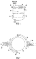
- softened water from both tanks 1 or 2 enters the meter 16 and passes through the metering chamber 40.
- This metering chamber contains a piston type water meter which measures accurately the volume of water passing through to the outlet pipe 17.
- the meter chamber drives the service meter cam 41 via a series of gears 42.
- One rotation of the service meter cam is equivalent to the pre-set volume of water that may be softened by both resin tanks.
- the blade 24 wipes past the lever blade 43 and closes the service meter valve 'locking in' the water pressure to the shuttle valve port 31.
- the volume of water required to wipe the blades past each other is less than the pre-set volume of water required to regenerate a resin tank.
- Service lever 45 operates service valve 27 and starts the regeneration of resin tank 1.
- service lever 50 with blade 51 operates service valve 28 and applies a pressure signal to shuttle valve port 32 to start the regeneration of resin tank 2.
- the lever blades 44 and 45 are positioned at 180 degrees to each other, therefore, the regeneration of either tank is 50% of the pre-set volume of one rotation of the service meter cam.
- the pre-set volume may be altered by changing the ratio of the gear chain between the meter chamber and the service cam.
- the regeneration meter 23 measures the pre-set volume of softened water and brine necessary to regenerate either resin tank 1 or 2. After the pre-set volume of regeneration water with brine has passed through the meter it stops the regeneration.
- softened water enters the metering chamber 61 of the regeneration meter 23 and flows through the metering chamber 61.
- This chamber again contains a piston type water meter which accurately measures the volume of water passing through the meter chamber.
- the meter chamber drives the regeneration cam 62 via a series of gears 63.
- Half a rotation of the regeneration meter cam is equivalent to the pre-set volume of water with entrained brine necessary to regenerate one resin tank.
- the regeneration meter cam 62 is positioned so that regeneration lever 64 is 'free' and therefore regeneration valve 29 is closed. This 'locks in' the pressure signal from the service valve 27 which opens drain shuttle valve port 31.
- the regeneration meter cam has pushed open the regeneration valve 30 via lever 65, this prevents resin tank 2 from regenerating at the same time as resin tank 1 by venting any pressure signal to drain shuttle valve port 32.
- Regeneration lever 64 operates regeneration valve 29 and stops the regeneration of resin tank 1.
- Regeneration lever 65 operates regeneration valve 30 and stops the regeneration of resin tank 2.
- the lever blades are positioned at 180 degrees to each other, therefore the volume of regeneration water with brine for each tank is 50% of the pre-set water volume necessary to rotate the regeneration cam once.
- the pre-set volume may be altered by changing the gear ratio between the meter chamber and the regeneration cam.
- the shuttle valve 11 distributes inlet water equally between resin tanks 1 and 2 when both tanks are in service, and diverts hard water to either resin tank 1 or 2 during regeneration. It also enables regeneration water from either resin tank 1 or 2 to flow to drain where such water volume is preferably measured by the regeneration meter 23.
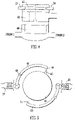
- the shuttle valve 11 comprises a housing defining chambers connected to the respective resin tanks.
- a shuttle 72 is mounted in the housing. it comprises a spindle with two pistons 75 and 76 at its ends and a central valve member.
- the shuttle 72 9 is held in a central position by the springs 73 and 74 which are of equal strength and oppose each other.
- the regeneration of resin tank 1 is started by a water pressure signal from the service valve 27 which opens drain shuttle 70.
- the path of water to flow to drain is now open, the flow of water to drain now pushing across piston 75 and closing the valve seal on its seat. Hard water can only now flow to resin tank 1 for softening.
- the regeneration water now flows from resin tank 1 past piston 75 through the open drain shuttle and then to drain.
- regeneration valve 1 opens the water pressure signal opening drain shuttle 70 is vented to draw in allowing water pressure to push drain shuttle 70 back to the closed position which equalises the water pressure in resin tanks 1 and 2 enabling the shuttle to return to a central service position; hard water again now flows to both resin tanks, that is the shuttle valve has returned to its service position.
- the regeneration of resin tank 2 is the same operation but uses drain shuttle 71 and piston 76 etc.
- softened water fills the brine tank 18 via the brine valve 19 until shut off by the brine valve float 80 to a level above the platform 81.
- the salt 82 is gradually dissolved in the water producing brine.
- Brine continues to be sucked from the brine tank until the brine level stops filling when it reaches the height of the walls of a cup-shaped weir 85.
- the level continues to fall in the weir chamber 84 until it reaches a point which enables the upper seal 85 to check shut and no more brine is sucked from the brine tank.
- Water continues to flow through the injector to flush any brine to drain from the resin tank.
- the amount of brine being capable of being sucked from the brine tank may be adjusted by raising or lowering the brine valve relative to the weir. This raises or lowers the shut off point of the water refilling the brine tank, thus adjusting the volume of brine.
- weir 85 is optional.
- Alternative means may be provided for adjustment of the water shut-off point or this point could be fixed rather than adjustable.
- service valve 27 opens and a pressure water signal is delivered to drain shuttle 70, opening it.
- the open drain shuttle 70 opens a path for water to flow to the drain.
- Water in chamber 9 pushes the shuttle 72 across a shown in Figure 3 , stopping hard water flow to resin tank 1. All hard water flow is directed to resin tank 2 which softens all the water now passing through the softener.
- Soft water flows from pipe 17 to the injector 21 which sucks brine from the brine tank via the brine valve.
- the brine solution passes through the regeneration check valve 25 and into the top of resin tank 1.
- Service check valve 14 closes, stopping softened water from resin tank 2 from entering resin tank 1.
- the brine solution flows down through resin tank 1 and regenerates the cation ion exchange resin in the resin tank.
- the brine solution then passes through chamber 9 and then via the regeneration meter 23 to drain.
- service valve 28 opens and a pressure water signal is directed to drain shuttle 71, opening it.
- the open drain shuttle 71 opens a path for water to flow to the drain.
- Water in chamber 70 pushes the shuttle 72 across as shown in Figure 1 , stopping hard water flow to resin tank 1. All hard water flow is directed to resin tank 1 which softens all the water now passing through the softener.
- Soft water flows from pipe 17 to the injector 21 which sucks brine from the brine tank via the brine valve.
- the brine solution passes through the regeneration check valve 26 and into the top of 12 resin tank 2.
- Service check valve 15 closes, stopping softened water from resin tank 1 from entering resin tank 2.
- the brine solution flows down through resin tank 1 and regenerates the cation ion exchange resin in the resin tank.
- the brine solution then passes through chamber 10 and then via the regeneration meter 23 to drain.
- the invention provides a water softener apparatus comprising two water softener tanks one of which is always operating, valves controlling the flow of water and a flow-meter, wherein, after a set volume of water has passed through one tank, water is passed through the other tank.
- the apparatus uses ion-exchange tanks which may be regenerated by brine when not softening hard water.
- the flow-meter preferably comprises an actuator which moves in a cyclic movement in response to the flow of a set quantity of water and actuates two service valves which send pressured water signals to a drain shuttle valve.
- the drain shuttle valve then diverts hard water from one tank to another and initiates regeneration of the first tank.
- a regeneration meter terminates the alternate regeneration of the two tanks.
- the regeneration meter is positioned in the apparatus downstream of a point where brine for regeneration of the two water softener components is received into the apparatus.
Landscapes
- Chemical & Material Sciences (AREA)
- Organic Chemistry (AREA)
- Chemical Kinetics & Catalysis (AREA)
- Life Sciences & Earth Sciences (AREA)
- Hydrology & Water Resources (AREA)
- Engineering & Computer Science (AREA)
- Environmental & Geological Engineering (AREA)
- Water Supply & Treatment (AREA)
- Analytical Chemistry (AREA)
- Treatment Of Water By Ion Exchange (AREA)
Claims (6)
- Eine Wasserenthärtungsvorrichtung, bestehend aus:zwei Wasserenthärtungstanks (1, 2), die jeweils ein Ionenaustauscherharz (8) zum Enthärten von Wasser enthalten, das durch die Wasserenthärtungstanks (1, 2) fließt, und die jeweils eine obere Öffnung (6) und eine untere Öffnung (6) aufweisen, wobei die unteren Öffnungen (6) der beiden Wasserenthärtungstanks (1, 2) mit den jeweiligen Kammern (9, 10) eines Wechselventils (11) verbunden sind, das eine Zufuhr von zu enthärtendem Wasser von einem Wasserversorgungsanschluss (12) des Wechselventils (11) bereitstellt, wobei das Wechselventil (11) auch eine Verbindung zum Abfluss (13) hat, wobei die oberen Öffnungen (6) der beiden Wasserenthärtungstanks (1, 2) über entsprechende Rückschlagventile (14, 15) mit einem gemeinsamen Eingang eines wasserbetriebenen Betriebszählers (16) verbunden sind, wobei ein Ausgang des wasserbetriebenen Betriebszählers (16) über eine Auslassleitung (17) für enthärtetes Wasser zu einem Auslass für enthärtetes Wasser der Wasserenthärtungsvorrichtung führt;einem Salzwassertank (18) und einem Salzwasserventil (19), das mit einer Einspritzöffnung (20) einer Einspritzvorrichtung (21) verbunden ist, die einen mit der Auslassleitung (17) für enthärtetes Wasser verbundenen Eingangsanschluss (22) und einen Auslassanschluss (24) aufweist, der über weitere jeweilige Rückschlagventile (25, 26) zu den oberen Öffnungen (6) der beiden Wasserenthärtungstanks (1, 2) führt, wobei die Einspritzvorrichtung (21) so geformt ist, dass sie bewirkt, dass Salzwasser aus dem Salzwassertank (18) in die Einspritzvorrichtung (21) gesaugt und mit enthärtetem Wasser, das aus dem Auslassanschluss (24) fließt, gemischt wird, wobei das enthärtete Wasser am Eingangsanschluss (22) der Einspritzvorrichtung (21) von der Auslassleitung (17) für enthärtetes Wasser empfangen wird;dem wasserbetriebenen Betriebszähler (16), der so konfiguriert ist, dass er zwei Betriebsventile (27, 28) steuert, die so betätigt werden können, dass sie das Wechselventil (11) steuern, um zu bewirken, dass die beiden fraglichen Wasserenthärtungstanks (1, 2) inaktiv werden, damit Wasser in jeweils unterschiedlichen Intervallen enthärtet werden kann, damit mindestens ein Wasserenthärtungstank (1, 2) die ganze Zeit über aktiv bleibt;einem Regenerationssystem zum abwechselnden Regenerieren der beiden Wasserenthärtungstanks (1, 2) während der jeweiligen unterschiedlichen inaktiven Intervalle, wobei das Regenerationssystem ein wasserbetriebenes Regenerationsmessgerät (23) enthält, das so konfiguriert ist, dass es zwei Regenerationsventile (29, 30) steuert, die so betätigt werden können, dass sie das Wechselventil (11) steuern, um die Regeneration der beiden Wasserenthärtungstanks (1, 2) während der jeweils unterschiedlichen inaktiven Intervalle zu beenden, wobei die beiden Regenerationsventile (29, 30) mit den jeweiligen Steueranschlüssen (31, 32) des Wechselventils (11) verbunden sind;wobei der wasserbetriebene Betriebszähler (16) den Strom von enthärtetem Wasser misst, der über das jeweils relevante der Betriebsventile (27, 28) zugeführt wird, sodass jedes Mal, wenn eine vorbestimmte Menge an enthärtetem Wasser zugeführt wurde, die Regeneration des jeweils relevanten der beiden Wasserenthärtungstanks (1, 2) eingeleitet wird; während der Regeneration stellt das wasserbetriebene Regenerationsmessgerät (23) über die Regenerationsventile (29, 30) zugleich die vorbestimmte Wassermenge ein, die durch den jeweils relevanten der beiden Wasserenthärtungstanks (1, 2), der gerade regeneriert wird, fließt;wobei das wasserbetriebene Regenerationsmessgerät (23) in der Vorrichtung stromabwärts vom Auslassanschluss (24) der Einspritzvorrichtung (21) angeordnet ist, wo Salzwasser für die Regeneration der beiden Wasserenthärtungstanks (1, 2) in das enthärtete Wasser eingespritzt wird, das am Eingangsanschluss (22) der Einspritzvorrichtung (21) empfangen wird, sodass das mit dem enthärteten Wasser gemischte Salzwasser zu dem jeweils relevanten der beiden Wasserenthärtungstanks (1, 2) während seines inaktiven Intervalls zur Regeneration des jeweils relevanten der beiden Wasserenthärtungstanks (1, 2) fließt und so, dass das wasserbetriebene Regenerationsmessgerät (23) ein Volumen des enthärteten Wassers einschließlich des eingespritzten Salzwassers misst, das zur Regeneration des jeweils relevanten der beiden Wasserenthärtungstanks (1, 2) verwendet wird, und in welchem nach Beendigung der Salzwassereinspritzung in das enthärtete Wasser das enthärtete Wasser weiterhin durch die Einspritzvorrichtung (21) und das wasserbetriebene Regenerationsmessgerät (23) während eines verbleibenden Zeitraums des inaktiven Intervalls der jeweils relevanten der beiden Wasserenthärtungskomponenten fließt, um jegliche Salzwasserreste aus dem wasserbetriebenen Regenerationsmessgerät (23) und dem jeweils relevanten der beiden Wasserenthärtungstanks (1, 2) zum Abfluss der Wasserenthärtungsvorrichtung zu spülen.
- Die Wasserenthärtungsvorrichtung nach Anspruch 1, wobei die beiden Betriebsventile (27, 28) und die beiden Regenerationsventile (29, 30) wasserdurchflussgesteuerte Ventile sind.
- Die Wasserenthärtungsvorrichtung nach Anspruch 1 oder Anspruch 2, wobei der wasserbetriebene Betriebszähler (16) so angeordnet ist, dass er eine abwechselnde Regeneration der beiden Wasserenthärtungstanks (1, 2) während der jeweiligen unterschiedlichen inaktiven Intervalle einleitet.
- Die Wasserenthärtungsvorrichtung nach einem der Ansprüche 1 bis 3, wobei das Regenerationsmessgerät (23) über die Verbindung zum Abfluss (13) mit dem Wechselventil (11) verbunden ist.
- Die Wasserenthärtungsvorrichtung nach einem der Ansprüche 1 bis 4, wobei der wassergetriebene Betriebszähler (16) ein bewegliches Betätigungselement aufweist, das für eine zyklische Bewegung als Reaktion auf den Fluss einer vorbestimmten Menge an enthärtetem Wasser angeordnet ist, die von einem der beiden Wasserenthärtungstanks (1, 2) zugeführt wird, wobei die beiden Regenerationsventile (29, 30) durch das Betätigungselement an den jeweiligen unterschiedlichen Positionen in seinem Bewegungszyklus betätigt werden, wobei die beiden Regenerationsventile (29, 30) zur Einleitung der Regeneration aktiv werden, wenn sie auf diese Weise betätigt wurden.
- Die Wasserenthärtungsvorrichtung nach einem der Ansprüche 1 bis 4, wobei das Regenerationsmessgerät (23) ein bewegliches Betätigungselement aufweist, das für eine zyklische Bewegung als Reaktion auf den Fluss einer vorbestimmten Menge an enthärtetem Wasser angeordnet ist, die von einem der beiden Wasserenthärtungstanks (1, 2) zugeführt wird, wobei die beiden Regenerationsventile (29, 30) durch das Betätigungselement an den jeweiligen unterschiedlichen Positionen in seinem Bewegungszyklus betätigt werden, wobei die beiden Regenerationsventile (29, 30) zur Beendigung der Regeneration aktiv werden, wenn sie auf diese Weise betätigt wurden.
Applications Claiming Priority (1)
| Application Number | Priority Date | Filing Date | Title |
|---|---|---|---|
| GB1807582.0A GB2573548B (en) | 2018-05-10 | 2018-05-10 | Water softener apparatus |
Publications (2)
| Publication Number | Publication Date |
|---|---|
| EP3567010A1 EP3567010A1 (de) | 2019-11-13 |
| EP3567010B1 true EP3567010B1 (de) | 2022-10-19 |
Family
ID=62623207
Family Applications (1)
| Application Number | Title | Priority Date | Filing Date |
|---|---|---|---|
| EP19168824.1A Active EP3567010B1 (de) | 2018-05-10 | 2019-04-12 | Wasser-weichspulergerat |
Country Status (6)
| Country | Link |
|---|---|
| US (1) | US11286180B2 (de) |
| EP (1) | EP3567010B1 (de) |
| CA (1) | CA3042210A1 (de) |
| DK (1) | DK3567010T3 (de) |
| ES (1) | ES2932090T3 (de) |
| GB (1) | GB2573548B (de) |
Families Citing this family (1)
| Publication number | Priority date | Publication date | Assignee | Title |
|---|---|---|---|---|
| JP7757640B2 (ja) * | 2021-06-23 | 2025-10-22 | 栗田工業株式会社 | 水処理システムの運転方法 |
Family Cites Families (13)
| Publication number | Priority date | Publication date | Assignee | Title |
|---|---|---|---|---|
| US3396845A (en) * | 1964-06-18 | 1968-08-13 | June S Bouskill | Water conditioning system |
| US3509998A (en) * | 1966-05-19 | 1970-05-05 | William H Pellett | Automatic regenerating apparatus for water softener |
| US3891552A (en) * | 1974-04-12 | 1975-06-24 | William C Prior | Control valve for water softeners |
| US4539106A (en) * | 1983-12-02 | 1985-09-03 | Charles E. Cates | System and apparatus for water conditioning |
| US5273070A (en) | 1989-10-05 | 1993-12-28 | Culligan International Company | Water treatment apparatus |
| US5310488A (en) * | 1991-03-01 | 1994-05-10 | Kinetico Incorporated | Water treatment method |
| DE4300585C2 (de) | 1993-01-13 | 1994-12-15 | Rudolf Schenk | Flüssigkeitsaufbereitungsanlage |
| GB2362114B (en) * | 2000-05-09 | 2004-01-21 | Kinetico Ltd | Water treatment apparartus |
| JP4182274B2 (ja) * | 2001-06-26 | 2008-11-19 | 三浦工業株式会社 | 軟水化装置 |
| JP4507270B2 (ja) * | 2001-06-26 | 2010-07-21 | 三浦工業株式会社 | 軟水化装置およびその再生制御方法 |
| CN200955032Y (zh) * | 2006-01-16 | 2007-10-03 | 宫卓立 | 全自动水处理装置 |
| US8758628B2 (en) * | 2007-10-09 | 2014-06-24 | Culligan International Company | Sensor assembly for controlling water softener tanks |
| CA2707294C (en) * | 2010-05-19 | 2019-03-19 | Kinetico Incorporated | Low water pressure operated water treatment system |
-
2018
- 2018-05-10 GB GB1807582.0A patent/GB2573548B/en active Active
-
2019
- 2019-04-12 DK DK19168824.1T patent/DK3567010T3/da active
- 2019-04-12 EP EP19168824.1A patent/EP3567010B1/de active Active
- 2019-04-12 ES ES19168824T patent/ES2932090T3/es active Active
- 2019-05-03 CA CA3042210A patent/CA3042210A1/en active Pending
- 2019-05-09 US US16/408,049 patent/US11286180B2/en active Active
Also Published As
| Publication number | Publication date |
|---|---|
| DK3567010T3 (da) | 2022-12-19 |
| EP3567010A1 (de) | 2019-11-13 |
| ES2932090T3 (es) | 2023-01-11 |
| CA3042210A1 (en) | 2019-11-10 |
| GB201807582D0 (en) | 2018-06-27 |
| US20190345043A1 (en) | 2019-11-14 |
| GB2573548A (en) | 2019-11-13 |
| GB2573548B (en) | 2022-07-06 |
| US11286180B2 (en) | 2022-03-29 |
Similar Documents
| Publication | Publication Date | Title |
|---|---|---|
| CA1165905A (en) | Water softener control | |
| US5589058A (en) | Apparatus for treatment of water | |
| US5310488A (en) | Water treatment method | |
| EP1844693B1 (de) | Verbesserte Vorrichtung zur Zuführung und Aufbereitung von Wasser für eine Geschirrspülmaschine | |
| CA1089127A (en) | Volume and time of day control for water softener regeneration | |
| EP1160204B1 (de) | Wasseraufbereitung | |
| US11286180B2 (en) | Water softener apparatus | |
| US20170217797A1 (en) | Automatic brine retrofit for a water softener system | |
| US4889623A (en) | Brining system | |
| MX2014002451A (es) | Sistema de tratamiento de agua. | |
| JP2018520280A5 (de) | ||
| US11655904B1 (en) | Valve control system | |
| US3616920A (en) | Water softener valve device | |
| US3951802A (en) | Water softener | |
| EP3722261A2 (de) | Ein wasserenthärtungsgerät | |
| DE3410826C2 (de) | Niveauregel- und Sicherheitsvorrichtung für Geschirrspül- und Waschmaschinen | |
| KR200314231Y1 (ko) | 액체 약품 자동투입기 | |
| US6287457B1 (en) | Water treatment device having volumeter driven monitoring discs | |
| US7373949B2 (en) | Fluid treatment system | |
| US2050966A (en) | Water softener | |
| EP0803473B1 (de) | Verfahren und Vorrichtung zur Behandlung von Wasser | |
| EP3732335A1 (de) | Kombinierte spül- und fülleinheit sowie verfahren zu deren betrieb | |
| US1731526A (en) | Automatic water softener | |
| US1625198A (en) | Automatic water softener | |
| US2753933A (en) | Water softener |
Legal Events
| Date | Code | Title | Description |
|---|---|---|---|
| PUAI | Public reference made under article 153(3) epc to a published international application that has entered the european phase |
Free format text: ORIGINAL CODE: 0009012 |
|
| STAA | Information on the status of an ep patent application or granted ep patent |
Free format text: STATUS: THE APPLICATION HAS BEEN PUBLISHED |
|
| AK | Designated contracting states |
Kind code of ref document: A1 Designated state(s): AL AT BE BG CH CY CZ DE DK EE ES FI FR GB GR HR HU IE IS IT LI LT LU LV MC MK MT NL NO PL PT RO RS SE SI SK SM TR |
|
| AX | Request for extension of the european patent |
Extension state: BA ME |
|
| STAA | Information on the status of an ep patent application or granted ep patent |
Free format text: STATUS: REQUEST FOR EXAMINATION WAS MADE |
|
| 17P | Request for examination filed |
Effective date: 20200314 |
|
| RBV | Designated contracting states (corrected) |
Designated state(s): AL AT BE BG CH CY CZ DE DK EE ES FI FR GB GR HR HU IE IS IT LI LT LU LV MC MK MT NL NO PL PT RO RS SE SI SK SM TR |
|
| STAA | Information on the status of an ep patent application or granted ep patent |
Free format text: STATUS: EXAMINATION IS IN PROGRESS |
|
| 17Q | First examination report despatched |
Effective date: 20201020 |
|
| GRAP | Despatch of communication of intention to grant a patent |
Free format text: ORIGINAL CODE: EPIDOSNIGR1 |
|
| STAA | Information on the status of an ep patent application or granted ep patent |
Free format text: STATUS: GRANT OF PATENT IS INTENDED |
|
| INTG | Intention to grant announced |
Effective date: 20220812 |
|
| GRAS | Grant fee paid |
Free format text: ORIGINAL CODE: EPIDOSNIGR3 |
|
| GRAA | (expected) grant |
Free format text: ORIGINAL CODE: 0009210 |
|
| STAA | Information on the status of an ep patent application or granted ep patent |
Free format text: STATUS: THE PATENT HAS BEEN GRANTED |
|
| AK | Designated contracting states |
Kind code of ref document: B1 Designated state(s): AL AT BE BG CH CY CZ DE DK EE ES FI FR GR HR HU IE IS IT LI LT LU LV MC MK MT NL NO PL PT RO RS SE SI SK SM TR |
|
| RBV | Designated contracting states (corrected) |
Designated state(s): AL AT BE BG CH CY CZ DE DK EE ES FI FR GR HR HU IE IS IT LI LT LU LV MC MK MT NL NO PL PT RO RS SE SI SK SM TR |
|
| REG | Reference to a national code |
Ref country code: CH Ref legal event code: EP |
|
| REG | Reference to a national code |
Ref country code: DE Ref legal event code: R096 Ref document number: 602019020713 Country of ref document: DE |
|
| REG | Reference to a national code |
Ref country code: IE Ref legal event code: FG4D |
|
| REG | Reference to a national code |
Ref country code: AT Ref legal event code: REF Ref document number: 1525463 Country of ref document: AT Kind code of ref document: T Effective date: 20221115 |
|
| REG | Reference to a national code |
Ref country code: NL Ref legal event code: FP |
|
| REG | Reference to a national code |
Ref country code: DK Ref legal event code: T3 Effective date: 20221215 |
|
| REG | Reference to a national code |
Ref country code: SE Ref legal event code: TRGR |
|
| REG | Reference to a national code |
Ref country code: ES Ref legal event code: FG2A Ref document number: 2932090 Country of ref document: ES Kind code of ref document: T3 Effective date: 20230111 |
|
| REG | Reference to a national code |
Ref country code: LT Ref legal event code: MG9D |
|
| REG | Reference to a national code |
Ref country code: AT Ref legal event code: MK05 Ref document number: 1525463 Country of ref document: AT Kind code of ref document: T Effective date: 20221019 |
|
| PG25 | Lapsed in a contracting state [announced via postgrant information from national office to epo] |
Ref country code: PT Free format text: LAPSE BECAUSE OF FAILURE TO SUBMIT A TRANSLATION OF THE DESCRIPTION OR TO PAY THE FEE WITHIN THE PRESCRIBED TIME-LIMIT Effective date: 20230220 Ref country code: NO Free format text: LAPSE BECAUSE OF FAILURE TO SUBMIT A TRANSLATION OF THE DESCRIPTION OR TO PAY THE FEE WITHIN THE PRESCRIBED TIME-LIMIT Effective date: 20230119 Ref country code: LT Free format text: LAPSE BECAUSE OF FAILURE TO SUBMIT A TRANSLATION OF THE DESCRIPTION OR TO PAY THE FEE WITHIN THE PRESCRIBED TIME-LIMIT Effective date: 20221019 Ref country code: FI Free format text: LAPSE BECAUSE OF FAILURE TO SUBMIT A TRANSLATION OF THE DESCRIPTION OR TO PAY THE FEE WITHIN THE PRESCRIBED TIME-LIMIT Effective date: 20221019 Ref country code: AT Free format text: LAPSE BECAUSE OF FAILURE TO SUBMIT A TRANSLATION OF THE DESCRIPTION OR TO PAY THE FEE WITHIN THE PRESCRIBED TIME-LIMIT Effective date: 20221019 |
|
| PG25 | Lapsed in a contracting state [announced via postgrant information from national office to epo] |
Ref country code: RS Free format text: LAPSE BECAUSE OF FAILURE TO SUBMIT A TRANSLATION OF THE DESCRIPTION OR TO PAY THE FEE WITHIN THE PRESCRIBED TIME-LIMIT Effective date: 20221019 Ref country code: PL Free format text: LAPSE BECAUSE OF FAILURE TO SUBMIT A TRANSLATION OF THE DESCRIPTION OR TO PAY THE FEE WITHIN THE PRESCRIBED TIME-LIMIT Effective date: 20221019 Ref country code: LV Free format text: LAPSE BECAUSE OF FAILURE TO SUBMIT A TRANSLATION OF THE DESCRIPTION OR TO PAY THE FEE WITHIN THE PRESCRIBED TIME-LIMIT Effective date: 20221019 Ref country code: IS Free format text: LAPSE BECAUSE OF FAILURE TO SUBMIT A TRANSLATION OF THE DESCRIPTION OR TO PAY THE FEE WITHIN THE PRESCRIBED TIME-LIMIT Effective date: 20230219 Ref country code: HR Free format text: LAPSE BECAUSE OF FAILURE TO SUBMIT A TRANSLATION OF THE DESCRIPTION OR TO PAY THE FEE WITHIN THE PRESCRIBED TIME-LIMIT Effective date: 20221019 Ref country code: GR Free format text: LAPSE BECAUSE OF FAILURE TO SUBMIT A TRANSLATION OF THE DESCRIPTION OR TO PAY THE FEE WITHIN THE PRESCRIBED TIME-LIMIT Effective date: 20230120 |
|
| REG | Reference to a national code |
Ref country code: DE Ref legal event code: R097 Ref document number: 602019020713 Country of ref document: DE |
|
| PG25 | Lapsed in a contracting state [announced via postgrant information from national office to epo] |
Ref country code: SM Free format text: LAPSE BECAUSE OF FAILURE TO SUBMIT A TRANSLATION OF THE DESCRIPTION OR TO PAY THE FEE WITHIN THE PRESCRIBED TIME-LIMIT Effective date: 20221019 Ref country code: RO Free format text: LAPSE BECAUSE OF FAILURE TO SUBMIT A TRANSLATION OF THE DESCRIPTION OR TO PAY THE FEE WITHIN THE PRESCRIBED TIME-LIMIT Effective date: 20221019 Ref country code: EE Free format text: LAPSE BECAUSE OF FAILURE TO SUBMIT A TRANSLATION OF THE DESCRIPTION OR TO PAY THE FEE WITHIN THE PRESCRIBED TIME-LIMIT Effective date: 20221019 Ref country code: CZ Free format text: LAPSE BECAUSE OF FAILURE TO SUBMIT A TRANSLATION OF THE DESCRIPTION OR TO PAY THE FEE WITHIN THE PRESCRIBED TIME-LIMIT Effective date: 20221019 |
|
| PLBE | No opposition filed within time limit |
Free format text: ORIGINAL CODE: 0009261 |
|
| STAA | Information on the status of an ep patent application or granted ep patent |
Free format text: STATUS: NO OPPOSITION FILED WITHIN TIME LIMIT |
|
| PG25 | Lapsed in a contracting state [announced via postgrant information from national office to epo] |
Ref country code: SK Free format text: LAPSE BECAUSE OF FAILURE TO SUBMIT A TRANSLATION OF THE DESCRIPTION OR TO PAY THE FEE WITHIN THE PRESCRIBED TIME-LIMIT Effective date: 20221019 Ref country code: AL Free format text: LAPSE BECAUSE OF FAILURE TO SUBMIT A TRANSLATION OF THE DESCRIPTION OR TO PAY THE FEE WITHIN THE PRESCRIBED TIME-LIMIT Effective date: 20221019 |
|
| 26N | No opposition filed |
Effective date: 20230720 |
|
| PG25 | Lapsed in a contracting state [announced via postgrant information from national office to epo] |
Ref country code: SI Free format text: LAPSE BECAUSE OF FAILURE TO SUBMIT A TRANSLATION OF THE DESCRIPTION OR TO PAY THE FEE WITHIN THE PRESCRIBED TIME-LIMIT Effective date: 20221019 |
|
| REG | Reference to a national code |
Ref country code: CH Ref legal event code: PL |
|
| PG25 | Lapsed in a contracting state [announced via postgrant information from national office to epo] |
Ref country code: LU Free format text: LAPSE BECAUSE OF NON-PAYMENT OF DUE FEES Effective date: 20230412 |
|
| PG25 | Lapsed in a contracting state [announced via postgrant information from national office to epo] |
Ref country code: MC Free format text: LAPSE BECAUSE OF FAILURE TO SUBMIT A TRANSLATION OF THE DESCRIPTION OR TO PAY THE FEE WITHIN THE PRESCRIBED TIME-LIMIT Effective date: 20221019 |
|
| PG25 | Lapsed in a contracting state [announced via postgrant information from national office to epo] |
Ref country code: MC Free format text: LAPSE BECAUSE OF FAILURE TO SUBMIT A TRANSLATION OF THE DESCRIPTION OR TO PAY THE FEE WITHIN THE PRESCRIBED TIME-LIMIT Effective date: 20221019 Ref country code: LI Free format text: LAPSE BECAUSE OF NON-PAYMENT OF DUE FEES Effective date: 20230430 Ref country code: CH Free format text: LAPSE BECAUSE OF NON-PAYMENT OF DUE FEES Effective date: 20230430 |
|
| PG25 | Lapsed in a contracting state [announced via postgrant information from national office to epo] |
Ref country code: BG Free format text: LAPSE BECAUSE OF FAILURE TO SUBMIT A TRANSLATION OF THE DESCRIPTION OR TO PAY THE FEE WITHIN THE PRESCRIBED TIME-LIMIT Effective date: 20221019 |
|
| PG25 | Lapsed in a contracting state [announced via postgrant information from national office to epo] |
Ref country code: BG Free format text: LAPSE BECAUSE OF FAILURE TO SUBMIT A TRANSLATION OF THE DESCRIPTION OR TO PAY THE FEE WITHIN THE PRESCRIBED TIME-LIMIT Effective date: 20221019 |
|
| PGFP | Annual fee paid to national office [announced via postgrant information from national office to epo] |
Ref country code: NL Payment date: 20250418 Year of fee payment: 7 |
|
| PGFP | Annual fee paid to national office [announced via postgrant information from national office to epo] |
Ref country code: DE Payment date: 20250422 Year of fee payment: 7 |
|
| PGFP | Annual fee paid to national office [announced via postgrant information from national office to epo] |
Ref country code: ES Payment date: 20250530 Year of fee payment: 7 |
|
| PGFP | Annual fee paid to national office [announced via postgrant information from national office to epo] |
Ref country code: IT Payment date: 20250424 Year of fee payment: 7 Ref country code: BE Payment date: 20250418 Year of fee payment: 7 |
|
| PG25 | Lapsed in a contracting state [announced via postgrant information from national office to epo] |
Ref country code: CY Free format text: LAPSE BECAUSE OF FAILURE TO SUBMIT A TRANSLATION OF THE DESCRIPTION OR TO PAY THE FEE WITHIN THE PRESCRIBED TIME-LIMIT; INVALID AB INITIO Effective date: 20190412 |
|
| PG25 | Lapsed in a contracting state [announced via postgrant information from national office to epo] |
Ref country code: HU Free format text: LAPSE BECAUSE OF FAILURE TO SUBMIT A TRANSLATION OF THE DESCRIPTION OR TO PAY THE FEE WITHIN THE PRESCRIBED TIME-LIMIT; INVALID AB INITIO Effective date: 20190412 |
|
| PG25 | Lapsed in a contracting state [announced via postgrant information from national office to epo] |
Ref country code: TR Free format text: LAPSE BECAUSE OF FAILURE TO SUBMIT A TRANSLATION OF THE DESCRIPTION OR TO PAY THE FEE WITHIN THE PRESCRIBED TIME-LIMIT Effective date: 20221019 |
|
| PGFP | Annual fee paid to national office [announced via postgrant information from national office to epo] |
Ref country code: SE Payment date: 20260212 Year of fee payment: 8 |
|
| PGFP | Annual fee paid to national office [announced via postgrant information from national office to epo] |
Ref country code: DK Payment date: 20260212 Year of fee payment: 8 Ref country code: IE Payment date: 20260212 Year of fee payment: 8 |
|
| PGFP | Annual fee paid to national office [announced via postgrant information from national office to epo] |
Ref country code: FR Payment date: 20260212 Year of fee payment: 8 |