EP3722153B1 - Improved safety device for vehicles - Google Patents
Improved safety device for vehicles Download PDFInfo
- Publication number
- EP3722153B1 EP3722153B1 EP20169124.3A EP20169124A EP3722153B1 EP 3722153 B1 EP3722153 B1 EP 3722153B1 EP 20169124 A EP20169124 A EP 20169124A EP 3722153 B1 EP3722153 B1 EP 3722153B1
- Authority
- EP
- European Patent Office
- Prior art keywords
- display
- vehicle
- mode
- driver
- view
- Prior art date
- Legal status (The legal status is an assumption and is not a legal conclusion. Google has not performed a legal analysis and makes no representation as to the accuracy of the status listed.)
- Active
Links
Images




Classifications
-
- B—PERFORMING OPERATIONS; TRANSPORTING
- B60—VEHICLES IN GENERAL
- B60R—VEHICLES, VEHICLE FITTINGS, OR VEHICLE PARTS, NOT OTHERWISE PROVIDED FOR
- B60R1/00—Optical viewing arrangements; Real-time viewing arrangements for drivers or passengers using optical image capturing systems, e.g. cameras or video systems specially adapted for use in or on vehicles
- B60R1/20—Real-time viewing arrangements for drivers or passengers using optical image capturing systems, e.g. cameras or video systems specially adapted for use in or on vehicles
- B60R1/22—Real-time viewing arrangements for drivers or passengers using optical image capturing systems, e.g. cameras or video systems specially adapted for use in or on vehicles for viewing an area outside the vehicle, e.g. the exterior of the vehicle
- B60R1/23—Real-time viewing arrangements for drivers or passengers using optical image capturing systems, e.g. cameras or video systems specially adapted for use in or on vehicles for viewing an area outside the vehicle, e.g. the exterior of the vehicle with a predetermined field of view
- B60R1/26—Real-time viewing arrangements for drivers or passengers using optical image capturing systems, e.g. cameras or video systems specially adapted for use in or on vehicles for viewing an area outside the vehicle, e.g. the exterior of the vehicle with a predetermined field of view to the rear of the vehicle
-
- B—PERFORMING OPERATIONS; TRANSPORTING
- B60—VEHICLES IN GENERAL
- B60R—VEHICLES, VEHICLE FITTINGS, OR VEHICLE PARTS, NOT OTHERWISE PROVIDED FOR
- B60R1/00—Optical viewing arrangements; Real-time viewing arrangements for drivers or passengers using optical image capturing systems, e.g. cameras or video systems specially adapted for use in or on vehicles
- B60R1/20—Real-time viewing arrangements for drivers or passengers using optical image capturing systems, e.g. cameras or video systems specially adapted for use in or on vehicles
- B60R1/22—Real-time viewing arrangements for drivers or passengers using optical image capturing systems, e.g. cameras or video systems specially adapted for use in or on vehicles for viewing an area outside the vehicle, e.g. the exterior of the vehicle
- B60R1/28—Real-time viewing arrangements for drivers or passengers using optical image capturing systems, e.g. cameras or video systems specially adapted for use in or on vehicles for viewing an area outside the vehicle, e.g. the exterior of the vehicle with an adjustable field of view
-
- H—ELECTRICITY
- H04—ELECTRIC COMMUNICATION TECHNIQUE
- H04N—PICTORIAL COMMUNICATION, e.g. TELEVISION
- H04N23/00—Cameras or camera modules comprising electronic image sensors; Control thereof
- H04N23/60—Control of cameras or camera modules
- H04N23/69—Control of means for changing angle of the field of view, e.g. optical zoom objectives or electronic zooming
-
- H—ELECTRICITY
- H04—ELECTRIC COMMUNICATION TECHNIQUE
- H04N—PICTORIAL COMMUNICATION, e.g. TELEVISION
- H04N23/00—Cameras or camera modules comprising electronic image sensors; Control thereof
- H04N23/60—Control of cameras or camera modules
- H04N23/695—Control of camera direction for changing a field of view, e.g. pan, tilt or based on tracking of objects
-
- H—ELECTRICITY
- H04—ELECTRIC COMMUNICATION TECHNIQUE
- H04N—PICTORIAL COMMUNICATION, e.g. TELEVISION
- H04N7/00—Television systems
- H04N7/18—Closed-circuit television [CCTV] systems, i.e. systems in which the video signal is not broadcast
-
- B—PERFORMING OPERATIONS; TRANSPORTING
- B60—VEHICLES IN GENERAL
- B60R—VEHICLES, VEHICLE FITTINGS, OR VEHICLE PARTS, NOT OTHERWISE PROVIDED FOR
- B60R1/00—Optical viewing arrangements; Real-time viewing arrangements for drivers or passengers using optical image capturing systems, e.g. cameras or video systems specially adapted for use in or on vehicles
- B60R1/12—Mirror assemblies combined with other articles, e.g. clocks
- B60R2001/1253—Mirror assemblies combined with other articles, e.g. clocks with cameras, video cameras or video screens
-
- B—PERFORMING OPERATIONS; TRANSPORTING
- B60—VEHICLES IN GENERAL
- B60R—VEHICLES, VEHICLE FITTINGS, OR VEHICLE PARTS, NOT OTHERWISE PROVIDED FOR
- B60R2300/00—Details of viewing arrangements using cameras and displays, specially adapted for use in a vehicle
- B60R2300/20—Details of viewing arrangements using cameras and displays, specially adapted for use in a vehicle characterised by the type of display used
- B60R2300/207—Details of viewing arrangements using cameras and displays, specially adapted for use in a vehicle characterised by the type of display used using multi-purpose displays, e.g. camera image and navigation or video on same display
-
- B—PERFORMING OPERATIONS; TRANSPORTING
- B60—VEHICLES IN GENERAL
- B60R—VEHICLES, VEHICLE FITTINGS, OR VEHICLE PARTS, NOT OTHERWISE PROVIDED FOR
- B60R2300/00—Details of viewing arrangements using cameras and displays, specially adapted for use in a vehicle
- B60R2300/40—Details of viewing arrangements using cameras and displays, specially adapted for use in a vehicle characterised by the details of the power supply or the coupling to vehicle components
- B60R2300/404—Details of viewing arrangements using cameras and displays, specially adapted for use in a vehicle characterised by the details of the power supply or the coupling to vehicle components triggering from stand-by mode to operation mode
-
- B—PERFORMING OPERATIONS; TRANSPORTING
- B60—VEHICLES IN GENERAL
- B60R—VEHICLES, VEHICLE FITTINGS, OR VEHICLE PARTS, NOT OTHERWISE PROVIDED FOR
- B60R2300/00—Details of viewing arrangements using cameras and displays, specially adapted for use in a vehicle
- B60R2300/80—Details of viewing arrangements using cameras and displays, specially adapted for use in a vehicle characterised by the intended use of the viewing arrangement
- B60R2300/8066—Details of viewing arrangements using cameras and displays, specially adapted for use in a vehicle characterised by the intended use of the viewing arrangement for monitoring rearward traffic
Definitions
- the present invention relates to an improved safety device for vehicles.
- the present invention relates to improved devices for increasing the active safety of cycles, mopeds, motorcycles and all other types of vehicles, integrating the functions of the displays and rear-view mirrors currently supplied to vehicles in general.
- the present invention provides for the adoption of special devices to integrate the functions of the displays and rear-view mirrors to allow the driver/rider to have a clear, complete and panoramic rear view, without blind spots and incorrect assessment of the distances, while the vehicle moves forward, thus increasing the active safety of bicycles, cycles, mopeds, motorcycles and all other types of vehicle in general.
- the device allows cyclists not to have to take a hand off the handlebars to manage the information of the on-board computer, all to the advantage of active safety.
- rear-view mirrors implies for the driver of a motor car the following limitations and problems which, as the case may be, are also shared by drivers of other types of vehicles:
- a video camera positioned in the rear part of the vehicle; the images taken by this camera are displayed on a display usually installed in the dashboard in a central position, also used for other functions such as displaying radio, DVD, external music sources information and for viewing map or navigator images and data, and more recently a whole range of other information or data relating to the vehicle.
- the video camera activates automatically when the driver engages the reverse gear; however, it does not work during normal forward travelling.
- This information is shown sequentially by pressing one or more buttons located in the box-like element which also contains the display.
- Cycles with pedal assistance usually have a display that permanently or sequentially displays the battery status, the level of pedal assistance required, information from the on-board computer, etc.
- Cars, buses, caravans, trucks, lorries generally are supplied with at least two displays.
- a first display is generally placed in front of the steering wheel; it displays - usually analogically - the vehicle speed, engine revolutions and other on-board computer information (instant and average consumption, total or partial mileage, etc.); some of the data or information appear sequentially by pressing a special button provided on the steering wheel, or near the steering wheel.
- this smaller-size display is interposed between the two traditional circular needle instruments, and it displays information such as instant and average consumption, total and partial mileage, etc.; also in these cases, some of the information appears sequentially by pressing a special button provided on the steering wheel or near the steering wheel.
- a second display is placed in the central part of the dashboard, generally lower than the first.
- this second display is used to alternately view:
- the technical aim of the present invention is to improve the current state of the art in the field of safety equipment for bicycles, mopeds, motorcycles and all other types of vehicles, both for newly manufactured ones and for those already in circulation, in order to increase their active safety.
- Another object of the present invention is to develop a vehicle safety device that can be adopted immediately by the manufacturers, in compliance with the regulations of the individual countries, both for newly manufactured vehicles and for those already in circulation.
- a further object of the present invention is to provide a vehicle safety device which can be activated in a simple, easy and safe way, without risks for the driver/rider.
- Yet another object of the present invention is to provide a safety device for cycles consisting in an "aftermarket” product, or installable on newly manufactured cycles, which allows cyclists not to have to take a hand off the handlebars to manage the on-board computer information, all to the advantage of active safety.
- an improved safety device for vehicles is generally indicated with 1.
- Figure 1 shows a vehicle V consisting in a car; the vehicle V could however be of any other type, for example a truck ( Figure 2 ), a bus ( Figure 3 ), or other, without any particular limitations for the purposes of the present invention.
- the device 1 comprises at least one video camera 2, or a plurality of video cameras 2a, 2b, 2c.
- the video camera 2, or each of video cameras 2a, 2b, 2c, can be of any type suitable for the application: for example, it can be a mini-video camera.
- the video camera 2, or each one of the video cameras 2a, 2b, 2c, can be installed in a portion of the outer rear surface 3 of the vehicle V, oriented so that its lens faces substantially in the direction opposite to the travelling direction of the vehicle V itself.
- the video camera 2 or each one of the video cameras 2a, 2b, 2c, is oriented so that its lens can film the surrounding environment behind the vehicle V with respect to the normal forward travelling direction.
- the device 1 which is not part of the present invention, preferably comprises a single video camera 2, installed in the rear area of the vehicle V itself.
- the single video camera 2 can be installed under the seat of vehicle V.
- the device 1 comprises one or more cameras 2a, 2b, 2c.
- the device 1 comprises at least three video cameras 2a, 2b, 2c, or even a higher number of cameras.
- the above mentioned three video cameras 2a, 2b, 2c comprise a central video camera 2a, and two side video cameras 2b, 2c.
- the central video camera 2a can be installed in the rear area of the vehicle V, preferably in the centre, and preferably in a position from which the shots are optimal: for example, it can be positioned at the top of the rear area, as shown in figures 1-3 , or possibly even lower, in the area of the plate holder.
- the central video camera 2a can have a tilt and zoom function so as to provide a more panoramic and remote view when the vehicle V is driven forward, and a more narrow and downward-directed view towards the road while the vehicle is reversing.
- the side video cameras 2b, 2c are preferably installable in positions that allow the driver to have a rear view as close as possible and comparable to that which is obtained by checking the traditional side rear-view mirrors.
- the side video cameras 2b, 2c in an embodiment of the invention of particular practical interest, can be installed in the bodywork of the vehicle V under the two side external rear-view mirrors 4.
- the side video cameras 2b, 2c do not interfere with the driver's direct side vision.
- the side video cameras 2b, 2c of device 1 could be provided in other areas of the external rear surface 3 of the vehicle V, if certain design/application requirements require it.
- the side video cameras 2b, 2c can be adjustable in position, like the current mirrors, with manual or electric devices to optimize vision on the sides according to height, and according to the needs of the driver; the side video cameras 2b, 2c could also be automatically positioned downwards when the reverse gear is engaged.
- the device 1 furthermore comprises at least one processing unit 5.
- the processing unit 5 is shown schematically with broken lines, and for the sole purpose of a better understanding, in Figure 5 .
- the single video camera 2, or the plurality of video cameras 2a, 2b, 2c, is operatively connected to, and controlled by, the processing unit 5.
- the processing unit 5 can be the same already present in the vehicle V (for example, the control unit of the vehicle V, or a specific sub-unit of the control unit), or it can be an autonomous unit, only appointed to manage the device 1 according to the invention.
- the device 1 also comprises at least one display 6.
- the display 6 is operatively connected to the processing unit 5.
- the display 6 is suitable for viewing the images taken by the single video camera 2, or by the plurality of video cameras 2a, 2b, 2c.
- the display 6 is suitable for viewing the images taken by the single camera 2, or by the plurality of video cameras 2a, 2b, 2c, when the vehicle V travels in the forward direction.
- the driver can monitor and detect the movement of the vehicles that follow them, to avoid, in turn, performing actions or movements that could put them and/or other vehicles in a situation of potential danger.
- the display 6 is positioned, in the vehicle V, so that the driver can monitor it quickly and effectively without taking their eyes off the travelling direction for too long.
- the display 6 is positioned inside the instrument panel 7 of the vehicle V, in a front position with respect to the driving position.
- the display 6 is provided in the middle of the instrument panel 7; in this position, the display 6 can be immediately viewed by the driver of the vehicle V by simply lowering their gaze slightly from the travelling direction, for even just a few seconds.
- the dimensions of the display 6 are such as to allow the driver to have a clear, sharp and complete view, compatibly with the space available inside the instrument panel 7.
- V vehicles equipped with large instrument panels 7 are advantaged from this point of view.
- the display 6 is as large as possible, precisely for the driver needing to have a clear, sharp and full vision while driving.
- the display 6 is a display already supplied to the vehicle V; therefore, there is no need to provide another special display.
- the device 1 comprises a control 8.
- the control 8 is operatively connected to the processing unit 5.
- the control 8 can be operated by the driver at their own discretion, and is suitable for activating the video camera 2 (or the plurality of video cameras 2a, 2b, 2c), and therefore the rear view function, in real time, on the display 6.
- control 8 is suitable for selectively modifying, at the discretion of the driver of the vehicle V, the mode of use of the display 6 from a first mode, wherein the rear display function is not active, to a second mode, wherein the rear display function is active, and vice versa.
- the display 6 works like a traditional display, i.e., it shows the normal information relating to the vehicle, and possibly also graphics and/or images, if it is provided to operate in this way (for example, images or graphics of the navigator, of the radio, or even images or graphics that simulate analog instruments, etc.).
- the display 6 is controlled for viewing, in real time, the images taken by the single video camera 2, or by the plurality of video cameras 2a, 2b, 2c.
- the control 8 can be of the manually operated type; the control 8 can consist, for example, of a button, a lever, a knob or the like.
- the control 8 can comprise (or consist of) a button (or lever, or knob) located on the steering wheel 9, for example on the spokes of the steering wheel 9 ( figure 5 ), or also on the inside of the wheel of the steering wheel, or near it.
- the driver can change the way the display 6 is used quickly and easily even without taking their eyes off the driving i.e. the travelling direction.
- the driver wishes to overtake, or change lanes, they can then operate the control 8 to activate, even if only for a few moments, the rear view, so as to ensure that there are no approaching vehicles and that there is sufficient space and the necessary safety conditions.
- the control 8 can be configured so as to allow the operating mode to be changed (in particular changing from the first mode to the second mode, in which the rear view is active) only when the driver actively works it: for example, in the event that the control 8 is a button, this means that the rear display is activated only when the driver holds down the aforesaid button (and it is therefore deactivated when the button is released).
- control 8 can be configured so as to allow the operating mode to be changed (from first to second, and vice versa) through a simple press or touch.
- control 8 is a button
- driver may choose/set their preferred configuration of use of the control 8 (simple press, press and hold, etc.).
- the device 1 can also comprise several actuation controls 8, to make the driver's gestures easier (for example, two identical and symmetrical buttons on the steering wheel 9 in the case of a vehicle consisting of a car, truck, bus, etc.).
- actuation controls 8 for example, two identical and symmetrical buttons on the steering wheel 9 in the case of a vehicle consisting of a car, truck, bus, etc.
- the actuation control 8 can also be of the non-manual type.
- control 8 could be of the vocal type, or of another type, without any particular limitations to the purposes of the present invention.
- FIG. 6 The embodiment of the invention illustrated in detail in Figures 6,7 refers, in particular, to a vehicle V of the type of cars, trucks, buses, etc., comprising an instrument panel 7 entirely consisting of a single display 6 (for example of the LCD type or the like), which in the first mode of use ( figure 6 ) shows, on a full screen, parameters and information relating to the vehicle, as well as graphics and images (images of the navigator, and/or emulation of analog instruments, and/or other).
- a single display 6 for example of the LCD type or the like
- graphics and images images of the navigator, and/or emulation of analog instruments, and/or other.
- the display 6 allows rear images to be displayed taken by the video cameras 2a, 2b, 2c.
- the display 6 comprises at least three rear display portions 6a, 6b, 6c side by side, i.e. one central portion 6a and two side portions 6b, 6c, which show, in real time, the images taken by the three video cameras 2a, 2b, 2c, respectively.
- the instrument panel 7 is entirely made up of a single display 6, the three rear display portions 6a, 6b, 6c can have an overall surface that substantially corresponds to the entire surface of the display 6 (possibly, subject to minor differences due to the shape of the instrument panel 7 itself).
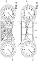
- the embodiment of the invention illustrated in detail in Figures 8,9 refers, instead, to a vehicle V of the type of cars, trucks, buses, etc. equipped with a more traditional type of instrument panel 7, comprising at least one analog instrument 10a, 10b.
- the embodiment of Figures 8,9 includes, more particularly, two analog instruments 10a, 10b (typically, but not exclusively, an odometer and a tachometer) between which at least one display 6 is comprised.
- the aforementioned display 6, in the first mode of use shows parameters and information relating to the vehicle, and/or graphics and images (images of the navigation system, and/or simulation of analog instruments, and/or other).
- the display 6 allows rear images to be displayed, taken by the video cameras 2a, 2b, 2c.
- the display 6 comprises three rear display portions 6a, 6b, 6c side by side, i.e. a central portion 6a and two side portions 6b, 6c.
- the instrument panel 7 is entirely made up of a single display 6 (similarly to the embodiment of Figures 6,7 ).
- the device 1 comprises, as was said, a single video camera 2; consequently, the display 6 also comprises a single rear display portion (which therefore may have a surface substantially corresponding to that of the entire display 6).
- Figure 10 refers to the first mode of use of the display 6, wherein the display works in the traditional way, showing data, parameters, graphics relating to the vehicle.
- Figure 11 refers instead to the second mode of use of the display 6, wherein the display shows, in real time and on full screen, the images taken by the single video camera 2.
- the control 8, in this embodiment of the device 1, can comprise (or consist of) at least one button associated with the handlebar 11 of the motorcycle V.
- the rider while riding, if they want to activate the rear display function, activates the control 8 (for example, by pressing the button on the handlebars 11), and thus determining the shifting of the display 6 from the first mode of use ( Figure 10 ) to the second mode of use ( Figure 11 ).
- the configuration of the control 8 can be of the active actuation type (i.e. the second mode of use is active only as long as the control 8 is actually activated) or with actuation determined by a single touch to activate/deactivate the second mode of use.
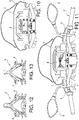
- the vehicle V which incorporates the device 1 according to the invention can be provided with side rear-view mirrors 4 with variable configuration, in particular, foldable.
- the motorcycle V can comprise side rear-view mirrors 4 which can switch from the normal open use configuration ( Figure 12 ) to a closed configuration ( Figure 13 ), wherein they are not used, since rear vision is guaranteed by device 1.
- the embodiment illustrated in Figures 14, 15 which is not part of the invention, refers to a device 1 installed on a motorcycle V (of a different type from that of the embodiment of Figures 10, 11 ).
- the instrument panel 7 comprises at least one analog instrument 10a, 10b; in more detail, this instrument panel 7 comprises two analog instruments 10a, 10b (typically an odometer and a tachometer) between which at least one display 6 is included.
- the device 1 comprises a single rear video camera 2; consequently, the display 6 also comprises a single rear viewing portion (which therefore may have a surface substantially corresponding to that of the entire display 6).
- Figure 14 refers to the first mode of use of the display 6, wherein the display works in the traditional way, showing data, parameters, graphics relating to the vehicle.
- Figure 15 refers, instead, to the second mode of use of the display 6, wherein the display shows, in real time, the images taken by the single video camera 2, thus allowing for displaying the rear view from the motor cycle V.
- control 8 can comprise (or consist of) at least one button associated with the handlebars 11 of the motorcycle V.
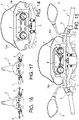
- the motorcycle V can be provided with side mirrors 4 with variable configuration.
- the side rear-view mirrors 4 can be movable from a normal configuration of use ( Figure 16 ), to a configuration of low drag ( Figure 17 ), wherein they are - for example - rotated so as to be arranged to be substantially parallel to the horizontal plane.
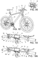
- the vehicle V comprising the device 1 is a cycle, or bicycle.
- This embodiment can be indicated for newly manufactured cycles V; however, the entire device 1 can consist of a complete kit that can be installed on any cycle V. More specifically, the video camera 2 can be associated with a respective bracket 12, or another equivalent support element, which can be fixed to the rear part of the frame 13 of the cycle V.
- the device 1 can comprise an instrument panel 7 which comprises a box-like element 14 which can be fixed to the handlebars 15 of the cycle V.
- the box-like element 14 can be fixed to the handlebar 15 by means of clamps 16, which can be of any suitable type.
- the processing unit 5 is housed inside the box-like element 14; moreover, the box-like element 14 houses the display 6.
- the box-like element 14 can comprise buttons 17 for controlling the viewing functions of the display 6, in particular in its first mode of use.
- the control 8 comprises an element 18 for fixing to the handlebar 15 of the bicycle V.
- the fixing element 18 can consist, for example, of a ring, a clamp, or the like.
- the control 8 can comprise a first button or a lever 8a, adapted to activate/deactivate the second mode of use of the display 6, associated with the fixing element 18.
- control 8 can comprise a second button 8b for controlling the viewing functions of the display 6 in its first mode of use.
- the second button 8b is also integrated in the same fixing element 18.
- the second button 8b allows the cyclist to select the various pieces of information to be displayed sequentially, without taking their hands off the handlebars 15.
- first button 8a and the second button 8b are associated with a first fixing element 18a and a second fixing element 18b - respectively, provided near the two opposite handles of the handlebars 15.
- the cyclist can, with one hand (via the first button 8a) control the transition from the first mode to the second mode of use of the display 6, and vice versa; they can also, with the other hand (via the second button 8b), select the information to be displayed sequentially, forward or backward.
- the cyclist can avoid pressing the control buttons 17 on the display to view different information.
- the various components of the device 1 - in particular the box-like element 14, the video camera 2 and the control 8 - can be connected by cables 19 fixed along various parts of the frame 13 or of the handlebars 15.
- Figure 19 refers to the first mode of use of the display 6, wherein the display works in the traditional way, showing data, parameters, graphics relating to the vehicle.
- Figure 20 refers instead to the second mode of use of the display 6, wherein the display shows, in real time, the images taken by the single video camera 2, thus allowing the rear view from the cycle V to be displayed.
- the configuration of the control 8 can be of the active actuation type (i.e. the second mode of use is active only as long as the control 8 is actually activated) or with actuation determined by a single touch to activate/deactivate the second mode of use.
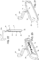
- Figures 21-27 refer to embodiments wherein the device 1 comprises a support 20 with which the display 6 is associated; this support 20 also includes at least one mirror 21, which can be used as a rear-view mirror.
- the display 6 and the mirror 21 can be used alternatively one to the other: in particular, the mirror 21 can be used in case of failure of the display 6, or of the video camera 2, or of other parts of the device 1.
- the support 20 comprises an element 22 having a first surface 23, wherein the display 6 is provided.
- the element 22 further comprises a second surface 24, opposed to the first surface 23, wherein the rear-view mirror 21 is provided.
- Figures 21-23 concern an embodiment, which is not part of the invention, wherein the support 20 can be installed inside the passenger compartment of a vehicle V such as a car, a truck, a bus, etc., in place of the normal central rear-view mirror.
- a vehicle V such as a car, a truck, a bus, etc.
- the support 20 can replace the normal central rear-view mirror in vehicles V (typically cars) in which it is present; in vehicles V where, instead, it is not normally present (for example trucks, buses, etc.) the support 20 could be newly installed.
- the element 22 of the support 20 When viewed from the front, and also from the side - see for example Figure 22 - the element 22 of the support 20 has essentially the same footprint as a normal central rear-view mirror for the passenger compartment of cars, or the like.
- the support 20 further comprises a connecting portion 25 of the element 22 to fixed parts of the vehicle V; in more detail, the connecting portion 25 is suitable for binding the element 22, for example, to the roof of the passenger compartment of the vehicle V.
- connections 25a of the display 6 to the processing unit 5 can go through the connecting portion 25.
- the support 20 comprises a rotating joint 26, which connects the element 22 to the connecting portion 25.
- the rotating joint 26 allows the element 22 to be rotated manually with respect to the connecting portion 25, so as to selectively orient the first surface 23, or the second surface 24, towards the driver.
- the driver orients the first surface 23, comprising the display 6, so that it can be observed during the forward travelling of the vehicle V.
- the driver does not intend to monitor the rear area of the vehicle V via the display 6, or, and most notably, in the event of failure of some component of the device 1 (for example the display 6 itself, or one of the video cameras 2a, 2b, 2c) the driver can manually rotate the element 22 around the rotating joint 26, so as to orient towards themselves the second surface 24, comprising the rear-view mirror 21.
- the driver can continue to monitor the rear area, albeit with the traditional rear-view mirror vision.
- the display 6 comprises three rear viewing portions 6a, 6b, 6c side by side, i.e. a central portion 6a and two side portions 6b, 6c, which display the images taken by the central video camera 2a and by the side video cameras 2b, 2c of vehicle V - respectively.
- control 8 is configured to selectively activate or deactivate the rear display function in the support 20, since the display 6 is solely assigned to this function.
- FIGs 24,25 another embodiment, which is not part of the invention, is schematically represented, with characteristics similar to those of the embodiment of Figures 21-23 , wherein the vehicle V consists in a motorbike, a moped, or the like. Also in this embodiment, the vehicle V comprises, in place of at least one of the traditional rear-view mirrors 21 (in particular, at least the right one), at least one support 20 having characteristics similar to those described with regard to the embodiment of Figures 21-23 .
- this embodiment of the invention includes one additional feature, namely the fact that the support 20 includes at least one protection 27 for one or the other of the surfaces 23,24 of the element 22.
- the surface 23,24 which is positioned forward can become dirty, wet or damaged.
- the protection 27 can therefore be removed (fixed for example by interlocking portions 27a or other similar fixing means) so that it can be easily assembled or disassembled as may be necessary, at one or the other of the surfaces 23,24.
- control 8 is configured to selectively activate or deactivate the rear viewing function in the display 6 of the support 20.
- Figures 26, 27 is similar to that of Figures 24, 25 , and differs in that the vehicle V is constituted here by a cycle.
- the device 1 can comprise a box-like element 14, to which all the components of the device 1 are operatively connected (for example by means of cables 19).
- the box-like element 14 also houses the processing unit 5; the same box-like element 14 can also comprise push buttons 17 for the main control/adjustment operations of the device 1.
- the box-like element 14 can be fixed, for example, to the handlebar 15 of the cycle V, in the most convenient and most easily accessible position.
- control 8 is configured to selectively activate or deactivate the rear viewing function in the support 20, at the rider's discretion.
- the display 6 can be of any known type, and suitable for this type of application.
- the display 6 can be of the LCD type, with limited footprint especially as regards thickness; this allows its assembly on even very thin and light supports, which do not, for example, modify the characteristics of the instrument panel 7 of vehicle V.
- the images taken by the video camera 2 or by the video cameras 2a, 2b, 2c can undergo any treatment and/or processing (carried out by the processing unit 5) before being sent to the display 6; for example, in the case of use in poor visibility conditions (low light, or fog, etc.) the images taken by the video camera 2 may undergo changes/processing (for example for characteristics such as brightness, contrast, or others) in order to be better visible for the driver.
- any treatment and/or processing carried out by the processing unit 5 before being sent to the display 6; for example, in the case of use in poor visibility conditions (low light, or fog, etc.) the images taken by the video camera 2 may undergo changes/processing (for example for characteristics such as brightness, contrast, or others) in order to be better visible for the driver.
- the video camera 2, or the video cameras 2a, 2b, 2c can also be used to facilitate reversing operations, as already happens in some vehicles; in this case, the images taken can be sent - as already happens - to the central display provided on the vehicle's dashboard.
- An object of the present invention is also a vehicle V comprising a safety device 1 having the characteristics described above.
- an object of the present invention is a vehicle V consisting of a car, a truck, a bus, , or others, comprising the device 1 according to the present invention.
- the invention thus conceived, allows to obtain important technical advantages.
- the main advantage of the device 1 according to the present invention is constituted by clear, sharp and complete rear vision during forward travelling of the vehicle V, especially in the case in which the use of traditional rear-view mirrors is hindered or made difficult for some reason (for example, due to the presence of passengers or bulky luggage on vehicle V).
- Another advantage consists in the fact that the actuation of the device 1, to activate the rear viewing function at a given moment, is carried out through a very simple and easy control 8 (for example, but not exclusively, manually), which allows the driver not to take their eyes off the direction of travel.
- Another advantage consists in the fact that the device 1, in embodiments which are not according to the invention and which are present for illustration purposes only, can be easily integrated/incorporated into elements or components already provided in the vehicle V; we refer in particular to the embodiments of Figures 21-27 , wherein the support 20 of the device 1 itself completely replaces at least one of the traditional rear-view mirrors, and does not imply further additional footprint.
- the device 1 allows the driver of the vehicle V to have a full rear view both in normal forward travelling and during reversing operations, thus making the installation of the devices in use today - which are often supplied as options - unnecessary for viewing rear view images in a monitor during reversing operations only.
- the adoption of the device 1 which is an object of the present invention would also allow vehicle (for example car) designers to design the bodywork of the rear part of the vehicle without the current constraints in the sizing of the rear pillars or of the rear window to make it possible for the driver to have a rear view through the interior rear-view mirror.
- vehicle for example car
- the driver in order to have rear vision, the driver must take their eyes and attention away from the travelling direction of the vehicle for an extremely short period of time, since the images taken by the various cameras are displayed in a single display.
- the newly manufactured vehicles could be equipped from the start with the devices provided in the present invention, so as to be able to eliminate the side mirrors and the internal central mirror, with all the advantages already mentioned, as soon as the legislation of each individual country allows it.
- the external and internal mirrors could be arranged to be disassembled, and the fixing and routing holes of any cables could be closed with practical and special pre-supplied covers.
- the external mirrors should have a good aerodynamic profile both in the open and closed position, so as to minimize drag in the event that a first regulatory change may allow vehicles equipped with mini-cameras to travel with the external mirrors closed and the internal one raised, subject to their repositioning only in case of malfunction of the display and/or mini-cameras.
Landscapes
- Engineering & Computer Science (AREA)
- Multimedia (AREA)
- Mechanical Engineering (AREA)
- Signal Processing (AREA)
- Closed-Circuit Television Systems (AREA)
- Fittings On The Vehicle Exterior For Carrying Loads, And Devices For Holding Or Mounting Articles (AREA)
- Electrical Discharge Machining, Electrochemical Machining, And Combined Machining (AREA)
- Burglar Alarm Systems (AREA)
- Vehicle Waterproofing, Decoration, And Sanitation Devices (AREA)
- Vehicle Step Arrangements And Article Storage (AREA)
Applications Claiming Priority (1)
| Application Number | Priority Date | Filing Date | Title |
|---|---|---|---|
| IT102019000005598A IT201900005598A1 (it) | 2019-04-11 | 2019-04-11 | Dispositivo di sicurezza perfezionato per veicoli |
Publications (2)
| Publication Number | Publication Date |
|---|---|
| EP3722153A1 EP3722153A1 (en) | 2020-10-14 |
| EP3722153B1 true EP3722153B1 (en) | 2022-05-18 |
Family
ID=67513617
Family Applications (1)
| Application Number | Title | Priority Date | Filing Date |
|---|---|---|---|
| EP20169124.3A Active EP3722153B1 (en) | 2019-04-11 | 2020-04-09 | Improved safety device for vehicles |
Country Status (6)
| Country | Link |
|---|---|
| US (1) | US11483519B2 (pl) |
| EP (1) | EP3722153B1 (pl) |
| ES (1) | ES2925629T3 (pl) |
| IT (1) | IT201900005598A1 (pl) |
| PL (1) | PL3722153T3 (pl) |
| PT (1) | PT3722153T (pl) |
Families Citing this family (7)
| Publication number | Priority date | Publication date | Assignee | Title |
|---|---|---|---|---|
| US12366855B2 (en) | 2020-02-26 | 2025-07-22 | Polaris Industries Inc. | Environment monitoring system and method for a towed recreational vehicle |
| CN115916610A (zh) * | 2020-04-21 | 2023-04-04 | 北极星工业有限公司 | 用于操作全地形车辆的系统及方法 |
| KR20220137373A (ko) * | 2021-04-02 | 2022-10-12 | 현대자동차주식회사 | 차량 제어 장치 및 방법 |
| FR3123029A1 (fr) * | 2021-05-18 | 2022-11-25 | Psa Automobiles Sa | Procédé de gestion du fonctionnement d’un appareillage de surveillance de l’environnement de conduite d’un véhicule automobile lors de la réalisation de manœuvres en marche arrière |
| EP4373076A1 (en) * | 2022-11-16 | 2024-05-22 | Volvo Truck Corporation | Activation of vehicle convoy rear cameras |
| US12162570B2 (en) * | 2023-03-30 | 2024-12-10 | Honda Motor Co., Ltd. | Display device for watercraft |
| WO2025157758A1 (en) * | 2024-01-25 | 2025-07-31 | Stoneridge Electronics Ab | Systems and methods for steering wheel-based control of camera monitor system |
Citations (1)
| Publication number | Priority date | Publication date | Assignee | Title |
|---|---|---|---|---|
| US10239456B1 (en) * | 2016-02-10 | 2019-03-26 | Ambarella, Inc. | Apparatus to adjust a field of view displayed on an electronic mirror using an automobile state or a driver action |
Family Cites Families (8)
| Publication number | Priority date | Publication date | Assignee | Title |
|---|---|---|---|---|
| JPH0891158A (ja) * | 1994-09-22 | 1996-04-09 | Shiyuuichi Takada | 自動車後方確認装置 |
| US6690268B2 (en) * | 2000-03-02 | 2004-02-10 | Donnelly Corporation | Video mirror systems incorporating an accessory module |
| US8154418B2 (en) * | 2008-03-31 | 2012-04-10 | Magna Mirrors Of America, Inc. | Interior rearview mirror system |
| US8643722B2 (en) * | 2008-10-08 | 2014-02-04 | Cerevellum Design, Llc | Rear-view display system for a bicycle |
| US8411245B2 (en) * | 2009-02-06 | 2013-04-02 | Gentex Corporation | Multi-display mirror system and method for expanded view around a vehicle |
| CA2726186C (en) * | 2009-12-22 | 2018-01-02 | Marc Robert | Side mirror system with video display |
| JP6077210B2 (ja) * | 2011-12-22 | 2017-02-08 | トヨタ自動車株式会社 | 車両用後方監視装置 |
| US20180154831A1 (en) * | 2016-07-29 | 2018-06-07 | Faraday&Future Inc. | Composite display from one or more cameras |
-
2019
- 2019-04-11 IT IT102019000005598A patent/IT201900005598A1/it unknown
-
2020
- 2020-04-09 PT PT201691243T patent/PT3722153T/pt unknown
- 2020-04-09 ES ES20169124T patent/ES2925629T3/es active Active
- 2020-04-09 EP EP20169124.3A patent/EP3722153B1/en active Active
- 2020-04-09 PL PL20169124.3T patent/PL3722153T3/pl unknown
- 2020-04-10 US US16/845,488 patent/US11483519B2/en active Active
Patent Citations (1)
| Publication number | Priority date | Publication date | Assignee | Title |
|---|---|---|---|---|
| US10239456B1 (en) * | 2016-02-10 | 2019-03-26 | Ambarella, Inc. | Apparatus to adjust a field of view displayed on an electronic mirror using an automobile state or a driver action |
Also Published As
| Publication number | Publication date |
|---|---|
| PT3722153T (pt) | 2022-08-09 |
| IT201900005598A1 (it) | 2020-10-11 |
| PL3722153T3 (pl) | 2022-09-19 |
| US20200329216A1 (en) | 2020-10-15 |
| US11483519B2 (en) | 2022-10-25 |
| ES2925629T3 (es) | 2022-10-19 |
| EP3722153A1 (en) | 2020-10-14 |
Similar Documents
| Publication | Publication Date | Title |
|---|---|---|
| EP3722153A1 (en) | Improved safety device for vehicles | |
| CN107791949B (zh) | 车载摄像头的hud集成集群系统 | |
| US7924506B2 (en) | Head-mounted display system | |
| US10315578B2 (en) | Modular mirror assembly | |
| US8538628B2 (en) | Control device | |
| JP4510019B2 (ja) | 車両用表示装置、車両、表示方法、画像表示プログラム、および記録媒体 | |
| EP2730449B1 (en) | Vehicular display system | |
| JP2019116222A (ja) | 車両用表示装置及び車両 | |
| US20120072103A1 (en) | Information display arrangement | |
| US20090128307A1 (en) | Display device and display method for a vehicle | |
| EP2228259A1 (en) | Sideview Vision System displaying a view dependent upon transmission selector | |
| JPH0651451B2 (ja) | 車両用表示装置 | |
| JP6949482B2 (ja) | 鞍乗型車両用の表示装置及び鞍乗型車両 | |
| WO2017124038A1 (en) | Modular mirror assembly | |
| JP5435806B2 (ja) | 車両用表示装置 | |
| JP4394228B2 (ja) | 鞍乗型車両用映像表示装置 | |
| JP2019110389A (ja) | 車両周辺監視装置 | |
| JP2013208996A (ja) | 自動二輪車におけるミラー構造 | |
| JPWO2024069692A5 (pl) | ||
| JP4784911B2 (ja) | 車両用表示装置 | |
| JP2023180240A (ja) | 自動車 | |
| KR20120016324A (ko) | 차량용 주행보조장치 | |
| US11880038B2 (en) | Hybrid vehicle projector | |
| JP2003306057A (ja) | 乗物用計器パネル | |
| JP2008044475A (ja) | 車両用周辺モニタ装置 |
Legal Events
| Date | Code | Title | Description |
|---|---|---|---|
| PUAI | Public reference made under article 153(3) epc to a published international application that has entered the european phase |
Free format text: ORIGINAL CODE: 0009012 |
|
| STAA | Information on the status of an ep patent application or granted ep patent |
Free format text: STATUS: THE APPLICATION HAS BEEN PUBLISHED |
|
| AK | Designated contracting states |
Kind code of ref document: A1 Designated state(s): AL AT BE BG CH CY CZ DE DK EE ES FI FR GB GR HR HU IE IS IT LI LT LU LV MC MK MT NL NO PL PT RO RS SE SI SK SM TR |
|
| AX | Request for extension of the european patent |
Extension state: BA ME |
|
| STAA | Information on the status of an ep patent application or granted ep patent |
Free format text: STATUS: REQUEST FOR EXAMINATION WAS MADE |
|
| 17P | Request for examination filed |
Effective date: 20210414 |
|
| RBV | Designated contracting states (corrected) |
Designated state(s): AL AT BE BG CH CY CZ DE DK EE ES FI FR GB GR HR HU IE IS IT LI LT LU LV MC MK MT NL NO PL PT RO RS SE SI SK SM TR |
|
| STAA | Information on the status of an ep patent application or granted ep patent |
Free format text: STATUS: EXAMINATION IS IN PROGRESS |
|
| 17Q | First examination report despatched |
Effective date: 20210618 |
|
| GRAP | Despatch of communication of intention to grant a patent |
Free format text: ORIGINAL CODE: EPIDOSNIGR1 |
|
| STAA | Information on the status of an ep patent application or granted ep patent |
Free format text: STATUS: GRANT OF PATENT IS INTENDED |
|
| INTG | Intention to grant announced |
Effective date: 20220203 |
|
| GRAS | Grant fee paid |
Free format text: ORIGINAL CODE: EPIDOSNIGR3 |
|
| GRAA | (expected) grant |
Free format text: ORIGINAL CODE: 0009210 |
|
| STAA | Information on the status of an ep patent application or granted ep patent |
Free format text: STATUS: THE PATENT HAS BEEN GRANTED |
|
| AK | Designated contracting states |
Kind code of ref document: B1 Designated state(s): AL AT BE BG CH CY CZ DE DK EE ES FI FR GB GR HR HU IE IS IT LI LT LU LV MC MK MT NL NO PL PT RO RS SE SI SK SM TR |
|
| REG | Reference to a national code |
Ref country code: GB Ref legal event code: FG4D |
|
| REG | Reference to a national code |
Ref country code: CH Ref legal event code: EP |
|
| REG | Reference to a national code |
Ref country code: IE Ref legal event code: FG4D |
|
| REG | Reference to a national code |
Ref country code: DE Ref legal event code: R096 Ref document number: 602020003208 Country of ref document: DE |
|
| REG | Reference to a national code |
Ref country code: AT Ref legal event code: REF Ref document number: 1492988 Country of ref document: AT Kind code of ref document: T Effective date: 20220615 |
|
| REG | Reference to a national code |
Ref country code: PT Ref legal event code: SC4A Ref document number: 3722153 Country of ref document: PT Date of ref document: 20220809 Kind code of ref document: T Free format text: AVAILABILITY OF NATIONAL TRANSLATION Effective date: 20220801 |
|
| REG | Reference to a national code |
Ref country code: RO Ref legal event code: EPE |
|
| REG | Reference to a national code |
Ref country code: NL Ref legal event code: FP |
|
| REG | Reference to a national code |
Ref country code: LT Ref legal event code: MG9D |
|
| REG | Reference to a national code |
Ref country code: ES Ref legal event code: FG2A Ref document number: 2925629 Country of ref document: ES Kind code of ref document: T3 Effective date: 20221019 |
|
| PG25 | Lapsed in a contracting state [announced via postgrant information from national office to epo] |
Ref country code: SE Free format text: LAPSE BECAUSE OF FAILURE TO SUBMIT A TRANSLATION OF THE DESCRIPTION OR TO PAY THE FEE WITHIN THE PRESCRIBED TIME-LIMIT Effective date: 20220518 Ref country code: NO Free format text: LAPSE BECAUSE OF FAILURE TO SUBMIT A TRANSLATION OF THE DESCRIPTION OR TO PAY THE FEE WITHIN THE PRESCRIBED TIME-LIMIT Effective date: 20220818 Ref country code: LT Free format text: LAPSE BECAUSE OF FAILURE TO SUBMIT A TRANSLATION OF THE DESCRIPTION OR TO PAY THE FEE WITHIN THE PRESCRIBED TIME-LIMIT Effective date: 20220518 Ref country code: HR Free format text: LAPSE BECAUSE OF FAILURE TO SUBMIT A TRANSLATION OF THE DESCRIPTION OR TO PAY THE FEE WITHIN THE PRESCRIBED TIME-LIMIT Effective date: 20220518 Ref country code: GR Free format text: LAPSE BECAUSE OF FAILURE TO SUBMIT A TRANSLATION OF THE DESCRIPTION OR TO PAY THE FEE WITHIN THE PRESCRIBED TIME-LIMIT Effective date: 20220819 Ref country code: FI Free format text: LAPSE BECAUSE OF FAILURE TO SUBMIT A TRANSLATION OF THE DESCRIPTION OR TO PAY THE FEE WITHIN THE PRESCRIBED TIME-LIMIT Effective date: 20220518 Ref country code: BG Free format text: LAPSE BECAUSE OF FAILURE TO SUBMIT A TRANSLATION OF THE DESCRIPTION OR TO PAY THE FEE WITHIN THE PRESCRIBED TIME-LIMIT Effective date: 20220818 |
|
| REG | Reference to a national code |
Ref country code: SK Ref legal event code: T3 Ref document number: E 40334 Country of ref document: SK |
|
| PG25 | Lapsed in a contracting state [announced via postgrant information from national office to epo] |
Ref country code: RS Free format text: LAPSE BECAUSE OF FAILURE TO SUBMIT A TRANSLATION OF THE DESCRIPTION OR TO PAY THE FEE WITHIN THE PRESCRIBED TIME-LIMIT Effective date: 20220518 Ref country code: LV Free format text: LAPSE BECAUSE OF FAILURE TO SUBMIT A TRANSLATION OF THE DESCRIPTION OR TO PAY THE FEE WITHIN THE PRESCRIBED TIME-LIMIT Effective date: 20220518 Ref country code: IS Free format text: LAPSE BECAUSE OF FAILURE TO SUBMIT A TRANSLATION OF THE DESCRIPTION OR TO PAY THE FEE WITHIN THE PRESCRIBED TIME-LIMIT Effective date: 20220918 |
|
| PG25 | Lapsed in a contracting state [announced via postgrant information from national office to epo] |
Ref country code: SM Free format text: LAPSE BECAUSE OF FAILURE TO SUBMIT A TRANSLATION OF THE DESCRIPTION OR TO PAY THE FEE WITHIN THE PRESCRIBED TIME-LIMIT Effective date: 20220518 Ref country code: EE Free format text: LAPSE BECAUSE OF FAILURE TO SUBMIT A TRANSLATION OF THE DESCRIPTION OR TO PAY THE FEE WITHIN THE PRESCRIBED TIME-LIMIT Effective date: 20220518 Ref country code: DK Free format text: LAPSE BECAUSE OF FAILURE TO SUBMIT A TRANSLATION OF THE DESCRIPTION OR TO PAY THE FEE WITHIN THE PRESCRIBED TIME-LIMIT Effective date: 20220518 |
|
| REG | Reference to a national code |
Ref country code: DE Ref legal event code: R097 Ref document number: 602020003208 Country of ref document: DE |
|
| PLBE | No opposition filed within time limit |
Free format text: ORIGINAL CODE: 0009261 |
|
| STAA | Information on the status of an ep patent application or granted ep patent |
Free format text: STATUS: NO OPPOSITION FILED WITHIN TIME LIMIT |
|
| PG25 | Lapsed in a contracting state [announced via postgrant information from national office to epo] |
Ref country code: AL Free format text: LAPSE BECAUSE OF FAILURE TO SUBMIT A TRANSLATION OF THE DESCRIPTION OR TO PAY THE FEE WITHIN THE PRESCRIBED TIME-LIMIT Effective date: 20220518 |
|
| 26N | No opposition filed |
Effective date: 20230221 |
|
| PG25 | Lapsed in a contracting state [announced via postgrant information from national office to epo] |
Ref country code: SI Free format text: LAPSE BECAUSE OF FAILURE TO SUBMIT A TRANSLATION OF THE DESCRIPTION OR TO PAY THE FEE WITHIN THE PRESCRIBED TIME-LIMIT Effective date: 20220518 |
|
| P01 | Opt-out of the competence of the unified patent court (upc) registered |
Effective date: 20230509 |
|
| REG | Reference to a national code |
Ref country code: AT Ref legal event code: UEP Ref document number: 1492988 Country of ref document: AT Kind code of ref document: T Effective date: 20220518 |
|
| REG | Reference to a national code |
Ref country code: CH Ref legal event code: PL |
|
| PG25 | Lapsed in a contracting state [announced via postgrant information from national office to epo] |
Ref country code: LU Free format text: LAPSE BECAUSE OF NON-PAYMENT OF DUE FEES Effective date: 20230409 |
|
| REG | Reference to a national code |
Ref country code: BE Ref legal event code: MM Effective date: 20230430 |
|
| PG25 | Lapsed in a contracting state [announced via postgrant information from national office to epo] |
Ref country code: MC Free format text: LAPSE BECAUSE OF FAILURE TO SUBMIT A TRANSLATION OF THE DESCRIPTION OR TO PAY THE FEE WITHIN THE PRESCRIBED TIME-LIMIT Effective date: 20220518 |
|
| PG25 | Lapsed in a contracting state [announced via postgrant information from national office to epo] |
Ref country code: MC Free format text: LAPSE BECAUSE OF FAILURE TO SUBMIT A TRANSLATION OF THE DESCRIPTION OR TO PAY THE FEE WITHIN THE PRESCRIBED TIME-LIMIT Effective date: 20220518 Ref country code: LI Free format text: LAPSE BECAUSE OF NON-PAYMENT OF DUE FEES Effective date: 20230430 Ref country code: CH Free format text: LAPSE BECAUSE OF NON-PAYMENT OF DUE FEES Effective date: 20230430 |
|
| REG | Reference to a national code |
Ref country code: IE Ref legal event code: MM4A |
|
| PG25 | Lapsed in a contracting state [announced via postgrant information from national office to epo] |
Ref country code: BE Free format text: LAPSE BECAUSE OF NON-PAYMENT OF DUE FEES Effective date: 20230430 |
|
| PG25 | Lapsed in a contracting state [announced via postgrant information from national office to epo] |
Ref country code: IE Free format text: LAPSE BECAUSE OF NON-PAYMENT OF DUE FEES Effective date: 20230409 |
|
| PG25 | Lapsed in a contracting state [announced via postgrant information from national office to epo] |
Ref country code: IE Free format text: LAPSE BECAUSE OF NON-PAYMENT OF DUE FEES Effective date: 20230409 |
|
| PG25 | Lapsed in a contracting state [announced via postgrant information from national office to epo] |
Ref country code: BG Free format text: LAPSE BECAUSE OF FAILURE TO SUBMIT A TRANSLATION OF THE DESCRIPTION OR TO PAY THE FEE WITHIN THE PRESCRIBED TIME-LIMIT Effective date: 20220518 |
|
| PG25 | Lapsed in a contracting state [announced via postgrant information from national office to epo] |
Ref country code: BG Free format text: LAPSE BECAUSE OF FAILURE TO SUBMIT A TRANSLATION OF THE DESCRIPTION OR TO PAY THE FEE WITHIN THE PRESCRIBED TIME-LIMIT Effective date: 20220518 |
|
| PGFP | Annual fee paid to national office [announced via postgrant information from national office to epo] |
Ref country code: NL Payment date: 20250427 Year of fee payment: 6 |
|
| PGFP | Annual fee paid to national office [announced via postgrant information from national office to epo] |
Ref country code: DE Payment date: 20250429 Year of fee payment: 6 |
|
| PGFP | Annual fee paid to national office [announced via postgrant information from national office to epo] |
Ref country code: GB Payment date: 20250428 Year of fee payment: 6 Ref country code: ES Payment date: 20250505 Year of fee payment: 6 |
|
| PGFP | Annual fee paid to national office [announced via postgrant information from national office to epo] |
Ref country code: IT Payment date: 20250402 Year of fee payment: 6 |
|
| PGFP | Annual fee paid to national office [announced via postgrant information from national office to epo] |
Ref country code: FR Payment date: 20250425 Year of fee payment: 6 |
|
| PGFP | Annual fee paid to national office [announced via postgrant information from national office to epo] |
Ref country code: AT Payment date: 20250319 Year of fee payment: 6 |
|
| PG25 | Lapsed in a contracting state [announced via postgrant information from national office to epo] |
Ref country code: CY Free format text: LAPSE BECAUSE OF FAILURE TO SUBMIT A TRANSLATION OF THE DESCRIPTION OR TO PAY THE FEE WITHIN THE PRESCRIBED TIME-LIMIT; INVALID AB INITIO Effective date: 20200409 |
|
| PG25 | Lapsed in a contracting state [announced via postgrant information from national office to epo] |
Ref country code: HU Free format text: LAPSE BECAUSE OF FAILURE TO SUBMIT A TRANSLATION OF THE DESCRIPTION OR TO PAY THE FEE WITHIN THE PRESCRIBED TIME-LIMIT; INVALID AB INITIO Effective date: 20200409 |
|
| PGFP | Annual fee paid to national office [announced via postgrant information from national office to epo] |
Ref country code: RO Payment date: 20260326 Year of fee payment: 7 |
|
| PGFP | Annual fee paid to national office [announced via postgrant information from national office to epo] |
Ref country code: TR Payment date: 20260325 Year of fee payment: 7 |
|
| PGFP | Annual fee paid to national office [announced via postgrant information from national office to epo] |
Ref country code: PT Payment date: 20260323 Year of fee payment: 7 Ref country code: CZ Payment date: 20260325 Year of fee payment: 7 |
|
| PGFP | Annual fee paid to national office [announced via postgrant information from national office to epo] |
Ref country code: PL Payment date: 20260319 Year of fee payment: 7 |
|
| PGFP | Annual fee paid to national office [announced via postgrant information from national office to epo] |
Ref country code: SK Payment date: 20260318 Year of fee payment: 7 |