EP3722142B1 - Electric vehicle power relay assembly and driving method therefor - Google Patents
Electric vehicle power relay assembly and driving method therefor Download PDFInfo
- Publication number
- EP3722142B1 EP3722142B1 EP18897183.2A EP18897183A EP3722142B1 EP 3722142 B1 EP3722142 B1 EP 3722142B1 EP 18897183 A EP18897183 A EP 18897183A EP 3722142 B1 EP3722142 B1 EP 3722142B1
- Authority
- EP
- European Patent Office
- Prior art keywords
- switching unit
- relay
- battery
- switching element
- unit
- Prior art date
- Legal status (The legal status is an assumption and is not a legal conclusion. Google has not performed a legal analysis and makes no representation as to the accuracy of the status listed.)
- Active
Links
- 238000000034 method Methods 0.000 title claims description 54
- 239000004065 semiconductor Substances 0.000 claims description 42
- 230000005669 field effect Effects 0.000 claims description 5
- 239000000306 component Substances 0.000 description 10
- 230000001681 protective effect Effects 0.000 description 8
- 239000003990 capacitor Substances 0.000 description 4
- 230000003071 parasitic effect Effects 0.000 description 3
- 239000000446 fuel Substances 0.000 description 2
- 238000012423 maintenance Methods 0.000 description 2
- 101100001347 Mus musculus Akt1s1 gene Proteins 0.000 description 1
- 230000002159 abnormal effect Effects 0.000 description 1
- 230000000903 blocking effect Effects 0.000 description 1
- 239000008358 core component Substances 0.000 description 1
- 230000000694 effects Effects 0.000 description 1
- 230000004927 fusion Effects 0.000 description 1
- 239000000463 material Substances 0.000 description 1
- 230000002093 peripheral effect Effects 0.000 description 1
- 238000012421 spiking Methods 0.000 description 1
Images


Classifications
-
- H—ELECTRICITY
- H02—GENERATION; CONVERSION OR DISTRIBUTION OF ELECTRIC POWER
- H02J—CIRCUIT ARRANGEMENTS OR SYSTEMS FOR SUPPLYING OR DISTRIBUTING ELECTRIC POWER; SYSTEMS FOR STORING ELECTRIC ENERGY
- H02J7/00—Circuit arrangements for charging or depolarising batteries or for supplying loads from batteries
- H02J7/0029—Circuit arrangements for charging or depolarising batteries or for supplying loads from batteries with safety or protection devices or circuits
- H02J7/0031—Circuit arrangements for charging or depolarising batteries or for supplying loads from batteries with safety or protection devices or circuits using battery or load disconnect circuits
-
- H—ELECTRICITY
- H03—ELECTRONIC CIRCUITRY
- H03K—PULSE TECHNIQUE
- H03K17/00—Electronic switching or gating, i.e. not by contact-making and –breaking
- H03K17/51—Electronic switching or gating, i.e. not by contact-making and –breaking characterised by the components used
- H03K17/56—Electronic switching or gating, i.e. not by contact-making and –breaking characterised by the components used by the use, as active elements, of semiconductor devices
- H03K17/687—Electronic switching or gating, i.e. not by contact-making and –breaking characterised by the components used by the use, as active elements, of semiconductor devices the devices being field-effect transistors
-
- B—PERFORMING OPERATIONS; TRANSPORTING
- B60—VEHICLES IN GENERAL
- B60L—PROPULSION OF ELECTRICALLY-PROPELLED VEHICLES; SUPPLYING ELECTRIC POWER FOR AUXILIARY EQUIPMENT OF ELECTRICALLY-PROPELLED VEHICLES; ELECTRODYNAMIC BRAKE SYSTEMS FOR VEHICLES IN GENERAL; MAGNETIC SUSPENSION OR LEVITATION FOR VEHICLES; MONITORING OPERATING VARIABLES OF ELECTRICALLY-PROPELLED VEHICLES; ELECTRIC SAFETY DEVICES FOR ELECTRICALLY-PROPELLED VEHICLES
- B60L3/00—Electric devices on electrically-propelled vehicles for safety purposes; Monitoring operating variables, e.g. speed, deceleration or energy consumption
- B60L3/04—Cutting off the power supply under fault conditions
-
- B—PERFORMING OPERATIONS; TRANSPORTING
- B60—VEHICLES IN GENERAL
- B60L—PROPULSION OF ELECTRICALLY-PROPELLED VEHICLES; SUPPLYING ELECTRIC POWER FOR AUXILIARY EQUIPMENT OF ELECTRICALLY-PROPELLED VEHICLES; ELECTRODYNAMIC BRAKE SYSTEMS FOR VEHICLES IN GENERAL; MAGNETIC SUSPENSION OR LEVITATION FOR VEHICLES; MONITORING OPERATING VARIABLES OF ELECTRICALLY-PROPELLED VEHICLES; ELECTRIC SAFETY DEVICES FOR ELECTRICALLY-PROPELLED VEHICLES
- B60L50/00—Electric propulsion with power supplied within the vehicle
- B60L50/50—Electric propulsion with power supplied within the vehicle using propulsion power supplied by batteries or fuel cells
- B60L50/60—Electric propulsion with power supplied within the vehicle using propulsion power supplied by batteries or fuel cells using power supplied by batteries
-
- B—PERFORMING OPERATIONS; TRANSPORTING
- B60—VEHICLES IN GENERAL
- B60L—PROPULSION OF ELECTRICALLY-PROPELLED VEHICLES; SUPPLYING ELECTRIC POWER FOR AUXILIARY EQUIPMENT OF ELECTRICALLY-PROPELLED VEHICLES; ELECTRODYNAMIC BRAKE SYSTEMS FOR VEHICLES IN GENERAL; MAGNETIC SUSPENSION OR LEVITATION FOR VEHICLES; MONITORING OPERATING VARIABLES OF ELECTRICALLY-PROPELLED VEHICLES; ELECTRIC SAFETY DEVICES FOR ELECTRICALLY-PROPELLED VEHICLES
- B60L53/00—Methods of charging batteries, specially adapted for electric vehicles; Charging stations or on-board charging equipment therefor; Exchange of energy storage elements in electric vehicles
- B60L53/60—Monitoring or controlling charging stations
-
- B—PERFORMING OPERATIONS; TRANSPORTING
- B60—VEHICLES IN GENERAL
- B60L—PROPULSION OF ELECTRICALLY-PROPELLED VEHICLES; SUPPLYING ELECTRIC POWER FOR AUXILIARY EQUIPMENT OF ELECTRICALLY-PROPELLED VEHICLES; ELECTRODYNAMIC BRAKE SYSTEMS FOR VEHICLES IN GENERAL; MAGNETIC SUSPENSION OR LEVITATION FOR VEHICLES; MONITORING OPERATING VARIABLES OF ELECTRICALLY-PROPELLED VEHICLES; ELECTRIC SAFETY DEVICES FOR ELECTRICALLY-PROPELLED VEHICLES
- B60L58/00—Methods or circuit arrangements for monitoring or controlling batteries or fuel cells, specially adapted for electric vehicles
- B60L58/10—Methods or circuit arrangements for monitoring or controlling batteries or fuel cells, specially adapted for electric vehicles for monitoring or controlling batteries
-
- B—PERFORMING OPERATIONS; TRANSPORTING
- B60—VEHICLES IN GENERAL
- B60R—VEHICLES, VEHICLE FITTINGS, OR VEHICLE PARTS, NOT OTHERWISE PROVIDED FOR
- B60R16/00—Electric or fluid circuits specially adapted for vehicles and not otherwise provided for; Arrangement of elements of electric or fluid circuits specially adapted for vehicles and not otherwise provided for
- B60R16/02—Electric or fluid circuits specially adapted for vehicles and not otherwise provided for; Arrangement of elements of electric or fluid circuits specially adapted for vehicles and not otherwise provided for electric constitutive elements
-
- H—ELECTRICITY
- H02—GENERATION; CONVERSION OR DISTRIBUTION OF ELECTRIC POWER
- H02H—EMERGENCY PROTECTIVE CIRCUIT ARRANGEMENTS
- H02H3/00—Emergency protective circuit arrangements for automatic disconnection directly responsive to an undesired change from normal electric working condition with or without subsequent reconnection ; integrated protection
- H02H3/08—Emergency protective circuit arrangements for automatic disconnection directly responsive to an undesired change from normal electric working condition with or without subsequent reconnection ; integrated protection responsive to excess current
- H02H3/087—Emergency protective circuit arrangements for automatic disconnection directly responsive to an undesired change from normal electric working condition with or without subsequent reconnection ; integrated protection responsive to excess current for dc applications
-
- H—ELECTRICITY
- H02—GENERATION; CONVERSION OR DISTRIBUTION OF ELECTRIC POWER
- H02H—EMERGENCY PROTECTIVE CIRCUIT ARRANGEMENTS
- H02H9/00—Emergency protective circuit arrangements for limiting excess current or voltage without disconnection
- H02H9/001—Emergency protective circuit arrangements for limiting excess current or voltage without disconnection limiting speed of change of electric quantities, e.g. soft switching on or off
-
- H—ELECTRICITY
- H02—GENERATION; CONVERSION OR DISTRIBUTION OF ELECTRIC POWER
- H02J—CIRCUIT ARRANGEMENTS OR SYSTEMS FOR SUPPLYING OR DISTRIBUTING ELECTRIC POWER; SYSTEMS FOR STORING ELECTRIC ENERGY
- H02J7/00—Circuit arrangements for charging or depolarising batteries or for supplying loads from batteries
- H02J7/0047—Circuit arrangements for charging or depolarising batteries or for supplying loads from batteries with monitoring or indicating devices or circuits
-
- H—ELECTRICITY
- H02—GENERATION; CONVERSION OR DISTRIBUTION OF ELECTRIC POWER
- H02J—CIRCUIT ARRANGEMENTS OR SYSTEMS FOR SUPPLYING OR DISTRIBUTING ELECTRIC POWER; SYSTEMS FOR STORING ELECTRIC ENERGY
- H02J7/00—Circuit arrangements for charging or depolarising batteries or for supplying loads from batteries
- H02J7/0063—Circuit arrangements for charging or depolarising batteries or for supplying loads from batteries with circuits adapted for supplying loads from the battery
-
- H—ELECTRICITY
- H03—ELECTRONIC CIRCUITRY
- H03K—PULSE TECHNIQUE
- H03K17/00—Electronic switching or gating, i.e. not by contact-making and –breaking
- H03K17/51—Electronic switching or gating, i.e. not by contact-making and –breaking characterised by the components used
- H03K17/56—Electronic switching or gating, i.e. not by contact-making and –breaking characterised by the components used by the use, as active elements, of semiconductor devices
- H03K17/567—Circuits characterised by the use of more than one type of semiconductor device, e.g. BIMOS, composite devices such as IGBT
-
- B—PERFORMING OPERATIONS; TRANSPORTING
- B60—VEHICLES IN GENERAL
- B60L—PROPULSION OF ELECTRICALLY-PROPELLED VEHICLES; SUPPLYING ELECTRIC POWER FOR AUXILIARY EQUIPMENT OF ELECTRICALLY-PROPELLED VEHICLES; ELECTRODYNAMIC BRAKE SYSTEMS FOR VEHICLES IN GENERAL; MAGNETIC SUSPENSION OR LEVITATION FOR VEHICLES; MONITORING OPERATING VARIABLES OF ELECTRICALLY-PROPELLED VEHICLES; ELECTRIC SAFETY DEVICES FOR ELECTRICALLY-PROPELLED VEHICLES
- B60L2270/00—Problem solutions or means not otherwise provided for
- B60L2270/20—Inrush current reduction, i.e. avoiding high currents when connecting the battery
-
- H—ELECTRICITY
- H02—GENERATION; CONVERSION OR DISTRIBUTION OF ELECTRIC POWER
- H02J—CIRCUIT ARRANGEMENTS OR SYSTEMS FOR SUPPLYING OR DISTRIBUTING ELECTRIC POWER; SYSTEMS FOR STORING ELECTRIC ENERGY
- H02J2310/00—The network for supplying or distributing electric power characterised by its spatial reach or by the load
- H02J2310/40—The network being an on-board power network, i.e. within a vehicle
- H02J2310/48—The network being an on-board power network, i.e. within a vehicle for electric vehicles [EV] or hybrid vehicles [HEV]
-
- Y—GENERAL TAGGING OF NEW TECHNOLOGICAL DEVELOPMENTS; GENERAL TAGGING OF CROSS-SECTIONAL TECHNOLOGIES SPANNING OVER SEVERAL SECTIONS OF THE IPC; TECHNICAL SUBJECTS COVERED BY FORMER USPC CROSS-REFERENCE ART COLLECTIONS [XRACs] AND DIGESTS
- Y02—TECHNOLOGIES OR APPLICATIONS FOR MITIGATION OR ADAPTATION AGAINST CLIMATE CHANGE
- Y02T—CLIMATE CHANGE MITIGATION TECHNOLOGIES RELATED TO TRANSPORTATION
- Y02T10/00—Road transport of goods or passengers
- Y02T10/60—Other road transportation technologies with climate change mitigation effect
- Y02T10/70—Energy storage systems for electromobility, e.g. batteries
-
- Y—GENERAL TAGGING OF NEW TECHNOLOGICAL DEVELOPMENTS; GENERAL TAGGING OF CROSS-SECTIONAL TECHNOLOGIES SPANNING OVER SEVERAL SECTIONS OF THE IPC; TECHNICAL SUBJECTS COVERED BY FORMER USPC CROSS-REFERENCE ART COLLECTIONS [XRACs] AND DIGESTS
- Y02—TECHNOLOGIES OR APPLICATIONS FOR MITIGATION OR ADAPTATION AGAINST CLIMATE CHANGE
- Y02T—CLIMATE CHANGE MITIGATION TECHNOLOGIES RELATED TO TRANSPORTATION
- Y02T10/00—Road transport of goods or passengers
- Y02T10/60—Other road transportation technologies with climate change mitigation effect
- Y02T10/7072—Electromobility specific charging systems or methods for batteries, ultracapacitors, supercapacitors or double-layer capacitors
-
- Y—GENERAL TAGGING OF NEW TECHNOLOGICAL DEVELOPMENTS; GENERAL TAGGING OF CROSS-SECTIONAL TECHNOLOGIES SPANNING OVER SEVERAL SECTIONS OF THE IPC; TECHNICAL SUBJECTS COVERED BY FORMER USPC CROSS-REFERENCE ART COLLECTIONS [XRACs] AND DIGESTS
- Y02—TECHNOLOGIES OR APPLICATIONS FOR MITIGATION OR ADAPTATION AGAINST CLIMATE CHANGE
- Y02T—CLIMATE CHANGE MITIGATION TECHNOLOGIES RELATED TO TRANSPORTATION
- Y02T90/00—Enabling technologies or technologies with a potential or indirect contribution to GHG emissions mitigation
- Y02T90/10—Technologies relating to charging of electric vehicles
- Y02T90/12—Electric charging stations
Definitions
- the present invention relates to a power relay assembly (PRA) and a driving method thereof, and more particularly, to a PRA for an electric vehicle and a driving method thereof.
- PRA power relay assembly
- a power relay assembly is a power blocking device that connects and disconnects power from a battery through a Power Control Unit (PCU) to a motor in electric vehicles and hybrid vehicles, and is a core component that serves as a main gate for supplying power.
- PCU Power Control Unit
- the power relay assembly acts as a safety device to completely cut off power in the event of a system failure or maintenance so that it plays a very important safety role in electric vehicles/hybrid vehicles.
- PRAs consist of high-voltage relays such as precharging relays (450V, 10A or more) and main relays (450V, 100 to 150A or more) and components such as high voltage/high current bus bars and terminals for wiring connections to the battery/inverter.
- high-voltage relays such as precharging relays (450V, 10A or more) and main relays (450V, 100 to 150A or more) and components such as high voltage/high current bus bars and terminals for wiring connections to the battery/inverter.
- the key component is a high voltage relay that serves to connect and disconnect high voltage/high current.
- a high voltage relay a mechanical relay structure in which a special gas (for example, H2 gas) is injected and sealed to prevent sparks that may occur at the contact point of the relay is adopted.
- a special gas for example, H2 gas
- the high voltage relay is heavy due to special gas, it increases the overall weight of the PRA. As a result, there is a problem that the fuel efficiency of the vehicle is lowered.
- the high voltage relay not only has a complicated mechanical structure, but also has a high material cost of its parts, the price of that part is high. As a result, there is a problem that the cost of the PRA is increased.
- the PRA including the high voltage relay requires an increase in wiring due to the addition of peripheral devices. As a result, there is a problem that the arrangement of the wiring becomes complicated.
- Korea Patent No. 10-0559398 shown in FIG. 1 (Title of invention: vehicle power connection control device for hybrid and fuel cell) turns on the second main relay 7 that connects the -terminal of the battery and the inverter to each other at the initial start-up, and before the first main relay 5 is connected, performs pulse width modulation (PWM) control of the power semiconductor 6 to intermittently flow current and charge the capacitor 8b in advance, and forms an equipotential for the same voltage across the first main relay 5, and then connects the first main relay 5, so that when the first main relay 5 is connected, sparks are prevented from occurring at both ends of the first main relay 5.
- PWM pulse width modulation
- the first main relay 5 when the power supply is cut off, in the state where the first main relay 5, the power semiconductor 6, and the second main relay 7 are simultaneously turned on, only the first main relay 5 is first turned off. At this time, since the current flowing through the first main relay 5 continues to flow through the power semiconductor 6, the first main relay 5 can safely cut off power because sparks do not occur at the contact point.
- the battery management system includes one or more battery packs.
- a master battery management unit is responsible for sensing voltages and/or currents of the battery packs.
- Main relays are connected between the battery packs and loads and turned on or off by the master battery management unit.
- Sub relays connected to the main relays in parallel and can be turned on or off by the master battery management unit.
- the sub relays have resistors, in such a way that when they switch (from a state in which the battery packs and the loads are electrically connected to a state in which the battery packs and the loads are electrically disconnected), the sub relays are first turned on and the main relays are then turned off.
- this battery management system suffers from energy loss due to said resistors, even leading to spark generation.
- the present invention is to provide a power relay assembly for an electric vehicle and a driving method thereof that can perform power supply and shutdown while preventing sparking of the relay not only when a high voltage battery of an electric vehicle is discharged to supply power to a load, but also when a charging current is supplied to a high voltage battery.
- a power relay assembly for an electric vehicle includes: a first relay connected between a negative terminal of a battery and a negative terminal of a load side; a second relay connected between a positive terminal of the battery and a positive terminal of the load side; a first switching unit having one end connected to one end of the second relay on the positive terminal side of the battery and the other end connected to a second switching unit; the second switching unit is connected to the first switching unit, one end is connected to the load side one end of the second relay; a voltage control module configured to output a voltage control signal to the first switching unit according to a control signal inputted from a control unit to limit an amount of current flowing through the first switching unit; and the control unit configured to control the first relay, the second relay, the first switching unit, and the second switching unit by outputting a control signal.
- each of the first switching unit and the second switching unit may include: a switching element configured to be turned on/off according to a control signal inputted from the control unit; and a diode connected in parallel with the switching element.
- diodes included in each of the first switching unit and the second switching unit may have opposite directions in a forward direction.
- the diode of the first switching unit may be set so that the direction towards the positive terminal of the battery is forward
- the diode of the second switching unit may be set so that the direction towards the positive terminal of the load side is forward.
- the switching element included in the first switching unit and the second switching unit may be implemented as an Insulated Gate Bipolar Transistor (IGBT) or Field Effect Transistor (FET), wherein the diode included in the first switching unit and the second switching unit may be implemented as an internal diode included in an IGBT or FET.
- IGBT Insulated Gate Bipolar Transistor
- FET Field Effect Transistor
- the control unit when supplying power from the battery to the load side, may turn on the first relay, turn on the switching element of the first switching unit through the voltage control module to perform pre-charge by allowing a current outputted from the battery to flow to the load side through the switching element of the first switching unit and the diode of the second switching unit, and when equipotential between both ends of the second relay is formed, turn on the second relay and turns off the first switching unit through the voltage control module.
- control unit may turn on the switching element of the first switching unit through the voltage control module to allow the current outputted from the battery to flow to the load side through the second relay, the switching element of the first switching unit, and the diode of the second switching unit, and then turn off the second relay, and then turn off the switching element of the first switching unit through the voltage control module to cut off power supply.
- control unit may turn on the switching element of the second switching unit to allow the charging current to flow to the battery through the switching element of the second switching unit and the diode of the first switching unit, and then form equipotential between both ends of the second relay, and then turn on the second relay to allow the charging current to flow through the second relay, and then perform regular charging by turning off the switching element of the second switching unit.
- control unit may turn on a switching element of the second switching unit to allow a charging current to flow to the battery through a switching element of the second switching unit and a diode of the first switching unit, and then turn off the second relay to cut off the charging current flowing through the second relay, and then cut off the supply of charging current by turning off the switching element of the second switching unit.
- the power relay assembly may further include a current sensor installed between a positive terminal of the battery and one end of the second relay, and configured to measure at least one of a current outputted from the battery and a current flowing into the battery and output a current value to the control unit, wherein the control unit may output the control signal according to a current value inputted from the current sensor.
- a current sensor installed between a positive terminal of the battery and one end of the second relay, and configured to measure at least one of a current outputted from the battery and a current flowing into the battery and output a current value to the control unit, wherein the control unit may output the control signal according to a current value inputted from the current sensor.
- the power relay assembly may further include a communication unit configured to perform communication according to a CAN communication method or a LIN communication method with a main controller of a vehicle or a Battery Management System (BMS), receive a control command instructing to start (ON) or stop (OFF) the power relay assembly from the main controller or the BMS to output the received control command to the control unit, and transmit status information of the power relay assembly inputted from the control unit to the main controller or the BMS.
- a communication unit configured to perform communication according to a CAN communication method or a LIN communication method with a main controller of a vehicle or a Battery Management System (BMS), receive a control command instructing to start (ON) or stop (OFF) the power relay assembly from the main controller or the BMS to output the received control command to the control unit, and transmit status information of the power relay assembly inputted from the control unit to the main controller or the BMS.
- BMS Battery Management System
- a method of driving a power relay assembly for an electric vehicle including a first relay connected between a negative terminal of a battery and a negative terminal of a load side, a second relay connected between a first node to which a positive terminal of the battery is connected and a second node to which a positive terminal of the load side is connected, a first switching unit connected between the first node and a second switching unit, and a second switching unit connected between the first switching unit and the second node, wherein the first switching unit and the second switching unit include a switching element and a diode connected in parallel with the switching element, respectively, includes: when supplying power from the battery to the load side, turning on the first relay; turning on the switching element of the first switching unit through a voltage control module to allow the current outputted from the battery to flow to the load side through the switching element of the first switching unit and the diode of the second switching unit to perform pre-charge; and when equipot
- the method may further include: when power supply to the load side is cut off from the battery, turning on the switching element of the first switching unit through the voltage control module to allow the current outputted from the battery to flow to the load side through the second relay and a switching element of the first switching unit and a diode of the second switching unit; turning off the second relay; and turning off the switching element of the first switching unit through the voltage control module to cut off the power supply.
- the method may further include: when charging current is supplied to the battery, turning on the switching element of the second switching unit to allow the charging current to flow to the battery through the switching element of the second switching unit and the diode of the first switching unit to form equipotential between both ends of the second relay; turning on the second relay to allow a charging current to flow through the second relay; and performing regular charging by turning off the switching element of the second switching unit.
- the method may further include: when cutting off the charging current supply, turning on a switching element of the second switching unit to allow a charging current to flow to the battery through a switching element of the second switching unit and a diode of the first switching unit; turning off the second relay to cut off the charging current flowing through the second relay; and cutting off charging current supply by turning off the switching element of the second switching unit.
- a power relay assembly for an electric vehicle includes: a first relay connected between a negative terminal of a battery and a negative terminal of a load side; a second relay connected between a positive terminal of the battery and a positive terminal of the load side; a first switching unit having one end connected to one end of the second relay on the positive terminal side of the battery and the other end connected to a second switching unit; the second switching unit is connected to the first switching unit, one end is connected to the load side one end of the second relay; a pre-charge switching unit having one end connected to one end of the second relay on the positive terminal side of the battery and the other end connected to a protective resistance; the protective resistance connected between the pre-charge switching unit and a connection node of the first switching unit and the second switching unit; and a control unit configured to output a control signal to control on/off of the first relay, the second relay, the first switching unit, the second switching unit, and the pre-charge switching unit.
- each of the first switching unit and the second switching unit may include: a switching element configured to be turned on/off according to a control signal inputted from the control unit; and a diode connected in parallel with the switching element.
- diodes included in each of the first switching unit and the second switching unit may have opposite directions in a forward direction.
- the diode of the first switching unit may be set so that the direction towards the positive terminal of the battery is forward
- the diode of the second switching unit may be set so that the direction towards the positive terminal of the load side is forward.
- the switching element included in the first switching unit and the second switching unit may be implemented as an Insulated Gate Bipolar Transistor (IGBT) or Field Effect Transistor (FET), wherein the diode included in the first switching unit and the second switching unit may be implemented as an internal diode included in an IGBT or FET.
- IGBT Insulated Gate Bipolar Transistor
- FET Field Effect Transistor
- control unit when supplying power from the battery to the load side, the control unit may turn on the first relay, turn on the pre-charge switching unit to perform pre-charge by allowing a current outputted from the battery to flow to the load side through the pre-charge switching unit and the diode of the second switching unit, and when equipotential between both ends of the second relay is formed, turn on the second relay and turns off the pre-charge switching unit.
- control unit may turn on the switching element included in the first switching unit to allow the current outputted from the battery to flow to the load side through the second relay, the switching element of the first switching unit, and the diode of the second switching unit, and then turn off the second relay, and then turn off the switching element included in the first switching unit to cut off power supply.
- control unit may turn on the switching element of the second switching unit to allow the charging current to flow to the battery through the switching element of the second switching unit and the diode of the first switching unit, and then form equipotential between both ends of the second relay, and then turn on the second relay to allow the charging current to flow through the second relay, and then perform regular charging by turning off the switching element of the second switching unit.
- control unit may turn on a switching element of the second switching unit to allow a charging current to flow to the battery through a switching element of the second switching unit and a diode of the first switching unit, and then turn off the second relay to cut off the charging current flowing through the second relay, and then cut off the supply of charging current by turning off the switching element of the second switching unit.
- the power relay assembly may further include a current sensor installed between a positive terminal of the battery and one end of the second relay, and configured to measure at least one of a current outputted from the battery and a current flowing into the battery and output a current value to the control unit, wherein the control unit may output a control signal according to the current value inputted from the current sensor.
- a current sensor installed between a positive terminal of the battery and one end of the second relay, and configured to measure at least one of a current outputted from the battery and a current flowing into the battery and output a current value to the control unit, wherein the control unit may output a control signal according to the current value inputted from the current sensor.
- the power relay assembly may further include a communication unit configured to perform communication according to a CAN communication method or a LIN communication method with a main controller of a vehicle or a Battery Management System (BMS), receive a control command instructing to start (ON) or stop (OFF) the power relay assembly from the main controller or the BMS to output the received control command to the control unit, and transmit status information of the power relay assembly inputted from the control unit to the main controller or the BMS.
- a communication unit configured to perform communication according to a CAN communication method or a LIN communication method with a main controller of a vehicle or a Battery Management System (BMS), receive a control command instructing to start (ON) or stop (OFF) the power relay assembly from the main controller or the BMS to output the received control command to the control unit, and transmit status information of the power relay assembly inputted from the control unit to the main controller or the BMS.
- BMS Battery Management System
- a method of driving a power relay assembly for an electric vehicle including a first relay connected between a negative terminal of a battery and a negative terminal of a load side, a second relay connected between a first node to which a positive terminal of the battery is connected and a third node to which a positive terminal of the load side is connected, a first switching unit connected between the first node and a second node, a second switching unit connected between the second node and the third node, and a pre-charge switching unit and a protective resistance connected in series between the first node and the second node, wherein each of the first switching unit and the second switching unit includes a switching element and a diode connected in parallel with the switching element, includes: when supplying power from the battery to the load side, turning on the first relay; turning on the pre-charge switching unit to allow the current outputted from the battery to flow to the load side through the pre-charge switching unit and the diode of the second switching unit to perform pre-charge; and when equip
- the method may further include: when power supply from the battery to the load side is cut off, turning on the switching element included in the first switching unit to allow the current outputted from the battery to flow to the load side through the second relay and a switching element of the first switching unit and a diode of the second switching unit; turning off the second relay; and turning off the switching element included in the first switching unit to cut off the power supply.
- the method may further include: when charging current is supplied to the battery, turning on the switching element of the second switching unit to allow the charging current to flow to the battery through the switching element of the second switching unit and the diode of the first switching unit to form equipotential between both ends of the second relay; turning on the second relay to allow a charging current to flow through the second relay; and performing regular charging by turning off the switching element of the second switching unit.
- the method may further include: when cutting off the charging current supply, turning on a switching element of the second switching unit to allow a charging current to flow to the battery through a switching element of the second switching unit and a diode of the first switching unit; turning off the second relay to cut off the charging current flowing through the second relay; and cutting off charging current supply by turning off the switching element of the second switching unit.
- a power relay assembly for an electric vehicle and a driving method thereof connect the first switching unit and the second switching unit connected in series to each other in parallel with the relay switch, and allow the first switching unit and the second switching unit to include semiconductor switching elements and diodes therein, so that not only when power is supplied from the battery to the load side, but also when charging is performed by supplying a charging current to the battery, it is possible to supply or cut off power while preventing sparks and arcs at the relay contact point.
- the current is limited by adjusting the voltage applied to the semiconductor switching element so that no more than a constant current flows during the pre-charge operation, and thus, it is possible to prevent the rapid current from flowing without installing a separate resistor.
- a power relay assembly for an electric vehicle and a driving method thereof connect a pre-charge switching unit and a first switching unit and a second switching unit connected in series with each other in parallel with a relay switch and allow the first switching unit and the second switching unit to include semiconductor switching elements and diodes therein, so that not only when power is supplied from the battery to the load side, but also when charging is performed by supplying a charging current to the battery, it is possible to supply or cut off power while preventing sparks and arcs at the relay contact point.
- FIG. 2 is a view showing a configuration of a power relay assembly (PRA) for an electric vehicle according to a first preferred embodiment of the present invention.
- PRA power relay assembly
- a PRA for an electric vehicle includes a first relay 210, a second relay 220, a first switching unit 110, a second switching unit 120, a voltage control module 130, a current sensor 400, and a control unit 300.
- driving device includes a first relay 210, a second relay 220, a first switching unit 110, a second switching unit 120, a voltage control module 130, a current sensor 400, and a control unit 300.
- the first relay 210 is connected between the - terminal of the battery 500 and the - terminal of the load side 600, and when power is supplied to the load side 600 and the battery 500 is charged according to the control signal of the control unit 300, the first relay 210 is first turned on to electrically connect the-terminal of the battery 500 and the load side 600-terminal, and when power supply is stopped and charging is stopped, the first relay 210 is turned off at the end, thereby electrically disconnecting the - terminal of the battery 500 and the - terminal of the load side 600.
- the second relay 220 is connected between the + terminal of the battery 500 and the + terminal of the load side 600, and is turned on according to the control signal of the control unit 300, so that regular power is supplied to the load side 600, and the second relay 220 allows the charging current to be supplied from the charging device (not shown) connected to the load side 600 to the side of the battery 500.
- the first switching unit 110 and the second switching unit 120 are connected in series with each other, and the first switching unit 110 and the second switching unit 120 connected in series with each other are connected in parallel to both ends of the second relay 220.
- One end of the first switching unit 110 is connected to one end of the second relay 220 on the positive terminal side of the battery 500, and the other end of the first switching unit 110 is connected to one end of the second switching unit 120 to control the flow of current according to the voltage control signal inputted from the voltage control module 130.
- the first switching unit 110 may include a switching element (hereinafter referred to as a "first switching element") 111 that is turned on/off according to a voltage control signal input from the voltage control module 130, and a diode 113 connected in parallel thereto.
- a switching element hereinafter referred to as a "first switching element”
- the first switching element 111 is a semiconductor switching element, for example, an Insulated Gate Bipolar Transistor (IGBT) or a Field Effect Transistor (MOS-FET).
- the diode 113 connected in parallel with the semiconductor switching element 111 is connected in parallel with the semiconductor switching element 111 such that when the semiconductor switching element 111 is turned on, the direction opposite to the current flowing in the semiconductor switching element 111 becomes the forward direction of the diode 113, and the diode 113 may be a separate diode combined with a semiconductor switching element 111, or may be implemented with a diode inside the semiconductor switching element 111 like a parasitic diode.
- one end of the second switching unit 120 is connected to the other end of the first switching unit 110, and the other end is connected to one end of the load side 600 of the second relay 220 to control the flow of current according to the control signal of the control unit 300.
- the second switching unit 120 may include a switching element (hereinafter referred to as a "second switching element") 121 which is turned on/off according to the control signal of the control unit 300, and a diode 123 connected in parallel thereto.
- the second switching element 121 is a semiconductor switching element, and the diode 123 connected in parallel with the semiconductor switching element is connected in parallel with the semiconductor switching element 121 such that the direction opposite to the current flowing when the semiconductor switching element 121 is turned on is to be forward.
- the switching element 121 may be implemented as an IGBT or FET, and the diode 123 connected in parallel to the switching element 121 may be implemented as a separate diode or may be implemented as an internal diode of the semiconductor switching element like a parasitic diode.
- the diodes 113 and 123 included in the first switching unit 110 and the second switching unit 120 are implemented with internal diodes
- switching elements 111 and 121 are IGBTs
- switching elements 111 and 121 are FETs
- switching elements 111 and 121 are FETs
- the diode 113 of the first switching unit 110 and the diode 123 of the second switching unit 120 are set to have opposite forward directions, and the diode 113 of the first switching unit 110 is installed such that the positive terminal side of the battery 500 from the second switching unit 120 is in the forward direction, and the diode 123 of the second switching unit 120 is installed such that the positive terminal side of the load side 600 from the first switching unit 110 is in the forward direction.
- the voltage control module 130 forms an equipotential across the second relay 220 by turning the first switching element 111 on/off, and limits the amount of current flowing through the first switching element 111.
- the voltage control module 130 upon receiving the first switching element 111 turn-on control signal for pre-charge from the control unit 300, the voltage control module 130 outputs a voltage control signal to the first switching element 111 so that current flows within a range in which a current greater than a predetermined value does not flow according to the characteristics of the first switching element 111.
- the gate-emitter voltage VGE is adjusted to operate the IGBT in the active region
- the gate-source voltage VGS is adjusted to operate the FET in the saturation region.
- FIGS. 3a and 3b are graphs showing output current characteristics of typical IGBT and FET, respectively. This will be described with reference to FIGS. 3a and 3b .
- the first preferred embodiment of the present invention defines this region as the active region, and when the first switching element 111 is an IGBT, the voltage control module 130 outputs the gate voltage and the emitter voltage so that the first switching element 111 operates in the active region.
- the first preferred embodiment of the present invention controls the current flowing through the first switching element 111 to be maintained at 20A or less, and if the graph of FIG. 3a is applied to the present invention, as indicated by the red dotted line, the voltage control module 130 outputs the gate voltage and the emitter voltage so that the VGE-VTH voltage value becomes 2V to 4V, and the collector-emitter voltage value becomes about 4V to 10V.
- the first preferred embodiment of the present invention defines this region as a saturation region, and when the first switching element 111 is a MOS-FET, the voltage control module 130 outputs the gate voltage and the source voltage so that the first switching element 111 operates in the saturation region.
- the first preferred embodiment of the present invention controls the current flowing through the first switching element 111 to be maintained at 20A or less, and if the graph of FIG. 3b is applied to the present invention, as indicated by the red dotted line, the voltage control module 130 outputs the gate voltage and the source voltage so that the VGS-VTH voltage value becomes 2V to 4V and the drain-source voltage value is about 5V to 10V.
- the current sensor 400 is installed on the positive terminal side of the battery 500 such that the current outputted from the battery 500 or the charging current inputted to the battery 500 is measured and the measured current value is outputted to the control unit 300.
- the control unit 300 receives and examines the current value from the current sensor 400, and accordingly, outputs control signals for controlling on/off of the first relay 210, the second relay 220, the first switching element 111, and the second switching element 121 to each component.
- the control signal for controlling the first switching element 111 is outputted to the voltage control module as described above.
- connection point between each component is defined as a node and the first preferred embodiment of the present invention can also be briefly expressed as follows.
- the first relay 210 is connected between the negative terminal of the battery 500 and the negative terminal of the load side 600, and the second relay 220 is connected between the first node N1 to which the positive terminal of the battery 500 is connected and the second node N2 to which the positive terminal of the load side 600 is connected.
- the first switching unit 110 is connected between the first node N1 and the second switching unit 120, and the second switching unit 120 is connected between the first switching unit 110 and the second node N2.
- the first switching element 111 is implemented as an IGBT (N-type FET)
- a collector (drain) is connected to the first node N1
- an emitter (source) is connected to the second switching element 121.
- the collector (drain) is connected to the second node N2
- the emitter (source) is connected to the first switching element 111.
- FIGS. 4a to 4e are views illustrating an operation process in which power is supplied from a battery 500 to a load side 600 according to a first preferred embodiment of the present invention.
- an operation process in which power is supplied and cut off from the battery 500 to the load side 600 according to a preferred embodiment of the present invention will be described with reference to FIGS. 4a to 4e .
- the control unit 300 turns on the first relay 210. Then, the control unit 300 outputs a control signal to turn on the first switching element 111 to the voltage control module 130, and the voltage control module 130 outputs voltages to the gate and emitter (or source) of the first switching element 111, respectively, to turn on the first switching element.
- the voltage outputted from the voltage control module 130 to the first switching element 111 is appropriately selected according to the first switching element 111 so that a current of less than 20A flows through the first switching element 111.
- the current outputted from the battery 500 flows to the load side 600 through the first switching element 111 and the diode 123 of the second switching unit 120, and the capacitor included in the load side 600 is pre-charged (see FIG. 4a ).
- the control unit 300 turns on the second relay 220, and a current greater than the current flowing through the first switching element 111 flows through the second relay 220 (See FIG. 4b ).
- a current greater than the current flowing through the first switching element 111 flows through the second relay 220 (See FIG. 4b ).
- the control unit 300 When the current flows through the second relay 220, the control unit 300 outputs a control signal to the voltage control module 130 to turn off the first switching element 111, and the voltage control module 130 turns off the first switching element 111 (see FIG. 4c ). In this case, normal current supply is made from the battery 500 to the load side 600.
- the control unit 300 outputs a control signal to the voltage control module 130, and the voltage control module 130 outputs a control signal to the gate and emitter (or source) of the first switching element 111 as in FIG. 4a to turn on the first switching element 111, and part of the current supplied from the battery 500 to the load side 600 through the second relay 220 flows through the first switching element 111 and the diode 123 of the second switching unit 120 to the load side 600 (see FIG. 4d ).
- the control unit 300 turns off the second relay 220 in the next step, and the current flowing from the battery 500 to the load side 600 now flows only through the first switching element 111 (see FIG. 4e ).
- the current flowing from the battery 500 to the load side 600 now flows only through the first switching element 111 (see FIG. 4e ).
- both ends of the second relay 220 form an equipotential, even when the second relay 220 is turned off, sparks or arcs are not generated at the contacts of the second relay 220.
- FIGS. 5a to 5c are views illustrating an operation process in which charging current is supplied to the battery 500 according to a preferred embodiment of the present invention.
- the control unit 300 turns on the first relay 210 and turns on the second switching element 121. Then, the charging current flows toward the battery 500 through the second switching element 121 and the diode 113 of the first switching unit 110 (see current 1), and after that, when the second relay 220 is turned on, a portion of the charging current flowing through the second switching element 121 flows toward the battery 500 through the second relay 220 (see current 2), and as the control unit 300 turns off the second switching element 121, the charging current flows only through the second relay 220 so that a regular charging process is performed (see FIG. 5a ).
- the control unit 300 turns on the second switching element 121, and then, a portion of the charging current supplied to the battery 500 through the second relay 220 flows to the battery 500 through the second switching element 121 and the diode 113 of the first switching unit 110 (see FIG. 5b ).
- the control unit 300 turns off the second relay 220, and the current flowing to the battery 500 now flows only through the second switching element 121 (see FIG. 5c ).
- the control unit 300 turns off the second relay 220, and the current flowing to the battery 500 now flows only through the second switching element 121 (see FIG. 5c ).
- both ends of the second relay 220 form an equipotential, even when the second relay 220 is turned off, sparks or arcs are not generated at the contacts of the second relay 220.
- FIG. 6 is a view showing the configuration of a PRA for an electric vehicle according to a modified embodiment of the first preferred embodiment of the present invention.
- the control unit 300 of the PRA for an electric vehicle according to the first embodiment shown in FIGS. 2 to 5c is not limited to a method of communicating with a main controller (not shown) or a battery management system (BMS) 700 of the vehicle, but the control unit 300 of the PRA for an electric vehicle according to the modified embodiment shown in FIG. 6 adopts a method of performing communication with a main controller (not shown) or a Battery Management System (BMS) of a vehicle.
- the power relay assembly (PRA) further includes a communication unit 700 to perform CAN communication or LIN communication with the vehicle's main controller or BMS through the communication unit 700.
- the communication unit 700 of the modified embodiment of the present invention performs communication with the BMS in a CAN communication method, and the control unit 300 of the PRA receives a control command indicating an operation start (PRA ON), maintenance, and operation stop (PRA OFF) of the PRA from the BMS through the communication unit 700, and operates the PRA as described with reference to FIGS. 2 to 5c according to the received control command.
- PRA ON operation start
- PRA OFF operation stop
- the control unit 300 transmits status information indicating each state to the BMS through the communication unit 700, or after the on/hold/off operation of the PRA is completed, transmits status information indicating this to the BMS as status information through the communication unit 700.
- the BMS receives status information, checks whether the PRA is abnormal, and controls the PRA based on this.
- control unit 300 is connected directly to the vehicle's main controller (not shown) or BMS with a wire, so that when a communication error occurs between the vehicle's main controller or the BMS and the communication unit 700, the control unit 300 provides a fail-safety function by mutually transmitting and receiving control commands and status information using a PWM signal.
- the control command transmitted from the vehicle's main controller or BMS to the control unit 300 can be identified by adjusting the duty ratio of the PWM signal.
- the PRA ON command can be transmitted as a PWM signal having a duty ratio of 80% to the control unit 300
- the PRA OFF command can be transmitted as a PWM signal having a duty ratio of 30% to the control unit 300
- the control unit 300 may identify the PRA on/off/hold command, etc. by checking the duty ratio of the received PWM signal.
- the control unit 300 may transmit different status information as a PWM signal by adjusting the duty ratio of the PWM signal.
- FIG. 7 is a view showing the configuration of a PRA for an electric vehicle according to an example not in accordance with the invention.
- a PRA for an electric vehicle includes a first relay 1210, a second relay 1220, a first switching unit 1110, a second switching unit 1120, a pre-charge switching unit 1130, a current sensor 1400, a protective resistance 1140, and a control unit 1300.
- driving device includes a first relay 1210, a second relay 1220, a first switching unit 1110, a second switching unit 1120, a pre-charge switching unit 1130, a current sensor 1400, a protective resistance 1140, and a control unit 1300.
- driving device includes a first relay 1210, a second relay 1220, a first switching unit 1110, a second switching unit 1120, a pre-charge switching unit 1130, a current sensor 1400, a protective resistance 1140, and a control unit 1300.
- the first relay 1210 is connected between the - terminal of the battery 1500 and the - terminal of the load side 1600, and when power is supplied to the load side 1600 and the battery 1500 is charged according to the control signal of the control unit 1300, the first relay 1210 is first turned on to electrically connect the-terminal of the battery 1500 and the - terminal of the load side 1600, and when power supply is stopped and charging is stopped, the first relay 1210 is turned off at the end, thereby electrically disconnecting the - terminal of the battery 1500 and the - terminal of the load side 1600.
- the second relay 1220 is connected between the + terminal of the battery 1500 and the + terminal of the load side 1600, and is turned on according to the control signal of the control unit 1300, so that regular power is supplied to the load side 1600, and the second relay 1220 allows the charging current to be supplied from the charging device (not shown) connected to the load side 1600 to the side of the battery 1500.
- the first switching unit 1110 and the second switching unit 1120 are connected in series with each other, and the first switching unit 1110 and the second switching unit 1120 connected in series with each other are connected in parallel to both ends of the second relay 1220.
- One end of the first switching unit 1110 is connected to one end of the second relay 1220 on the positive terminal side of the battery 1500, and the other end of the first switching unit 1110 is connected to one end of the second switching unit 1120 to control the flow of current according to the control signal from the control unit 1300.
- One end of the second switching unit 1120 is connected to the other end of the first switching unit 1110, and the other end is connected to one end of the load side 1600 of the second relay 1220 to control the flow of current according to the control signal from the control unit 1300.
- the first switching unit 1110 and the second switching unit 1120 are implemented with switching elements 1111 and 1121 that are turned on/off according to the control signal from the control unit 1300, respectively, and diodes 1113 and 1123 connected in parallel thereto.
- the switching elements 1111 and 1121 may be implemented with semiconductor switching elements, and the diodes 1113 and 1123 connected in parallel with the semiconductor switching elements are connected in parallel with the semiconductor switching elements 1111 and 1121 such that when the semiconductor switching elements 1111 and 1121 are turned on, the direction opposite to the current flowing direction becomes the forward direction.
- the switching elements 1111 and 1121 may be implemented with Insulated Gate Bipolar Transistor (IGBT) or Field Effect Transistor (FET), and the diodes 1113 and 1123 connected in parallel to the switching elements 1111 and 1121 may be implemented with separate diodes or may be implemented with internal diodes of the semiconductor switching element like a parasitic diode.
- IGBT Insulated Gate Bipolar Transistor
- FET Field Effect Transistor
- the diodes 1113 and 1123 included in the first switching unit 1110 and the second switching unit 1120 are implemented with internal diodes
- switching elements 1111 and 1121 are IGBTs
- it may be implemented with an internal diode formed between the emitter and the collector
- switching elements 1111 and 1121 are FETs
- it may be implemented with an internal diode formed between the source and drain.
- the diode 1113 of the first switching unit 1110 and the diode 1123 of the second switching unit 1120 are set to have opposite forward directions, and the diode 1113 of the first switching unit 1110 is installed such that the positive terminal side of the battery 1500 from the second switching unit 1120 is in the forward direction, and the diode 1123 of the second switching unit 1120 is installed such that the positive terminal side of the load side 1600 from the first switching unit 1110 is in the forward direction.
- the pre-charge switching unit 1130 has one end connected to one end of the second relay 1220 in the positive terminal side of the battery 1500 and the other end connected to the protective resistance 1140. That is, one end of the pre-charge switching unit 1130 is connected to the first node N1, and the second relay 1220, the first switching unit 1110, and the pre-charge switching unit 1130 are connected to the first node N1.
- the pre-charge switching unit 1130 includes a semiconductor switching element (hereinafter, referred to as "pre-charge switching element” 1131) that is turned on/off according to the control signal of the control unit 1300 and a diode 1133 connected in parallel with this, and the pre-charge switching element 1131 is implemented with an IGBT or FET.
- the diode 1133 may also be implemented with a separate diode or may be implemented with a diode inside the pre-charge switching element 1131.
- the forward direction of the diode 1133 of the pre-charge switching unit 1130 is set opposite to the forward direction of the diode 1123 of the second switching unit 1120.
- the protective resistance 1140 is connected between the pre-charge switching unit 1130 and the connection node N2 of the first switching unit 1110 and the second switching unit 1120 so that the rapid current is prevented from flowing through the pre-charge switching unit 1130.
- the current sensor 1400 is installed on the positive terminal side of the battery 1500 such that the current outputted from the battery 1500 or the charging current inputted to the battery 1500 is measured and the current value is outputted to the control unit 1300.
- the control unit 1300 receives and examines the current value from the current sensor 1400, and accordingly, outputs to respective components the control signals for controlling on/off of the first relay 1210, the second relay 1220, the switching element (hereinafter referred to as "first switching element") 1111 of the first switching unit 1110, the switching element (hereinafter referred to as “second switching element”) 1121 of the second switching unit 1120, and the pre-charge switching element 1131.
- connection point between each component is defined as a node and the example not in accordance with the invention can also be briefly expressed as follows.
- the first relay 1210 is connected between the negative terminal of the battery 1500 and the negative terminal of the load side 1600
- the second relay 1220 is connected between the first node N1 to which the positive terminal of the battery 1500 is connected and the third node N3 to which the positive terminal of the load side 1600 is connected.
- the first switching unit 1110 is connected between the first node N1 and the second node N2, and the second switching unit 1120 is connected between the second node N2 and the third node N3.
- the pre-charge switching unit 1130 and the protective resistance 1140 are connected in series with each other between the first node N1 and the second node N2.
- the pre-charge switching element 1131 and the first switching element 1111 are implemented with an IGBT (N-type FET)
- the collector (drain) of the switching elements 1131 and 1111 is connected to the first node N1
- the emitter (source) is connected to the second node N2.
- the second switching element 1121 is implemented with an IGBT (N-type FET)
- the collector (drain) is connected to the third node N3, and the emitter (source) is connected to the second node N2.
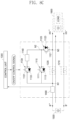
- FIGS. 8a to 8e are views illustrating an operation process in which power is supplied from a battery 1500 to a load side 1600 according to an example not in accordance with theinvention.
- an operation process in which power is supplied and cut off from the battery 1500 to the load side 1600 according to an example not in accordance with the invention will be described with reference to FIGS. 8a to 8e .
- the control unit 1300 turns on the first relay 1210. Then, the pre-charge switching element 1131 is turned on. Then, the current outputted from the battery 1500 flows to the load side 1600 through the pre-charge switching element 1131, the protective resistance 1140, and the diode 1123 of the second switching unit 1120, and pre-charges the capacitor included in the load side 1600 (see FIG. 8a ).
- the control unit 1300 turns on the second relay 1220 (ON), and most of the current flowing through the pre-charge switching element 1131 flows through the second relay 1220 (see FIG. 8b ).
- the pre-charge since an equipotential is formed between both ends of the second relay 1220, even when the second relay 1220 is turned on, sparks or arcs are not generated at the contact points of the second relay 1220.
- the control unit 1300 turns off the pre-charge switching element 1131 (see FIG. 8c ). In this case, normal current supply is made from the battery 1500 to the load side 1600.
- the control unit 1300 turns on the first switching element 1111, a portion of the current supplied from the battery 1500 to the load side 1600 through the second relay 1220 flows to the load side 1600 through the first switching element 1111 and the diode 1123 of the second switching unit 1120 (see FIG. 8d ) .
- the control unit 1300 turns off the second relay 1220 in the next step, and the current flowing from the battery 1500 to the load side 1600 now flows only through the first switching element 1111 (see FIG. 8e ).
- both ends of the second relay 1220 form an equipotential, even when the second relay 1220 is turned off, sparks or arcs are not generated at the contacts of the second relay 1220.
- FIGS. 9a to 9c are views illustrating an operation process in which charging current is supplied to the battery 1500 according to an example not in accordance with the invention.
- FIGS. 9a to 9c are views illustrating an operation process in which charging current is supplied to the battery 1500 according to an example not in accordance with theinvention.
- the control unit 1300 turns on the first relay 1210 and turns on the second switching element 1121. Then, the charging current flows toward the battery 1500 through the second switching element 1121 and the diode 1113 of the first switching unit 1110 (see current 1), and after that, when the second relay 1220 is turned on, a portion of the charging current flowing through the second switching element 1121 flows toward the battery 1500 through the second relay 1220 (see current 2), and as the control unit 1300 turns off the second switching element 1121, the charging current flows only through the second relay 1220 so that a regular charging process is performed (see FIG. 9a ).
- the control unit 1300 turns on the second switching element 1121, and then, a portion of the charging current supplied to the battery 1500 through the second relay 1220 flows to the battery 1500 through the second switching element 1121 and the diode 1113 of the first switching unit 1110 (see FIG. 9b ) .
- the control unit 1300 turns off the second relay 1220, and the current flowing to the battery 1500 now flows only through the second switching element 1121 (see FIG. 9c ).
- the control unit 1300 turns off the second relay 1220, and the current flowing to the battery 1500 now flows only through the second switching element 1121 (see FIG. 9c ).
- both ends of the second relay 1220 form an equipotential, even when the second relay 1220 is turned off, sparks or arcs are not generated at the contacts of the second relay 1220.
- FIG. 10 is a view showing the configuration of a PRA for an electric vehicle according to a modified an example not in accordance with theinvention.
- the control unit 1300 of the PRA for an electric vehicle according to the example not in accordance with the inventionshown in FIGS. 7 to 9c is not limited to a method of communicating with a main controller (not shown) or a battery management system (BMS) 1700 of the vehicle, but the control unit 1300 of the PRA for an electric vehicle according to the modified example shown in FIG. 10 adopts a CAN communication method or a LIN communication method as a method of communicating with the vehicle's main controller (not shown) or BMS.
- the power relay assembly (PRA) according to the modified example not in accordance with the invention, itfurther includes a communication unit 1700 to perform CAN communication or LIN communication with the vehicle's main controller or BMS through the communication unit 1700.
- the control unit 1300 receives an ON/hold/OFF command of the PRA from the main control unit (not shown) or the BMS of the vehicle through the communication unit 1700, and as described above with reference to FIGS. 7 to 9c , the control unit 1300 operates the PRA, and transmits status information of each stage to the main control unit (not shown) or BMS of the vehicle.
- control unit 1300 and the BMS (or the main control unit of the vehicle) are directly connected through a wire, and if a communication error occurs between the communication unit 1700 and the BMS (or the main control unit of the vehicle), the control unit 1300 and the BMS (or main control unit of the vehicle) exchange control commands and status information with each other by transmitting and receiving a PWM signal through a wire.
- control unit 1300 and the BMS (or the vehicle main control unit) through the communication unit 1700 illustrated in FIG. 10 The function performed between the control unit 1300 and the BMS (or the vehicle main control unit) through the communication unit 1700 illustrated in FIG. 10 is the same as that described with reference to FIG. 6 , so that a detailed description thereof will be omitted.
Description
- The present invention relates to a power relay assembly (PRA) and a driving method thereof, and more particularly, to a PRA for an electric vehicle and a driving method thereof.
- In general, a power relay assembly (PRA) is a power blocking device that connects and disconnects power from a battery through a Power Control Unit (PCU) to a motor in electric vehicles and hybrid vehicles, and is a core component that serves as a main gate for supplying power.
- In addition, the power relay assembly (PRA) acts as a safety device to completely cut off power in the event of a system failure or maintenance so that it plays a very important safety role in electric vehicles/hybrid vehicles.
- These PRAs consist of high-voltage relays such as precharging relays (450V, 10A or more) and main relays (450V, 100 to 150A or more) and components such as high voltage/high current bus bars and terminals for wiring connections to the battery/inverter.
- Among them, the key component is a high voltage relay that serves to connect and disconnect high voltage/high current. Conventionally, as such a high voltage relay, a mechanical relay structure in which a special gas (for example, H2 gas) is injected and sealed to prevent sparks that may occur at the contact point of the relay is adopted.
- However, since the high voltage relay is heavy due to special gas, it increases the overall weight of the PRA. As a result, there is a problem that the fuel efficiency of the vehicle is lowered.
- In addition, since the high voltage relay not only has a complicated mechanical structure, but also has a high material cost of its parts, the price of that part is high. As a result, there is a problem that the cost of the PRA is increased.
- In addition, the PRA including the high voltage relay requires an increase in wiring due to the addition of peripheral devices. As a result, there is a problem that the arrangement of the wiring becomes complicated.
- As an example of the prior art for solving these problems, as shown in
FIG. 1 , a smart PRA using a semiconductor switching element has been proposed.Korea Patent No. 10-0559398 FIG. 1 (Title of invention: vehicle power connection control device for hybrid and fuel cell) turns on the secondmain relay 7 that connects the -terminal of the battery and the inverter to each other at the initial start-up, and before the firstmain relay 5 is connected, performs pulse width modulation (PWM) control of thepower semiconductor 6 to intermittently flow current and charge thecapacitor 8b in advance, and forms an equipotential for the same voltage across the firstmain relay 5, and then connects the firstmain relay 5, so that when the firstmain relay 5 is connected, sparks are prevented from occurring at both ends of the firstmain relay 5. - In addition, when the power supply is cut off, in the state where the first
main relay 5, thepower semiconductor 6, and the secondmain relay 7 are simultaneously turned on, only the firstmain relay 5 is first turned off. At this time, since the current flowing through the firstmain relay 5 continues to flow through thepower semiconductor 6, the firstmain relay 5 can safely cut off power because sparks do not occur at the contact point. - However, in the case of such prior art, since it is possible to cut off the normal power while supplying power from the high voltage battery of the electric vehicle to the load (inverter) but the operation to cut off the power when charging the high voltage battery cannot be performed, a new structure of a PRA driving apparatus for an electric vehicle is required.
- Another example of the prior art is the patent application
EP2774798 A2 , which discloses a battery management system which claims preventing the fusion of a relay by avoiding arcing and spiking when the relay is turned off (opened). The battery management system includes one or more battery packs. A master battery management unit is responsible for sensing voltages and/or currents of the battery packs. Main relays are connected between the battery packs and loads and turned on or off by the master battery management unit. Sub relays connected to the main relays in parallel and can be turned on or off by the master battery management unit. The sub relays have resistors, in such a way that when they switch (from a state in which the battery packs and the loads are electrically connected to a state in which the battery packs and the loads are electrically disconnected), the sub relays are first turned on and the main relays are then turned off. However, this battery management system suffers from energy loss due to said resistors, even leading to spark generation. - In the state of the art it is also known the patent application
US 2010/0127663 A1 , which discloses a rechargeable battery system comprising: a battery, a fuse connected in series to the battery, and a current cut-off circuit (with a timer) that detects an excessive current flowing in the battery and controls several relays. These relays can reliably cut-off excessive battery current without fusing relay contacts together, and excessive battery current can also be cut-off by the fuse. - The invention is set out in the appended set of claims.
- The present invention is to provide a power relay assembly for an electric vehicle and a driving method thereof that can perform power supply and shutdown while preventing sparking of the relay not only when a high voltage battery of an electric vehicle is discharged to supply power to a load, but also when a charging current is supplied to a high voltage battery.
- According to a first preferred embodiment of the present invention for solving the above-described problems, a power relay assembly for an electric vehicle includes: a first relay connected between a negative terminal of a battery and a negative terminal of a load side; a second relay connected between a positive terminal of the battery and a positive terminal of the load side; a first switching unit having one end connected to one end of the second relay on the positive terminal side of the battery and the other end connected to a second switching unit; the second switching unit is connected to the first switching unit, one end is connected to the load side one end of the second relay; a voltage control module configured to output a voltage control signal to the first switching unit according to a control signal inputted from a control unit to limit an amount of current flowing through the first switching unit; and the control unit configured to control the first relay, the second relay, the first switching unit, and the second switching unit by outputting a control signal.
- In addition, each of the first switching unit and the second switching unit may include: a switching element configured to be turned on/off according to a control signal inputted from the control unit; and a diode connected in parallel with the switching element.
- Moreover, diodes included in each of the first switching unit and the second switching unit may have opposite directions in a forward direction.
- In addition, the diode of the first switching unit may be set so that the direction towards the positive terminal of the battery is forward, and the diode of the second switching unit may be set so that the direction towards the positive terminal of the load side is forward.
- Furthermore, the switching element included in the first switching unit and the second switching unit may be implemented as an Insulated Gate Bipolar Transistor (IGBT) or Field Effect Transistor (FET), wherein the diode included in the first switching unit and the second switching unit may be implemented as an internal diode included in an IGBT or FET.
- Moreover, when supplying power from the battery to the load side, the control unit may turn on the first relay, turn on the switching element of the first switching unit through the voltage control module to perform pre-charge by allowing a current outputted from the battery to flow to the load side through the switching element of the first switching unit and the diode of the second switching unit, and when equipotential between both ends of the second relay is formed, turn on the second relay and turns off the first switching unit through the voltage control module.
- In addition, when the power supply from the battery to the load side is cut off, the control unit may turn on the switching element of the first switching unit through the voltage control module to allow the current outputted from the battery to flow to the load side through the second relay, the switching element of the first switching unit, and the diode of the second switching unit, and then turn off the second relay, and then turn off the switching element of the first switching unit through the voltage control module to cut off power supply.
- Moreover, when charging current is supplied to the battery, the control unit may turn on the switching element of the second switching unit to allow the charging current to flow to the battery through the switching element of the second switching unit and the diode of the first switching unit, and then form equipotential between both ends of the second relay, and then turn on the second relay to allow the charging current to flow through the second relay, and then perform regular charging by turning off the switching element of the second switching unit.
- Furthermore, when cutting off charging current supply, the control unit may turn on a switching element of the second switching unit to allow a charging current to flow to the battery through a switching element of the second switching unit and a diode of the first switching unit, and then turn off the second relay to cut off the charging current flowing through the second relay, and then cut off the supply of charging current by turning off the switching element of the second switching unit.
- In addition, the power relay assembly may further include a current sensor installed between a positive terminal of the battery and one end of the second relay, and configured to measure at least one of a current outputted from the battery and a current flowing into the battery and output a current value to the control unit, wherein the control unit may output the control signal according to a current value inputted from the current sensor.
- In addition, the power relay assembly may further include a communication unit configured to perform communication according to a CAN communication method or a LIN communication method with a main controller of a vehicle or a Battery Management System (BMS), receive a control command instructing to start (ON) or stop (OFF) the power relay assembly from the main controller or the BMS to output the received control command to the control unit, and transmit status information of the power relay assembly inputted from the control unit to the main controller or the BMS.
- On the other hand, according to a first preferred embodiment of the present invention for solving the above-described problems, a method of driving a power relay assembly for an electric vehicle including a first relay connected between a negative terminal of a battery and a negative terminal of a load side, a second relay connected between a first node to which a positive terminal of the battery is connected and a second node to which a positive terminal of the load side is connected, a first switching unit connected between the first node and a second switching unit, and a second switching unit connected between the first switching unit and the second node, wherein the first switching unit and the second switching unit include a switching element and a diode connected in parallel with the switching element, respectively, includes: when supplying power from the battery to the load side, turning on the first relay; turning on the switching element of the first switching unit through a voltage control module to allow the current outputted from the battery to flow to the load side through the switching element of the first switching unit and the diode of the second switching unit to perform pre-charge; and when equipotential between both ends of the second relay is formed, turning on the second relay and turning off the first switching unit through the voltage control module.
- In addition, the method may further include: when power supply to the load side is cut off from the battery, turning on the switching element of the first switching unit through the voltage control module to allow the current outputted from the battery to flow to the load side through the second relay and a switching element of the first switching unit and a diode of the second switching unit; turning off the second relay; and turning off the switching element of the first switching unit through the voltage control module to cut off the power supply.
- In addition, the method may further include: when charging current is supplied to the battery, turning on the switching element of the second switching unit to allow the charging current to flow to the battery through the switching element of the second switching unit and the diode of the first switching unit to form equipotential between both ends of the second relay; turning on the second relay to allow a charging current to flow through the second relay; and performing regular charging by turning off the switching element of the second switching unit.
- Furthermore, the method may further include: when cutting off the charging current supply, turning on a switching element of the second switching unit to allow a charging current to flow to the battery through a switching element of the second switching unit and a diode of the first switching unit; turning off the second relay to cut off the charging current flowing through the second relay; and cutting off charging current supply by turning off the switching element of the second switching unit.
- In an example not in accordance with the invention, a power relay assembly for an electric vehicle includes: a first relay connected between a negative terminal of a battery and a negative terminal of a load side; a second relay connected between a positive terminal of the battery and a positive terminal of the load side; a first switching unit having one end connected to one end of the second relay on the positive terminal side of the battery and the other end connected to a second switching unit; the second switching unit is connected to the first switching unit, one end is connected to the load side one end of the second relay; a pre-charge switching unit having one end connected to one end of the second relay on the positive terminal side of the battery and the other end connected to a protective resistance; the protective resistance connected between the pre-charge switching unit and a connection node of the first switching unit and the second switching unit; and a control unit configured to output a control signal to control on/off of the first relay, the second relay, the first switching unit, the second switching unit, and the pre-charge switching unit.
- In addition, each of the first switching unit and the second switching unit may include: a switching element configured to be turned on/off according to a control signal inputted from the control unit; and a diode connected in parallel with the switching element.
- Moreover, diodes included in each of the first switching unit and the second switching unit may have opposite directions in a forward direction.
- In addition, the diode of the first switching unit may be set so that the direction towards the positive terminal of the battery is forward, and the diode of the second switching unit may be set so that the direction towards the positive terminal of the load side is forward.
- Moreover, the switching element included in the first switching unit and the second switching unit may be implemented as an Insulated Gate Bipolar Transistor (IGBT) or Field Effect Transistor (FET), wherein the diode included in the first switching unit and the second switching unit may be implemented as an internal diode included in an IGBT or FET.
- In addition, when supplying power from the battery to the load side, the control unit may turn on the first relay, turn on the pre-charge switching unit to perform pre-charge by allowing a current outputted from the battery to flow to the load side through the pre-charge switching unit and the diode of the second switching unit, and when equipotential between both ends of the second relay is formed, turn on the second relay and turns off the pre-charge switching unit.
- In addition, when the power supply from the battery to the load side is cut off, the control unit may turn on the switching element included in the first switching unit to allow the current outputted from the battery to flow to the load side through the second relay, the switching element of the first switching unit, and the diode of the second switching unit, and then turn off the second relay, and then turn off the switching element included in the first switching unit to cut off power supply.
- Moreover, when charging current is supplied to the battery, the control unit may turn on the switching element of the second switching unit to allow the charging current to flow to the battery through the switching element of the second switching unit and the diode of the first switching unit, and then form equipotential between both ends of the second relay, and then turn on the second relay to allow the charging current to flow through the second relay, and then perform regular charging by turning off the switching element of the second switching unit.
- In addition, when cutting off charging current supply, the control unit may turn on a switching element of the second switching unit to allow a charging current to flow to the battery through a switching element of the second switching unit and a diode of the first switching unit, and then turn off the second relay to cut off the charging current flowing through the second relay, and then cut off the supply of charging current by turning off the switching element of the second switching unit.
- Furthermore, the power relay assembly may further include a current sensor installed between a positive terminal of the battery and one end of the second relay, and configured to measure at least one of a current outputted from the battery and a current flowing into the battery and output a current value to the control unit, wherein the control unit may output a control signal according to the current value inputted from the current sensor.
- In addition, the power relay assembly may further include a communication unit configured to perform communication according to a CAN communication method or a LIN communication method with a main controller of a vehicle or a Battery Management System (BMS), receive a control command instructing to start (ON) or stop (OFF) the power relay assembly from the main controller or the BMS to output the received control command to the control unit, and transmit status information of the power relay assembly inputted from the control unit to the main controller or the BMS.
- In an example not in accordance with the invention, a method of driving a power relay assembly for an electric vehicle including a first relay connected between a negative terminal of a battery and a negative terminal of a load side, a second relay connected between a first node to which a positive terminal of the battery is connected and a third node to which a positive terminal of the load side is connected, a first switching unit connected between the first node and a second node, a second switching unit connected between the second node and the third node, and a pre-charge switching unit and a protective resistance connected in series between the first node and the second node, wherein each of the first switching unit and the second switching unit includes a switching element and a diode connected in parallel with the switching element, includes: when supplying power from the battery to the load side, turning on the first relay; turning on the pre-charge switching unit to allow the current outputted from the battery to flow to the load side through the pre-charge switching unit and the diode of the second switching unit to perform pre-charge; and when equipotential between both ends of the second relay is formed, turning on the second relay and turning off the pre-charge switching unit.
- In addition, the method may further include: when power supply from the battery to the load side is cut off, turning on the switching element included in the first switching unit to allow the current outputted from the battery to flow to the load side through the second relay and a switching element of the first switching unit and a diode of the second switching unit; turning off the second relay; and turning off the switching element included in the first switching unit to cut off the power supply.
- Moreover, the method may further include: when charging current is supplied to the battery, turning on the switching element of the second switching unit to allow the charging current to flow to the battery through the switching element of the second switching unit and the diode of the first switching unit to form equipotential between both ends of the second relay; turning on the second relay to allow a charging current to flow through the second relay; and performing regular charging by turning off the switching element of the second switching unit.
- Furthermore, the method may further include: when cutting off the charging current supply, turning on a switching element of the second switching unit to allow a charging current to flow to the battery through a switching element of the second switching unit and a diode of the first switching unit; turning off the second relay to cut off the charging current flowing through the second relay; and cutting off charging current supply by turning off the switching element of the second switching unit.
- A power relay assembly for an electric vehicle and a driving method thereof according to the first embodiment of the present invention connect the first switching unit and the second switching unit connected in series to each other in parallel with the relay switch, and allow the first switching unit and the second switching unit to include semiconductor switching elements and diodes therein, so that not only when power is supplied from the battery to the load side, but also when charging is performed by supplying a charging current to the battery, it is possible to supply or cut off power while preventing sparks and arcs at the relay contact point. In addition, by using the current characteristics of the semiconductor switching element included in the first switching unit or the second switching unit, the current is limited by adjusting the voltage applied to the semiconductor switching element so that no more than a constant current flows during the pre-charge operation, and thus, it is possible to prevent the rapid current from flowing without installing a separate resistor.
- A power relay assembly for an electric vehicle and a driving method thereof according to an example not in accordance with the invention connect a pre-charge switching unit and a first switching unit and a second switching unit connected in series with each other in parallel with a relay switch and allow the first switching unit and the second switching unit to include semiconductor switching elements and diodes therein, so that not only when power is supplied from the battery to the load side, but also when charging is performed by supplying a charging current to the battery, it is possible to supply or cut off power while preventing sparks and arcs at the relay contact point.
-
-
FIG. 1 is a view showing an example of a smart PRA according to the prior art. -
FIG. 2 is a view showing the configuration of a PRA for an electric vehicle according to a first preferred embodiment of the present invention. -
FIGS. 3a and 3b are graphs showing output current characteristics of typical IGBT and FET, respectively. -
FIGS. 4a to 4e are views illustrating an operation process in which power is supplied from a battery to a load side according to a preferred embodiment of the present invention. -
FIGS. 5a to 5c are views illustrating an operation process in which charging current is supplied to a battery according to a first preferred embodiment of the present invention. -
FIG. 6 is a view showing the configuration of a PRA for an electric vehicle according to a modified embodiment of the first preferred embodiment of the present invention. -
FIG. 7 is a view showing the configuration of a PRA for an electric vehicle according to an example not in accordance with the invention. -
FIGS. 8a to 8e are views illustrating an operation process in which power is supplied from a battery to a load side according to an example not in accordance with theinvention. -
FIGS. 9a to 9c are views illustrating an operation process in which charging current is supplied to a battery according to an example not in accordance with theinvention. -
FIG. 10 is a view showing the configuration of a PRA for an electric vehicle according to an example not in accordance with theinvention. - Hereinafter, preferred embodiments of the present invention will be described with reference to the accompanying drawings.
-
FIG. 2 is a view showing a configuration of a power relay assembly (PRA) for an electric vehicle according to a first preferred embodiment of the present invention. - Referring to
FIG. 2 , a PRA for an electric vehicle according to the first preferred embodiment of the present invention (hereinafter abbreviated as "driving device") includes afirst relay 210, asecond relay 220, afirst switching unit 110, asecond switching unit 120, avoltage control module 130, acurrent sensor 400, and acontrol unit 300. Hereinafter, the operation of each component will be described. - The
first relay 210 is connected between the - terminal of thebattery 500 and the - terminal of theload side 600, and when power is supplied to theload side 600 and thebattery 500 is charged according to the control signal of thecontrol unit 300, thefirst relay 210 is first turned on to electrically connect the-terminal of thebattery 500 and the load side 600-terminal, and when power supply is stopped and charging is stopped, thefirst relay 210 is turned off at the end, thereby electrically disconnecting the - terminal of thebattery 500 and the - terminal of theload side 600. - The
second relay 220 is connected between the + terminal of thebattery 500 and the + terminal of theload side 600, and is turned on according to the control signal of thecontrol unit 300, so that regular power is supplied to theload side 600, and thesecond relay 220 allows the charging current to be supplied from the charging device (not shown) connected to theload side 600 to the side of thebattery 500. - The
first switching unit 110 and thesecond switching unit 120 are connected in series with each other, and thefirst switching unit 110 and thesecond switching unit 120 connected in series with each other are connected in parallel to both ends of thesecond relay 220. - One end of the
first switching unit 110 is connected to one end of thesecond relay 220 on the positive terminal side of thebattery 500, and the other end of thefirst switching unit 110 is connected to one end of thesecond switching unit 120 to control the flow of current according to the voltage control signal inputted from thevoltage control module 130. - The
first switching unit 110 may include a switching element (hereinafter referred to as a "first switching element") 111 that is turned on/off according to a voltage control signal input from thevoltage control module 130, and adiode 113 connected in parallel thereto. - The
first switching element 111 is a semiconductor switching element, for example, an Insulated Gate Bipolar Transistor (IGBT) or a Field Effect Transistor (MOS-FET). Thediode 113 connected in parallel with thesemiconductor switching element 111 is connected in parallel with thesemiconductor switching element 111 such that when thesemiconductor switching element 111 is turned on, the direction opposite to the current flowing in thesemiconductor switching element 111 becomes the forward direction of thediode 113, and thediode 113 may be a separate diode combined with asemiconductor switching element 111, or may be implemented with a diode inside thesemiconductor switching element 111 like a parasitic diode. - Moreover, one end of the
second switching unit 120 is connected to the other end of thefirst switching unit 110, and the other end is connected to one end of theload side 600 of thesecond relay 220 to control the flow of current according to the control signal of thecontrol unit 300. - The
second switching unit 120 may include a switching element (hereinafter referred to as a "second switching element") 121 which is turned on/off according to the control signal of thecontrol unit 300, and adiode 123 connected in parallel thereto. Thesecond switching element 121 is a semiconductor switching element, and thediode 123 connected in parallel with the semiconductor switching element is connected in parallel with thesemiconductor switching element 121 such that the direction opposite to the current flowing when thesemiconductor switching element 121 is turned on is to be forward. - In the first preferred embodiment of the present invention, the switching
element 121 may be implemented as an IGBT or FET, and thediode 123 connected in parallel to theswitching element 121 may be implemented as a separate diode or may be implemented as an internal diode of the semiconductor switching element like a parasitic diode. - Here, in the case where the
diodes first switching unit 110 and thesecond switching unit 120 are implemented with internal diodes, when switchingelements elements - At this time, the
diode 113 of thefirst switching unit 110 and thediode 123 of thesecond switching unit 120 are set to have opposite forward directions, and thediode 113 of thefirst switching unit 110 is installed such that the positive terminal side of thebattery 500 from thesecond switching unit 120 is in the forward direction, and thediode 123 of thesecond switching unit 120 is installed such that the positive terminal side of theload side 600 from thefirst switching unit 110 is in the forward direction. - Furthermore, according to the control signal input from the
control unit 300, thevoltage control module 130 forms an equipotential across thesecond relay 220 by turning thefirst switching element 111 on/off, and limits the amount of current flowing through thefirst switching element 111. - Specifically, upon receiving the
first switching element 111 turn-on control signal for pre-charge from thecontrol unit 300, thevoltage control module 130 outputs a voltage control signal to thefirst switching element 111 so that current flows within a range in which a current greater than a predetermined value does not flow according to the characteristics of thefirst switching element 111. - If the
first switching element 111 suddenly turns on, a large current can be outputted at once from thehigh voltage battery 500 to the load side, and this large current may cause damage to thefirst switching element 111 as well as thesecond switching element 121 and the load side. Therefore, it is necessary to slowly charge the capacitor on the load side by limiting the amount of current. To this end, when thefirst switching element 111 is implemented as an IGBT, the gate-emitter voltage VGE is adjusted to operate the IGBT in the active region, and when thefirst switching element 111 is implemented as a FET, the gate-source voltage VGS is adjusted to operate the FET in the saturation region. -
FIGS. 3a and 3b are graphs showing output current characteristics of typical IGBT and FET, respectively. This will be described with reference toFIGS. 3a and 3b . - First, as shown in
FIG. 3a , in the case of an IGBT, when the gate-emitter voltage VGE exceeds the threshold voltage VTH, current flows, and at this time, as VCE increases while the collector-emitter voltage VCE is less than VGE-VTH, the current increases linearly but if the collector-emitter voltage VCE is greater than VGE-VTH, the current value remains constant even as VCE increases. The first preferred embodiment of the present invention defines this region as the active region, and when thefirst switching element 111 is an IGBT, thevoltage control module 130 outputs the gate voltage and the emitter voltage so that thefirst switching element 111 operates in the active region. Particularly, the first preferred embodiment of the present invention controls the current flowing through thefirst switching element 111 to be maintained at 20A or less, and if the graph ofFIG. 3a is applied to the present invention, as indicated by the red dotted line, thevoltage control module 130 outputs the gate voltage and the emitter voltage so that the VGE-VTH voltage value becomes 2V to 4V, and the collector-emitter voltage value becomes about 4V to 10V. - Similarly, as shown in
FIG. 3b , in the case of a MOS-FET, when the gate-source voltage VGS exceeds the threshold voltage VTH, current flows and at this time, as the VDS increases while the drain-to-source voltage (VDS) is less than VGS-VTH, the current increases linearly, and when the drain-source voltage VDS is greater than VGS-VTH, the current value remains constant even when VDS increases. The first preferred embodiment of the present invention defines this region as a saturation region, and when thefirst switching element 111 is a MOS-FET, thevoltage control module 130 outputs the gate voltage and the source voltage so that thefirst switching element 111 operates in the saturation region. Particularly, the first preferred embodiment of the present invention controls the current flowing through thefirst switching element 111 to be maintained at 20A or less, and if the graph ofFIG. 3b is applied to the present invention, as indicated by the red dotted line, thevoltage control module 130 outputs the gate voltage and the source voltage so that the VGS-VTH voltage value becomes 2V to 4V and the drain-source voltage value is about 5V to 10V. - The
current sensor 400 is installed on the positive terminal side of thebattery 500 such that the current outputted from thebattery 500 or the charging current inputted to thebattery 500 is measured and the measured current value is outputted to thecontrol unit 300. - The
control unit 300 receives and examines the current value from thecurrent sensor 400, and accordingly, outputs control signals for controlling on/off of thefirst relay 210, thesecond relay 220, thefirst switching element 111, and thesecond switching element 121 to each component. However, the control signal for controlling thefirst switching element 111 is outputted to the voltage control module as described above. - Meanwhile, in the PRA for an electric vehicle according to the first preferred embodiment of the present invention shown in
FIG. 2 , a connection point between each component is defined as a node and the first preferred embodiment of the present invention can also be briefly expressed as follows. - The
first relay 210 is connected between the negative terminal of thebattery 500 and the negative terminal of theload side 600, and thesecond relay 220 is connected between the first node N1 to which the positive terminal of thebattery 500 is connected and the second node N2 to which the positive terminal of theload side 600 is connected. Thefirst switching unit 110 is connected between the first node N1 and thesecond switching unit 120, and thesecond switching unit 120 is connected between thefirst switching unit 110 and the second node N2. - When the
first switching element 111 is implemented as an IGBT (N-type FET), a collector (drain) is connected to the first node N1, and an emitter (source) is connected to thesecond switching element 121. Similarly, when thesecond switching element 121 is implemented as an IGBT (N-type FET), the collector (drain) is connected to the second node N2, and the emitter (source) is connected to thefirst switching element 111. - Hereinafter, with reference to
FIGS. 4a to 5c , a function of each component of the power relay assembly for an electric vehicle and a method of driving the power relay assembly for an electric vehicle according to the first preferred embodiment of the present invention will be described. -
FIGS. 4a to 4e are views illustrating an operation process in which power is supplied from abattery 500 to aload side 600 according to a first preferred embodiment of the present invention. Hereinafter, an operation process in which power is supplied and cut off from thebattery 500 to theload side 600 according to a preferred embodiment of the present invention will be described with reference toFIGS. 4a to 4e . - First, in a state where all of the switching elements are open, when power is supplied from the
battery 500 to theload side 600, thecontrol unit 300 turns on thefirst relay 210. Then, thecontrol unit 300 outputs a control signal to turn on thefirst switching element 111 to thevoltage control module 130, and thevoltage control module 130 outputs voltages to the gate and emitter (or source) of thefirst switching element 111, respectively, to turn on the first switching element. At this time, as described with reference toFIGS. 3a and 3b , the voltage outputted from thevoltage control module 130 to thefirst switching element 111 is appropriately selected according to thefirst switching element 111 so that a current of less than 20A flows through thefirst switching element 111. - Then, the current outputted from the
battery 500 flows to theload side 600 through thefirst switching element 111 and thediode 123 of thesecond switching unit 120, and the capacitor included in theload side 600 is pre-charged (seeFIG. 4a ). - After the pre-charge is completed, the
control unit 300 turns on thesecond relay 220, and a current greater than the current flowing through thefirst switching element 111 flows through the second relay 220 (SeeFIG. 4b ). When pre-charge is completed, since an equipotential is formed between both ends of thesecond relay 220, even when thesecond relay 220 is turned on, sparks or arcs are not generated at the contact points of thesecond relay 220. - When the current flows through the
second relay 220, thecontrol unit 300 outputs a control signal to thevoltage control module 130 to turn off thefirst switching element 111, and thevoltage control module 130 turns off the first switching element 111 (seeFIG. 4c ). In this case, normal current supply is made from thebattery 500 to theload side 600. - Thereafter, when the power supply is cut off from the
battery 500 to theload side 600, thecontrol unit 300 outputs a control signal to thevoltage control module 130, and thevoltage control module 130 outputs a control signal to the gate and emitter (or source) of thefirst switching element 111 as inFIG. 4a to turn on thefirst switching element 111, and part of the current supplied from thebattery 500 to theload side 600 through thesecond relay 220 flows through thefirst switching element 111 and thediode 123 of thesecond switching unit 120 to the load side 600 (seeFIG. 4d ). - The
control unit 300 turns off thesecond relay 220 in the next step, and the current flowing from thebattery 500 to theload side 600 now flows only through the first switching element 111 (seeFIG. 4e ). In a state where the current flows through thesecond relay 220 and thefirst switching element 111 together, since both ends of thesecond relay 220 form an equipotential, even when thesecond relay 220 is turned off, sparks or arcs are not generated at the contacts of thesecond relay 220. -
FIGS. 5a to 5c are views illustrating an operation process in which charging current is supplied to thebattery 500 according to a preferred embodiment of the present invention. - First, in a state where all of the switching elements are open, when starting to supply the charging current to the side of the
battery 500, thecontrol unit 300 turns on thefirst relay 210 and turns on thesecond switching element 121. Then, the charging current flows toward thebattery 500 through thesecond switching element 121 and thediode 113 of the first switching unit 110 (see current ①), and after that, when thesecond relay 220 is turned on, a portion of the charging current flowing through thesecond switching element 121 flows toward thebattery 500 through the second relay 220 (see current ②), and as thecontrol unit 300 turns off thesecond switching element 121, the charging current flows only through thesecond relay 220 so that a regular charging process is performed (seeFIG. 5a ). - In the process of completing the charging by cutting off the charging current, the
control unit 300 turns on thesecond switching element 121, and then, a portion of the charging current supplied to thebattery 500 through thesecond relay 220 flows to thebattery 500 through thesecond switching element 121 and thediode 113 of the first switching unit 110 (seeFIG. 5b ). - Thereafter, the
control unit 300 turns off thesecond relay 220, and the current flowing to thebattery 500 now flows only through the second switching element 121 (seeFIG. 5c ). In a state where the current flows through thesecond relay 220 and thesecond switching element 121 together, since both ends of thesecond relay 220 form an equipotential, even when thesecond relay 220 is turned off, sparks or arcs are not generated at the contacts of thesecond relay 220. - Finally, when the
control unit 300 turns off thesecond switching element 121, the charging current flowing to thebattery 500 is completely cut off, and the charging process of thebattery 500 ends. -
FIG. 6 is a view showing the configuration of a PRA for an electric vehicle according to a modified embodiment of the first preferred embodiment of the present invention. - The
control unit 300 of the PRA for an electric vehicle according to the first embodiment shown inFIGS. 2 to 5c is not limited to a method of communicating with a main controller (not shown) or a battery management system (BMS) 700 of the vehicle, but thecontrol unit 300 of the PRA for an electric vehicle according to the modified embodiment shown inFIG. 6 adopts a method of performing communication with a main controller (not shown) or a Battery Management System (BMS) of a vehicle. For this, the power relay assembly (PRA) further includes acommunication unit 700 to perform CAN communication or LIN communication with the vehicle's main controller or BMS through thecommunication unit 700. - Referring to
FIG. 6 , thecommunication unit 700 of the modified embodiment of the present invention performs communication with the BMS in a CAN communication method, and thecontrol unit 300 of the PRA receives a control command indicating an operation start (PRA ON), maintenance, and operation stop (PRA OFF) of the PRA from the BMS through thecommunication unit 700, and operates the PRA as described with reference toFIGS. 2 to 5c according to the received control command. - In addition, in the process of performing the on/hold/ off operation of the PRA, whenever the detailed operations described with reference to
FIG. 2 to 5c is performed, thecontrol unit 300 transmits status information indicating each state to the BMS through thecommunication unit 700, or after the on/hold/off operation of the PRA is completed, transmits status information indicating this to the BMS as status information through thecommunication unit 700. The BMS receives status information, checks whether the PRA is abnormal, and controls the PRA based on this. - In addition, the
control unit 300 is connected directly to the vehicle's main controller (not shown) or BMS with a wire, so that when a communication error occurs between the vehicle's main controller or the BMS and thecommunication unit 700, thecontrol unit 300 provides a fail-safety function by mutually transmitting and receiving control commands and status information using a PWM signal. - At this time, the control command transmitted from the vehicle's main controller or BMS to the
control unit 300 can be identified by adjusting the duty ratio of the PWM signal. For example, the PRA ON command can be transmitted as a PWM signal having a duty ratio of 80% to thecontrol unit 300, and the PRA OFF command can be transmitted as a PWM signal having a duty ratio of 30% to thecontrol unit 300, and thecontrol unit 300 may identify the PRA on/off/hold command, etc. by checking the duty ratio of the received PWM signal. Similarly, thecontrol unit 300 may transmit different status information as a PWM signal by adjusting the duty ratio of the PWM signal. - So far, a power relay assembly for an electric vehicle and a driving method thereof according to a first embodiment of the present invention have been described. Hereinafter, a power relay assembly for an electric vehicle and a driving method thereof according to an example not in accordance with theinvention will be described with reference to
FIGS. 7 to 10 . -
FIG. 7 is a view showing the configuration of a PRA for an electric vehicle according to an example not in accordance with the invention. - Referring to
FIG. 7 , a PRA for an electric vehicle according to an example not in accordance with the invention (hereinafter abbreviated as "driving device") includes afirst relay 1210, asecond relay 1220, afirst switching unit 1110, asecond switching unit 1120, apre-charge switching unit 1130, acurrent sensor 1400, aprotective resistance 1140, and acontrol unit 1300. Hereinafter, the operation of each component will be described. - The
first relay 1210 is connected between the - terminal of thebattery 1500 and the - terminal of theload side 1600, and when power is supplied to theload side 1600 and thebattery 1500 is charged according to the control signal of thecontrol unit 1300, thefirst relay 1210 is first turned on to electrically connect the-terminal of thebattery 1500 and the - terminal of theload side 1600, and when power supply is stopped and charging is stopped, thefirst relay 1210 is turned off at the end, thereby electrically disconnecting the - terminal of thebattery 1500 and the - terminal of theload side 1600. - The
second relay 1220 is connected between the + terminal of thebattery 1500 and the + terminal of theload side 1600, and is turned on according to the control signal of thecontrol unit 1300, so that regular power is supplied to theload side 1600, and thesecond relay 1220 allows the charging current to be supplied from the charging device (not shown) connected to theload side 1600 to the side of thebattery 1500. - The
first switching unit 1110 and thesecond switching unit 1120 are connected in series with each other, and thefirst switching unit 1110 and thesecond switching unit 1120 connected in series with each other are connected in parallel to both ends of thesecond relay 1220. - One end of the
first switching unit 1110 is connected to one end of thesecond relay 1220 on the positive terminal side of thebattery 1500, and the other end of thefirst switching unit 1110 is connected to one end of thesecond switching unit 1120 to control the flow of current according to the control signal from thecontrol unit 1300. - One end of the
second switching unit 1120 is connected to the other end of thefirst switching unit 1110, and the other end is connected to one end of theload side 1600 of thesecond relay 1220 to control the flow of current according to the control signal from thecontrol unit 1300. - The
first switching unit 1110 and thesecond switching unit 1120 are implemented with switchingelements control unit 1300, respectively, anddiodes switching elements diodes semiconductor switching elements semiconductor switching elements - Specifically, in an example not in accordance with the invention, the
switching elements diodes switching elements - In the case where the
diodes first switching unit 1110 and thesecond switching unit 1120 are implemented with internal diodes, when switchingelements elements - At this time, the
diode 1113 of thefirst switching unit 1110 and thediode 1123 of thesecond switching unit 1120 are set to have opposite forward directions, and thediode 1113 of thefirst switching unit 1110 is installed such that the positive terminal side of thebattery 1500 from thesecond switching unit 1120 is in the forward direction, and thediode 1123 of thesecond switching unit 1120 is installed such that the positive terminal side of theload side 1600 from thefirst switching unit 1110 is in the forward direction. - The
pre-charge switching unit 1130 has one end connected to one end of thesecond relay 1220 in the positive terminal side of thebattery 1500 and the other end connected to theprotective resistance 1140. That is, one end of thepre-charge switching unit 1130 is connected to the first node N1, and thesecond relay 1220, thefirst switching unit 1110, and thepre-charge switching unit 1130 are connected to the first node N1. Furthermore, like thefirst switching unit 1110 and thesecond switching unit 1120, thepre-charge switching unit 1130 includes a semiconductor switching element (hereinafter, referred to as "pre-charge switching element" 1131) that is turned on/off according to the control signal of thecontrol unit 1300 and adiode 1133 connected in parallel with this, and thepre-charge switching element 1131 is implemented with an IGBT or FET. Thediode 1133 may also be implemented with a separate diode or may be implemented with a diode inside thepre-charge switching element 1131. In addition, the forward direction of thediode 1133 of thepre-charge switching unit 1130 is set opposite to the forward direction of thediode 1123 of thesecond switching unit 1120. - The
protective resistance 1140 is connected between thepre-charge switching unit 1130 and the connection node N2 of thefirst switching unit 1110 and thesecond switching unit 1120 so that the rapid current is prevented from flowing through thepre-charge switching unit 1130. - The
current sensor 1400 is installed on the positive terminal side of thebattery 1500 such that the current outputted from thebattery 1500 or the charging current inputted to thebattery 1500 is measured and the current value is outputted to thecontrol unit 1300. - The
control unit 1300 receives and examines the current value from thecurrent sensor 1400, and accordingly, outputs to respective components the control signals for controlling on/off of thefirst relay 1210, thesecond relay 1220, the switching element (hereinafter referred to as "first switching element") 1111 of thefirst switching unit 1110, the switching element (hereinafter referred to as "second switching element") 1121 of thesecond switching unit 1120, and thepre-charge switching element 1131. - Meanwhile, in the PRA for an electric vehicle according to an example not in accordance with theinvention shown in
FIG. 7 , a connection point between each component is defined as a node and the example not in accordance with the invention can also be briefly expressed as follows. - The
first relay 1210 is connected between the negative terminal of thebattery 1500 and the negative terminal of theload side 1600, and thesecond relay 1220 is connected between the first node N1 to which the positive terminal of thebattery 1500 is connected and the third node N3 to which the positive terminal of theload side 1600 is connected. - The
first switching unit 1110 is connected between the first node N1 and the second node N2, and thesecond switching unit 1120 is connected between the second node N2 and the third node N3. Thepre-charge switching unit 1130 and theprotective resistance 1140 are connected in series with each other between the first node N1 and the second node N2. - In addition, when the
pre-charge switching element 1131 and thefirst switching element 1111 are implemented with an IGBT (N-type FET), the collector (drain) of theswitching elements second switching element 1121 is implemented with an IGBT (N-type FET), the collector (drain) is connected to the third node N3, and the emitter (source) is connected to the second node N2. - Hereinafter, with reference to
FIGS. 8a to 9c , a function of each component of the power relay assembly for an electric vehicle and a method of driving the power relay assembly for an electric vehicle according to an example not in accordance with the invention will be described. -
FIGS. 8a to 8e are views illustrating an operation process in which power is supplied from abattery 1500 to aload side 1600 according to an example not in accordance with theinvention. Hereinafter, an operation process in which power is supplied and cut off from thebattery 1500 to theload side 1600 according to an example not in accordance with the invention will be described with reference toFIGS. 8a to 8e . - First, in a state where all of the switching elements are open, when power is supplied from the
battery 1500 to theload side 1600, thecontrol unit 1300 turns on thefirst relay 1210. Then, thepre-charge switching element 1131 is turned on. Then, the current outputted from thebattery 1500 flows to theload side 1600 through thepre-charge switching element 1131, theprotective resistance 1140, and thediode 1123 of thesecond switching unit 1120, and pre-charges the capacitor included in the load side 1600 (seeFIG. 8a ). - After pre-charge is completed, the
control unit 1300 turns on the second relay 1220 (ON), and most of the current flowing through thepre-charge switching element 1131 flows through the second relay 1220 (seeFIG. 8b ). When the pre-charge is completed, since an equipotential is formed between both ends of thesecond relay 1220, even when thesecond relay 1220 is turned on, sparks or arcs are not generated at the contact points of thesecond relay 1220. - When the current flows through the
second relay 1220, thecontrol unit 1300 turns off the pre-charge switching element 1131 (seeFIG. 8c ). In this case, normal current supply is made from thebattery 1500 to theload side 1600. - Then, when the power supply is cut off from the
battery 1500 to theload side 1600, thecontrol unit 1300 turns on thefirst switching element 1111, a portion of the current supplied from thebattery 1500 to theload side 1600 through thesecond relay 1220 flows to theload side 1600 through thefirst switching element 1111 and thediode 1123 of the second switching unit 1120 (seeFIG. 8d ) . - The
control unit 1300 turns off thesecond relay 1220 in the next step, and the current flowing from thebattery 1500 to theload side 1600 now flows only through the first switching element 1111 (seeFIG. 8e ). In a state where the current flows through thesecond relay 1220 and thefirst switching element 1111 together, since both ends of thesecond relay 1220 form an equipotential, even when thesecond relay 1220 is turned off, sparks or arcs are not generated at the contacts of thesecond relay 1220. -
FIGS. 9a to 9c are views illustrating an operation process in which charging current is supplied to thebattery 1500 according to an example not in accordance with the invention.FIGS. 9a to 9c are views illustrating an operation process in which charging current is supplied to thebattery 1500 according to an example not in accordance with theinvention. - First, in a state where all of the switching elements are open, when starting to supply the charging current to the side of the
battery 1500, thecontrol unit 1300 turns on thefirst relay 1210 and turns on thesecond switching element 1121. Then, the charging current flows toward thebattery 1500 through thesecond switching element 1121 and thediode 1113 of the first switching unit 1110 (see current ①), and after that, when thesecond relay 1220 is turned on, a portion of the charging current flowing through thesecond switching element 1121 flows toward thebattery 1500 through the second relay 1220 (see current ②), and as thecontrol unit 1300 turns off thesecond switching element 1121, the charging current flows only through thesecond relay 1220 so that a regular charging process is performed (seeFIG. 9a ). - In the process of completing the charging by cutting off the charging current, the
control unit 1300 turns on thesecond switching element 1121, and then, a portion of the charging current supplied to thebattery 1500 through thesecond relay 1220 flows to thebattery 1500 through thesecond switching element 1121 and thediode 1113 of the first switching unit 1110 (seeFIG. 9b ) . - Thereafter, the
control unit 1300 turns off thesecond relay 1220, and the current flowing to thebattery 1500 now flows only through the second switching element 1121 (seeFIG. 9c ). In a state where the current flows through thesecond relay 1220 and thesecond switching element 1121 together, since both ends of thesecond relay 1220 form an equipotential, even when thesecond relay 1220 is turned off, sparks or arcs are not generated at the contacts of thesecond relay 1220. - Finally, when the
control unit 1300 turns off thesecond switching element 1121, the charging current flowing to thebattery 1500 is completely cut off, and the charging process of thebattery 1500 ends. -
FIG. 10 is a view showing the configuration of a PRA for an electric vehicle according to a modified an example not in accordance with theinvention. - The
control unit 1300 of the PRA for an electric vehicle according to the example not in accordance with the inventionshown inFIGS. 7 to 9c is not limited to a method of communicating with a main controller (not shown) or a battery management system (BMS) 1700 of the vehicle, but thecontrol unit 1300 of the PRA for an electric vehicle according to the modified example shown inFIG. 10 adopts a CAN communication method or a LIN communication method as a method of communicating with the vehicle's main controller (not shown) or BMS. For this, the power relay assembly (PRA) according to the modified example not in accordance with the invention, itfurther includes acommunication unit 1700 to perform CAN communication or LIN communication with the vehicle's main controller or BMS through thecommunication unit 1700. - The
control unit 1300 receives an ON/hold/OFF command of the PRA from the main control unit (not shown) or the BMS of the vehicle through thecommunication unit 1700, and as described above with reference toFIGS. 7 to 9c , thecontrol unit 1300 operates the PRA, and transmits status information of each stage to the main control unit (not shown) or BMS of the vehicle. - In addition, the
control unit 1300 and the BMS (or the main control unit of the vehicle) are directly connected through a wire, and if a communication error occurs between thecommunication unit 1700 and the BMS (or the main control unit of the vehicle), thecontrol unit 1300 and the BMS (or main control unit of the vehicle) exchange control commands and status information with each other by transmitting and receiving a PWM signal through a wire. - The function performed between the
control unit 1300 and the BMS (or the vehicle main control unit) through thecommunication unit 1700 illustrated inFIG. 10 is the same as that described with reference toFIG. 6 , so that a detailed description thereof will be omitted. - So far, the present invention has been focused on the preferred embodiments. Those skilled in the art to which the present invention pertains will appreciate that the present invention may be implemented in a modified form without departing from the essential characteristics of the present invention. Therefore, the disclosed embodiments should be considered in descriptive sense only not in limited perspective sense. The scope of the invention is defined not by the detailed description of the invention but by the appended claims, and all differences within the scope will be construed as being included in the present invention.
Claims (7)
- A power relay assembly for an electric vehicle comprising:a first relay (210, 1210) connected between a negative terminal of a battery (500, 1500) and a negative terminal of a load side (600, 1600);a second relay (220, 1220) connected between a positive terminal of the battery (500, 1500) and a positive terminal of the load side (600, 1600); anda first switching unit (110, 1110) having one end connected to one end of the second relay (220, 1220) on the positive terminal side of the battery (500, 1500) and the other end connected to a second switching unit (120, 1120);characterized in that the power relay assembly further comprises:the second switching unit (120, 1120) having one end connected to the first switching unit (110, 1110) and the other end connected to the load side (600, 1600) one end of the second relay (220, 1220);a voltage control module (130) configured to output a voltage control signal to the first switching unit (110, 1110) according to a control signal inputted from a control unit (300, 1300) to limit an amount of current flowing through the first switching unit (110, 1110) to a value lower than a predetermined value; andthe control unit (300, 1300) configured to control the first relay (210, 1210), the second relay (220, 1220), the first switching unit (110, 1110), and the second switching unit (120, 1120) by outputting a control signal; andwherein each of the first switching unit (110, 1110) and the second switching unit (120, 1120) comprises:a semiconductor switching element (111, 121, 1111, 1121) configured to be turned on/off; anda diode (113, 123, 1113, 1123) connected in parallel with the semiconductor switching element (111, 121, 1111, 1121), andwherein the diode (113, 1113) of the first switching unit (110, 1110) is set so that the direction towards the positive terminal of the battery (500, 1500) is forward, and the diode (123,1123) of the second switching unit (120, 1120) is set so that the direction towards the positive terminal of the load side (600, 1600) is forward.
- The power relay assembly of claim 1, wherein the semiconductor switching element (111, 121, 1111, 1121) included in the first switching unit (110, 1110) and the second switching unit (120, 1120) is implemented as an Insulated Gate Bipolar Transistor, IGBT, or Field Effect Transistor, FET;
wherein the diode (113, 123, 1113, 1123) included in the first switching unit (110, 1110) and the second switching unit (120, 1120) is implemented as an internal diode (113, 123, 1113, 1123) included in an IGBT or FET. - The power relay assembly of any one of claims 1 and 2, further comprising a current sensor installed between a positive terminal of the battery (500, 1500) and one end of the second relay (220, 1220), and configured to measure at least one of a current outputted from the battery (500, 1500) and a current flowing into the battery (500, 1500) and output a current value to the control unit (300, 1300),
wherein the control unit (300, 1300) outputs a control signal according to the current value inputted from the current sensor. - The power relay assembly of any one of claims 1 and 2, further comprising a communication unit (700, 1700) configured to perform communication according to a CAN communication method or a LIN communication method with a main controller of a vehicle or a Battery Management System, BMS, receive a control command instructing to start, ON, or stop, OFF, the power relay assembly from the main controller or the BMS to output the received control command to the control unit (300, 1300), and transmit status information of the power relay assembly inputted from the control unit (300, 1300) to the main controller or the BMS.
- A method of driving a power relay assembly for an electric vehicle including a first relay (210, 1210) connected between a negative terminal of a battery (500, 1500) and a negative terminal of a load side (600, 1600), a second relay (220, 1220) connected between a first node to which a positive terminal of the battery (500, 1500) is connected and a second node to which a positive terminal of the load side (600, 1600) is connected, a first switching unit (110, 1110) connected between the first node and a second switching unit (120, 1120), and a second switching unit (120, 1120) connected between the first switching unit (110, 1110) and the second node,
wherein each of the first switching unit (110, 1110) and the second switching unit (120, 1120) comprises:a semiconductor switching element (111, 121, 1111, 1121) configured to be turned on/off; anda diode (113, 123, 1113, 1123) connected in parallel with the semiconductor switching element (111, 121, 1111, 1121), and wherein the diode (113, 1113) of the first switching unit (110, 1110) is set so that the direction towards the positive terminal of the battery (500, 1500) is forward, and the diode (123,1123) of the second switching unit (120, 1120) is set so that the direction towards the positive terminal of the load side (600, 1600) is forward,the method comprising:(a) when supplying power from the battery (500, 1500) to the load side (600, 1600), turning on the first relay (210, 1210);(b) turning on the semiconductor switching element (111, 1111) of the first switching unit (110, 1110) through a voltage control module (130) to allow the current outputted from the battery (500, 1500) to flow to the load side (600, 1600) through the semiconductor switching element (111, 1111) of the first switching unit (110, 1110) and the diode (123, 1123) of the second switching unit (120, 1120) to perform pre-charge,
Wherein the current outputted from the battery (500,1500) to flow to the load side (600,1600) is limited to a value lower than a predetermined value; and(c) when equipotential between both ends of the second relay (220, 1220) is formed, turning on the second relay (220, 1220) and turning off the first switching unit (110, 1110) through the voltage control module (130); andthe method further comprising:when charging current is supplied to the battery (500, 1500), turning on the semiconductor switching element (121,1121) of the second switching unit (120, 1120) to allow the charging current to flow to the battery (500, 1500) through the semiconductor switching element (121,1121) of the second switching unit (120, 1120) and the diode (113, 1113) of the first switching unit (110, 1110) to form equipotential between both ends of the second relay (220, 1220);turning on the second relay (220, 1220) to allow a charging current to flow through the second relay (220, 1220); andperforming regular charging by turning off the semiconductor switching element (121,1121) of the second switching unit (120, 1120) . - The method of claim 5, further comprising:when power supply to the load side (600, 1600) is cut off from the battery (500, 1500),turning on the semiconductor switching element (111, 1111) of the first switching unit (110, 1110) through the voltage control module (130) to allow the current outputted from the battery (500, 1500) to flow to the load side (600, 1600) through the second relay (220, 1220) and a semiconductor switching element (111, 1111) of the first switching unit (110, 1110) and a diode (123, 1123) of the second switching unit (120, 1120);turning off the second relay (220, 1220); andturning off the semiconductor switching element (111, 1111) of the first switching unit (110, 1110) through the voltage control module (130) to cut off the power supply.
- The method of claim 5, further comprising:when cutting off the charging current supply,turning on a semiconductor switching element (121, 1121) of the second switching unit (120, 1120) to allow a charging current to flow to the battery (500, 1500) through a semiconductor switching element (121, 1121) of the second switching unit (120, 1120) and a diode (113, 1113) of the first switching unit (110, 1110) ;turning off the second relay (220, 1220) to cut off the charging current flowing through the second relay (220, 1220); andcutting off charging current supply by turning off the semiconductor switching element (121, 1121) of the second switching unit (120, 1120).
Priority Applications (1)
| Application Number | Priority Date | Filing Date | Title |
|---|---|---|---|
| EP20187227.2A EP3744557A1 (en) | 2017-12-28 | 2018-12-18 | Power relay assembly for an electric vehicle and driving method thereof |
Applications Claiming Priority (3)
| Application Number | Priority Date | Filing Date | Title |
|---|---|---|---|
| KR1020170183020A KR102087702B1 (en) | 2017-12-28 | 2017-12-28 | Power relay assembly driving apparatus and method for electric vehicle |
| KR1020170183019A KR102087701B1 (en) | 2017-12-28 | 2017-12-28 | Power relay assembly driving apparatus and method for electric vehicle |
| PCT/KR2018/016131 WO2019132373A1 (en) | 2017-12-28 | 2018-12-18 | Electric vehicle power relay assembly and driving method therefor |
Related Child Applications (2)
| Application Number | Title | Priority Date | Filing Date |
|---|---|---|---|
| EP20187227.2A Division-Into EP3744557A1 (en) | 2017-12-28 | 2018-12-18 | Power relay assembly for an electric vehicle and driving method thereof |
| EP20187227.2A Division EP3744557A1 (en) | 2017-12-28 | 2018-12-18 | Power relay assembly for an electric vehicle and driving method thereof |
Publications (3)
| Publication Number | Publication Date |
|---|---|
| EP3722142A1 EP3722142A1 (en) | 2020-10-14 |
| EP3722142A4 EP3722142A4 (en) | 2021-08-04 |
| EP3722142B1 true EP3722142B1 (en) | 2023-08-16 |
Family
ID=67067725
Family Applications (2)
| Application Number | Title | Priority Date | Filing Date |
|---|---|---|---|
| EP20187227.2A Pending EP3744557A1 (en) | 2017-12-28 | 2018-12-18 | Power relay assembly for an electric vehicle and driving method thereof |
| EP18897183.2A Active EP3722142B1 (en) | 2017-12-28 | 2018-12-18 | Electric vehicle power relay assembly and driving method therefor |
Family Applications Before (1)
| Application Number | Title | Priority Date | Filing Date |
|---|---|---|---|
| EP20187227.2A Pending EP3744557A1 (en) | 2017-12-28 | 2018-12-18 | Power relay assembly for an electric vehicle and driving method thereof |
Country Status (5)
| Country | Link |
|---|---|
| US (1) | US11251790B2 (en) |
| EP (2) | EP3744557A1 (en) |
| JP (1) | JP7064592B2 (en) |
| CN (1) | CN111511600B (en) |
| WO (1) | WO2019132373A1 (en) |
Families Citing this family (3)
| Publication number | Priority date | Publication date | Assignee | Title |
|---|---|---|---|---|
| KR20210112444A (en) * | 2020-03-04 | 2021-09-15 | 현대자동차주식회사 | Power relay assembly, vehicle comprising thereof and controlling method of power relay assembly |
| US11673482B2 (en) * | 2020-12-18 | 2023-06-13 | Preh Gmbh | Method and charging device for charging a high-voltage battery of an electric vehicle |
| ES2960182T3 (en) * | 2021-03-10 | 2024-03-01 | Jiangsu Contemporary Amperex Tech Ltd | Protection circuit, high voltage loop, electrical apparatus, control method, device and medium |
Citations (2)
| Publication number | Priority date | Publication date | Assignee | Title |
|---|---|---|---|---|
| WO2010150488A1 (en) * | 2009-06-24 | 2010-12-29 | パナソニック株式会社 | Power supply protection circuit and motor drive device provided with same |
| EP2774798B1 (en) * | 2013-03-07 | 2020-04-15 | Samsung SDI Co., Ltd. | Battery management system and driving method thereof |
Family Cites Families (26)
| Publication number | Priority date | Publication date | Assignee | Title |
|---|---|---|---|---|
| JP3063785U (en) * | 1998-12-11 | 1999-11-26 | 靖法 早木 | Timed off device |
| KR100559398B1 (en) | 2003-11-12 | 2006-03-10 | 현대자동차주식회사 | A power disconnecting unit for hybrid electric vehicle and fuel cell electric vehicle |
| CA2941147A1 (en) * | 2007-05-10 | 2008-11-20 | Auckland Uniservices Limited | Multi power sourced electric vehicle |
| JP2009044914A (en) * | 2007-08-10 | 2009-02-26 | Toyota Motor Corp | Power supply control unit and motor driver equipped with the same |
| JP5675045B2 (en) * | 2008-11-26 | 2015-02-25 | 三洋電機株式会社 | Battery system |
| JP5233725B2 (en) * | 2009-02-16 | 2013-07-10 | 日産自動車株式会社 | Control device for electric vehicle |
| KR101499990B1 (en) * | 2009-03-19 | 2015-03-06 | 현대자동차주식회사 | circuit for initial charging a battery of a car |
| US8866441B2 (en) * | 2009-11-11 | 2014-10-21 | Atieva, Inc. | Interlock mechanism for a multiple battery pack |
| JP5440400B2 (en) | 2010-06-03 | 2014-03-12 | 新神戸電機株式会社 | Power supply |
| WO2012173408A2 (en) * | 2011-06-17 | 2012-12-20 | 주식회사 유라코퍼레이션 | Power relay assembly driving apparatus and driving method thereof |
| KR101314114B1 (en) | 2012-02-10 | 2013-10-04 | 주식회사 유라코퍼레이션 | Driving Apparatus for Power Relay Ass'y and method of driving the same |
| KR20130069002A (en) * | 2011-12-16 | 2013-06-26 | (주)브이이엔에스 | Electric vehicle and control method thereof |
| JP2014030108A (en) * | 2012-07-31 | 2014-02-13 | Sharp Corp | Power control device, storage battery and power control system |
| KR102035033B1 (en) * | 2012-08-22 | 2019-10-23 | 에스케이이노베이션 주식회사 | Power Relay Assembly for Electric Vehicle and the Operation Method Thereof |
| JP6074682B2 (en) * | 2012-10-15 | 2017-02-08 | 日東工業株式会社 | Charge / discharge device |
| KR101394751B1 (en) * | 2012-12-28 | 2014-05-15 | 현대자동차주식회사 | Method for detecting fuse disconnection of dc-dc converter |
| JP2014241187A (en) | 2013-06-11 | 2014-12-25 | 富士電機株式会社 | DC switch |
| KR101521985B1 (en) * | 2014-06-18 | 2015-05-29 | 주식회사 경신 | Apparatus for transmitting power and control method thereof |
| KR101521984B1 (en) * | 2014-06-18 | 2015-05-21 | 주식회사 경신 | Apparatus for transmitting power and control method thereof |
| WO2016035278A1 (en) * | 2014-09-05 | 2016-03-10 | パナソニックIpマネジメント株式会社 | Battery system and electric vehicle |
| CN204623301U (en) * | 2015-05-05 | 2015-09-09 | 郑钧兮 | A kind of horn trumpet of automatic volume control size |
| KR101780396B1 (en) * | 2015-06-29 | 2017-09-20 | 주식회사 코캄일렉트로닉스 | Apparatus and method for protecting battery |
| JP6436028B2 (en) * | 2015-09-17 | 2018-12-12 | 住友電気工業株式会社 | Power supply device and switch control method thereof |
| KR102056876B1 (en) * | 2017-09-25 | 2019-12-17 | 주식회사 엘지화학 | Apparatus for managing battery, battery pack including the same and vehicle including the same |
| KR102087701B1 (en) | 2017-12-28 | 2020-03-11 | 주식회사 유라코퍼레이션 | Power relay assembly driving apparatus and method for electric vehicle |
| KR102087702B1 (en) | 2017-12-28 | 2020-03-11 | 주식회사 유라코퍼레이션 | Power relay assembly driving apparatus and method for electric vehicle |
-
2018
- 2018-12-18 JP JP2020532912A patent/JP7064592B2/en active Active
- 2018-12-18 EP EP20187227.2A patent/EP3744557A1/en active Pending
- 2018-12-18 WO PCT/KR2018/016131 patent/WO2019132373A1/en unknown
- 2018-12-18 US US16/958,502 patent/US11251790B2/en active Active
- 2018-12-18 CN CN201880084072.5A patent/CN111511600B/en active Active
- 2018-12-18 EP EP18897183.2A patent/EP3722142B1/en active Active
Patent Citations (2)
| Publication number | Priority date | Publication date | Assignee | Title |
|---|---|---|---|---|
| WO2010150488A1 (en) * | 2009-06-24 | 2010-12-29 | パナソニック株式会社 | Power supply protection circuit and motor drive device provided with same |
| EP2774798B1 (en) * | 2013-03-07 | 2020-04-15 | Samsung SDI Co., Ltd. | Battery management system and driving method thereof |
Also Published As
| Publication number | Publication date |
|---|---|
| EP3722142A4 (en) | 2021-08-04 |
| EP3744557A1 (en) | 2020-12-02 |
| WO2019132373A1 (en) | 2019-07-04 |
| US11251790B2 (en) | 2022-02-15 |
| US20210067155A1 (en) | 2021-03-04 |
| JP2021507658A (en) | 2021-02-22 |
| EP3722142A1 (en) | 2020-10-14 |
| JP7064592B2 (en) | 2022-05-10 |
| CN111511600B (en) | 2023-08-15 |
| CN111511600A (en) | 2020-08-07 |
Similar Documents
| Publication | Publication Date | Title |
|---|---|---|
| US10155449B2 (en) | Battery power integration apparatus and HEV power system having the same | |
| KR101314114B1 (en) | Driving Apparatus for Power Relay Ass'y and method of driving the same | |
| US8902550B2 (en) | Direct-current switch | |
| US9825555B2 (en) | Semiconductor control device, switching device, inverter, and control system | |
| EP3722142B1 (en) | Electric vehicle power relay assembly and driving method therefor | |
| US9293936B2 (en) | Power relay assembly driving apparatus and driving method thereof | |
| CN101631953B (en) | Glow plug drive device | |
| CN103259514A (en) | Gate driving circuit | |
| US11843274B2 (en) | Charge control apparatus for controlling charging of an energy storage device via purality of charging paths connected in parallel anssociated energy storage appartus, and an associated charging method | |
| CN103972949A (en) | Charge/discharge control circuit and battery device | |
| JP2019195249A (en) | Vehicle power supply system | |
| CN114302830A (en) | Battery system of a motor vehicle having a short-circuit device for triggering a fuse, method for operating a battery system, and motor vehicle | |
| KR102187073B1 (en) | Power relay assembly and driving method of the same | |
| KR101380578B1 (en) | Driving Apparatus for Power Relay Ass'y and method of driving the same | |
| KR102087702B1 (en) | Power relay assembly driving apparatus and method for electric vehicle | |
| KR20130083528A (en) | Safety control system of battery | |
| US10877102B2 (en) | Voltage detection device | |
| KR102087701B1 (en) | Power relay assembly driving apparatus and method for electric vehicle | |
| EP3719954B1 (en) | Pre-charge current control device | |
| US10615682B2 (en) | Electrically driven vehicle inverter device | |
| US20230198519A1 (en) | Relay driving circuit and battery system having the same | |
| CN115459248B (en) | Power distribution circuit, power distribution method and electric equipment | |
| US20230382246A1 (en) | Quick turn off of contactor system during power off | |
| KR20230024120A (en) | Power relay assembly and driving method of the same | |
| JP6164788B1 (en) | Vehicle power supply system and control method for vehicle power supply system |
Legal Events
| Date | Code | Title | Description |
|---|---|---|---|
| STAA | Information on the status of an ep patent application or granted ep patent |
Free format text: STATUS: THE INTERNATIONAL PUBLICATION HAS BEEN MADE |
|
| PUAI | Public reference made under article 153(3) epc to a published international application that has entered the european phase |
Free format text: ORIGINAL CODE: 0009012 |
|
| STAA | Information on the status of an ep patent application or granted ep patent |
Free format text: STATUS: REQUEST FOR EXAMINATION WAS MADE |
|
| 17P | Request for examination filed |
Effective date: 20200706 |
|
| AK | Designated contracting states |
Kind code of ref document: A1 Designated state(s): AL AT BE BG CH CY CZ DE DK EE ES FI FR GB GR HR HU IE IS IT LI LT LU LV MC MK MT NL NO PL PT RO RS SE SI SK SM TR |
|
| AX | Request for extension of the european patent |
Extension state: BA ME |
|
| DAV | Request for validation of the european patent (deleted) | ||
| DAX | Request for extension of the european patent (deleted) | ||
| A4 | Supplementary search report drawn up and despatched |
Effective date: 20210701 |
|
| RIC1 | Information provided on ipc code assigned before grant |
Ipc: B60L 3/04 20060101AFI20210625BHEP Ipc: B60L 50/50 20190101ALI20210625BHEP Ipc: H02J 7/00 20060101ALI20210625BHEP |
|
| STAA | Information on the status of an ep patent application or granted ep patent |
Free format text: STATUS: EXAMINATION IS IN PROGRESS |
|
| 17Q | First examination report despatched |
Effective date: 20220407 |
|
| REG | Reference to a national code |
Ref country code: DE Ref legal event code: R079 Ref document number: 602018055704 Country of ref document: DE Free format text: PREVIOUS MAIN CLASS: B60L0050500000 Ipc: B60L0003040000 Ref legal event code: R079 |
|
| RIC1 | Information provided on ipc code assigned before grant |
Ipc: H02H 3/087 20060101ALI20221005BHEP Ipc: B60L 50/60 20190101ALI20221005BHEP Ipc: B60L 50/50 20190101ALI20221005BHEP Ipc: H02J 7/00 20060101ALI20221005BHEP Ipc: H02H 9/00 20060101ALI20221005BHEP Ipc: B60L 3/04 20060101AFI20221005BHEP |
|
| GRAP | Despatch of communication of intention to grant a patent |
Free format text: ORIGINAL CODE: EPIDOSNIGR1 |
|
| STAA | Information on the status of an ep patent application or granted ep patent |
Free format text: STATUS: GRANT OF PATENT IS INTENDED |
|
| INTG | Intention to grant announced |
Effective date: 20230307 |
|
| GRAS | Grant fee paid |
Free format text: ORIGINAL CODE: EPIDOSNIGR3 |
|
| GRAA | (expected) grant |
Free format text: ORIGINAL CODE: 0009210 |
|
| STAA | Information on the status of an ep patent application or granted ep patent |
Free format text: STATUS: THE PATENT HAS BEEN GRANTED |
|
| AK | Designated contracting states |
Kind code of ref document: B1 Designated state(s): AL AT BE BG CH CY CZ DE DK EE ES FI FR GB GR HR HU IE IS IT LI LT LU LV MC MK MT NL NO PL PT RO RS SE SI SK SM TR |
|
| REG | Reference to a national code |
Ref country code: CH Ref legal event code: EP Ref country code: DE Ref legal event code: R096 Ref document number: 602018055704 Country of ref document: DE |
|
| REG | Reference to a national code |
Ref country code: IE Ref legal event code: FG4D |
|
| P01 | Opt-out of the competence of the unified patent court (upc) registered |
Effective date: 20230901 |
|
| REG | Reference to a national code |
Ref country code: LT Ref legal event code: MG9D |
|
| REG | Reference to a national code |
Ref country code: NL Ref legal event code: MP Effective date: 20230816 |
|
| REG | Reference to a national code |
Ref country code: AT Ref legal event code: MK05 Ref document number: 1599721 Country of ref document: AT Kind code of ref document: T Effective date: 20230816 |
|
| PG25 | Lapsed in a contracting state [announced via postgrant information from national office to epo] |
Ref country code: GR Free format text: LAPSE BECAUSE OF FAILURE TO SUBMIT A TRANSLATION OF THE DESCRIPTION OR TO PAY THE FEE WITHIN THE PRESCRIBED TIME-LIMIT Effective date: 20231117 |
|
| PGFP | Annual fee paid to national office [announced via postgrant information from national office to epo] |
Ref country code: GB Payment date: 20231227 Year of fee payment: 6 |
|
| PG25 | Lapsed in a contracting state [announced via postgrant information from national office to epo] |
Ref country code: IS Free format text: LAPSE BECAUSE OF FAILURE TO SUBMIT A TRANSLATION OF THE DESCRIPTION OR TO PAY THE FEE WITHIN THE PRESCRIBED TIME-LIMIT Effective date: 20231216 |
|
| PG25 | Lapsed in a contracting state [announced via postgrant information from national office to epo] |
Ref country code: SE Free format text: LAPSE BECAUSE OF FAILURE TO SUBMIT A TRANSLATION OF THE DESCRIPTION OR TO PAY THE FEE WITHIN THE PRESCRIBED TIME-LIMIT Effective date: 20230816 Ref country code: RS Free format text: LAPSE BECAUSE OF FAILURE TO SUBMIT A TRANSLATION OF THE DESCRIPTION OR TO PAY THE FEE WITHIN THE PRESCRIBED TIME-LIMIT Effective date: 20230816 Ref country code: PT Free format text: LAPSE BECAUSE OF FAILURE TO SUBMIT A TRANSLATION OF THE DESCRIPTION OR TO PAY THE FEE WITHIN THE PRESCRIBED TIME-LIMIT Effective date: 20231218 Ref country code: NO Free format text: LAPSE BECAUSE OF FAILURE TO SUBMIT A TRANSLATION OF THE DESCRIPTION OR TO PAY THE FEE WITHIN THE PRESCRIBED TIME-LIMIT Effective date: 20231116 Ref country code: NL Free format text: LAPSE BECAUSE OF FAILURE TO SUBMIT A TRANSLATION OF THE DESCRIPTION OR TO PAY THE FEE WITHIN THE PRESCRIBED TIME-LIMIT Effective date: 20230816 Ref country code: LV Free format text: LAPSE BECAUSE OF FAILURE TO SUBMIT A TRANSLATION OF THE DESCRIPTION OR TO PAY THE FEE WITHIN THE PRESCRIBED TIME-LIMIT Effective date: 20230816 Ref country code: LT Free format text: LAPSE BECAUSE OF FAILURE TO SUBMIT A TRANSLATION OF THE DESCRIPTION OR TO PAY THE FEE WITHIN THE PRESCRIBED TIME-LIMIT Effective date: 20230816 Ref country code: IS Free format text: LAPSE BECAUSE OF FAILURE TO SUBMIT A TRANSLATION OF THE DESCRIPTION OR TO PAY THE FEE WITHIN THE PRESCRIBED TIME-LIMIT Effective date: 20231216 Ref country code: HR Free format text: LAPSE BECAUSE OF FAILURE TO SUBMIT A TRANSLATION OF THE DESCRIPTION OR TO PAY THE FEE WITHIN THE PRESCRIBED TIME-LIMIT Effective date: 20230816 Ref country code: GR Free format text: LAPSE BECAUSE OF FAILURE TO SUBMIT A TRANSLATION OF THE DESCRIPTION OR TO PAY THE FEE WITHIN THE PRESCRIBED TIME-LIMIT Effective date: 20231117 Ref country code: FI Free format text: LAPSE BECAUSE OF FAILURE TO SUBMIT A TRANSLATION OF THE DESCRIPTION OR TO PAY THE FEE WITHIN THE PRESCRIBED TIME-LIMIT Effective date: 20230816 Ref country code: AT Free format text: LAPSE BECAUSE OF FAILURE TO SUBMIT A TRANSLATION OF THE DESCRIPTION OR TO PAY THE FEE WITHIN THE PRESCRIBED TIME-LIMIT Effective date: 20230816 |
|
| PGFP | Annual fee paid to national office [announced via postgrant information from national office to epo] |
Ref country code: FR Payment date: 20231227 Year of fee payment: 6 |
|
| PG25 | Lapsed in a contracting state [announced via postgrant information from national office to epo] |
Ref country code: PL Free format text: LAPSE BECAUSE OF FAILURE TO SUBMIT A TRANSLATION OF THE DESCRIPTION OR TO PAY THE FEE WITHIN THE PRESCRIBED TIME-LIMIT Effective date: 20230816 |