EP2774798A2 - Battery management system and driving method thereof - Google Patents
Battery management system and driving method thereof Download PDFInfo
- Publication number
- EP2774798A2 EP2774798A2 EP20130175618 EP13175618A EP2774798A2 EP 2774798 A2 EP2774798 A2 EP 2774798A2 EP 20130175618 EP20130175618 EP 20130175618 EP 13175618 A EP13175618 A EP 13175618A EP 2774798 A2 EP2774798 A2 EP 2774798A2
- Authority
- EP
- European Patent Office
- Prior art keywords
- relay
- turned
- battery management
- main relay
- management system
- Prior art date
- Legal status (The legal status is an assumption and is not a legal conclusion. Google has not performed a legal analysis and makes no representation as to the accuracy of the status listed.)
- Granted
Links
- 238000000034 method Methods 0.000 title claims abstract description 25
- 238000012421 spiking Methods 0.000 abstract description 12
- 230000004927 fusion Effects 0.000 abstract description 7
- 230000000903 blocking effect Effects 0.000 description 5
- 238000010586 diagram Methods 0.000 description 4
- 238000002485 combustion reaction Methods 0.000 description 3
- 238000007599 discharging Methods 0.000 description 3
- 230000002159 abnormal effect Effects 0.000 description 2
- 230000015556 catabolic process Effects 0.000 description 2
- 230000007423 decrease Effects 0.000 description 2
- 239000000446 fuel Substances 0.000 description 2
- 239000007789 gas Substances 0.000 description 2
- WHXSMMKQMYFTQS-UHFFFAOYSA-N Lithium Chemical compound [Li] WHXSMMKQMYFTQS-UHFFFAOYSA-N 0.000 description 1
- HBBGRARXTFLTSG-UHFFFAOYSA-N Lithium ion Chemical compound [Li+] HBBGRARXTFLTSG-UHFFFAOYSA-N 0.000 description 1
- 235000014676 Phragmites communis Nutrition 0.000 description 1
- 238000003915 air pollution Methods 0.000 description 1
- 239000002283 diesel fuel Substances 0.000 description 1
- 230000000694 effects Effects 0.000 description 1
- 238000003912 environmental pollution Methods 0.000 description 1
- 229910052744 lithium Inorganic materials 0.000 description 1
- 229910001416 lithium ion Inorganic materials 0.000 description 1
- 238000012986 modification Methods 0.000 description 1
- 230000004048 modification Effects 0.000 description 1
- 229920000642 polymer Polymers 0.000 description 1
Images
Classifications
-
- B—PERFORMING OPERATIONS; TRANSPORTING
- B60—VEHICLES IN GENERAL
- B60L—PROPULSION OF ELECTRICALLY-PROPELLED VEHICLES; SUPPLYING ELECTRIC POWER FOR AUXILIARY EQUIPMENT OF ELECTRICALLY-PROPELLED VEHICLES; ELECTRODYNAMIC BRAKE SYSTEMS FOR VEHICLES IN GENERAL; MAGNETIC SUSPENSION OR LEVITATION FOR VEHICLES; MONITORING OPERATING VARIABLES OF ELECTRICALLY-PROPELLED VEHICLES; ELECTRIC SAFETY DEVICES FOR ELECTRICALLY-PROPELLED VEHICLES
- B60L58/00—Methods or circuit arrangements for monitoring or controlling batteries or fuel cells, specially adapted for electric vehicles
- B60L58/10—Methods or circuit arrangements for monitoring or controlling batteries or fuel cells, specially adapted for electric vehicles for monitoring or controlling batteries
- B60L58/18—Methods or circuit arrangements for monitoring or controlling batteries or fuel cells, specially adapted for electric vehicles for monitoring or controlling batteries of two or more battery modules
-
- B—PERFORMING OPERATIONS; TRANSPORTING
- B60—VEHICLES IN GENERAL
- B60L—PROPULSION OF ELECTRICALLY-PROPELLED VEHICLES; SUPPLYING ELECTRIC POWER FOR AUXILIARY EQUIPMENT OF ELECTRICALLY-PROPELLED VEHICLES; ELECTRODYNAMIC BRAKE SYSTEMS FOR VEHICLES IN GENERAL; MAGNETIC SUSPENSION OR LEVITATION FOR VEHICLES; MONITORING OPERATING VARIABLES OF ELECTRICALLY-PROPELLED VEHICLES; ELECTRIC SAFETY DEVICES FOR ELECTRICALLY-PROPELLED VEHICLES
- B60L3/00—Electric devices on electrically-propelled vehicles for safety purposes; Monitoring operating variables, e.g. speed, deceleration or energy consumption
- B60L3/0023—Detecting, eliminating, remedying or compensating for drive train abnormalities, e.g. failures within the drive train
- B60L3/0046—Detecting, eliminating, remedying or compensating for drive train abnormalities, e.g. failures within the drive train relating to electric energy storage systems, e.g. batteries or capacitors
-
- B—PERFORMING OPERATIONS; TRANSPORTING
- B60—VEHICLES IN GENERAL
- B60L—PROPULSION OF ELECTRICALLY-PROPELLED VEHICLES; SUPPLYING ELECTRIC POWER FOR AUXILIARY EQUIPMENT OF ELECTRICALLY-PROPELLED VEHICLES; ELECTRODYNAMIC BRAKE SYSTEMS FOR VEHICLES IN GENERAL; MAGNETIC SUSPENSION OR LEVITATION FOR VEHICLES; MONITORING OPERATING VARIABLES OF ELECTRICALLY-PROPELLED VEHICLES; ELECTRIC SAFETY DEVICES FOR ELECTRICALLY-PROPELLED VEHICLES
- B60L3/00—Electric devices on electrically-propelled vehicles for safety purposes; Monitoring operating variables, e.g. speed, deceleration or energy consumption
- B60L3/04—Cutting off the power supply under fault conditions
-
- B—PERFORMING OPERATIONS; TRANSPORTING
- B60—VEHICLES IN GENERAL
- B60L—PROPULSION OF ELECTRICALLY-PROPELLED VEHICLES; SUPPLYING ELECTRIC POWER FOR AUXILIARY EQUIPMENT OF ELECTRICALLY-PROPELLED VEHICLES; ELECTRODYNAMIC BRAKE SYSTEMS FOR VEHICLES IN GENERAL; MAGNETIC SUSPENSION OR LEVITATION FOR VEHICLES; MONITORING OPERATING VARIABLES OF ELECTRICALLY-PROPELLED VEHICLES; ELECTRIC SAFETY DEVICES FOR ELECTRICALLY-PROPELLED VEHICLES
- B60L50/00—Electric propulsion with power supplied within the vehicle
- B60L50/50—Electric propulsion with power supplied within the vehicle using propulsion power supplied by batteries or fuel cells
- B60L50/51—Electric propulsion with power supplied within the vehicle using propulsion power supplied by batteries or fuel cells characterised by AC-motors
-
- B—PERFORMING OPERATIONS; TRANSPORTING
- B60—VEHICLES IN GENERAL
- B60L—PROPULSION OF ELECTRICALLY-PROPELLED VEHICLES; SUPPLYING ELECTRIC POWER FOR AUXILIARY EQUIPMENT OF ELECTRICALLY-PROPELLED VEHICLES; ELECTRODYNAMIC BRAKE SYSTEMS FOR VEHICLES IN GENERAL; MAGNETIC SUSPENSION OR LEVITATION FOR VEHICLES; MONITORING OPERATING VARIABLES OF ELECTRICALLY-PROPELLED VEHICLES; ELECTRIC SAFETY DEVICES FOR ELECTRICALLY-PROPELLED VEHICLES
- B60L58/00—Methods or circuit arrangements for monitoring or controlling batteries or fuel cells, specially adapted for electric vehicles
- B60L58/10—Methods or circuit arrangements for monitoring or controlling batteries or fuel cells, specially adapted for electric vehicles for monitoring or controlling batteries
- B60L58/18—Methods or circuit arrangements for monitoring or controlling batteries or fuel cells, specially adapted for electric vehicles for monitoring or controlling batteries of two or more battery modules
- B60L58/21—Methods or circuit arrangements for monitoring or controlling batteries or fuel cells, specially adapted for electric vehicles for monitoring or controlling batteries of two or more battery modules having the same nominal voltage
-
- B—PERFORMING OPERATIONS; TRANSPORTING
- B60—VEHICLES IN GENERAL
- B60R—VEHICLES, VEHICLE FITTINGS, OR VEHICLE PARTS, NOT OTHERWISE PROVIDED FOR
- B60R16/00—Electric or fluid circuits specially adapted for vehicles and not otherwise provided for; Arrangement of elements of electric or fluid circuits specially adapted for vehicles and not otherwise provided for
- B60R16/02—Electric or fluid circuits specially adapted for vehicles and not otherwise provided for; Arrangement of elements of electric or fluid circuits specially adapted for vehicles and not otherwise provided for electric constitutive elements
- B60R16/03—Electric or fluid circuits specially adapted for vehicles and not otherwise provided for; Arrangement of elements of electric or fluid circuits specially adapted for vehicles and not otherwise provided for electric constitutive elements for supply of electrical power to vehicle subsystems or for
-
- B—PERFORMING OPERATIONS; TRANSPORTING
- B63—SHIPS OR OTHER WATERBORNE VESSELS; RELATED EQUIPMENT
- B63H—MARINE PROPULSION OR STEERING
- B63H21/00—Use of propulsion power plant or units on vessels
-
- H—ELECTRICITY
- H02—GENERATION; CONVERSION OR DISTRIBUTION OF ELECTRIC POWER
- H02H—EMERGENCY PROTECTIVE CIRCUIT ARRANGEMENTS
- H02H9/00—Emergency protective circuit arrangements for limiting excess current or voltage without disconnection
- H02H9/001—Emergency protective circuit arrangements for limiting excess current or voltage without disconnection limiting speed of change of electric quantities, e.g. soft switching on or off
-
- H—ELECTRICITY
- H02—GENERATION; CONVERSION OR DISTRIBUTION OF ELECTRIC POWER
- H02J—CIRCUIT ARRANGEMENTS OR SYSTEMS FOR SUPPLYING OR DISTRIBUTING ELECTRIC POWER; SYSTEMS FOR STORING ELECTRIC ENERGY
- H02J7/00—Circuit arrangements for charging or depolarising batteries or for supplying loads from batteries
- H02J7/0013—Circuit arrangements for charging or depolarising batteries or for supplying loads from batteries acting upon several batteries simultaneously or sequentially
- H02J7/0014—Circuits for equalisation of charge between batteries
-
- H—ELECTRICITY
- H02—GENERATION; CONVERSION OR DISTRIBUTION OF ELECTRIC POWER
- H02J—CIRCUIT ARRANGEMENTS OR SYSTEMS FOR SUPPLYING OR DISTRIBUTING ELECTRIC POWER; SYSTEMS FOR STORING ELECTRIC ENERGY
- H02J7/00—Circuit arrangements for charging or depolarising batteries or for supplying loads from batteries
- H02J7/0029—Circuit arrangements for charging or depolarising batteries or for supplying loads from batteries with safety or protection devices or circuits
- H02J7/00304—Overcurrent protection
-
- B—PERFORMING OPERATIONS; TRANSPORTING
- B60—VEHICLES IN GENERAL
- B60Y—INDEXING SCHEME RELATING TO ASPECTS CROSS-CUTTING VEHICLE TECHNOLOGY
- B60Y2200/00—Type of vehicle
- B60Y2200/90—Vehicles comprising electric prime movers
- B60Y2200/91—Electric vehicles
-
- B—PERFORMING OPERATIONS; TRANSPORTING
- B60—VEHICLES IN GENERAL
- B60Y—INDEXING SCHEME RELATING TO ASPECTS CROSS-CUTTING VEHICLE TECHNOLOGY
- B60Y2200/00—Type of vehicle
- B60Y2200/90—Vehicles comprising electric prime movers
- B60Y2200/92—Hybrid vehicles
-
- Y—GENERAL TAGGING OF NEW TECHNOLOGICAL DEVELOPMENTS; GENERAL TAGGING OF CROSS-SECTIONAL TECHNOLOGIES SPANNING OVER SEVERAL SECTIONS OF THE IPC; TECHNICAL SUBJECTS COVERED BY FORMER USPC CROSS-REFERENCE ART COLLECTIONS [XRACs] AND DIGESTS
- Y02—TECHNOLOGIES OR APPLICATIONS FOR MITIGATION OR ADAPTATION AGAINST CLIMATE CHANGE
- Y02T—CLIMATE CHANGE MITIGATION TECHNOLOGIES RELATED TO TRANSPORTATION
- Y02T10/00—Road transport of goods or passengers
- Y02T10/60—Other road transportation technologies with climate change mitigation effect
- Y02T10/70—Energy storage systems for electromobility, e.g. batteries
Definitions
- Embodiments of the present invention relate to a battery management system and a driving method thereof.
- An electric vehicle has an electric motor that is powered by a battery pack including a plurality of rechargeable secondary battery cells. Since an electric vehicle uses a battery pack as a main power source, exhaust gas is not generated and little noise is produced.
- a hybrid vehicle is an intermediate stage between a conventional internal combustion engine vehicle and an electric vehicle.
- a hybrid vehicle uses two or more power sources, for example, an internal combustion engine and a battery-powered motor.
- each battery cell should have excellent performance, and there is a need for a battery management system capable of efficiently managing charging and discharging of each battery cell by measuring voltages of battery cells, the voltage, current and temperature of the entire battery pack.
- the battery management system includes a plurality of relays for supplying power from a battery to a motor, supplying power from a generator to a battery, or blocking power supply in an emergent situation.
- the relays are subjected to severe stress when they are turned off (opened) in a case where current flows, rather than in a case where current does not flow.
- the relays may often be melted as arcing and spiking occur to the relay.
- a battery management system including: one or more battery packs; a master battery management unit, a master battery management unit sensing voltages and/or currents of the battery packs; main relays connected between the battery packs and loads and turned on or off by the master battery management unit; and sub relays connected to the main relays in parallel, turned on or off by the master battery management unit and having resistors, wherein when switching occurs from a state in which the battery packs and the loads are electrically connected to a state in which the battery packs and the loads are electrically disconnected, the sub relays are first turned on and the main relays are then turned off.
- the sub relay may then be turned off.
- the resistor may be connected to the sub relay in series.
- the main relay may be connected between the positive electrodes of the battery packs and the load.
- the main relay may be connected between the negative electrodes of the battery packs and the load.
- the load may be an inverter
- a controller controlling the inverter may be connected between the master battery management unit and the inverter, and the main relay and the sub relay may be turned on or off by the controller.
- a driving method of a battery management system including: one or more battery packs; a master battery management unit, a master battery management unit sensing voltages and/or currents of the battery packs; main relays connected between the battery packs and loads and turned on or off by the master battery management unit; and sub relays connected to the main relays in parallel, turned on or off by the master battery management unit and having resistors, wherein when switching occurs from a state in which the battery packs and the loads are electrically connected to a state in which the battery packs and the loads are electrically disconnected, the sub relays are first turned on and the main relays are then turned off.
- Embodiments of the present invention provide a battery management system and a driving method thereof, which can prevent fusion of a relay by preventing arcing and spiking when the relay is turned off.
- the sub relay having a resistor is first turned on (closed), the main relay is then turned off and the sub relay is finally turned off, so that the current of the main relay decreases step by step, thereby preventing arcing and spiking from occurring to the main relay. Accordingly, it is possible to prevent the main relay from being fused.
- first, second, etc. may be used herein to describe various elements, these elements should not be limited by these terms. These terms are only used to distinguish one element from another element. Thus, for example, a first element, a first component or a first section discussed below could be termed a second element, a second component or a second section without departing from the teachings of the present invention.
- the term “relay” is used to include an electromagnetic relay, for example, a DC electromagnetic relay, an AC electromagnetic relay, a magnetic latching relay, a polarized relay, a reed relay, or the like. Further, as used herein, the term “relay” is used to include a device capable of controlling a relatively large electric signal using a relatively small electric signal, but the present invention does not limit the kind of the relay to those listed herein.
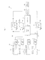
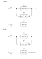
- Fig. 1 is a block diagram illustrating a configuration of a battery management system according to an embodiment of the present invention.
- a battery management system 101 includes a plurality of battery packs 110, a plurality of slave battery management units 120, a master battery management unit 130, a current sensor 131, a first main relay 141, a first sub relay 142 and a second main relay 151.
- the battery management system 101 according to the present invention may further includes a safety switch 161 and a safety fuse 162.
- the battery management system 101 according to the present invention may further includes a controller 170, an inverter 180 and a motor generator 190.
- Each of the plurality of battery packs 110 includes a plurality of battery cells 111.
- the battery cells 111 may be connected to each other in series and/or in parallel.
- the plurality of battery packs 110 may also be connected to each other in series and/or in parallel.
- Each of the battery cells 111 may be one selected from the group consisting of a lithium ion battery, a lithium polymer battery and equivalents thereof, but not limited thereto.
- fuel cells, solar cells or a wind power generator may also be used in the present invention.
- the plurality of slave battery management units 120 are electrically connected to the corresponding battery packs 110, respectively, sense voltages and/or temperatures of the battery packs 110, and manage charging, discharging and/or cell balancing of the battery packs 110.
- One of the slave battery management units 120 manages one of the battery packs 110.
- the slave battery management units 120 may be electrically connected to each other in a controller area network (CAN) manner, but aspects of the present invention are not limited thereto.
- the slave battery management units 120 may be electrically connected to each other in a serial communication manner, such as RS232, RS422 or IEEE1394.
- the master battery management unit 130 is electrically connected to the slave battery management units 120, and manages the overall charging, discharging and/or pack balancing of all of the battery packs 110 based on the voltages and/or temperatures of the battery packs 110, transmitted from the respective slave battery management units 120.
- the master battery management unit 130 manages the battery packs 110 to allow over-current to be applied thereto or to prevent over-current from being output therefrom, using the current values obtained from the current sensor 131.
- the master battery management unit 130 directly controls turned-on and/or turned-off states of the first main relay 141, the first sub relay 142, the second main relay 151 and the second sub relay 152.
- the current sensor 131 is electrically connected between the battery packs 110 and a load (i.e., the inverter 180), senses the current input (charged) to the battery packs 110 and/or the current output (discharged) from the battery packs 110 and transmits the sensed current to the master battery management unit 130.
- the current sensor 131 may be one selected from the group consisting of a hall sensor, a shunt resistor, and equivalents thereof, but aspects of the present invention are not limited thereto.
- the first main relay 141 is electrically connected between positive electrodes of the battery packs 110 and the load (i.e., the inverter 180).
- the first main relay 141 is maintained at a turned-on state when the battery packs 110 are in normal states. However, when the battery packs 110 are in abnormal states, such as over-charge, over-discharge and/or over-current states, the first main relay 141 is turned off. To this end, the first main relay 141 is turned on and/or off by a control signal of the battery management unit 130. Further, the first main relay 141 may be turned on and/or off by a control signal of the inverter controller 170 controlling the inverter 180 or an air bag controller (not shown) controlling an air bag.
- the first main relay 141 is primarily turned on and/or off by the inverter controller 170, and is secondarily turned on and/or off by the master battery management unit 130 when the inverter controller 170 is broken.
- the first main relay 141 may be turned any time on and/or off by the control signal of the air bag controller.
- the first sub relay 142 includes a resistor R and is connected to the first main relay 141 in parallel.
- the resistor R is connected to the first sub relay 142 in series. While the first sub relay 142 is maintained at a turned-off state when the battery packs 110 are in normal states, it is first maintained in a turned-on state for a predetermined time before the first main relay 141 is turned off. In practice, the first sub relay 142 may first be maintained in a turned-on state to preliminarily charge the battery packs 110 when the battery packs 110 are over-discharged. Of course, when the preliminarily charging of the battery packs 110 is completed, the first sub relay 142 is turned off, and the first main relay 141 is turned on. Like the above- described first main relay 141, the first sub relay 142 is also turned on and/or off by the control signal of the battery management unit 130.
- the first sub relay 142 may also be turned on and/or off by the control signal of the inverter controller 170 controlling the inverter 180 or an air bag controller (not shown) controlling an air bag.
- the first sub relay 142 may be primarily turned on and/or off by the inverter controller 170, and may be secondarily turned on and/or off by the master battery management unit 130 when the inverter controller 170 is broken.
- the first sub relay 142 may be turned any time on and/or off by the control signal of the air bag controller.
- the second main relay 151 is electrically connected between negative electrodes of the battery packs 110 and the load (i.e., the inverter 180).
- the second main relay 151 is maintained at a turned-on state when the battery packs 110 are in normal states. However, when the battery packs 110 are in abnormal states, such as over-charge, over-discharge and/or over-current states, the second main relay 151 is turned off. To this end, the second main relay 151 is turned on and/or off by the control signal of the battery management unit 130. Further, the second main relay 151 may be turned on and/or off by the control signal of the inverter controller 170 controlling the inverter 180 or the air bag controller (not shown) controlling an air bag.
- the second main relay 151 is primarily turned on and/or off by the inverter controller 170, and is secondarily turned on and/or off by the master battery management unit 130 when the inverter controller 170 is broken.
- the second main relay 151 may be turned any time on and/or off by the control signal of the air bag controller.
- the safety switch 161 is electrically connected between the battery packs 110, and may be turned off by an operator when the breakdown of the battery management system 101 is fixed or the battery management is examined. Thus, if the safety switch 161 is turned off during fixing of the breakdown of the battery management system 101 or examination of the battery management, a risk of high current flowing through the operator can be avoided.
- the safety fuse 162 is electrically connected between the battery packs 110 and the load (i.e., the inverter 180), and is melted and blocks the flow of current when over-current exceeding reference current flows, thereby preventing the battery management system 101 from being damaged.
- the controller 170 is electrically connected to the master battery management unit 130 and controls the inverter 180 based on information obtained from the master battery management unit 130.
- information on a user's accelerator pedal open angle and/or brake pedal open angle may be input to the controller 170, so that the inverter 180 is controlled by the controller 170, which is, however, irrelevant to the contents of the present invention, and a detailed description thereof will be omitted.
- the controller 170 is also referred to as a motor control unit or a hybrid control unit.
- the inverter 180 is electrically connected to the first main relay 141, the first sub relay 142 and the second main relay 151.
- the inverter 180 converts power supplied from the battery packs 110 into a predetermined level of power when a vehicle accelerates, and transmits the converted power to the motor generator 190 or the power obtained from the motor generator 190 when vehicle decelerates to the battery packs 110. That is to say, the inverter 180 operates in two ways.
- the motor generator 190 is electrically connected to the inverter 180 to provide a thrust to the vehicle or to provide power to the battery packs 110 when the vehicle decelerates.
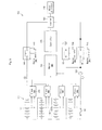
- Fig. 2 is a block diagram illustrating a configuration of a battery management system according to another embodiment of the present invention.
- the battery management system 102 shown in FIG. 2 is substantially the same as the battery management system 101 shown in FIG. 1 , except for connected locations of sub relays. That is to say, as illustrated in FIG. 2 , in the battery management system 102, second main relay 151 is electrically connected between negative electrodes of the battery packs 110 and the load (i.e., the inverter 180), and the second sub relay 152 is electrically connected to the second main relay 151 in parallel. A resistor R is connected to the second sub relay 152 in series.
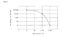
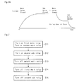
- Fig. 3 is a graph illustrating the relationship between the load current and life of a relay.
- the X axis indicates load current (A)
- the Y axis indicates estimated life (cycles) of a relay.
- the cycle means the number of the relay turned on and/or off.
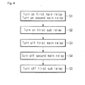
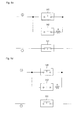
- Fig. 4 is a flowchart illustrating a driving method of a battery management system according to an embodiment of the present invention.
- FIG. 4 illustrates a driving method of the battery management system 101 shown in FIG. 1 .
- the driving method is a method for switching from a state in which the battery packs 110 and the load (i.e., the inverter 180) are electrically connected to each other to a state in which the battery packs 110 and the load are electrically disconnected from each other.
- the driving method according to the present invention includes turning on first and second main relays (S1), turning on a first sub relay (S2), turning off the first main relay (S3), turning off the second main relay (S4) and turning off the first sub relay (S5).
- Figs. 5a to 5e sequentially illustrate a driving method of a battery management system according to an embodiment of the present invention.
- the driving method of the battery management system 101 according to the present invention will now be described with reference to Figs. 5a to 5e together with Fig. 4 .
- the controlling is done by the controller 170, the master battery management unit 130 or the air bag controller.
- the controller 170 has primary control capacity, and when the controller 170 cannot properly perform a control operation, the master battery management unit 130 has primary control capacity.
- the air bag controller has primary control capacity.
- step S1 as illustrated in Fig. 5a , the first main relay 141 and the second main relay 151 are turned on, thereby electrically connecting the battery packs 110 and the load (i.e., the inverter 180).
- the first sub relay 142 is maintained in a turned-off state, which is maintained while the battery packs 110 are normally charged and/or discharged.
- step S2 as illustrated in Fig. 5b , the first sub relay 142 is turned on, thereby reducing the current flowing through the first main relay 141. That is to say, before the first sub relay 142 is turned on, the current flows through only the first main relay 141. However, as the first sub relay 142 is turned on, the current flowing through the first main relay 141 is reduced. This state is initiated when the battery packs 110 are abnormally charged and/or discharged, when over-current exceeding a reference current level flows, or when the air bag is activated.
- step S3 as illustrated in Fig. 5c , the first main relay 141 connected to the first sub relay 142 in parallel is turned off.
- the first sub relay 142 connected to the first main relay 141 in parallel is turned on, even if the first main relay 141 is turned off, the current between the positive electrodes of the battery packs 110 and the load (i.e., the inverter 180) is not sharply reduced. That is to say, even if the first main relay 141 is turned off, a predetermined level of current flows through the first sub relay 142 since the first sub relay 142 having the resistor R is turned on.
- step S4 as illustrated in Fig. 5d , the second main relay 151 is turned off, thereby blocking an electrical path between the negative electrodes of the battery packs 110 and the load (i.e., the inverter 180).
- step S5 as illustrated in Fig. 5e , the first sub relay 142 is turned off, thereby blocking an electrical path between the positive electrodes of the battery packs 110 and the load (i.e., the inverter 180). In such a manner, the electrical path between the battery packs 110 and the load (i.e., the inverter 180) is completely blocked.
- the first main relay 141 connected the positive electrodes of the battery packs 110 and the load is turned off (opened)
- the current is slowly reduced, thereby preventing arcing and spiking from occurring and ultimately efficiently preventing fusion of the first main relay 141. That is to say, according to the present invention, before the first main relay 141 is turned off (opened), the first sub relay 142 having the resistor R is first turned on (closed), the first main relay 141 is then turned off, and the first sub relay 142 is finally turned off, to reduce the current step by step, thereby preventing arcing and spiking from occurring to the first main relay 141 and ultimately preventing fusion of the first main relay 141.
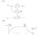
- Fig. 6A is a graph illustrating the relationship between the time and current of a main relay when the main relay is turned off
- Fig. 6B is a graph illustrating the relationship between the time and the total current flowing through the main relay, the first sub relay and the resistor when the main relay is turned off after a sub relay is turned on.
- a main relay in a case where a main relay is directly turned off (opened) in a state in which there is no sub relay, the current is rapidly reduced for a predetermined time, thereby increasing the risk of arcing and spiking occurring to the main relay.
- the main relays may be fused.
- the current is reduced step by step for a predetermined time, so that the risk of arcing and spiking occurring to the main relay may be reduced, thereby lowering a probability of the main relay being fused.
- Fig. 7 is a flowchart illustrating a driving method of a battery management system according to another embodiment of the present invention. That is to say, Fig. 7 illustrates a driving method of the battery management system 102 shown in FIG. 2 .
- the driving method according to the present invention includes turning on first and second main relays (S11), turning on a second sub relay (S12), turning off the second main relay (S13), turning off the first main relay (S14) and turning off the second sub relay (S15).
- Figs. 8a to 8e illustrate a sequence of turning off relays in a battery management system according to an embodiment of the present invention.
- the driving method of the battery management system 102 according to the present invention will now be described with reference to Figs. 8a to 8e together with Fig. 7 .
- step S11 as illustrated in Fig. 8a , the first main relay 141 and the second main relay 151 are turned on, thereby electrically connecting the battery packs 110 and the load (i.e., the inverter 180).
- the second sub relay 152 is maintained in a turned-off state.
- step S12 as illustrated in Fig. 8b , the second sub relay 152 is turned on, thereby reducing the current flowing through the second main relay 151. That is to say, before the second sub relay 152 is turned on, the current flows through only the second main relay 151. However, as the second sub relay 152 is turned on, the current flowing through the second main relay 151 is reduced.
- step S13 as illustrated in Fig. 8c , the second main relay 151 connected to the first sub relay 142 in parallel is turned off.
- the second sub relay 152 connected to the second main relay 151 in parallel is turned on, even if the second main relay 151 is turned off, the current between the battery packs 110 and the load (i.e., the inverter 180) is not sharply reduced. That is to say, even if the second main relay 151 is turned off, current still flows through the second sub relay 152.
- step S14 as illustrated in Fig. 8d , the first main relay 141 is turned off, thereby blocking an electrical path between the positive electrodes of the battery packs 110 and the load (i.e., the inverter 180).
- step S15 as illustrated in Fig. 8e , the second sub relay 152 is turned off, thereby blocking an electrical path between the negative electrodes of the battery packs 110 and the load (i.e., the inverter 180). In such a manner, the electrical path between the battery packs 110 and the load (i.e., the inverter 180) is completely blocked.
- the second main relay 151 connected the negative electrodes of the battery packs 110 and the load is turned off (opened)
- the current is slowly reduced, thereby preventing arcing and spiking from occurring and ultimately efficiently preventing fusion of the second main relay 151. That is to say, according to the present invention, before the second main relay 151 is turned off (opened), the second sub relay 152 having the resistor R is first turned on (closed), the second main relay 151 is then turned off, and the second sub relay 152 is finally turned off, to reduce the current step by step, thereby preventing arcing and spiking from occurring to the second main relay 151 and ultimately preventing fusion of the second main relay 151.
- the illustrated embodiments have been described with regard to the cases where the first sub relay having the resistor is connected to the first main relay in parallel and where the second sub relay having the resistor is connected to the second main relay in parallel, respectively, the cases may also be simultaneously implemented by the present invention using a single circuit.
- the present invention can implement a circuit in which the second sub relay having the resistor is connected to the second main relay in parallel while the first sub relay having the resistor is connected to the first main relay in parallel.
- the first main relay may be turned off
- the second sub relay may be turned off
- the second main relay may be turned off
- the first main relay may be turned off.
- the first and second sub relays are turned off, thereby preventing arcing and spiking from occurring to the first and second sub relays, and preventing the first and second sub relays from being fused.
Abstract
Description
- Embodiments of the present invention relate to a battery management system and a driving method thereof.
- Vehicles using the internal combustion engine using gasoline or diesel oil as vehicle fuel release harmful exhaust gases considered to be one of the primary causes of air pollution. Accordingly, in recent years, in order to decrease environmental pollution, attempts to develop electric vehicles and hybrid vehicles have been actively undertaken.
- An electric vehicle has an electric motor that is powered by a battery pack including a plurality of rechargeable secondary battery cells. Since an electric vehicle uses a battery pack as a main power source, exhaust gas is not generated and little noise is produced. In addition, a hybrid vehicle is an intermediate stage between a conventional internal combustion engine vehicle and an electric vehicle. A hybrid vehicle uses two or more power sources, for example, an internal combustion engine and a battery-powered motor.
- In the vehicle using electrical energy, battery performance directly affects performance of the vehicle. Thus, each battery cell should have excellent performance, and there is a need for a battery management system capable of efficiently managing charging and discharging of each battery cell by measuring voltages of battery cells, the voltage, current and temperature of the entire battery pack.
- Meanwhile, the battery management system includes a plurality of relays for supplying power from a battery to a motor, supplying power from a generator to a battery, or blocking power supply in an emergent situation. The relays are subjected to severe stress when they are turned off (opened) in a case where current flows, rather than in a case where current does not flow. In particular, when the relays are turned off in a current flowing situation, the relays may often be melted as arcing and spiking occur to the relay.
- It is a feature of an embodiment to provide a battery management system and a driving method thereof are provided, which can prevent fusion of a relay by preventing arcing and spiking when the relay is turned off.
- In accordance with an embodiment of the present invention, there is provided a battery management system including: one or more battery packs; a master battery management unit, a master battery management unit sensing voltages and/or currents of the battery packs; main relays connected between the battery packs and loads and turned on or off by the master battery management unit; and sub relays connected to the main relays in parallel, turned on or off by the master battery management unit and having resistors, wherein when switching occurs from a state in which the battery packs and the loads are electrically connected to a state in which the battery packs and the loads are electrically disconnected, the sub relays are first turned on and the main relays are then turned off.
- In the battery management system, after the main relay is turned off, the sub relay may then be turned off.
- The resistor may be connected to the sub relay in series.
- The main relay may be connected between the positive electrodes of the battery packs and the load.
- The main relay may be connected between the negative electrodes of the battery packs and the load.
- The load may be an inverter, a controller controlling the inverter may be connected between the master battery management unit and the inverter, and the main relay and the sub relay may be turned on or off by the controller.
- In accordance with another embodiment of the present invention, there is provided a driving method of a battery management system including: one or more battery packs; a master battery management unit, a master battery management unit sensing voltages and/or currents of the battery packs; main relays connected between the battery packs and loads and turned on or off by the master battery management unit; and sub relays connected to the main relays in parallel, turned on or off by the master battery management unit and having resistors, wherein when switching occurs from a state in which the battery packs and the loads are electrically connected to a state in which the battery packs and the loads are electrically disconnected, the sub relays are first turned on and the main relays are then turned off.
- At least some of the above and other features of the invention are set out in the claims.
- Embodiments of the present invention provide a battery management system and a driving method thereof, which can prevent fusion of a relay by preventing arcing and spiking when the relay is turned off.
- In addition, according to the present invention, before the main relay is turned off, the sub relay having a resistor is first turned on (closed), the main relay is then turned off and the sub relay is finally turned off, so that the current of the main relay decreases step by step, thereby preventing arcing and spiking from occurring to the main relay. Accordingly, it is possible to prevent the main relay from being fused.
-
-
Fig. 1 is a block diagram illustrating a configuration of a battery management system according to an embodiment of the present invention; -
Fig. 2 is a block diagram illustrating a configuration of a battery management system according to another embodiment of the present invention; -
Fig. 3 is a graph illustrating the relationship between the load current and life of a relay; -
Fig. 4 is a flowchart illustrating a driving method of a battery management system according to an embodiment of the present invention; -
Figs. 5a to 5e sequentially illustrate a driving method of a battery management system according to an embodiment of the present invention; -
Fig. 6A is a graph illustrating the relationship between the time and current of a main relay when the main relay is turned off, andFig. 6B is a graph illustrating the relationship between the time and current when the main relay is turned off after a sub relay is turned on; -
Fig. 7 is a flowchart illustrating a driving method of a battery management system according to another embodiment of the present invention; and -
Figs. 8a to 8e illustrate a sequence of turning off relays in a battery management system according to an embodiment of the present invention. - Hereinafter, examples of embodiments of the invention will be described in detail with reference to the accompanying drawings such that they can easily be made and used by those skilled in the art.
- Example embodiments of the invention will now be described more fully hereinafter with reference to the accompanying drawings; however, they may be embodied in different forms and should not be construed as limited to the embodiments of the invention set forth herein. Rather, these embodiments of the invention are provided so that this disclosure will be thorough and complete, and will fully convey the scope of the disclosure to those skilled in the art.
- In addition, in the drawing figures, the dimensions of layers and regions may be exaggerated for clarity of illustration. In the drawing figures, like reference numerals refer to like elements throughout. As used herein, the term "and/or" includes any and all combinations of one or more of the associated listed items.
- The terminology used herein is for the purpose of describing particular embodiments only and is not intended to be limiting of the invention. As used herein, the singular forms are intended to include the plural forms as well, unless the context clearly indicates otherwise. It will be further understood that the terms "comprise" and/or "comprising," when used in this specification, specify the presence of stated features, integers, steps, operations, elements, and/or components, but do not preclude the presence or addition of one or more other features, integers, steps, operations, elements, components, and/or groups thereof.
- It will be understood that, although the terms first, second, etc. may be used herein to describe various elements, these elements should not be limited by these terms. These terms are only used to distinguish one element from another element. Thus, for example, a first element, a first component or a first section discussed below could be termed a second element, a second component or a second section without departing from the teachings of the present invention.
- In addition, as used herein, the term "relay" is used to include an electromagnetic relay, for example, a DC electromagnetic relay, an AC electromagnetic relay, a magnetic latching relay, a polarized relay, a reed relay, or the like. Further, as used herein, the term "relay" is used to include a device capable of controlling a relatively large electric signal using a relatively small electric signal, but the present invention does not limit the kind of the relay to those listed herein.
-
Fig. 1 is a block diagram illustrating a configuration of a battery management system according to an embodiment of the present invention. - As illustrated in
Fig. 1 , abattery management system 101 according to the present invention includes a plurality ofbattery packs 110, a plurality of slavebattery management units 120, a masterbattery management unit 130, acurrent sensor 131, a firstmain relay 141, afirst sub relay 142 and a secondmain relay 151. In addition, thebattery management system 101 according to the present invention may further includes asafety switch 161 and asafety fuse 162. Moreover, thebattery management system 101 according to the present invention may further includes acontroller 170, aninverter 180 and amotor generator 190. - Each of the plurality of
battery packs 110 includes a plurality ofbattery cells 111. Thebattery cells 111 may be connected to each other in series and/or in parallel. In addition, the plurality ofbattery packs 110 may also be connected to each other in series and/or in parallel. Each of thebattery cells 111 may be one selected from the group consisting of a lithium ion battery, a lithium polymer battery and equivalents thereof, but not limited thereto. In addition to the battery packs 110, fuel cells, solar cells or a wind power generator may also be used in the present invention. - The plurality of slave
battery management units 120 are electrically connected to the corresponding battery packs 110, respectively, sense voltages and/or temperatures of the battery packs 110, and manage charging, discharging and/or cell balancing of the battery packs 110. One of the slavebattery management units 120 manages one of the battery packs 110. In addition, the slavebattery management units 120 may be electrically connected to each other in a controller area network (CAN) manner, but aspects of the present invention are not limited thereto. For example, the slavebattery management units 120 may be electrically connected to each other in a serial communication manner, such as RS232, RS422 or IEEE1394. - The master
battery management unit 130 is electrically connected to the slavebattery management units 120, and manages the overall charging, discharging and/or pack balancing of all of the battery packs 110 based on the voltages and/or temperatures of the battery packs 110, transmitted from the respective slavebattery management units 120. In addition, the masterbattery management unit 130 manages the battery packs 110 to allow over-current to be applied thereto or to prevent over-current from being output therefrom, using the current values obtained from thecurrent sensor 131. Further, the masterbattery management unit 130 directly controls turned-on and/or turned-off states of the firstmain relay 141, thefirst sub relay 142, the secondmain relay 151 and thesecond sub relay 152. - The
current sensor 131 is electrically connected between the battery packs 110 and a load (i.e., the inverter 180), senses the current input (charged) to the battery packs 110 and/or the current output (discharged) from the battery packs 110 and transmits the sensed current to the masterbattery management unit 130. Thecurrent sensor 131 may be one selected from the group consisting of a hall sensor, a shunt resistor, and equivalents thereof, but aspects of the present invention are not limited thereto. - The first
main relay 141 is electrically connected between positive electrodes of the battery packs 110 and the load (i.e., the inverter 180). The firstmain relay 141 is maintained at a turned-on state when the battery packs 110 are in normal states. However, when the battery packs 110 are in abnormal states, such as over-charge, over-discharge and/or over-current states, the firstmain relay 141 is turned off. To this end, the firstmain relay 141 is turned on and/or off by a control signal of thebattery management unit 130. Further, the firstmain relay 141 may be turned on and/or off by a control signal of theinverter controller 170 controlling theinverter 180 or an air bag controller (not shown) controlling an air bag. In practice, the firstmain relay 141 is primarily turned on and/or off by theinverter controller 170, and is secondarily turned on and/or off by the masterbattery management unit 130 when theinverter controller 170 is broken. The firstmain relay 141 may be turned any time on and/or off by the control signal of the air bag controller. - The
first sub relay 142 includes a resistor R and is connected to the firstmain relay 141 in parallel. The resistor R is connected to thefirst sub relay 142 in series. While thefirst sub relay 142 is maintained at a turned-off state when the battery packs 110 are in normal states, it is first maintained in a turned-on state for a predetermined time before the firstmain relay 141 is turned off. In practice, thefirst sub relay 142 may first be maintained in a turned-on state to preliminarily charge the battery packs 110 when the battery packs 110 are over-discharged. Of course, when the preliminarily charging of the battery packs 110 is completed, thefirst sub relay 142 is turned off, and the firstmain relay 141 is turned on. Like the above- described firstmain relay 141, thefirst sub relay 142 is also turned on and/or off by the control signal of thebattery management unit 130. - In addition, like the above- described first
main relay 141, thefirst sub relay 142 may also be turned on and/or off by the control signal of theinverter controller 170 controlling theinverter 180 or an air bag controller (not shown) controlling an air bag. - In addition, the
first sub relay 142 may be primarily turned on and/or off by theinverter controller 170, and may be secondarily turned on and/or off by the masterbattery management unit 130 when theinverter controller 170 is broken. Thefirst sub relay 142 may be turned any time on and/or off by the control signal of the air bag controller. - The second
main relay 151 is electrically connected between negative electrodes of the battery packs 110 and the load (i.e., the inverter 180). The secondmain relay 151 is maintained at a turned-on state when the battery packs 110 are in normal states. However, when the battery packs 110 are in abnormal states, such as over-charge, over-discharge and/or over-current states, the secondmain relay 151 is turned off. To this end, the secondmain relay 151 is turned on and/or off by the control signal of thebattery management unit 130. Further, the secondmain relay 151 may be turned on and/or off by the control signal of theinverter controller 170 controlling theinverter 180 or the air bag controller (not shown) controlling an air bag. In practice, the secondmain relay 151 is primarily turned on and/or off by theinverter controller 170, and is secondarily turned on and/or off by the masterbattery management unit 130 when theinverter controller 170 is broken. The secondmain relay 151 may be turned any time on and/or off by the control signal of the air bag controller. - The
safety switch 161 is electrically connected between the battery packs 110, and may be turned off by an operator when the breakdown of thebattery management system 101 is fixed or the battery management is examined. Thus, if thesafety switch 161 is turned off during fixing of the breakdown of thebattery management system 101 or examination of the battery management, a risk of high current flowing through the operator can be avoided. - The
safety fuse 162 is electrically connected between the battery packs 110 and the load (i.e., the inverter 180), and is melted and blocks the flow of current when over-current exceeding reference current flows, thereby preventing thebattery management system 101 from being damaged. - The
controller 170 is electrically connected to the masterbattery management unit 130 and controls theinverter 180 based on information obtained from the masterbattery management unit 130. Here, information on a user's accelerator pedal open angle and/or brake pedal open angle may be input to thecontroller 170, so that theinverter 180 is controlled by thecontroller 170, which is, however, irrelevant to the contents of the present invention, and a detailed description thereof will be omitted. Meanwhile, thecontroller 170 is also referred to as a motor control unit or a hybrid control unit. - The
inverter 180 is electrically connected to the firstmain relay 141, thefirst sub relay 142 and the secondmain relay 151. Theinverter 180 converts power supplied from the battery packs 110 into a predetermined level of power when a vehicle accelerates, and transmits the converted power to themotor generator 190 or the power obtained from themotor generator 190 when vehicle decelerates to the battery packs 110. That is to say, theinverter 180 operates in two ways. - The
motor generator 190 is electrically connected to theinverter 180 to provide a thrust to the vehicle or to provide power to the battery packs 110 when the vehicle decelerates. -
Fig. 2 is a block diagram illustrating a configuration of a battery management system according to another embodiment of the present invention. - The
battery management system 102 shown inFIG. 2 is substantially the same as thebattery management system 101 shown inFIG. 1 , except for connected locations of sub relays. That is to say, as illustrated inFIG. 2 , in thebattery management system 102, secondmain relay 151 is electrically connected between negative electrodes of the battery packs 110 and the load (i.e., the inverter 180), and thesecond sub relay 152 is electrically connected to the secondmain relay 151 in parallel. A resistor R is connected to thesecond sub relay 152 in series. -
Fig. 3 is a graph illustrating the relationship between the load current and life of a relay. InFIG. 3 , the X axis indicates load current (A), and the Y axis indicates estimated life (cycles) of a relay. Here, the cycle means the number of the relay turned on and/or off. - As illustrated in
FIG. 3 , even for relays of the same capacity, the higher the load current, the shorter the estimated life, and the lower the load current, the longer the estimated life. Thus, in order to increase the life of a relay, it is necessary to reduce the load current when the relay is turned on and/or off. In particular, compared to a case where the relay is turned on, in a case where the relay is turned off, relatively severe stress is applied to the relay. Therefore, it is necessary to reduce the load current when the relay is turned off. -
Fig. 4 is a flowchart illustrating a driving method of a battery management system according to an embodiment of the present invention. -
FIG. 4 illustrates a driving method of thebattery management system 101 shown inFIG. 1 . The driving method is a method for switching from a state in which the battery packs 110 and the load (i.e., the inverter 180) are electrically connected to each other to a state in which the battery packs 110 and the load are electrically disconnected from each other. - As illustrated in
FIG. 4 , the driving method according to the present invention includes turning on first and second main relays (S1), turning on a first sub relay (S2), turning off the first main relay (S3), turning off the second main relay (S4) and turning off the first sub relay (S5). -
Figs. 5a to 5e sequentially illustrate a driving method of a battery management system according to an embodiment of the present invention. The driving method of thebattery management system 101 according to the present invention will now be described with reference toFigs. 5a to 5e together withFig. 4 . Here, the controlling is done by thecontroller 170, the masterbattery management unit 130 or the air bag controller. In practice, thecontroller 170 has primary control capacity, and when thecontroller 170 cannot properly perform a control operation, the masterbattery management unit 130 has primary control capacity. In addition, as soon as the air bag is activated, the air bag controller has primary control capacity. - In step S1, as illustrated in
Fig. 5a , the firstmain relay 141 and the secondmain relay 151 are turned on, thereby electrically connecting the battery packs 110 and the load (i.e., the inverter 180). Here, thefirst sub relay 142 is maintained in a turned-off state, which is maintained while the battery packs 110 are normally charged and/or discharged. - In step S2, as illustrated in
Fig. 5b , thefirst sub relay 142 is turned on, thereby reducing the current flowing through the firstmain relay 141. That is to say, before thefirst sub relay 142 is turned on, the current flows through only the firstmain relay 141. However, as thefirst sub relay 142 is turned on, the current flowing through the firstmain relay 141 is reduced. This state is initiated when the battery packs 110 are abnormally charged and/or discharged, when over-current exceeding a reference current level flows, or when the air bag is activated. - In step S3, as illustrated in
Fig. 5c , the firstmain relay 141 connected to thefirst sub relay 142 in parallel is turned off. Here, since thefirst sub relay 142 connected to the firstmain relay 141 in parallel is turned on, even if the firstmain relay 141 is turned off, the current between the positive electrodes of the battery packs 110 and the load (i.e., the inverter 180) is not sharply reduced. That is to say, even if the firstmain relay 141 is turned off, a predetermined level of current flows through thefirst sub relay 142 since thefirst sub relay 142 having the resistor R is turned on. - In step S4, as illustrated in
Fig. 5d , the secondmain relay 151 is turned off, thereby blocking an electrical path between the negative electrodes of the battery packs 110 and the load (i.e., the inverter 180). - In step S5, as illustrated in
Fig. 5e , thefirst sub relay 142 is turned off, thereby blocking an electrical path between the positive electrodes of the battery packs 110 and the load (i.e., the inverter 180). In such a manner, the electrical path between the battery packs 110 and the load (i.e., the inverter 180) is completely blocked. - Therefore, in the
battery management system 101 and the driving method thereof according to the present invention, when the firstmain relay 141 connected the positive electrodes of the battery packs 110 and the load is turned off (opened), the current is slowly reduced, thereby preventing arcing and spiking from occurring and ultimately efficiently preventing fusion of the firstmain relay 141. That is to say, according to the present invention, before the firstmain relay 141 is turned off (opened), thefirst sub relay 142 having the resistor R is first turned on (closed), the firstmain relay 141 is then turned off, and thefirst sub relay 142 is finally turned off, to reduce the current step by step, thereby preventing arcing and spiking from occurring to the firstmain relay 141 and ultimately preventing fusion of the firstmain relay 141. -
Fig. 6A is a graph illustrating the relationship between the time and current of a main relay when the main relay is turned off, andFig. 6B is a graph illustrating the relationship between the time and the total current flowing through the main relay, the first sub relay and the resistor when the main relay is turned off after a sub relay is turned on. - As illustrated in
Fig. 6a , in a case where a main relay is directly turned off (opened) in a state in which there is no sub relay, the current is rapidly reduced for a predetermined time, thereby increasing the risk of arcing and spiking occurring to the main relay. Thus, the main relays may be fused. - However, as illustrated in
Fig. 6b , in a case where the main relay is turned off and the sub relay is finally turned off in a state in which the sub relay is turned on, the current is reduced step by step for a predetermined time, so that the risk of arcing and spiking occurring to the main relay may be reduced, thereby lowering a probability of the main relay being fused. -
Fig. 7 is a flowchart illustrating a driving method of a battery management system according to another embodiment of the present invention. That is to say,Fig. 7 illustrates a driving method of thebattery management system 102 shown inFIG. 2 . - As illustrated in
FIG. 7 , the driving method according to the present invention includes turning on first and second main relays (S11), turning on a second sub relay (S12), turning off the second main relay (S13), turning off the first main relay (S14) and turning off the second sub relay (S15). -
Figs. 8a to 8e illustrate a sequence of turning off relays in a battery management system according to an embodiment of the present invention. The driving method of thebattery management system 102 according to the present invention will now be described with reference toFigs. 8a to 8e together withFig. 7 . - In step S11, as illustrated in
Fig. 8a , the firstmain relay 141 and the secondmain relay 151 are turned on, thereby electrically connecting the battery packs 110 and the load (i.e., the inverter 180). Here, thesecond sub relay 152 is maintained in a turned-off state. - In step S12, as illustrated in
Fig. 8b , thesecond sub relay 152 is turned on, thereby reducing the current flowing through the secondmain relay 151. That is to say, before thesecond sub relay 152 is turned on, the current flows through only the secondmain relay 151. However, as thesecond sub relay 152 is turned on, the current flowing through the secondmain relay 151 is reduced. - In step S13, as illustrated in
Fig. 8c , the secondmain relay 151 connected to thefirst sub relay 142 in parallel is turned off. Here, since thesecond sub relay 152 connected to the secondmain relay 151 in parallel is turned on, even if the secondmain relay 151 is turned off, the current between the battery packs 110 and the load (i.e., the inverter 180) is not sharply reduced. That is to say, even if the secondmain relay 151 is turned off, current still flows through thesecond sub relay 152. - In step S14, as illustrated in
Fig. 8d , the firstmain relay 141 is turned off, thereby blocking an electrical path between the positive electrodes of the battery packs 110 and the load (i.e., the inverter 180). - In step S15, as illustrated in
Fig. 8e , thesecond sub relay 152 is turned off, thereby blocking an electrical path between the negative electrodes of the battery packs 110 and the load (i.e., the inverter 180). In such a manner, the electrical path between the battery packs 110 and the load (i.e., the inverter 180) is completely blocked. - Therefore, in the
battery management system 102 and the driving method thereof according to the present invention, when the secondmain relay 151 connected the negative electrodes of the battery packs 110 and the load is turned off (opened), the current is slowly reduced, thereby preventing arcing and spiking from occurring and ultimately efficiently preventing fusion of the secondmain relay 151. That is to say, according to the present invention, before the secondmain relay 151 is turned off (opened), thesecond sub relay 152 having the resistor R is first turned on (closed), the secondmain relay 151 is then turned off, and thesecond sub relay 152 is finally turned off, to reduce the current step by step, thereby preventing arcing and spiking from occurring to the secondmain relay 151 and ultimately preventing fusion of the secondmain relay 151. - Meanwhile, the illustrated embodiments have been described with regard to the cases where the first sub relay having the resistor is connected to the first main relay in parallel and where the second sub relay having the resistor is connected to the second main relay in parallel, respectively, the cases may also be simultaneously implemented by the present invention using a single circuit.
- That is to say, the present invention can implement a circuit in which the second sub relay having the resistor is connected to the second main relay in parallel while the first sub relay having the resistor is connected to the first main relay in parallel. In this case, after the first sub relay is turned on, the first main relay may be turned off, and after the second sub relay is turned on, the second main relay may be turned off. In addition, after the second sub relay is turned on, the second main relay may be turned off, or after the first sub relay is turned on, the first main relay may be turned off. In addition, after the operations stated above, the first and second sub relays are turned off, thereby preventing arcing and spiking from occurring to the first and second sub relays, and preventing the first and second sub relays from being fused.
- While the battery management system and the driving method thereof according to the invention has been described in connection with certain embodiments of the invention, it will be understood by those skilled in the art that the invention is not limited to the disclosed embodiment, but rather is intended to cover various modifications included within the scope of the appended claims and equivalents thereof.
Claims (15)
- A battery management system comprising:a battery pack;a first main relay connected between the battery pack and a load;a first sub relay connected between the battery pack and the load and in parallel with the first main relay; andcontrol means adapted to operate the first main relay and the first sub relay;wherein the control means is adapted to turn the first main relay off when the first sub relay is turned on, in the event that the battery pack is to be electrically disconnected from the load.
- A battery management system according to claim 1, wherein the control means is adapted to turn the first main relay off only when the first sub relay is turned on.
- A battery management system according to claim 1 or 2, wherein the control means is adapted to turn on the first sub relay prior to turning off the first main relay.
- A battery management system according to any preceding claim, wherein the control means is adapted to turn off the first sub relay after turning off the first main relay.
- A battery management system according to any preceding claim, wherein the control means comprises a master battery management unit that is adapted to respond to a voltage and/or current of the battery pack.
- A battery management system according to any preceding claim, wherein the load is an inverter and the control means comprises a controller that is adapted to control the inverter as well as the first main relay and the first sub relay.
- A battery management system according to any preceding claim, wherein the control means comprises an air-bag controller that is adapted to control the first main relay and the first sub relay in response to a condition of an air bag.
- A battery management system according to any preceding claim, further comprising a resistor connected in series with the first sub relay.
- A battery management system according to any preceding claim, wherein the first main relay and the first sub relay are connected between a positive electrode of the battery pack and the load.
- A battery management system according to one of claims 1 to 8, wherein the first main relay and the first sub relay are connected between a negative electrode of the battery pack and the load.
- A battery management system according to claim 9, further comprising a second main relay connected between the load and a negative electrode of the battery pack.
- A battery management system according to claim 10, further comprising a second main relay connected between the load and a positive electrode of the battery pack.
- A battery management system according to claim 11 or 12, further comprising a second sub relay connected between the battery pack and the load and in parallel with the second main relay, wherein the control means is adapted to turn the second main relay off when the second sub relay is turned on, in the event that the battery pack is to be electrically disconnected from the load.
- A driving method for a battery management system, which battery management system comprises:a battery pack;a first main relay connected between the battery pack and a load;a first sub relay connected between the battery pack and the load and in parallel with the first main relay; andcontrol means adapted to operate the first main relay and the first sub relay;wherein the control means turns the first main relay off when the first sub relay is turned on, in the event that the battery pack is to be electrically disconnected from the load.
- A driving method according to claim 14, further comprising a resistor connected in series with the first sub relay.
Applications Claiming Priority (2)
| Application Number | Priority Date | Filing Date | Title |
|---|---|---|---|
| US201361774374P | 2013-03-07 | 2013-03-07 | |
| US13/917,563 US10464507B2 (en) | 2013-03-07 | 2013-06-13 | Battery management system and switching method thereof |
Publications (3)
| Publication Number | Publication Date |
|---|---|
| EP2774798A2 true EP2774798A2 (en) | 2014-09-10 |
| EP2774798A3 EP2774798A3 (en) | 2015-09-23 |
| EP2774798B1 EP2774798B1 (en) | 2020-04-15 |
Family
ID=48747989
Family Applications (1)
| Application Number | Title | Priority Date | Filing Date |
|---|---|---|---|
| EP13175618.1A Active EP2774798B1 (en) | 2013-03-07 | 2013-07-08 | Battery management system and driving method thereof |
Country Status (6)
| Country | Link |
|---|---|
| US (1) | US10464507B2 (en) |
| EP (1) | EP2774798B1 (en) |
| JP (2) | JP6607659B2 (en) |
| KR (1) | KR101686280B1 (en) |
| CN (1) | CN104037460B (en) |
| HU (1) | HUE049823T2 (en) |
Cited By (3)
| Publication number | Priority date | Publication date | Assignee | Title |
|---|---|---|---|---|
| EP3354511A4 (en) * | 2016-06-22 | 2018-12-19 | LG Chem, Ltd. | Driving circuit for electric vehicle and control method therefor |
| EP3744557A1 (en) * | 2017-12-28 | 2020-12-02 | Yura Corporation Co., Ltd. | Power relay assembly for an electric vehicle and driving method thereof |
| EP3936373A1 (en) * | 2020-07-10 | 2022-01-12 | Volvo Truck Corporation | A control system for controlling an electric energy system of a vehicle |
Families Citing this family (33)
| Publication number | Priority date | Publication date | Assignee | Title |
|---|---|---|---|---|
| KR20140096600A (en) * | 2013-01-28 | 2014-08-06 | 삼성에스디아이 주식회사 | Battery Pack and method for cell balancing thereof |
| US10320202B2 (en) * | 2014-09-30 | 2019-06-11 | Johnson Controls Technology Company | Battery system bi-stable relay control |
| KR101684085B1 (en) * | 2015-04-06 | 2016-12-07 | 현대자동차주식회사 | Latching relay and high-voltage battery system for hybrid vehicle usging the same |
| US10396582B2 (en) * | 2015-07-01 | 2019-08-27 | Maxim Integrated Products, Inc. | Master slave charging architecture with communication between chargers |
| KR20170052095A (en) * | 2015-11-03 | 2017-05-12 | 현대자동차주식회사 | Battery control system and method for detecting fusion of relay |
| KR102528423B1 (en) * | 2015-12-09 | 2023-05-03 | 현대모비스 주식회사 | Battery Management System for reducing noise and method thereof |
| US10283982B2 (en) * | 2016-01-27 | 2019-05-07 | Gm Global Technology Operations Llc. | Voltage disconnect architecture |
| CN106627188B (en) * | 2016-03-23 | 2022-07-08 | 上海火亮新能源科技有限公司 | Electric automobile increases journey system |
| US10211657B2 (en) * | 2016-07-29 | 2019-02-19 | Robert Bosch Battery Systems GmbH | Smart contactor for battery disconnection unit |
| KR101907373B1 (en) * | 2016-11-16 | 2018-10-12 | 현대오트론 주식회사 | Apparatus and method for preventing over-charging |
| EP3549230B1 (en) * | 2016-11-30 | 2021-10-06 | Bombardier Recreational Products Inc. | Electric system and method for energizing the electric system |
| CN106532872A (en) * | 2016-12-31 | 2017-03-22 | 刘杰 | Matrix control method for multiple battery packs in communication base station |
| US10236802B2 (en) * | 2017-02-08 | 2019-03-19 | Premergy, Inc. | Adaptive regeneration systems for electric vehicles |
| US10992144B2 (en) * | 2017-05-17 | 2021-04-27 | Galley Power LLC | Battery balancing and current control with bypass circuit for load switch |
| DE102017215106B4 (en) * | 2017-08-30 | 2022-07-28 | Volkswagen Aktiengesellschaft | Means of locomotion, arrangement and device for evaluating a signal from an airbag control unit |
| CN109524945A (en) * | 2017-09-19 | 2019-03-26 | 联合汽车电子有限公司 | A kind of protection circuit and its control method and power-supply system |
| KR102202613B1 (en) * | 2017-09-27 | 2021-01-12 | 주식회사 엘지화학 | Apparatus for equalizing battery module, battery pack including the same, and vehicle |
| KR102248533B1 (en) * | 2017-09-29 | 2021-05-04 | 주식회사 엘지화학 | System and method for predicting the failure rate of contactor |
| US10730402B2 (en) * | 2017-11-16 | 2020-08-04 | Lg Chem, Ltd. | Electrical control system |
| WO2019145997A1 (en) * | 2018-01-23 | 2019-08-01 | Tdk株式会社 | Dc feeding system |
| CN108100201A (en) * | 2018-01-25 | 2018-06-01 | 广西师范大学 | A kind of electronic high-voltaghe compartment peculiar to vessel |
| KR102594695B1 (en) * | 2018-06-29 | 2023-10-25 | 주식회사 엘지에너지솔루션 | Battery management system, battery pack including the same, and method for deteriming a failure of current detecting circuit |
| US10960776B2 (en) * | 2018-08-17 | 2021-03-30 | Zoox, Inc. | Redundant battery management system architecture |
| CN109066922A (en) * | 2018-10-10 | 2018-12-21 | 中车株洲电力机车有限公司 | A kind of rail traffic vehicles and its storage battery power supply system |
| CN109586368B (en) * | 2018-12-07 | 2020-09-15 | 珠海格力电器股份有限公司 | Energy storage system starting device, starting method and energy storage system |
| KR20200090514A (en) * | 2019-01-21 | 2020-07-29 | 주식회사 엘지화학 | Battery Manager System, Electronic Control Unit, and Communication method between Battery Manager System and Electronic Control Unit |
| CN109941149B (en) * | 2019-04-12 | 2021-08-20 | 爱驰汽车有限公司 | Multi-source battery pack charging and discharging method and device, electronic equipment and storage medium |
| CN110104157A (en) * | 2019-05-20 | 2019-08-09 | 广西师范大学 | A kind of lithium ion battery for new energy ship-magnesium air cell hybrid power system |
| CN112003246B (en) * | 2020-07-30 | 2023-05-05 | 欣旺达惠州动力新能源有限公司 | Overcurrent protection circuit breaker |
| CN112737013B (en) * | 2020-12-18 | 2024-04-19 | 中国科学院青岛生物能源与过程研究所 | Multi-power system and operation method thereof |
| JP2023094106A (en) * | 2021-12-23 | 2023-07-05 | NExT-e Solutions株式会社 | Switching control device, current control device, power storage device, power transfer system, and power system |
| NL2030816B1 (en) * | 2022-02-03 | 2023-08-11 | Lightyear Ipco B V | Battery management system, electric vehicle, method and control unit |
| CN115071429A (en) * | 2022-08-23 | 2022-09-20 | 江苏智能无人装备产业创新中心有限公司 | Anti-adhesion control method, device and medium for main and positive relays of electric vehicle |
Family Cites Families (34)
| Publication number | Priority date | Publication date | Assignee | Title |
|---|---|---|---|---|
| JPH08116627A (en) * | 1994-10-14 | 1996-05-07 | Sony Corp | Battery pack protective circuit |
| JP3945630B2 (en) * | 2002-01-10 | 2007-07-18 | パナソニック・イーブイ・エナジー株式会社 | Relay contact welding inspection method for battery power supply |
| JP3685171B2 (en) | 2002-10-04 | 2005-08-17 | トヨタ自動車株式会社 | Hybrid vehicle and control method thereof |
| EP1610355B1 (en) * | 2003-03-31 | 2012-12-05 | NEC Corporation | Relay contact welding detection method and apparatus |
| KR100559398B1 (en) | 2003-11-12 | 2006-03-10 | 현대자동차주식회사 | A power disconnecting unit for hybrid electric vehicle and fuel cell electric vehicle |
| JP2006217743A (en) * | 2005-02-04 | 2006-08-17 | Toyota Motor Corp | Electric load control device |
| JP4715253B2 (en) * | 2005-03-17 | 2011-07-06 | トヨタ自動車株式会社 | Power supply system monitoring device |
| JP2006278210A (en) * | 2005-03-30 | 2006-10-12 | Toyota Motor Corp | Failure diagnosing device and failure diagnosis method |
| JP2006333693A (en) | 2005-04-25 | 2006-12-07 | Toyota Motor Corp | Power supply system and vehicle |
| JP4539431B2 (en) * | 2005-05-11 | 2010-09-08 | トヨタ自動車株式会社 | Power control device |
| JP4586705B2 (en) | 2005-10-28 | 2010-11-24 | トヨタ自動車株式会社 | Collision determination system |
| JP2007200817A (en) | 2006-01-30 | 2007-08-09 | Furukawa Electric Co Ltd:The | Switching device for power supply |
| JP4804994B2 (en) | 2006-04-05 | 2011-11-02 | 株式会社小松製作所 | Forklift power supply |
| EP2057062B1 (en) * | 2006-08-29 | 2013-06-12 | Rpm Tech Inc. | Adaptable vehicle having interchangeable tracks and wheels |
| KR20080037941A (en) | 2006-10-27 | 2008-05-02 | 현대자동차주식회사 | Method and apparatus for measuring the leakage current of energy storage device in a hybrid fuel cell vehicle using the free charger |
| JP4729612B2 (en) | 2008-11-14 | 2011-07-20 | トヨタ自動車株式会社 | Connection unit and vehicle equipped with the same |
| JP5675045B2 (en) | 2008-11-26 | 2015-02-25 | 三洋電機株式会社 | Battery system |
| KR101000160B1 (en) | 2008-12-02 | 2010-12-10 | 현대자동차주식회사 | Device for protecting battery switch and method thereof |
| KR20100089518A (en) | 2009-02-04 | 2010-08-12 | 엘에스산전 주식회사 | Device and method for protecting inverter of electric vehicle |
| JP5233725B2 (en) | 2009-02-16 | 2013-07-10 | 日産自動車株式会社 | Control device for electric vehicle |
| JP2011014282A (en) * | 2009-06-30 | 2011-01-20 | Kobe Steel Ltd | Electric power source controller for construction machine, and electric power source device for construction machine using the same |
| JP5205356B2 (en) * | 2009-10-09 | 2013-06-05 | 日立オートモティブシステムズ株式会社 | Power supply unit and contactor welding judgment method |
| WO2011060096A2 (en) * | 2009-11-11 | 2011-05-19 | Atieva, Inc. | Interlock mechanism for a multiple battery pack |
| KR101057542B1 (en) * | 2010-01-26 | 2011-08-17 | 에스비리모티브 주식회사 | Battery Management System and Its Driving Method |
| JP5143185B2 (en) * | 2010-02-08 | 2013-02-13 | 三洋電機株式会社 | Power supply |
| JP5450144B2 (en) | 2010-02-10 | 2014-03-26 | 三洋電機株式会社 | Power supply device for vehicle and vehicle equipped with this power supply device |
| JP5187374B2 (en) * | 2010-04-27 | 2013-04-24 | 株式会社デンソー | Vehicle power supply |
| US8129951B2 (en) | 2010-07-16 | 2012-03-06 | Delphi Technologies, Inc. | Power charging assembly and method that includes a low voltage electrical device operable with pulse width modulation (PWM) control |
| JP5244924B2 (en) * | 2010-10-01 | 2013-07-24 | 日立ビークルエナジー株式会社 | Power storage device |
| JP5264949B2 (en) | 2011-03-08 | 2013-08-14 | 本田技研工業株式会社 | Electric vehicle |
| JP5736974B2 (en) * | 2011-06-01 | 2015-06-17 | トヨタ自動車株式会社 | Battery failure judgment device |
| WO2012173408A2 (en) | 2011-06-17 | 2012-12-20 | 주식회사 유라코퍼레이션 | Power relay assembly driving apparatus and driving method thereof |
| KR101262524B1 (en) * | 2011-08-04 | 2013-05-08 | 주식회사 엘지화학 | Overcurrent protection apparatus for secondary bettery, protection method and battery pack |
| KR101542641B1 (en) * | 2011-09-23 | 2015-08-07 | 주식회사 엘지화학 | Battery charging system and method using the same |
-
2013
- 2013-06-13 US US13/917,563 patent/US10464507B2/en active Active
- 2013-07-08 EP EP13175618.1A patent/EP2774798B1/en active Active
- 2013-07-08 HU HUE13175618A patent/HUE049823T2/en unknown
- 2013-08-13 KR KR1020130096180A patent/KR101686280B1/en active IP Right Grant
- 2013-08-15 CN CN201310356574.8A patent/CN104037460B/en active Active
- 2013-10-23 JP JP2013220312A patent/JP6607659B2/en active Active
-
2019
- 2019-07-02 JP JP2019123600A patent/JP6883067B2/en active Active
Non-Patent Citations (1)
| Title |
|---|
| None |
Cited By (8)
| Publication number | Priority date | Publication date | Assignee | Title |
|---|---|---|---|---|
| EP3354511A4 (en) * | 2016-06-22 | 2018-12-19 | LG Chem, Ltd. | Driving circuit for electric vehicle and control method therefor |
| US20190077267A1 (en) | 2016-06-22 | 2019-03-14 | Lg Chem, Ltd. | Driving circuit for electric vehicle and control method thereof |
| US10807474B2 (en) | 2016-06-22 | 2020-10-20 | Lg Chem, Ltd. | Driving circuit for electric vehicle and control method thereof |
| EP3744557A1 (en) * | 2017-12-28 | 2020-12-02 | Yura Corporation Co., Ltd. | Power relay assembly for an electric vehicle and driving method thereof |
| EP3722142A4 (en) * | 2017-12-28 | 2021-08-04 | Yura Corporation Co., Ltd. | Electric vehicle power relay assembly and driving method therefor |
| US11251790B2 (en) | 2017-12-28 | 2022-02-15 | Yura Corporation Co., Ltd. | Power relay assembly for an electric vehicle and driving method thereof |
| EP3936373A1 (en) * | 2020-07-10 | 2022-01-12 | Volvo Truck Corporation | A control system for controlling an electric energy system of a vehicle |
| US20220009374A1 (en) * | 2020-07-10 | 2022-01-13 | Volvo Truck Corporation | Control system for controlling an electric energy system of a vehicle |
Also Published As
| Publication number | Publication date |
|---|---|
| US20140252847A1 (en) | 2014-09-11 |
| KR101686280B1 (en) | 2016-12-13 |
| JP6607659B2 (en) | 2019-11-20 |
| JP2019180235A (en) | 2019-10-17 |
| CN104037460A (en) | 2014-09-10 |
| JP6883067B2 (en) | 2021-06-09 |
| JP2014172602A (en) | 2014-09-22 |
| CN104037460B (en) | 2018-09-21 |
| HUE049823T2 (en) | 2020-10-28 |
| EP2774798A3 (en) | 2015-09-23 |
| KR20140110694A (en) | 2014-09-17 |
| US10464507B2 (en) | 2019-11-05 |
| EP2774798B1 (en) | 2020-04-15 |
Similar Documents
| Publication | Publication Date | Title |
|---|---|---|
| EP2774798B1 (en) | Battery management system and driving method thereof | |
| CN107863789B (en) | Power supply system | |
| EP2793308B1 (en) | Battery module and control method thereof | |
| US8471529B2 (en) | Battery fault tolerant architecture for cell failure modes parallel bypass circuit | |
| CN102457083B (en) | The accumulator failure fault-tolerant architecture of cell failure pattern series connection bypass resistance | |
| US7830126B2 (en) | Hybrid vehicle control system and method | |
| JP6128491B2 (en) | Power supply device for vehicle and vehicle provided with this power supply device | |
| KR101673822B1 (en) | Apparatus and method for detecting relay welding in green car | |
| US6642692B2 (en) | Charge equalizing device for power storage unit | |
| KR101726921B1 (en) | Apparatus, system and method for preventing damage of battery rack using current measurement | |
| EP2509186B1 (en) | Power supply apparatus and method of controlling the same | |
| US20150028817A1 (en) | Battery Control with Block Selection | |
| JP4560825B2 (en) | Assembled battery | |
| US20220227256A1 (en) | Vehicle traction battery circuit and control system | |
| US11040633B2 (en) | Battery pack for vehicle | |
| JP2002010501A (en) | Capacity equalizing apparatus for capacitor | |
| KR101976849B1 (en) | Apparatus for preventing overdischarge and overdischarge of battery | |
| JP2002042901A (en) | Capacity equalizing device for storage battery device | |
| KR101887441B1 (en) | Apparatus and method for protecting over charging of battery cell | |
| CN219980472U (en) | Battery circuit and car | |
| EP4144555A1 (en) | Hybrid vehicle power generation system | |
| JP2022006937A (en) | Vehicle travel system |
Legal Events
| Date | Code | Title | Description |
|---|---|---|---|
| PUAI | Public reference made under article 153(3) epc to a published international application that has entered the european phase |
Free format text: ORIGINAL CODE: 0009012 |
|
| 17P | Request for examination filed |
Effective date: 20130708 |
|
| AK | Designated contracting states |
Kind code of ref document: A2 Designated state(s): AL AT BE BG CH CY CZ DE DK EE ES FI FR GB GR HR HU IE IS IT LI LT LU LV MC MK MT NL NO PL PT RO RS SE SI SK SM TR |
|
| AX | Request for extension of the european patent |
Extension state: BA ME |
|
| PUAL | Search report despatched |
Free format text: ORIGINAL CODE: 0009013 |
|
| AK | Designated contracting states |
Kind code of ref document: A3 Designated state(s): AL AT BE BG CH CY CZ DE DK EE ES FI FR GB GR HR HU IE IS IT LI LT LU LV MC MK MT NL NO PL PT RO RS SE SI SK SM TR |
|
| AX | Request for extension of the european patent |
Extension state: BA ME |
|
| RIC1 | Information provided on ipc code assigned before grant |
Ipc: B60L 11/18 20060101AFI20150820BHEP Ipc: B60L 3/04 20060101ALI20150820BHEP Ipc: H02J 7/00 20060101ALI20150820BHEP Ipc: H02H 9/00 20060101ALI20150820BHEP Ipc: B60L 3/00 20060101ALI20150820BHEP |
|
| R17P | Request for examination filed (corrected) |
Effective date: 20160322 |
|
| RBV | Designated contracting states (corrected) |
Designated state(s): AL AT BE BG CH CY CZ DE DK EE ES FI FR GB GR HR HU IE IS IT LI LT LU LV MC MK MT NL NO PL PT RO RS SE SI SK SM TR |
|
| STAA | Information on the status of an ep patent application or granted ep patent |
Free format text: STATUS: EXAMINATION IS IN PROGRESS |
|
| 17Q | First examination report despatched |
Effective date: 20181008 |
|
| REG | Reference to a national code |
Ref country code: DE Ref legal event code: R079 Ref document number: 602013067869 Country of ref document: DE Free format text: PREVIOUS MAIN CLASS: B60L0011180000 Ipc: B60L0050600000 |
|
| GRAP | Despatch of communication of intention to grant a patent |
Free format text: ORIGINAL CODE: EPIDOSNIGR1 |
|
| STAA | Information on the status of an ep patent application or granted ep patent |
Free format text: STATUS: GRANT OF PATENT IS INTENDED |
|
| RIC1 | Information provided on ipc code assigned before grant |
Ipc: B60L 50/60 20190101AFI20191028BHEP Ipc: H02J 7/00 20060101ALI20191028BHEP Ipc: B60L 3/04 20060101ALI20191028BHEP Ipc: H02H 9/00 20060101ALI20191028BHEP |
|
| INTG | Intention to grant announced |
Effective date: 20191126 |
|
| GRAS | Grant fee paid |
Free format text: ORIGINAL CODE: EPIDOSNIGR3 |
|
| GRAA | (expected) grant |
Free format text: ORIGINAL CODE: 0009210 |
|
| STAA | Information on the status of an ep patent application or granted ep patent |
Free format text: STATUS: THE PATENT HAS BEEN GRANTED |
|
| AK | Designated contracting states |
Kind code of ref document: B1 Designated state(s): AL AT BE BG CH CY CZ DE DK EE ES FI FR GB GR HR HU IE IS IT LI LT LU LV MC MK MT NL NO PL PT RO RS SE SI SK SM TR |
|
| REG | Reference to a national code |
Ref country code: CH Ref legal event code: EP Ref country code: GB Ref legal event code: FG4D |
|
| REG | Reference to a national code |
Ref country code: DE Ref legal event code: R096 Ref document number: 602013067869 Country of ref document: DE |
|
| REG | Reference to a national code |
Ref country code: IE Ref legal event code: FG4D |
|
| REG | Reference to a national code |
Ref country code: AT Ref legal event code: REF Ref document number: 1256872 Country of ref document: AT Kind code of ref document: T Effective date: 20200515 |
|
| REG | Reference to a national code |
Ref country code: NL Ref legal event code: MP Effective date: 20200415 |
|
| REG | Reference to a national code |
Ref country code: LT Ref legal event code: MG4D |
|
| REG | Reference to a national code |
Ref country code: HU Ref legal event code: AG4A Ref document number: E049823 Country of ref document: HU |
|
| PG25 | Lapsed in a contracting state [announced via postgrant information from national office to epo] |
Ref country code: NL Free format text: LAPSE BECAUSE OF FAILURE TO SUBMIT A TRANSLATION OF THE DESCRIPTION OR TO PAY THE FEE WITHIN THE PRESCRIBED TIME-LIMIT Effective date: 20200415 Ref country code: SE Free format text: LAPSE BECAUSE OF FAILURE TO SUBMIT A TRANSLATION OF THE DESCRIPTION OR TO PAY THE FEE WITHIN THE PRESCRIBED TIME-LIMIT Effective date: 20200415 Ref country code: PT Free format text: LAPSE BECAUSE OF FAILURE TO SUBMIT A TRANSLATION OF THE DESCRIPTION OR TO PAY THE FEE WITHIN THE PRESCRIBED TIME-LIMIT Effective date: 20200817 Ref country code: FI Free format text: LAPSE BECAUSE OF FAILURE TO SUBMIT A TRANSLATION OF THE DESCRIPTION OR TO PAY THE FEE WITHIN THE PRESCRIBED TIME-LIMIT Effective date: 20200415 Ref country code: IS Free format text: LAPSE BECAUSE OF FAILURE TO SUBMIT A TRANSLATION OF THE DESCRIPTION OR TO PAY THE FEE WITHIN THE PRESCRIBED TIME-LIMIT Effective date: 20200815 Ref country code: NO Free format text: LAPSE BECAUSE OF FAILURE TO SUBMIT A TRANSLATION OF THE DESCRIPTION OR TO PAY THE FEE WITHIN THE PRESCRIBED TIME-LIMIT Effective date: 20200715 Ref country code: GR Free format text: LAPSE BECAUSE OF FAILURE TO SUBMIT A TRANSLATION OF THE DESCRIPTION OR TO PAY THE FEE WITHIN THE PRESCRIBED TIME-LIMIT Effective date: 20200716 Ref country code: LT Free format text: LAPSE BECAUSE OF FAILURE TO SUBMIT A TRANSLATION OF THE DESCRIPTION OR TO PAY THE FEE WITHIN THE PRESCRIBED TIME-LIMIT Effective date: 20200415 |
|
| PG25 | Lapsed in a contracting state [announced via postgrant information from national office to epo] |
Ref country code: LV Free format text: LAPSE BECAUSE OF FAILURE TO SUBMIT A TRANSLATION OF THE DESCRIPTION OR TO PAY THE FEE WITHIN THE PRESCRIBED TIME-LIMIT Effective date: 20200415 Ref country code: BG Free format text: LAPSE BECAUSE OF FAILURE TO SUBMIT A TRANSLATION OF THE DESCRIPTION OR TO PAY THE FEE WITHIN THE PRESCRIBED TIME-LIMIT Effective date: 20200715 Ref country code: RS Free format text: LAPSE BECAUSE OF FAILURE TO SUBMIT A TRANSLATION OF THE DESCRIPTION OR TO PAY THE FEE WITHIN THE PRESCRIBED TIME-LIMIT Effective date: 20200415 Ref country code: HR Free format text: LAPSE BECAUSE OF FAILURE TO SUBMIT A TRANSLATION OF THE DESCRIPTION OR TO PAY THE FEE WITHIN THE PRESCRIBED TIME-LIMIT Effective date: 20200415 |
|
| PG25 | Lapsed in a contracting state [announced via postgrant information from national office to epo] |
Ref country code: AL Free format text: LAPSE BECAUSE OF FAILURE TO SUBMIT A TRANSLATION OF THE DESCRIPTION OR TO PAY THE FEE WITHIN THE PRESCRIBED TIME-LIMIT Effective date: 20200415 |
|
| REG | Reference to a national code |
Ref country code: DE Ref legal event code: R097 Ref document number: 602013067869 Country of ref document: DE |
|
| PG25 | Lapsed in a contracting state [announced via postgrant information from national office to epo] |
Ref country code: CZ Free format text: LAPSE BECAUSE OF FAILURE TO SUBMIT A TRANSLATION OF THE DESCRIPTION OR TO PAY THE FEE WITHIN THE PRESCRIBED TIME-LIMIT Effective date: 20200415 Ref country code: RO Free format text: LAPSE BECAUSE OF FAILURE TO SUBMIT A TRANSLATION OF THE DESCRIPTION OR TO PAY THE FEE WITHIN THE PRESCRIBED TIME-LIMIT Effective date: 20200415 Ref country code: SM Free format text: LAPSE BECAUSE OF FAILURE TO SUBMIT A TRANSLATION OF THE DESCRIPTION OR TO PAY THE FEE WITHIN THE PRESCRIBED TIME-LIMIT Effective date: 20200415 Ref country code: EE Free format text: LAPSE BECAUSE OF FAILURE TO SUBMIT A TRANSLATION OF THE DESCRIPTION OR TO PAY THE FEE WITHIN THE PRESCRIBED TIME-LIMIT Effective date: 20200415 Ref country code: IT Free format text: LAPSE BECAUSE OF FAILURE TO SUBMIT A TRANSLATION OF THE DESCRIPTION OR TO PAY THE FEE WITHIN THE PRESCRIBED TIME-LIMIT Effective date: 20200415 Ref country code: DK Free format text: LAPSE BECAUSE OF FAILURE TO SUBMIT A TRANSLATION OF THE DESCRIPTION OR TO PAY THE FEE WITHIN THE PRESCRIBED TIME-LIMIT Effective date: 20200415 Ref country code: ES Free format text: LAPSE BECAUSE OF FAILURE TO SUBMIT A TRANSLATION OF THE DESCRIPTION OR TO PAY THE FEE WITHIN THE PRESCRIBED TIME-LIMIT Effective date: 20200415 |
|
| PLBE | No opposition filed within time limit |
Free format text: ORIGINAL CODE: 0009261 |
|
| STAA | Information on the status of an ep patent application or granted ep patent |
Free format text: STATUS: NO OPPOSITION FILED WITHIN TIME LIMIT |
|
| PG25 | Lapsed in a contracting state [announced via postgrant information from national office to epo] |
Ref country code: SK Free format text: LAPSE BECAUSE OF FAILURE TO SUBMIT A TRANSLATION OF THE DESCRIPTION OR TO PAY THE FEE WITHIN THE PRESCRIBED TIME-LIMIT Effective date: 20200415 Ref country code: PL Free format text: LAPSE BECAUSE OF FAILURE TO SUBMIT A TRANSLATION OF THE DESCRIPTION OR TO PAY THE FEE WITHIN THE PRESCRIBED TIME-LIMIT Effective date: 20200415 Ref country code: MC Free format text: LAPSE BECAUSE OF FAILURE TO SUBMIT A TRANSLATION OF THE DESCRIPTION OR TO PAY THE FEE WITHIN THE PRESCRIBED TIME-LIMIT Effective date: 20200415 |
|
| REG | Reference to a national code |
Ref country code: CH Ref legal event code: PL |
|
| 26N | No opposition filed |
Effective date: 20210118 |
|
| REG | Reference to a national code |
Ref country code: BE Ref legal event code: MM Effective date: 20200731 |
|
| PG25 | Lapsed in a contracting state [announced via postgrant information from national office to epo] |
Ref country code: LI Free format text: LAPSE BECAUSE OF NON-PAYMENT OF DUE FEES Effective date: 20200731 Ref country code: CH Free format text: LAPSE BECAUSE OF NON-PAYMENT OF DUE FEES Effective date: 20200731 Ref country code: LU Free format text: LAPSE BECAUSE OF NON-PAYMENT OF DUE FEES Effective date: 20200708 |
|
| PG25 | Lapsed in a contracting state [announced via postgrant information from national office to epo] |
Ref country code: SI Free format text: LAPSE BECAUSE OF FAILURE TO SUBMIT A TRANSLATION OF THE DESCRIPTION OR TO PAY THE FEE WITHIN THE PRESCRIBED TIME-LIMIT Effective date: 20200415 Ref country code: BE Free format text: LAPSE BECAUSE OF NON-PAYMENT OF DUE FEES Effective date: 20200731 |
|
| PG25 | Lapsed in a contracting state [announced via postgrant information from national office to epo] |
Ref country code: IE Free format text: LAPSE BECAUSE OF NON-PAYMENT OF DUE FEES Effective date: 20200708 |
|
| PG25 | Lapsed in a contracting state [announced via postgrant information from national office to epo] |
Ref country code: TR Free format text: LAPSE BECAUSE OF FAILURE TO SUBMIT A TRANSLATION OF THE DESCRIPTION OR TO PAY THE FEE WITHIN THE PRESCRIBED TIME-LIMIT Effective date: 20200415 Ref country code: MT Free format text: LAPSE BECAUSE OF FAILURE TO SUBMIT A TRANSLATION OF THE DESCRIPTION OR TO PAY THE FEE WITHIN THE PRESCRIBED TIME-LIMIT Effective date: 20200415 Ref country code: CY Free format text: LAPSE BECAUSE OF FAILURE TO SUBMIT A TRANSLATION OF THE DESCRIPTION OR TO PAY THE FEE WITHIN THE PRESCRIBED TIME-LIMIT Effective date: 20200415 |
|
| PG25 | Lapsed in a contracting state [announced via postgrant information from national office to epo] |
Ref country code: MK Free format text: LAPSE BECAUSE OF FAILURE TO SUBMIT A TRANSLATION OF THE DESCRIPTION OR TO PAY THE FEE WITHIN THE PRESCRIBED TIME-LIMIT Effective date: 20200415 |
|
| P01 | Opt-out of the competence of the unified patent court (upc) registered |
Effective date: 20230528 |
|
| PGFP | Annual fee paid to national office [announced via postgrant information from national office to epo] |
Ref country code: FR Payment date: 20230622 Year of fee payment: 11 |
|
| PGFP | Annual fee paid to national office [announced via postgrant information from national office to epo] |
Ref country code: GB Payment date: 20230622 Year of fee payment: 11 Ref country code: AT Payment date: 20230626 Year of fee payment: 11 |
|
| PGFP | Annual fee paid to national office [announced via postgrant information from national office to epo] |
Ref country code: HU Payment date: 20230711 Year of fee payment: 11 Ref country code: DE Payment date: 20230627 Year of fee payment: 11 |