EP3722059B1 - Mischanlage mit einhausung - Google Patents
Mischanlage mit einhausung Download PDFInfo
- Publication number
- EP3722059B1 EP3722059B1 EP20164660.1A EP20164660A EP3722059B1 EP 3722059 B1 EP3722059 B1 EP 3722059B1 EP 20164660 A EP20164660 A EP 20164660A EP 3722059 B1 EP3722059 B1 EP 3722059B1
- Authority
- EP
- European Patent Office
- Prior art keywords
- modules
- portal unit
- housing
- mixing plant
- unit
- Prior art date
- Legal status (The legal status is an assumption and is not a legal conclusion. Google has not performed a legal analysis and makes no representation as to the accuracy of the status listed.)
- Active
Links
Images





Classifications
-
- B—PERFORMING OPERATIONS; TRANSPORTING
- B28—WORKING CEMENT, CLAY, OR STONE
- B28C—PREPARING CLAY; PRODUCING MIXTURES CONTAINING CLAY OR CEMENTITIOUS MATERIAL, e.g. PLASTER
- B28C9/00—General arrangement or layout of plant
- B28C9/02—General arrangement or layout of plant for producing mixtures of clay or cement with other materials
-
- B—PERFORMING OPERATIONS; TRANSPORTING
- B28—WORKING CEMENT, CLAY, OR STONE
- B28C—PREPARING CLAY; PRODUCING MIXTURES CONTAINING CLAY OR CEMENTITIOUS MATERIAL, e.g. PLASTER
- B28C9/00—General arrangement or layout of plant
- B28C9/04—General arrangement or layout of plant the plant being mobile, e.g. mounted on a carriage or a set of carriages
- B28C9/0409—General arrangement or layout of plant the plant being mobile, e.g. mounted on a carriage or a set of carriages and broken-down for transport
Definitions
- the invention relates to a mixing plant, in particular a mobile or stationary one, comprising a portal unit, wherein the portal unit comprises at least one scale for weighing mix components, a mixer for mixing the components of the mix and a dispensing device for dispensing the mixed mix, and a housing, wherein the portal unit can be converted into a mountable and dismountable housing, wherein the housing can be assembled from transportable modules.
- the DE 10 2017 005 411 A1 discloses a device for producing asphalt with a plurality of individual, interconnectable modules in which devices for processing or producing the asphalt, in particular a mixture and a binder, can be arranged, wherein each module has an identical base frame which can be configured by a limited number of possible expansion elements and add-on elements which are essential for the functionality of the device to be arranged in the base frame.
- truck mixers drive to stationary mixing plants to pick up concrete, which then fill the truck mixers with the concrete produced in the mixing plants.
- the concrete filled into the truck mixers is then transported to the construction site.
- large quantities of concrete are required, which then have to be transported over long distances because there is no mixing plant nearby. Therefore, to supply large construction sites with concrete, it is common practice to have a concrete mixing plant in the immediate vicinity. Since such mixing plants are only needed until the structure is completed, mobile mixing plants are used in these cases.
- the enclosures typically have exterior walls and walkways that require complex attachment to the gantry unit.
- the DE 297 11 500 U1 It is proposed to equip the mobile mixing plant with posts hinged to the portal unit, which can be pivoted from a transport position to an assembly position during assembly.
- This solution does not include an enclosure for the portal unit.
- the assembly and disassembly of an enclosure is time-consuming, so such an enclosure is often omitted in order to speed up the assembly and disassembly of the mobile mixing plant on site.
- This has the disadvantage that the portal unit and the people working on it are exposed to the elements. This poses a serious problem in some climates.
- the mixing plant's enclosure can be assembled from transportable modules, each of which can be detachably coupled to the gantry unit.
- the modules are designed to be lifted onto the erected gantry unit by a mobile crane for coupling to the gantry unit, the enclosure can be quickly and easily assembled and disassembled on the gantry unit on the construction site.
- the gantry unit of the mobile mixing plant can be quickly and easily protected from the weather, and the components of the gantry unit, such as at least one scale and the mixer, can be easily accessed for maintenance and repair by personnel working on the gantry unit.
- the construction of the enclosure from transportable modules enables the mixing plant and enclosure to be transported without the need for a heavy transport. This reduces the costs of transporting the mixing plant and also makes it more flexible in terms of time. This not only speeds up the assembly and disassembly of the mixing plant with the enclosure, but also the transport between two construction sites.
- the enclosure can be quickly assembled during installation on the construction site. During dismantling, the modules can be easily detached from the portal unit and then transported individually to the next construction site.
- the transportable modules are designed for easy road transport.
- the modules are self-supporting.
- the self-supporting design of the modules allows the enclosure to be easily transported in disassembled form, as the individual modules form compact and stable transport units that, like the portal unit, can be easily transported on a low-loader.
- the modules can be pre-assembled to one another using assembly devices. Pre-assembling the modules allows them to be assembled on the ground using the assembly devices. The module components pre-assembled using the assembly devices can then be quickly and easily coupled to the gantry unit.
- a mobile crane is used to couple the modules to the gantry unit, which lifts the modules, preferably in a pre-assembled state, to the erected gantry unit for coupling.
- a particularly advantageous embodiment of the invention relates to the assembly devices being designed as pin-wedge connectors with spring pins.
- the pin-wedge connectors allow the modules to be easily and quickly pre-assembled and disassembled.
- the spring pins provide a simple and quick way to secure the connection between the modules pre-assembled using the assembly devices.
- a particularly advantageous embodiment of the invention provides that the enclosure can be assembled from two pre-assembled side sections, a pre-assembled roof section, and a front connecting section and a rear connecting section.
- This division of the enclosure enables quick and easy assembly and disassembly on the portal unit.
- the division of the pre-assembled modules can also be implemented in other separations. It is also conceivable to integrate functional components of the mixing plant into the individual modules if this is advantageous.
- the size of the enclosure can also be adapted, from an overall cladding to the enclosure of individual levels.
- An advantageous embodiment of the invention provides for the enclosure to enclose the gantry unit in the area of the scale and mixer.
- the enclosure around the main components of the gantry unit provides particularly effective protection against the elements and makes them easily accessible for maintenance and repairs. Personnel working on the gantry unit can perform maintenance and repairs safely and securely via the enclosure.
- a particularly advantageous embodiment provides for the housing modules to be detachably coupled to the portal unit via coupling devices.
- the modules can be very easily connected to or separated from the portal unit.
- the coupling devices provide a secure and stable connection for forming a mixing plant unit consisting of the portal unit and the housing.
- the coupling devices provide a mechanically established connection between the modules and the portal unit. The mechanical connection via the coupling devices can be easily removed to detach the modules from the portal unit.
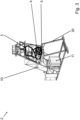
- the mixing plant 1 has a portal unit 2, which is equipped with at least one scale 3 for weighing mix components, such as cement, water, and other additives, which are conveyed from silos with closed screw conveyors to the portal unit 2.
- the portal unit 2 has a mixer 4 arranged below the scales 3 for mixing the components of the mix.
- This mixer 4 can be designed as a twin-shaft mixer, as shown in Figure 1 is indicated.
- the portal device 2 has a feeding device 10 in the form of a feeder elevator.
- This feeder elevator 10 is usually fed via row silos for the aggregates.
- the feeder elevator 10 is usually driven by a feeder drive 21, which is arranged on the portal unit 2 above the at least one scale 3.
- silos are set up near the portal unit 2. These silos are connected via screw conveyors, which convey the cement contained in the silos into the scales 3.
- the portal unit 2 also has a Control container 11, from which the mixing plant 1 is controlled.
- the gantry unit 2 is enclosed by a housing 6, which encloses the gantry unit 2 in the area of the scales 3 and the mixer 4.
- the main components of the gantry unit are easily accessible for repairs or maintenance work via the walkways 12 formed on the levels of the housing 6. Thanks to the support 20, the gantry unit 2 can be approached by truck mixers from a total of three sides.
- the portal unit 2 shown individually can be mounted and dismounted via the housing 6, which can be individually Figure 4 shown.
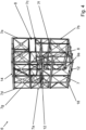
- the housing 6 consists of individually transportable modules 7, 7a, 7b, 7c, 7d, 7e, 7f, 7g, which can be combined to form the housing 6.
- the modules 7, 7a, 7b, 7c, 7d, 7e, 7f, 7g can be detachably coupled to the portal unit 2.
- the housing 6 can thus be quickly and easily assembled and disassembled from the portal unit 2 on the construction site.
- the housing 6 can be assembled and disassembled quickly and easily from the portal unit of the mobile mixing plant 1 against the weather, and the components of the portal unit 2, such as the scales 3 and the mixer 4, can be easily accessed for maintenance and repair by persons working on the portal unit 2.
- Modules 7, 7a, 7b, 7c, 7d, 7e, 7f, 7g of enclosure 6 are self-supporting.
- modules 7, 7a, 7b, 7c, 7d, 7e, 7f, 7g can be fitted with cladding 13, which forms the outer walls of enclosure 6 when mounted on portal unit 2.
- Modules 7, 7a, 7b, 7c, 7d, 7e, 7f, 7g can be covered with various surfaces 13, such as ISO panels, plastic tarpaulin, wood paneling, or similar.
- the walkways 12 from the stage levels of the enclosure 6 and also the access routes, such as ladders and/or stairs, to other levels can already be integrated into the modules 7, 7a, 7b, 7c, 7d, 7e, 7f, 7g.
- cladding 13 By paneling, it is also possible to use a railing with a handrail as a fall protection device in order to use the system partially or entirely as an open system, for example, only with a roof 14. Doors and windows can be integrated into the cladding due to the self-supporting structure of the modules. 7, 7a, 7b, 7c, 7d, 7e, 7f, 7g can be used in all suitable cladding areas according to customer requirements. Figure 5 it is indicated that the claddings 13 are simply attached to the self-supporting structure of the modules 7, 7a, 7b, 7c, 7d, 7e, 7f, 7g.
- the pre-assembled side parts 7, 7a, 7b, 7c are then coupled one after the other to the portal unit 2, before the side parts 7, 7a, 7b, 7c are connected to each other on the portal unit 2, first via the front connecting part 7f and then via the rear connecting part 7g.
- the pre-assembled roof part 7d, 7e is then attached to complete the enclosure 6 of the portal unit 2. Disassembly of the enclosure 6 from the portal unit 2 is simply carried out in reverse order. The division of the enclosure 6 shown here enables quick and easy assembly and disassembly on the portal unit 2.
- the modules 7, 7a, 7b, 7c, 7d, 7e, 7f, 7g have corresponding assembly devices 8, which enable a simple connection of the modules 7, 7a, 7b, 7c, 7d, 7e, 7f, 7g to one another and a quick separation of the modules 7, 7a, 7b, 7c, 7d, 7e, 7f, 7g from one another.
- Such an assembly device 8 is in Figure 7 shown. It connects to the Figure 4 marked point, the right side part 7b, 7c with the roof part 7e.
- the mounting device 8 is designed as a tenon-wedge connection and secured with a spring pin 15.
- a first, upper coupling device 9 can be seen, which is formed by a lockable hook 9.
- a second, lower coupling device 9a, arranged below the first coupling device 9, is additionally provided.
- the second coupling device is designed as a retaining bolt 9b.
- the module 7, 7a, 7b, 7c can be easily hooked onto the gantry unit 2 via the first coupling device 9 when coupling the mobile crane.
- the coupling device 9 has a corresponding hook receptacle on the gantry unit 2, into which the hook 9 can be hooked.
- the second coupling device 9a supports this coupling process, since the dovetail guide 9b on the gantry unit 2 simplifies the exact positioning of the modules 7, 7a, 7b, 7c on the gantry unit 2, which makes it easier to hook the hook 9 into the corresponding hook receptacle. This allows the modules 7, 7a, 7b, 7c of the enclosure 6 to be easily coupled to the portal unit 2 using a mobile crane.
- the Figures 15 and 16 illustrate the assembly step of coupling the roof 7d, 7e with the portal unit 2 and the remaining enclosure 6.
- the pre-assembled roof 14 is simply placed and bolted onto the portal unit 2 and the modules 7, 7a, 7b, 7c, 7f, 7g suspended from the portal unit 2 using a mobile crane.
- the construction of the enclosure 6 is designed such that the cement screws required for the mixing plant function can be guided through the cladding 13 of the enclosure 6 from one side or from up to three sides.
Landscapes
- Chemical & Material Sciences (AREA)
- Dispersion Chemistry (AREA)
- Preparation Of Clay, And Manufacture Of Mixtures Containing Clay Or Cement (AREA)
- Mixers With Rotating Receptacles And Mixers With Vibration Mechanisms (AREA)
Description
- Die Erfindung betrifft eine, insbesondere mobile oder auch stationäre, Mischanlage mit einer Portaleinheit, wobei die Portaleinheit mindestens eine Waage zum Abwiegen von Mischgutbestandteilen, einen Mischer zum Vermischen der Bestandteile des Mischgutes und eine Abgabevorrichtung zur Abgabe des gemischten Mischgutes umfasst, und einer Einhausung, wobei die Portaleinheit der einer montierbaren und demontierbaren Einhausung umbaubar ist, wobei die Einhausung aus jeweils transportfähigen Modulen zusammensetzbar ist.
- Eine solche Mischanlage ist in
CN 104 972 565 A offenbart. - Die
DE 10 2017 005 411 A1 offenbart eine Vorrichtung zur Herstellung von Asphalt mit mehreren einzelnen, zusammenkoppelbaren Modulen in denen Einrichtungen zur Bearbeitung oder Produktion des Asphalts, insbesondere eines Mischguts und eines Bindemittels, anordbar sind, wobei jedes Modul einen identischen Grundrahmen aufweist, der durch eine begrenzte Anzahl von möglichen, für die Funktionalität der in dem Grundrahmen anzuordnenden Einrichtung wesentlichen Ausbauelemente und Anbauelemente konfigurierbar ist. - Üblicherweise fahren Fahrmischern zur Aufnahme von Beton stationäre Mischanlagen an, die dann den in den Mischanlagen hergestellten Beton in die Fahrmischer füllen. Der in die Fahrmischer gefüllte Beton wird dann zur Baustelle transportiert. Ein solcher Transport ist jedoch unwirtschaftlich, wenn zur Herstellung großer Bauwerke, wie beispielsweise von Flughäfen, Staudämmen, Brücken oder Tunneln, große Mengen von Beton benötigt werden, der dann über große Strecken angefahren werden muss, da sich keine Mischanlage in der Nähe befindet. Zur Versorgung von Großbaustellen mit Beton ist es daher üblich, eine Betonmischanlage in unmittelbarer Nähe zu verwenden. Da derartige Mischanlagen nur bis zur Fertigstellung des Bauwerks benötigt werden, verwendet man in diesen Fällen mobile Mischanlagen.
- Es ist bekannt, solche Mischanlagen mit einer Einhausung zu versehen, welche die Portaleinheit gegen Witterung schützt und um die Komponenten, wie die Waagen und den Mischer, leicht zugänglich für Wartung und Reparaturen zu machen. Die Einhausungen verfügen daher üblicherweise über Außenwände und Laufstege, die aufwendig an der Portaleinheit befestigt werden müssen.
- Insbesondere um eine mobile Mischanlage schnell und einfach aus für den Straßentransport geeigneten Transporteinheiten zu errichten und auch wieder in solche Transporteinheiten zu zerlegen, schlägt die
DE 297 11 500 U1 vor, die mobile Mischanlage mit gelenkig an der Portaleinheit verbunden Pfosten zu versehen, die beim Aufbau aus einer Transportstellung in eine Aufbaustellung verschwenkbar sind. Eine Einhausung der Portaleinheit ist bei dieser Lösung nicht vorgesehen. Der Aufbau und Abbau einer Einhausung ist zeitaufwendig, sodass regelmäßig auf eine solche Einhausung verzichtet wird, um den Aufbau und den Abbau der mobilen Mischanlage an der Baustelle zu beschleunigen. Dies ist mit dem Nachteil verbunden, dass die Portaleinheit und an der Portaleinheit arbeitende Personen der Witterung schutzlos ausgeliefert sind. Dies stellt in einigen Klimazonen ein schwerwiegendes Problem dar. - Es ist daher Aufgabe der Erfindung, eine verbesserte Mischanlage anzugeben, die eine effektive, schnell montierbare und demontierbare Einhausung einer Portaleinheit bietet und somit ohne erhebliche Zeitverluste bei Auf- und Abbau einen wirksamen Schutz gegen Witterung und einen einfachen Zugang zu den Hauptkomponenten der Portaleinheit ermöglicht.
- Gelöst wird diese Aufgabe durch eine Mischanlage mit den Merkmalen des Anspruchs 1.
- Dadurch, dass die Einhausung der Mischanlage aus jeweils transportfähigen Modulen zusammensetzbar ist, wobei die Module an die Portaleinheit lösbar koppelbar sind, wobei die Module dazu ausgebildet sind zur Kopplung mit der Portaleinheit von einem Fahrzeugkran an die aufgestellte Portaleinheit herangehoben zu werden, kann die Einhausung schnell und einfach auf der Baustelle an der Portaleinheit montiert und demontiert werden. Mit einer solchen auf- und abbaubaren Einhausung lässt sich die Portaleinheit der mobilen Mischanlage schnell und einfach gegen Witterung schützen, und die Komponenten der Portaleinheit, wie die mindestens eine Waage und der Mischer, können für an der Portaleinheit arbeitende Personen zur Wartung und zur Reparatur einfach zugänglich gemacht werden. Der Aufbau der Einhausung aus jeweils transportfähigen Modulen, die sich ohne Sonderrechte einfach transportieren lassen, ermöglichen den Transport der Mischanlage samt Einhausung, ohne dass hierfür ein Schwertransport angemeldet muss. Dies reduziert die Kosten für den Transport der Mischanlage und macht diesen auch zeitlich flexibler. Damit kann nicht nur der Aufbau und der Abbau der Mischanlage mit der Einhausung beschleunigt werden, sondern auch der Transport zwischen zwei Baustellen. Über die einfache Kopplung der Module an der Portaleinheit ist die Einhausung beim Aufbau auf der Baustelle schnell zusammensetzbar. Beim Abbau lassen sich die Module sehr einfach von der Portaleinheit lösen und anschließend einzeln zur nächsten Baustelle transportieren. Die transportfähigen Module weisen hierzu Abmessungen auf, die einen einfachen Transport im Straßenverkehr ermöglichen.
- Vorteilhafte Ausgestaltungen und Weiterbildungen der Erfindung ergeben sich aus den abhängigen Ansprüchen. Es ist darauf hinzuweisen, dass die in den Ansprüchen einzeln aufgeführten Merkmale auch in beliebiger und technologisch sinnvoller Weise miteinander kombiniert werden können und somit weitere Ausgestaltungen der Erfindung aufzeigen.
- Gemäß einer vorteilhaften Ausgestaltung der Erfindung ist vorgesehen, dass die Module selbsttragend sind. Mit der selbsttragenden Ausgestaltung der Module kann die Einhausung zerlegt sehr einfach transportiert werden, da die einzelnen Module kompakte und stabile Transporteinheiten bilden, die sich, wie auch die Portaleinheit, einfach auf einem Tieflader transportieren lassen.
- Besonders bevorzugt ist eine Ausführungsform, die vorsieht, dass die Module über Montageeinrichtungen miteinander vormontierbar sind. Über die Vormontage der Module können diese mittels der Montageeinrichtungen bereits am Boden zusammengesetzt werden. Die über die Montageeinrichtungen vormontierten Modulteile lassen sich anschließen schnell und einfach mit der Portaleinheit koppeln. Zur Kopplung der Module mit der Portaleinheit kommt ein Fahrzeugkran zum Einsatz, der die Module, vorzugsweise im vormontierten Zustand, an die aufgestellte Portaleinheit zur Kopplung heranhebt.
- Eine besonders vorteilhafte Ausführung der Erfindung bezieht sich darauf, dass die Montageeinrichtungen als Zapfen-Keilverbinder mit Federstecker ausgebildet sind. Über die Zapfen-Keilverbinder lassen sich die Module einfach und schnell vormontieren bzw. demontieren. Mit dem Federstecker erfolgt eine einfache und schnelle Sicherung der Verbindung zwischen den über die Montageeinrichtungen vormontierten Modulen.
- Eine besonders vorteilhafte Ausführung der Erfindung sieht vor, dass die Einhausung aus zwei vormontierbaren Seitenteilen, einem vormontierbaren Dachteil und einem vorderen Verbindungsteil und einem hinteren Verbindungsteil zusammensetzbar ist. Mit dieser Aufteilung der Einhausung ist ein schnelle und einfache Montage und Demontage an der Portaleinheit möglich. Die Aufteilung der vormontierten Module kann auch in anderen Trennungen ausgeführt werden. Es ist auch denkbar, Funktionskomponenten der Mischanlage in die einzelnen Module zu integrieren, wenn dies von Vorteil ist. Auch die Größe der Einhausung kann angepasst werden, von einer Gesamtverkleidung bis zur Einhausung von einzelnen Ebenen.
- Eine vorteilhafte Ausführung der Erfindung sieht vor, dass die Einhausung die Portaleinheit im Bereich der Waage und des Mischers umschließt. Die Einhausung im Bereich der Hauptkomponenten der Portaleinheit schützt diese besonders wirksam gegen Witterung und macht diese für Wartung und Reparaturen einfach zugänglich. An der Portaleinheit arbeitende Personen können über die Einhausung sicher und geschützt Wartungsarbeiten und Reparaturen durchführen.
- Besonders vorteilhaft ist eine Ausführungsform, die vorsieht, dass die Module der Einhausung über Koppeleinrichtungen an die Portaleinheit lösbar koppelbar sind. Mit den Koppeleinrichtungen können die Module sehr einfach mit der Portaleinheit verbunden oder von der Portaleinheit getrennt werden. Die Koppeleinrichtungen bieten eine sichere und stabile Verbindung zur Bildung einer Mischanlageneinheit aus Portaleinheit und Einhausung. Die Koppeleinrichtungen bieten eine mechanisch herstellbare Verbindung zwischen den Modulen und der Portaleinheit. Die mechanische Verbindung über die Koppeleinrichtungen lässt sich zur Lösung der Module von der Portaleinheit einfach aufheben.
- Mit einer Einhausung lassen sich auch bestehende Mischanlagen einfach nachrüsten. Hierzu werden vorteilhafterweise einfach die bereits und im Folgenden beschriebenen Koppeleinrichtungen nachträglich an der Portaleinheit ergänzt.
- Weitere Merkmale, Einzelheiten und Vorteile der Erfindung ergeben sich aufgrund der nachfolgenden Beschreibung sowie anhand der Zeichnungen, die Ausführungsbeispiele der Erfindung zeigen. Einander entsprechende Gegenstände oder Elemente sind in allen Figuren mit den gleichen Bezugszeichen versehen. Es zeigen:
- Figur 1 u. 2:
- eine erfindungsgemäße Mischanlage mit Einhausung,
- Figur 3:
- die Portaleinheit,
- Figur 4:
- eine Einhausung,
- Figur 5:
- ein Modul mit Verkleidung,
- Figur 6:
- Explosionszeichnung
- Figur 7 u. 8:
- eine Montageeinrichtung,
- Figur 9:
- Einhängen von Seitenteilen,
- Figur 10:
- die Portaleinheit mit Seitenteilen,
- Figur 11:
- die Portaleinheit mit Schwalbenschwanzführungen,
- Figur 12:
- ein Modul mit Haltebolzen in Schwalbenschwanzführungen,
- Figur 13:
- ein Modul mit Haken,
- Figur 14:
- eine Detailansicht des Hakens,
- Figur 15:
- das Aufsetzen eines Dachteils und
- Figur 16:
- die Portaleinheit mit Dachteil.
- In der
Figur 1 und derFigur 2 mit dem Bezugszeichen 1 bezeichnet ist eine erfindungsgemäße Mischanlage dargestellt. Die Mischanlage 1 verfügt über eine Portaleinheit 2, welche mit mindestens einer Waage 3 zum Abwiegen von Mischgutbestandteilen, wie Zement, Wasser und anderen Zusatzmitteln, ausgestattet ist, die von Silos mit geschlossenen Förderschnecken zur Portaleinheit 2 gefördert werden. Außerdem verfügt die Portaleinheit 2 über einen unter den Waagen 3 angeordneten Mischer 4 zum Vermischen der Bestandteile des Mischgutes. Dieser Mischer 4 kann als Doppelwellenmischer ausgebildet sein, wie dies inFigur 1 angedeutet ist. Unter dem Mischer 4 befindet sich an der Portaleinheit 2 eine Abgabevorrichtung 5 in Form eines Abgabetrichters zur Abgabe des gemischten Mischgutes an einen an die Portaleinheit herangefahrenen Fahrmischer. Zur Beschickung der Waagen 3 weist die Portalvorrichtung 2 eine Zuführeinrichtung 10 in Form eines Beschickeraufzugs auf. Dieser Beschickeraufzug 10 wird üblicherweise über Reihensilos für die Zugschlagstoffe gespeist. Der Beschickeraufzug 10 wird üblicherweise von einem Beschickerantrieb 21 angetrieben, der auf der Portaleinheit 2 oberhalb der mindestens einen Waage 3 angeordnet ist. Für die Bindemittel werden in der Nähe der Portaleinheit 2 Silos aufgestellt, die über Schneckenförderer angebunden sind, welche den in den Silos enthaltenen Zement in die Waagen 3 fördern. Die Portaleinheit 2 verfügt zudem über einen Steuerungscontainer 11, von wo aus die Mischanlage 1 gesteuert wird. Die Portaleinheit 2 ist von einer Einhausung 6 umbaut, welche die Portaleinheit 2 im Bereich der Waagen 3 und im Bereich des Mischers 4 umschließt. Über die auf den Ebenen der Einhausung 6 gebildeten Laufstege 12 sind so die Hauptkomponenten der Portaleinheit einfach zugänglich für Reparaturen oder Wartungsarbeiten. Die Portaleinheit 2 lässt sich, dank der Abstützung 20, von den Fahrmischern an insgesamt drei Seiten anfahren. - Die in
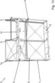
Figur 3 einzeln dargestellte Portaleinheit 2 kann über die montierbare und demontierbare Einhausung 6, welche einzeln inFigur 4 gezeigt ist, umbaut werden. Hierzu besteht die Einhausung 6 aus jeweils einzeln transportfähigen Modulen 7, 7a, 7b, 7c, 7d, 7e, 7f, 7g, welche zur Einhausung 6 zusammensetzbar sind. Die Module 7, 7a, 7b, 7c, 7d, 7e, 7f, 7g sind an die Portaleinheit 2 lösbar koppelbar. Die Einhausung 6 kann so schnell und einfach auf der Baustelle an der Portaleinheit 2 montiert und demontiert werden. Durch die auf- und abbaubare Einhausung 6 lässt sich die Portaleinheit der mobilen Mischanlage 1 schnell und einfach gegen Witterung schützen, und die Komponenten der Portaleinheit 2, wie die Waagen 3 und der Mischer 4, können für an der Portaleinheit 2 arbeitende Personen zur Wartung und zur Reparatur einfach zugänglich gemacht werden. - Die Module 7, 7a, 7b, 7c, 7d, 7e, 7f, 7g der Einhausung 6 sind selbsttragend ausgebildet. Zum Schutz gegen Witterung können die Module 7, 7a, 7b, 7c, 7d, 7e, 7f, 7g mit Verkleidungen 13 versehen werden, welche bei Montage der Einhausung 6 an der Portaleinheit 2 Außenwände der Einhausung 6 bilden. Die Module 7, 7a, 7b, 7c, 7d, 7e, 7f, 7g können zur Verkleidung wahlweise mit verschiedenen Oberflächen 13 belegt werden, wie ISO-Panele, Kunststoffplane, Holzverkleidung, oder ähnliches. Weiterhin können die Laufstege 12 von Bühnenebenen der Einhausung 6 und auch die Aufstiege, beispielsweise Leitern und/oder Treppen, in andere Ebenen bereits in die Module 7, 7a, 7b, 7c, 7d, 7e, 7f, 7g integriert sein. Anstatt der Verkleidung 13 durch Panelierung besteht weiterhin die Möglichkeit, ein Geländer mit Handlauf als Absturzsicherung zu verwenden, um die Anlage teilweise oder ganz als offene Anlage, beispielsweise nur mit Dach 14 zu verwenden. Türen und Fenster können in die Verkleidung bedingt durch die selbsttragende Struktur der Module 7, 7a, 7b, 7c, 7d, 7e, 7f, 7g in alle geeigneten Verkleidungsbereiche nach Kundenwunsch eingesetzt werden. In
Figur 5 ist angedeutet, dass die Verkleidungen 13 einfach an der selbstragenden Struktur der Module 7, 7a, 7b, 7c, 7d, 7e, 7f, 7g angebracht werden. - Die
Figur 6 zeigt eine Explosionszeichnung der Mischanlage 1 zur Verdeutlichung der Montage der modulartig aufgebauten Einhausung 6 an der Portaleinheit 2. Die Einhausung 6 besteht aus zwei vormontierbaren Seitenteilen 7, 7a, 7b, 7c, einem vormontierbaren Dachteil 7d, 7e und einem vorderen Verbindungsteil 7f und einem hinteren Verbindungsteil 7g, welche zur Bildung der Einhausung 6 modulartig zusammengesetzt werden. Zur Montage der Einhausung 6 an der Portaleinheit 2 werden zunächst am Boden die aus zwei Modulen 7, 7a und 7b, 7c gebildeten Seitenteile vormontiert. Auch das aus zwei Modulen 7d, und 7e gebildete Dachteil der Einhausung 6 kann am Boden vormontiert werden. Anschließend werden die vormontierten Seitenteile 7, 7a, 7b, 7c nacheinander an die Portaleinheit 2 gekoppelt, bevor die Seitenteile 7, 7a, 7b, 7c zunächst über das vordere Verbindungsteil 7f und dann über das hintere Verbindungsteil 7g an der Portaleinheit 2 miteinander verbunden werden. Im Anschluss wird das vormontierte Dachteil 7d, 7e aufgesetzt, um die Einhausung 6 der Portaleinheit 2 abzuschließen. Die Demontage der Einhausung 6 von der Portaleinheit 2 erfolgt einfach in umgekehrter Reihenfolge. Mit der hier gezeigten Aufteilung der Einhausung 6 ist eine schnelle und einfache Montage und Demontage an der Portaleinheit 2 möglich. - Zur Vormontage und zur Demontage verfügen die Module 7, 7a, 7b, 7c, 7d, 7e, 7f, 7g über korrespondierende Montageeinrichtungen 8, die eine einfache Verbindung der Module 7, 7a, 7b, 7c, 7d, 7e, 7f, 7g miteinander und eine schnelle Trennung der Module 7, 7a, 7b, 7c, 7d, 7e, 7f, 7g voneinander ermöglichen. Eine solche Montageeinrichtung 8 ist in
Figur 7 gezeigt. Sie verbindet an der inFigur 4 gekennzeichneten Stelle das rechte Seitenteil 7b, 7c mit dem Dachteil 7e. Die Montageeinrichtung 8 ist als Zapfen-Keilverbindung ausgebildet und mit Federstecker 15 gesichert. - In
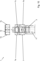
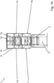
Figur 8 ist die Montageeinrichtung 8 getrennt dargestellt. Hier ist zu erkennen, dass bei Verbindung der Module 7, 7a, 7b, 7c, 7d, 7e, 7f, 7g der Zapfen 16 in dem Keil 17 aufgenommen wird. Ein Herausrutschen des Keils 17 aus dem Zapfen 16 wird durch den Federstecker 15 verhindert. Diese Verbindung über die Montageeinrichtungen 8 lässt sich zur Vormontage der Module 7, 7a, 7b, 7c, 7d, 7e, 7f, 7g einfach ohne Werkzeug herstellen und zur Demontage der Module 7, 7a, 7b, 7c, 7d, 7e, 7f, 7g ebenso einfach wieder trennen. - Die
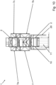
Figuren 9 und10 verdeutlichen den Vorgang der Kopplung der Seitenteile 7, 7a, 7b, 7c an der Portaleinheit 2. Zur Kopplung der Seitenteile 7, 7a, 7b, 7c werden diese einfach mit einem Autokran an der Portaleinheit 2 seitlich eingehängt, wie dies inFigur 10 zu sehen ist. - Die
Figur 11 zeigt an der Portaleinheit 2 angeordnete Schwalbenschwanzführungen, die als Koppeleinrichtungen 9b zwischen den Modulen 7, 7a, 7b, 7c, 7d, 7e, 7f, 7g und der Portaleinheit 2 dienen. Über diese Koppeleinrichtungen 9b sind die Module 7, 7a, 7b, 7c, 7d, 7e, 7f, 7g der Einhausung 6 mit der Portaleinheit 2 koppelbar und lösbar verbunden. Über die Schwalbenschwanzführung 9b wird eine exakte Positionierung der Module 7, 7a, 7b, 7c, 7d, 7e, 7f, 7g bei der Kopplung an der Portaleinheit 2 vereinfacht. Die erfindungsgemäße modulartige Einhausung 6 kann auch an bestehenden Portaleinheiten 2 nachgerüstet werden, hierzu werden vorteilhafterweise einfach die Koppeleinrichtungen 9b nachträglich ergänzt. - In der
Figur 12 sind an dem Seitenteil 7, 7a, 7b, 7c angeordnete Haltebolzen 9a zu erkennen, welche in die korrespondierenden Schwalbenschwanzführungen 9b der Koppeleinrichtungen eingreifen. Um diesen Eingriff deutlich erkennbar zu machen, sind inFigur 12 nur die Schwalbenschwanzführungen 9b gemäßFigur 11 gezeigt, ohne die restliche Portaleinheit 2. Die Haltebolzen 9a zum Einhängen in die Schwalbenschwanzführungen 9b befinden sich innerhalb des Bodentragrahmens des unteren Seitenmoduls 7, 7b. - Die
Figur 13 zeigt an dem Seitenteil 7, 7a, 7b, 7c angeordnete Haken 9, die als Koppeleinrichtungen dienen. Über diese Haken 9 wird das modulartige Seitenteil 7, 7a, 7b, 7c an der Portaleinheit 2 eingehängt. - In
Figur 14 ist eine Detailansicht auf eine Koppeleinrichtung 9 gemäßFigur 13 zu sehen. In dieser Darstellung ist zu erkennen, dass der Haken 9, beziehungsweise das Modul 7a, über einen Riegel 19 zusammen mit einem Zapfen 16 und einem Federstecker 15 mit der Portaleinheit 2 verriegelbar ist, um eine sichere Verbindung zwischen eingehängtem Modul 7, 7a, 7b, 7c und der Portaleinheit 2 herzustellen. - Im Zusammenhang mit den Koppeleinrichtungen 9, 9a wird noch einmal auf die
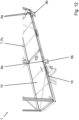
Figur 9 Bezug genommen. Hier ist eine erste, obere Koppeleinrichtung 9 zu sehen, die durch einen verriegelbaren Haken 9 gebildet ist. Eine zweite, unterhalb der ersten Koppeleinrichtung 9 angeordnete, untere Koppeleinrichtung 9a ist zusätzlich vorgesehen. Die zweite Koppeleinrichtung ist als ein Haltebolzen 9b ausgebildet. Über die erste Koppeleinrichtung 9 kann das Modul 7, 7a, 7b, 7c bei der Kopplung von dem Autokran einfach an der Portaleinheit 2 eingehängt werden. Dazu weist die Koppeleinrichtung 9 eine korrespondiere Hakenaufnahme an der Portaleinheit 2 auf, in welche der Haken 9 eingehängt werden kann. Die zweite Koppeleinrichtung 9a unterstützt diesen Koppelvorgang, da über die Schwalbenschwanzführung 9b an der Portaleinheit 2 eine exakte Positionierung der Module 7, 7a, 7b, 7c an der Portaleinheit 2 vereinfacht wird, was das Einhaken des Hakens 9 in die korrespondierende Hakenaufnahme erleichtert. Damit lassen sich die Module 7, 7a, 7b, 7c der Einhausung 6 einfach mit einem Fahrzeugkran an die Portaleinheit 2 ankoppeln. - Die
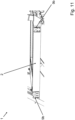
Figuren 15 und16 verdeutlichen den Montageschritt der Kopplung des Daches 7d, 7e mit der Portaleinheit 2 und der restlichen Einhausung 6. Das vormontierte Dach 14 wird zur Kopplung einfach mit einem Autokran auf die Portaleinheit 2 und die an der Portaleinheit 2 eingehängten Module 7, 7a, 7b, 7c, 7f, 7g aufgesetzt und verbolzt. Die Konstruktion der Einhausung 6 ist so ausgeführt, dass die für die Mischanlagenfunktion notwendigen Zementschnecken von einer Seite bzw. von bis zu drei Seiten durch die Verkleidung 13 der Einhausung 6 geführt werden können. -
- 1
- Mischanlage
- 2
- Portaleinheit
- 3
- Waage
- 4
- Mischer
- 5
- Abgabevorrichtung
- 6
- Einhausung
- 7
- Seitenteil links unten, 7a Seitenteil links oben, 7b Seitenteil rechts unten, 7c Seitenteil rechts oben, 7d Dachteil links, 7e Dachteil rechts, 7f Verbindungsteil vorne, 7g Verbindungsteil hinten (Module)
- 8
- Zapfen-Keilverbindung (Montageeinrichtungen)
- 9
- Haken, 9a Haltebolzen, 9b Schwalbenschwanzführung (Koppeleinrichtungen)
- 10
- Zuführeinrichtung (Beschickeraufzug)
- 11
- Steuerungscontainer
- 12
- Laufstege
- 13
- Verkleidungen
- 14
- Dach
- 15
- Federstecker
- 16
- Zapfen
- 17
- Keil
- 18
- Bodentragrahmen
- 19
- Riegel
- 20
- Abstützung
- 21
- Beschickerantrieb
Claims (7)
- Mischanlage (1) mit einer Portaleinheit (2), wobei die Portaleinheit (2) mindestens eine Waage (3) zum Abwiegen von Mischgutbestandteilen, einen Mischer (4) zum Vermischen der Bestandteile des Mischgutes und eine Abgabevorrichtung (5) zur Abgabe des gemischten Mischgutes umfasst, und einer Einhausung (6), wobei die Portaleinheit (2) von der montierbaren und demontierbaren Einhausung (6) umbaubar ist, wobei die Einhausung (6) aus jeweils transportfähigen Modulen (7, 7a, 7b, 7c, 7d, 7e, 7f, 7g) zusammensetzbar ist,
dadurch gekennzeichnet,
dass die Module (7, 7a, 7b, 7c, 7d, 7e, 7f, 7g) an die Portaleinheit (2) lösbar ankoppelbar sind, wobei die Module (7, 7a, 7b, 7c, 7d, 7e, 7f, 7g) dazu ausgebildet sind, zur Kopplung mit der Portaleinheit (2) von einem Fahrzeugkran an die aufgestellte Portaleinheit (2) herangehoben zu werden. - Mischanlage (1) nach Anspruch 1, dadurch gekennzeichnet, dass die Module (7, 7a, 7b, 7c, 7d, 7e, 7f, 7g) selbsttragend sind.
- Mischanlage (1) nach Anspruch 1 oder 2, dadurch gekennzeichnet, dass die Module (7, 7a, 7b, 7c, 7d, 7e, 7f, 7g) über Montageeinrichtungen (8) miteinander vormontierbar sind.
- Mischanlage (1) nach Anspruch 3, dadurch gekennzeichnet, dass die Montageeinrichtungen (8) als Zapfen-Keilverbinder mit Federstecker ausgebildet sind.
- Mischanlage (1) nach einem der Ansprüche 1 bis 4, dadurch gekennzeichnet, dass die Einhausung (6) aus zwei vormontierbaren Seitenteilen (7, 7a, 7b, 7c), einem vormontierbaren Dachteil (7d, 7e) und einem vorderen Verbindungsteil (7f) und einem hinteren Verbindungsteil (7g) zusammensetzbar ist.
- Mischanlage (1) nach einem der vorhergehenden Ansprüche, dadurch gekennzeichnet, dass die Einhausung (6) die Portaleinheit (2) im Bereich der Waage (3) und des Mischers (4) umschließt.
- Mischanlage (1) nach einem der vorhergehenden Ansprüche, dadurch gekennzeichnet, dass die Module (7, 7a, 7b, 7c, 7d, 7e, 7f, 7g) der Einhausung (6) über Koppeleinrichtungen (9) mit der Portaleinheit (2) koppelbar und lösbar sind.
Applications Claiming Priority (2)
| Application Number | Priority Date | Filing Date | Title |
|---|---|---|---|
| DE102019107328 | 2019-03-21 | ||
| DE102019107429.0A DE102019107429A1 (de) | 2019-03-21 | 2019-03-22 | Mischanlage und Einhausung für eine Mischanlage |
Publications (3)
| Publication Number | Publication Date |
|---|---|
| EP3722059A2 EP3722059A2 (de) | 2020-10-14 |
| EP3722059A3 EP3722059A3 (de) | 2020-12-23 |
| EP3722059B1 true EP3722059B1 (de) | 2025-05-07 |
Family
ID=72334297
Family Applications (1)
| Application Number | Title | Priority Date | Filing Date |
|---|---|---|---|
| EP20164660.1A Active EP3722059B1 (de) | 2019-03-21 | 2020-03-20 | Mischanlage mit einhausung |
Country Status (3)
| Country | Link |
|---|---|
| EP (1) | EP3722059B1 (de) |
| DE (1) | DE102019107429A1 (de) |
| ES (1) | ES3037255T3 (de) |
Family Cites Families (8)
| Publication number | Priority date | Publication date | Assignee | Title |
|---|---|---|---|---|
| DE4314001C2 (de) * | 1993-04-29 | 1996-05-09 | Gerald Merkel | Gerüstknoten |
| US5785421A (en) * | 1996-10-22 | 1998-07-28 | Milek; Robert C. | Mobile modular concrete batch plant |
| DE29711500U1 (de) * | 1997-07-01 | 1997-09-04 | Liebherr-Mischtechnik Gmbh, 88427 Bad Schussenried | Mobile Mischanlage |
| CN102555068A (zh) * | 2012-02-23 | 2012-07-11 | 三一重工股份有限公司 | 一种移动式混凝土搅拌站 |
| DE102012112816A1 (de) * | 2012-12-20 | 2014-06-26 | Bayer Technology Services Gmbh | Produktionseinrichtung zur Durchführung einer chemischen Reaktion und Verwendung eines Standard-Transportcontainers |
| CN104972565B (zh) * | 2015-07-22 | 2017-06-16 | 山推建友机械股份有限公司 | 提升斗上料方式混凝土搅拌站 |
| CN206733347U (zh) * | 2017-04-12 | 2017-12-12 | 徐州徐工施维英机械有限公司 | 一种集成模块化移动式混凝土搅拌站 |
| DE102017005411A1 (de) * | 2017-06-08 | 2018-12-13 | Linstal Spólka z o.o. | Vorrichtung und Verfahren zur Herstellung von Asphalt |
-
2019
- 2019-03-22 DE DE102019107429.0A patent/DE102019107429A1/de not_active Withdrawn
-
2020
- 2020-03-20 ES ES20164660T patent/ES3037255T3/es active Active
- 2020-03-20 EP EP20164660.1A patent/EP3722059B1/de active Active
Also Published As
| Publication number | Publication date |
|---|---|
| EP3722059A3 (de) | 2020-12-23 |
| EP3722059A2 (de) | 2020-10-14 |
| DE102019107429A1 (de) | 2020-09-24 |
| ES3037255T3 (en) | 2025-09-30 |
Similar Documents
| Publication | Publication Date | Title |
|---|---|---|
| EP3433449B1 (de) | Deckentisch und deckenschalung mit einem solchen deckentisch | |
| EP4209656B1 (de) | Modulare tunnelschalungsvorrichtung | |
| EP4334230B1 (de) | Topmodul und verfahren zum abschliessen eines aufzugschachts einer aufzuganlage | |
| DE69513954T2 (de) | Schuttröhre | |
| DE69721323T2 (de) | Betonherstellungsvorrichtung | |
| DE102022207634B3 (de) | Modulares Klapphaus mit ISO Container Maßen | |
| EP2199247B1 (de) | Drehverbindung | |
| DE29908395U1 (de) | Vorrichtungen für einen Turmdrehkran als Obendreher mit Klettereinrichtung | |
| WO2022233804A1 (de) | Verfahren zur installation einer aufzuganlage | |
| EP3722059A2 (de) | Mischanlage und einhausung für eine mischanlage | |
| DE4021948C2 (de) | Transportable Mischanlage für Baustellen | |
| DE2402474A1 (de) | Verfahren und befestigungsvorrichtung zur montage von aussenwandelementen | |
| DE202016003241U1 (de) | Anlage zum Mischen von Beton | |
| EP0236991B1 (de) | Anlage zum Behandeln von fliessfähigen festen Stoffen | |
| DE2812974A1 (de) | Verschalungseinheit fuer schalungen zur verwendung fuer die errichtung von bauwerken | |
| DE10127161B4 (de) | Parkeinrichtung | |
| EP0625619A1 (de) | Gerüstbühne | |
| DE102012220751A1 (de) | Verfahren für die Herstellung von Hochhausdecken nebst Schaltafel | |
| DE2123132A1 (de) | Fördereinrichtung für Gerüste, insbesondere Metallgerüste | |
| WO2019058153A1 (de) | Mobiles unterkunftssystem | |
| DE2013025C3 (de) | Verfahren und Vorrichtung zum Errichten eines aus einem Rahmenbaukörper und darin eingesetzten Raumeinheiten bestehenden Gebäudes | |
| DE3323724A1 (de) | Mischanlage, insbesondere zum herstellen von beton | |
| DE2926251C2 (de) | Betonbereitunsanlage | |
| DE202025107449U1 (de) | Hubvorrichtung für Fundamente | |
| EP4688636A1 (de) | Verfahren zur installation einer aufzuganlage |
Legal Events
| Date | Code | Title | Description |
|---|---|---|---|
| PUAI | Public reference made under article 153(3) epc to a published international application that has entered the european phase |
Free format text: ORIGINAL CODE: 0009012 |
|
| STAA | Information on the status of an ep patent application or granted ep patent |
Free format text: STATUS: THE APPLICATION HAS BEEN PUBLISHED |
|
| AK | Designated contracting states |
Kind code of ref document: A2 Designated state(s): AL AT BE BG CH CY CZ DE DK EE ES FI FR GB GR HR HU IE IS IT LI LT LU LV MC MK MT NL NO PL PT RO RS SE SI SK SM TR |
|
| AX | Request for extension of the european patent |
Extension state: BA ME |
|
| PUAL | Search report despatched |
Free format text: ORIGINAL CODE: 0009013 |
|
| AK | Designated contracting states |
Kind code of ref document: A3 Designated state(s): AL AT BE BG CH CY CZ DE DK EE ES FI FR GB GR HR HU IE IS IT LI LT LU LV MC MK MT NL NO PL PT RO RS SE SI SK SM TR |
|
| AX | Request for extension of the european patent |
Extension state: BA ME |
|
| RIC1 | Information provided on ipc code assigned before grant |
Ipc: B28C 9/02 20060101AFI20201116BHEP Ipc: B28C 9/04 20060101ALI20201116BHEP |
|
| STAA | Information on the status of an ep patent application or granted ep patent |
Free format text: STATUS: REQUEST FOR EXAMINATION WAS MADE |
|
| 17P | Request for examination filed |
Effective date: 20210622 |
|
| RBV | Designated contracting states (corrected) |
Designated state(s): AL AT BE BG CH CY CZ DE DK EE ES FI FR GB GR HR HU IE IS IT LI LT LU LV MC MK MT NL NO PL PT RO RS SE SI SK SM TR |
|
| STAA | Information on the status of an ep patent application or granted ep patent |
Free format text: STATUS: EXAMINATION IS IN PROGRESS |
|
| 17Q | First examination report despatched |
Effective date: 20220705 |
|
| GRAP | Despatch of communication of intention to grant a patent |
Free format text: ORIGINAL CODE: EPIDOSNIGR1 |
|
| STAA | Information on the status of an ep patent application or granted ep patent |
Free format text: STATUS: GRANT OF PATENT IS INTENDED |
|
| INTG | Intention to grant announced |
Effective date: 20241205 |
|
| GRAS | Grant fee paid |
Free format text: ORIGINAL CODE: EPIDOSNIGR3 |
|
| GRAA | (expected) grant |
Free format text: ORIGINAL CODE: 0009210 |
|
| STAA | Information on the status of an ep patent application or granted ep patent |
Free format text: STATUS: THE PATENT HAS BEEN GRANTED |
|
| AK | Designated contracting states |
Kind code of ref document: B1 Designated state(s): AL AT BE BG CH CY CZ DE DK EE ES FI FR GB GR HR HU IE IS IT LI LT LU LV MC MK MT NL NO PL PT RO RS SE SI SK SM TR |
|
| REG | Reference to a national code |
Ref country code: GB Ref legal event code: FG4D Free format text: NOT ENGLISH |
|
| REG | Reference to a national code |
Ref country code: CH Ref legal event code: EP |
|
| REG | Reference to a national code |
Ref country code: DE Ref legal event code: R096 Ref document number: 502020010987 Country of ref document: DE |
|
| REG | Reference to a national code |
Ref country code: IE Ref legal event code: FG4D Free format text: LANGUAGE OF EP DOCUMENT: GERMAN |
|
| REG | Reference to a national code |
Ref country code: NL Ref legal event code: MP Effective date: 20250507 |
|
| REG | Reference to a national code |
Ref country code: ES Ref legal event code: FG2A Ref document number: 3037255 Country of ref document: ES Kind code of ref document: T3 Effective date: 20250930 |
|
| PG25 | Lapsed in a contracting state [announced via postgrant information from national office to epo] |
Ref country code: PT Free format text: LAPSE BECAUSE OF FAILURE TO SUBMIT A TRANSLATION OF THE DESCRIPTION OR TO PAY THE FEE WITHIN THE PRESCRIBED TIME-LIMIT Effective date: 20250908 Ref country code: FI Free format text: LAPSE BECAUSE OF FAILURE TO SUBMIT A TRANSLATION OF THE DESCRIPTION OR TO PAY THE FEE WITHIN THE PRESCRIBED TIME-LIMIT Effective date: 20250507 |
|
| REG | Reference to a national code |
Ref country code: LT Ref legal event code: MG9D |
|
| PG25 | Lapsed in a contracting state [announced via postgrant information from national office to epo] |
Ref country code: NO Free format text: LAPSE BECAUSE OF FAILURE TO SUBMIT A TRANSLATION OF THE DESCRIPTION OR TO PAY THE FEE WITHIN THE PRESCRIBED TIME-LIMIT Effective date: 20250807 Ref country code: GR Free format text: LAPSE BECAUSE OF FAILURE TO SUBMIT A TRANSLATION OF THE DESCRIPTION OR TO PAY THE FEE WITHIN THE PRESCRIBED TIME-LIMIT Effective date: 20250808 |
|
| PG25 | Lapsed in a contracting state [announced via postgrant information from national office to epo] |
Ref country code: PL Free format text: LAPSE BECAUSE OF FAILURE TO SUBMIT A TRANSLATION OF THE DESCRIPTION OR TO PAY THE FEE WITHIN THE PRESCRIBED TIME-LIMIT Effective date: 20250507 Ref country code: NL Free format text: LAPSE BECAUSE OF FAILURE TO SUBMIT A TRANSLATION OF THE DESCRIPTION OR TO PAY THE FEE WITHIN THE PRESCRIBED TIME-LIMIT Effective date: 20250507 |
|
| PG25 | Lapsed in a contracting state [announced via postgrant information from national office to epo] |
Ref country code: BG Free format text: LAPSE BECAUSE OF FAILURE TO SUBMIT A TRANSLATION OF THE DESCRIPTION OR TO PAY THE FEE WITHIN THE PRESCRIBED TIME-LIMIT Effective date: 20250507 |
|
| PG25 | Lapsed in a contracting state [announced via postgrant information from national office to epo] |
Ref country code: HR Free format text: LAPSE BECAUSE OF FAILURE TO SUBMIT A TRANSLATION OF THE DESCRIPTION OR TO PAY THE FEE WITHIN THE PRESCRIBED TIME-LIMIT Effective date: 20250507 |
|
| PG25 | Lapsed in a contracting state [announced via postgrant information from national office to epo] |
Ref country code: RS Free format text: LAPSE BECAUSE OF FAILURE TO SUBMIT A TRANSLATION OF THE DESCRIPTION OR TO PAY THE FEE WITHIN THE PRESCRIBED TIME-LIMIT Effective date: 20250807 |
|
| PG25 | Lapsed in a contracting state [announced via postgrant information from national office to epo] |
Ref country code: IS Free format text: LAPSE BECAUSE OF FAILURE TO SUBMIT A TRANSLATION OF THE DESCRIPTION OR TO PAY THE FEE WITHIN THE PRESCRIBED TIME-LIMIT Effective date: 20250907 |
|
| PG25 | Lapsed in a contracting state [announced via postgrant information from national office to epo] |
Ref country code: LV Free format text: LAPSE BECAUSE OF FAILURE TO SUBMIT A TRANSLATION OF THE DESCRIPTION OR TO PAY THE FEE WITHIN THE PRESCRIBED TIME-LIMIT Effective date: 20250507 |
|
| PG25 | Lapsed in a contracting state [announced via postgrant information from national office to epo] |
Ref country code: SM Free format text: LAPSE BECAUSE OF FAILURE TO SUBMIT A TRANSLATION OF THE DESCRIPTION OR TO PAY THE FEE WITHIN THE PRESCRIBED TIME-LIMIT Effective date: 20250507 Ref country code: DK Free format text: LAPSE BECAUSE OF FAILURE TO SUBMIT A TRANSLATION OF THE DESCRIPTION OR TO PAY THE FEE WITHIN THE PRESCRIBED TIME-LIMIT Effective date: 20250507 |
|
| PG25 | Lapsed in a contracting state [announced via postgrant information from national office to epo] |
Ref country code: CZ Free format text: LAPSE BECAUSE OF FAILURE TO SUBMIT A TRANSLATION OF THE DESCRIPTION OR TO PAY THE FEE WITHIN THE PRESCRIBED TIME-LIMIT Effective date: 20250507 |
|
| PG25 | Lapsed in a contracting state [announced via postgrant information from national office to epo] |
Ref country code: EE Free format text: LAPSE BECAUSE OF FAILURE TO SUBMIT A TRANSLATION OF THE DESCRIPTION OR TO PAY THE FEE WITHIN THE PRESCRIBED TIME-LIMIT Effective date: 20250507 |
|
| PG25 | Lapsed in a contracting state [announced via postgrant information from national office to epo] |
Ref country code: SK Free format text: LAPSE BECAUSE OF FAILURE TO SUBMIT A TRANSLATION OF THE DESCRIPTION OR TO PAY THE FEE WITHIN THE PRESCRIBED TIME-LIMIT Effective date: 20250507 Ref country code: RO Free format text: LAPSE BECAUSE OF FAILURE TO SUBMIT A TRANSLATION OF THE DESCRIPTION OR TO PAY THE FEE WITHIN THE PRESCRIBED TIME-LIMIT Effective date: 20250507 |
|
| PG25 | Lapsed in a contracting state [announced via postgrant information from national office to epo] |
Ref country code: IT Free format text: LAPSE BECAUSE OF FAILURE TO SUBMIT A TRANSLATION OF THE DESCRIPTION OR TO PAY THE FEE WITHIN THE PRESCRIBED TIME-LIMIT Effective date: 20250507 |
|
| REG | Reference to a national code |
Ref country code: DE Ref legal event code: R097 Ref document number: 502020010987 Country of ref document: DE |
|
| PLBE | No opposition filed within time limit |
Free format text: ORIGINAL CODE: 0009261 |
|
| STAA | Information on the status of an ep patent application or granted ep patent |
Free format text: STATUS: NO OPPOSITION FILED WITHIN TIME LIMIT |
|
| REG | Reference to a national code |
Ref country code: CH Ref legal event code: L10 Free format text: ST27 STATUS EVENT CODE: U-0-0-L10-L00 (AS PROVIDED BY THE NATIONAL OFFICE) Effective date: 20260318 |
|
| PGFP | Annual fee paid to national office [announced via postgrant information from national office to epo] |
Ref country code: GB Payment date: 20260304 Year of fee payment: 7 |
|
| PGFP | Annual fee paid to national office [announced via postgrant information from national office to epo] |
Ref country code: DE Payment date: 20260320 Year of fee payment: 7 |
|
| 26N | No opposition filed |
Effective date: 20260210 |
|
| PGFP | Annual fee paid to national office [announced via postgrant information from national office to epo] |
Ref country code: FR Payment date: 20260323 Year of fee payment: 7 |
|
| PGFP | Annual fee paid to national office [announced via postgrant information from national office to epo] |
Ref country code: TR Payment date: 20260302 Year of fee payment: 7 |