EP3722016A1 - Procédé d'analyse de cause de variation de retour élastique - Google Patents
Procédé d'analyse de cause de variation de retour élastique Download PDFInfo
- Publication number
- EP3722016A1 EP3722016A1 EP18886420.1A EP18886420A EP3722016A1 EP 3722016 A1 EP3722016 A1 EP 3722016A1 EP 18886420 A EP18886420 A EP 18886420A EP 3722016 A1 EP3722016 A1 EP 3722016A1
- Authority
- EP
- European Patent Office
- Prior art keywords
- press forming
- stress
- springback
- forming part
- distribution
- Prior art date
- Legal status (The legal status is an assumption and is not a legal conclusion. Google has not performed a legal analysis and makes no representation as to the accuracy of the status listed.)
- Pending
Links
Images


Classifications
-
- G—PHYSICS
- G01—MEASURING; TESTING
- G01M—TESTING STATIC OR DYNAMIC BALANCE OF MACHINES OR STRUCTURES; TESTING OF STRUCTURES OR APPARATUS, NOT OTHERWISE PROVIDED FOR
- G01M5/00—Investigating the elasticity of structures, e.g. deflection of bridges or air-craft wings
- G01M5/0041—Investigating the elasticity of structures, e.g. deflection of bridges or air-craft wings by determining deflection or stress
-
- G—PHYSICS
- G06—COMPUTING OR CALCULATING; COUNTING
- G06F—ELECTRIC DIGITAL DATA PROCESSING
- G06F30/00—Computer-aided design [CAD]
- G06F30/20—Design optimisation, verification or simulation
-
- B—PERFORMING OPERATIONS; TRANSPORTING
- B21—MECHANICAL METAL-WORKING WITHOUT ESSENTIALLY REMOVING MATERIAL; PUNCHING METAL
- B21C—MANUFACTURE OF METAL SHEETS, WIRE, RODS, TUBES, PROFILES OR LIKE SEMI-MANUFACTURED PRODUCTS OTHERWISE THAN BY ROLLING; AUXILIARY OPERATIONS USED IN CONNECTION WITH METAL-WORKING WITHOUT ESSENTIALLY REMOVING MATERIAL
- B21C51/00—Measuring, gauging, indicating, counting, or marking devices specially adapted for use in the production or manipulation of material in accordance with subclasses B21B - B21F
-
- B—PERFORMING OPERATIONS; TRANSPORTING
- B21—MECHANICAL METAL-WORKING WITHOUT ESSENTIALLY REMOVING MATERIAL; PUNCHING METAL
- B21D—WORKING OR PROCESSING OF SHEET METAL OR METAL TUBES, RODS OR PROFILES WITHOUT ESSENTIALLY REMOVING MATERIAL; PUNCHING METAL
- B21D22/00—Shaping without cutting, by stamping, spinning, or deep-drawing
-
- G—PHYSICS
- G06—COMPUTING OR CALCULATING; COUNTING
- G06F—ELECTRIC DIGITAL DATA PROCESSING
- G06F30/00—Computer-aided design [CAD]
- G06F30/20—Design optimisation, verification or simulation
- G06F30/23—Design optimisation, verification or simulation using finite element methods [FEM] or finite difference methods [FDM]
-
- B—PERFORMING OPERATIONS; TRANSPORTING
- B21—MECHANICAL METAL-WORKING WITHOUT ESSENTIALLY REMOVING MATERIAL; PUNCHING METAL
- B21D—WORKING OR PROCESSING OF SHEET METAL OR METAL TUBES, RODS OR PROFILES WITHOUT ESSENTIALLY REMOVING MATERIAL; PUNCHING METAL
- B21D22/00—Shaping without cutting, by stamping, spinning, or deep-drawing
- B21D22/20—Deep-drawing
- B21D22/22—Deep-drawing with devices for holding the edge of the blanks
-
- G—PHYSICS
- G06—COMPUTING OR CALCULATING; COUNTING
- G06F—ELECTRIC DIGITAL DATA PROCESSING
- G06F2113/00—Details relating to the application field
- G06F2113/22—Moulding
-
- G—PHYSICS
- G06—COMPUTING OR CALCULATING; COUNTING
- G06F—ELECTRIC DIGITAL DATA PROCESSING
- G06F2113/00—Details relating to the application field
- G06F2113/24—Sheet material
-
- G—PHYSICS
- G06—COMPUTING OR CALCULATING; COUNTING
- G06F—ELECTRIC DIGITAL DATA PROCESSING
- G06F2119/00—Details relating to the type or aim of the analysis or the optimisation
- G06F2119/14—Force analysis or force optimisation, e.g. static or dynamic forces
-
- G—PHYSICS
- G06—COMPUTING OR CALCULATING; COUNTING
- G06F—ELECTRIC DIGITAL DATA PROCESSING
- G06F2119/00—Details relating to the type or aim of the analysis or the optimisation
- G06F2119/18—Manufacturability analysis or optimisation for manufacturability
-
- Y—GENERAL TAGGING OF NEW TECHNOLOGICAL DEVELOPMENTS; GENERAL TAGGING OF CROSS-SECTIONAL TECHNOLOGIES SPANNING OVER SEVERAL SECTIONS OF THE IPC; TECHNICAL SUBJECTS COVERED BY FORMER USPC CROSS-REFERENCE ART COLLECTIONS [XRACs] AND DIGESTS
- Y02—TECHNOLOGIES OR APPLICATIONS FOR MITIGATION OR ADAPTATION AGAINST CLIMATE CHANGE
- Y02P—CLIMATE CHANGE MITIGATION TECHNOLOGIES IN THE PRODUCTION OR PROCESSING OF GOODS
- Y02P90/00—Enabling technologies with a potential contribution to greenhouse gas [GHG] emissions mitigation
- Y02P90/02—Total factory control, e.g. smart factories, flexible manufacturing systems [FMS] or integrated manufacturing systems [IMS]
Definitions
- the present invention relates to a springback amount variation cause analysis method (springback variation cause analysis method) for analyzing a portion that is a cause of variation in springback amount in a press forming part due to scattering or variation in press forming conditions.
- Springback is the behavior of elastic recovery, which is generated when internal stress in a press forming part at the time of completion of sandwiching by upper and lower tools of press forming (bottom dead center) (bottom dead center stress) is released at the time of die release.
- bottom dead center stress bottom dead center stress
- Patent Literature 1 to Patent Literature 7 discloses a method for confirming a relation between change in press forming conditions as countermeasures against springback and change in stress state as the entire shape of a press forming part before and after die release.
- Patent Literature 1 to Patent Literature 7 the physical amount such as stress before generating springback is changed for a partial area of a press forming part, and the influence on the springback is evaluated, and hence a portion as a cause of the generation of springback itself can be analyzed.
- the methods do not involve the case where difference (scattering) in press forming conditions including characteristic variation in press forming metallic sheet affects variation in springback amount.
- the method disclosed in Patent Literature 8 is to confirm the effect of springback countermeasures by visually displaying a change amount of difference in stress distribution before and after springback countermeasures, and does not analyze a portion that is a cause of generation of springback, and scattering in press forming conditions is not taken into consideration. In this manner, the technology for evaluating variation in springback amount due to scattering or variation in press forming conditions and further analyzing where a cause of variation in springback amount is generated in the press forming part has not been proposed.
- the present invention has been made in view of the above-mentioned problems, and it is an object thereof to provide a springback variation cause analysis method for analyzing a portion where scattering or variation in press forming conditions becomes a cause of variation in springback amount.
- Press forming conditions in the present application are mechanical properties of a press forming metallic sheet (blank), the thickness and shape of the press forming metallic sheet, temperature of the press forming metallic sheet, sliding characteristics between the press forming metallic sheet and a tool of press forming, the relative position of the press forming metallic sheet with respect to the tool of press forming, the position and shape of a positioning device for the press forming metallic sheet, mechanical properties of press forming tool material, the shape of the surface of the tool of press forming, the internal structure of the tool of press forming, blank holder force, blank holder position, the position and shape of a device for applying blank holder force to component parts of the tool of press forming, the relative position of the component parts of the tool of press forming, the relative speed of movement of the tool of press forming, the vibration of the tool of press forming, the temperature of the tool of press forming, atmospheric temperature, atmospheric components, a pressurizing device, and electromagnetic environments.
- Scattering or variation in press forming conditions refers to a state in which press forming conditions for the purpose of obtaining the same press forming part are scattered or varied uniformly or non-uniformly in a part or whole of processing space at the time of start of press forming, or during press forming or during die release.
- a springback variation cause analysis method of analyzing a portion in a press forming part that is a cause of variation in springback amount when the variation occurs in springback amount in the press forming part due to scattering or variation in press forming conditions includes: a first press forming condition stress distribution calculation step of performing press forming analysis under first press forming conditions set in advance, and calculating a stress distribution in a press forming part at a press forming bottom dead center; a second press forming condition stress distribution calculation step of performing press forming analysis under second press forming conditions set differently from the first press forming conditions, and calculating a stress distribution in the press forming part at the press forming bottom dead center; a stress difference distribution setting step of calculating a difference between the stress distribution calculated at the second press forming condition stress distribution calculation step and the stress distribution calculated at the first press forming condition stress distribution calculation step as a stress difference distribution, and replacing and setting the stress distribution in the press forming part at the press forming bottom dead center calculated at the
- a springback variation cause analysis method of analyzing a portion in a press forming part that is a cause of variation in springback amount when the variation occurs in springback amount in a press forming part due to scattering or variation in press forming conditions includes: a first press forming part stress distribution acquisition step of press forming a first press forming part under first press forming conditions in advance, creating a first press forming part model from three-dimensional shape measurement data obtained by measuring a surface shape of the first press forming part after die release, performing mechanical analysis in a state in which the first press forming part model is sandwiched by a tool-of-press-forming model until reaching a press forming bottom dead center, and acquiring stress distribution in the first press forming part at the press forming bottom dead center; a second press forming part stress distribution acquisition step of press forming a second press forming part under second press forming conditions different from the first press forming conditions, creating a second press forming part model from three-dimensional shape measurement data obtained by measuring a surface
- the press forming conditions include: mechanical properties of a press forming metallic sheet, a thickness and a shape of the press forming metallic sheet, temperature of the press forming metallic sheet, sliding characteristics between the press forming metallic sheet and a tool of press forming, a relative position of the press forming metallic sheet with respect to the tool of press forming, a position and a shape of a positioning device for the press forming metallic sheet, mechanical properties of press forming tool material, a shape of a surface of the tool of press forming, an internal structure of the tool of press forming, blank holder force, a blank holder position, a position and a shape of a device for applying blank holder force to component parts of the tool of press forming, an initial relative position of the component parts of the tool of press forming, relative speed of movement of the tool of press forming, vibration of the tool of press forming, temperature of the tool of press forming, atmospheric temperature, atmospheric components, a pressurizing device, and electromagnetic environments
- the stress difference distribution changing step changes the value of the stress difference by any one of removal of a component of the stress difference distribution in at least one direction, constant times, addition of a constant, constant multiplication, replacement with an average value in a sheet thickness direction of a press forming metallic sheet, or replacement with a median value in the sheet thickness direction.
- a portion that is a cause of variation in springback amount in a press forming part due to scattering or variation in press forming conditions can be analyzed, and a portion in the press forming part for which countermeasures against shape stability for mass production of the press forming part are necessary can be accurately and easily analyzed.
- FIG. 3 are diagrams illustrating, in the first embodiment, an analysis result (a) of stress distribution at a press forming bottom dead center calculated by press forming analysis under first press forming conditions (material A) of material strength of a press forming metallic sheet and an analysis result (b) of displacement calculated by springback analysis based on the stress distribution.
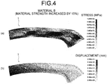
- FIG. 4 are diagrams illustrating, in the first embodiment, an analysis result (a) of stress distribution at the press forming bottom dead center calculated by press forming analysis under second press forming conditions (material B) in which the material strength of the press forming metallic sheet was increased by 15% and an analysis result (b) of displacement calculated by springback analysis based on the stress distribution.
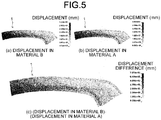
- FIG. 5 are diagrams illustrating, in the first embodiment, displacement (a) after springback analysis under the press forming conditions of the material B, displacement (b) after springback analysis under the press forming conditions of the material A, and difference (c) between the displacement under the press forming conditions of the material B and the displacement under the press forming conditions of the material A.
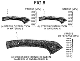
- FIG. 6 are diagrams illustrating, in the first embodiment, stress distribution (a) at the press forming bottom dead center under the press forming conditions of the material B, stress distribution (b) at the press forming bottom dead center under the press forming conditions of the material A, and difference (c) between the stress distribution in the material B at the press forming bottom dead center and the stress distribution in the material A at the press forming bottom dead center.
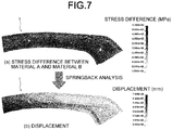
- FIG. 7 are diagrams illustrating difference (a) between the stress distribution in the material B at the press forming bottom dead center and the stress distribution in the material A at the press forming bottom dead center and displacement (b) calculated by springback analysis based on the difference in stress distribution.
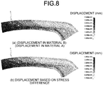
- FIG. 8 are diagrams illustrating difference (a) in displacement calculated by springback analysis under the press forming conditions of the material B and the material A and displacement (b) calculated by springback analysis based on the stress difference at the press forming bottom dead center under the press forming conditions of the material B and the material A.
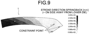
- FIG. 9 is a diagram illustrating springback analysis and an analysis result of displacement determined by the springback analysis in the first embodiment.
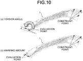
- FIG. 10 are diagrams for describing methods for calculating a torsion angle and a warping amount as springback amount in the first embodiment.
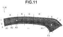
- FIG. 11 is a diagram for describing division of areas in a press forming part in the first embodiment.
- FIG. 12 are diagrams illustrating, in the first embodiment, an area (a) in which stress difference is changed and displacement (b) calculated by springback analysis by changing the stress difference in the area (No. 1).
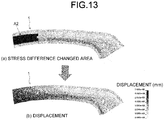
- FIG. 13 are diagrams illustrating, in the first embodiment, an area (a) in which stress difference is changed and displacement (b) calculated by springback analysis by changing the stress difference in the area (No. 2).
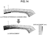
- FIG. 14 are diagrams illustrating, in the first embodiment, an area (a) in which stress difference is changed and displacement (b) calculated by springback analysis by changing the stress difference in the area (No. 3).
- FIG. 15 are diagrams illustrating, in the first embodiment, an area (a) in which stress difference is changed and displacement (b) calculated by springback analysis by changing the stress difference in the area (No. 4).
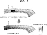
- FIG. 16 are diagrams illustrating, in the first embodiment, an area (a) in which stress difference is changed and displacement (b) calculated by springback analysis by changing the stress difference in the area (No. 5).
- FIG. 17 are diagrams illustrating, in the first embodiment, an area (a) in which stress difference is changed and displacement (b) calculated by springback analysis by changing the stress difference in the area (No. 6).
- FIG. 18 are diagrams illustrating, in the first embodiment, an area (a) in which stress difference is changed and displacement (b) calculated by springback analysis by changing the stress difference in the area (No. 7).
- FIG. 19 are diagrams illustrating, in the first embodiment, an area (a) in which stress difference is changed and displacement (b) calculated by springback analysis by changing the stress difference in the area (No. 8).
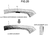
- FIG. 20 are diagrams illustrating, in the first embodiment, an area (a) in which stress difference is changed and displacement (b) calculated by springback analysis by changing the stress difference in the area (No. 9).
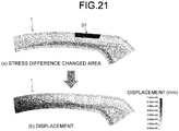
- FIG. 21 are diagrams illustrating, in the first embodiment, an area (a) in which stress difference is changed and displacement (b) calculated by springback analysis by changing the stress difference in the area (No. 10).
- FIG. 22 are diagrams illustrating, in the first embodiment, an area (a) in which stress difference is changed and displacement (b) calculated by springback analysis by changing the stress difference in the area (No. 11).
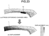
- FIG. 23 are diagrams illustrating, in the first embodiment, an area (a) in which stress difference is changed and displacement (b) calculated by springback analysis by changing the stress difference in the area (No. 12).
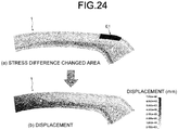
- FIG. 24 are diagrams illustrating, in the first embodiment, an area (a) in which stress difference is changed and displacement (b) calculated by springback analysis by changing the stress difference in the area (No. 13).
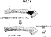
- FIG. 25 are diagrams illustrating, in the first embodiment, an area (a) in which stress difference is changed and displacement (b) calculated by springback analysis by changing the stress difference in the area (No. 14).
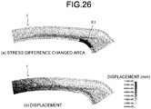
- FIG. 26 are diagrams illustrating, in the first embodiment, an area (a) in which stress difference is changed and displacement (b) calculated by springback analysis by changing the stress difference in the area (No. 15).
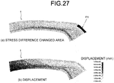
- FIG. 27 are diagrams illustrating, in the first embodiment, an area (a) in which stress difference is changed and displacement (b) calculated by springback analysis by changing the stress difference in the area (No. 16).
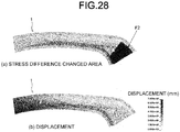
- FIG. 28 are diagrams illustrating, in the first embodiment, an area (a) in which stress difference is changed and displacement (b) calculated by springback analysis by changing the stress difference in the area (No. 17).
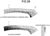
- FIG. 29 are diagrams illustrating, in the first embodiment, an area (a) in which stress difference is changed and displacement (b) calculated by springback analysis by changing the stress difference in the area (No. 18).
- FIG. 30 is a graph illustrating a relation between areas in the press forming part in which stress difference distribution was removed and variation in torsion angle caused by springback when the stress difference was removed in the first embodiment.
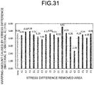
- FIG. 31 is a graph illustrating a relation between the areas in which the stress difference distribution was removed and variation in warping amount caused by springback when the stress difference was removed in the first embodiment.
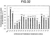
- FIG. 32 is a graph illustrating, as an example of a result of analyzing a portion that is a cause of generation of springback by conventional technology, a relation between areas in which stress distribution at the press forming bottom dead center was changed and torsion angles caused by springback when the stress distribution was changed.
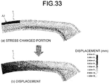
- FIG. 33 are diagrams illustrating an area (a) in which the stress distribution at the press forming bottom dead center under the press forming conditions of the material B is replaced with the stress distribution at the press forming bottom dead center under the press forming conditions of the material A and displacement (b) when springback analysis was performed by replacing the stress distribution (No. 1).
- FIG. 34 are diagrams illustrating an area (a) in which the stress distribution at the press forming bottom dead center under the press forming conditions of the material B is replaced with the stress distribution at the press forming bottom dead center under the press forming conditions of the material A and displacement (b) when springback analysis was performed by replacing the stress distribution (No. 2).
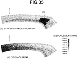
- FIG. 35 are diagrams illustrating an area (a) in which the stress distribution at the press forming bottom dead center under the press forming conditions of the material B is replaced with the stress distribution at the press forming bottom dead center under the press forming conditions of the material A and displacement (b) when springback analysis was performed by replacing the stress distribution (No. 3).
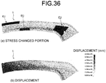
- FIG. 36 are diagrams illustrating an area (a) in which the stress distribution at the press forming bottom dead center under the press forming conditions of the material B is replaced with the stress distribution at the press forming bottom dead center under the press forming conditions of the material A and displacement (b) when springback analysis was performed by replacing the stress distribution (No. 4).
- FIG. 37 is a graph illustrating a relation between areas in which the stress distribution at the press forming bottom dead center under the press forming conditions of the material B is replaced with stress distribution at the press forming bottom dead center under the press forming conditions of the material A and torsion angles caused by springback when the stress distribution was changed.
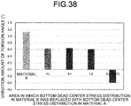
- FIG. 38 is a graph illustrating a relation between areas in which the stress distribution at the press forming bottom dead center under the press forming conditions of the material B is replaced with the stress distribution at the press forming bottom dead center under the press forming conditions of the material A and variation in torsion angle caused by springback when the stress distribution was changed.
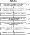
- FIG. 39 is a flowchart illustrating the flow of processing in a springback variation cause analysis method according to the second embodiment.
- FIG. 40 is a diagram for describing the processing in the springback variation cause analysis method according to the second embodiment.
- FIG. 41 are diagrams illustrating, in an example, stress distribution (a) at the press forming bottom dead center calculated by press forming analysis under press forming conditions (tool of press forming B) in which the shape of a tool of press forming was different and displacement (b) calculated by springback analysis based on the stress distribution.
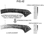
- FIG. 42 are diagrams illustrating, in the example, difference (a) in stress distribution at the press forming bottom dead center under press forming conditions of a tool of press forming A and the tool of press forming B and displacement (b) calculated by springback analysis based on the difference in stress distribution.
- FIG. 43 are diagrams illustrating, in the example, displacement calculated by springback analysis under two press forming conditions (tool of press forming B and tool of press forming A) in which the shapes of the tools of press forming were different, and displacement difference ((a): displacement after springback with tool of press forming B, (b) displacement after springback with tool of press forming A, and (c) displacement difference after springback between tool of press forming B and tool of press forming A).
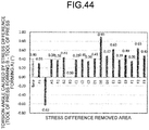
- FIG. 44 is a graph illustrating, in the example, a relation between areas in which stress difference distribution was removed and variation in torsion angle caused by springback when the stress difference was removed in the case where there was scattering among the shapes of tools of press forming.
- FIG. 45 is a graph illustrating, in the example, a relation between areas in which stress difference distribution was removed and variation in warping amount caused by springback when the stress difference was removed in the case where there was scattering in the shapes of tools of press forming.
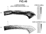
- FIG. 46 are diagrams illustrating, in the example, stress distribution (a) at the press forming bottom dead center calculated by press forming analysis under press forming conditions (lubrication B) in which the amount of lubricant was different and displacement (b) calculated by springback analysis based on the stress distribution.
- FIG. 47 are diagrams illustrating, in the example, difference (a) in stress distribution at the press forming bottom dead center under press forming conditions of lubrication A and the lubrication B and displacement (b) calculated by springback analysis based on the difference in stress distribution.
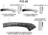
- FIG. 48 are diagrams illustrating, in the example, displacement calculated by springback analysis under two press forming conditions (lubrication B and lubrication A) in which the amounts of lubricant were different, and displacement difference ((a): displacement after springback with lubrication B, (b) displacement after springback with lubrication A, and (c) displacement difference after springback between lubrication B and lubrication A) .
- FIG. 49 is a graph illustrating, in the example, a relation between areas in which stress difference distribution was removed and variation in torsion angle caused by springback when the stress difference was removed in the case where there was scattering in lubricating conditions.
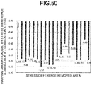
- FIG. 50 is a graph illustrating, in the example, a relation between the areas in which the stress difference distribution was removed and variation in warping amount caused by springback when the stress difference was removed in the case where there was scattering in lubricating conditions.
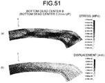
- FIG. 51 are diagrams illustrating, in the example, stress distribution (a) at the press forming bottom dead center calculated by press forming analysis under press forming conditions (a bottom dead center B) in which the position of the press forming bottom dead center was different and displacement (b) calculated by springback analysis based on the stress distribution.
- FIG. 52 are diagrams illustrating, in the example, displacement calculated by springback analysis under two press forming conditions (the bottom dead center B and a bottom dead center A) in which the press forming bottom dead center positions were different, and displacement difference ((a): displacement after springback at the bottom dead center B, (b) displacement after springback at the bottom dead center A, and (c) displacement difference after springback between the bottom dead center B and the bottom dead center A).
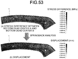
- FIG. 53 are diagrams illustrating, in the example, difference (a) in stress distribution at the press forming bottom dead center under the press forming conditions of the bottom dead center A and the bottom dead center B and displacement (b) calculated by springback analysis based on the difference in stress distribution.
- FIG. 54 is a graph illustrating, in the example, a relation between areas in which stress difference distribution was removed and variation in torsion angle caused by springback when the stress difference was removed in the case where there was scattering in position of the press forming bottom dead center.
- FIG. 55 is a graph illustrating, in the example, a relation between the areas in which the stress difference distribution was removed and variation in warping amount caused by springback when the stress difference was removed in the case where there was scattering in position of the press forming bottom dead center.
- variation may occur in springback amount after die release of the press forming part 1 due to scattering or variation in press forming conditions, such as variation in properties of press forming metallic sheets.
- a portion that is a cause of the variation in springback amount due to scattering or variation in press forming conditions may be different from a portion that is a cause of the generation of springback itself.
- the inventor of the present invention diligently made a study for solving such a problem.
- the inventor of the present invention thought that a cause of variation in springback in press forming parts press formed under two different press forming conditions (first press forming conditions and second press forming conditions) as scattering or variation in press forming conditions is due to difference between stress distribution at the press forming bottom dead center in a press forming part 1 press formed under the first press forming conditions and stress distribution at the press forming bottom dead center in a press forming part 1 press formed under the second press forming conditions.
- first press forming conditions are referred to as “material A” and second press forming conditions are referred to as "material B" in which material strengths of press forming metallic sheets have scattering as illustrated in Table 1
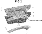
- press forming analysis on a press forming part 1 having a hat cross-sectional shape illustrated in FIG. 2 was performed to calculate stress distribution at the press forming bottom dead center, and further, displacement caused by springback was calculated by springback analysis using the stress distribution to determine difference in displacement under the two press forming conditions.
- “material B” illustrated in Table 1 has the material strength of the press forming metallic sheet increased by 15% as compared with "material A”.
- FIG. 3 and FIG. 4 illustrate analysis results of stress distribution at the press forming bottom dead center calculated under the press forming conditions of the material A and the material B, and displacement caused by springback after die release of the press forming parts press formed under the press forming conditions.
- FIG. 5 illustrate difference in displacement caused by springback under the two press forming conditions.
- Table 1 Press forming conditions Thickness t [mm] Material strength YP [MPa] TS [MPa] Material A 1.4 687 1011 Material B 1.4 790 1163
- stress difference distribution difference between stress distribution at the press forming bottom dead center under the first press forming conditions (material A) and stress distribution at the press forming bottom dead center under the second press forming conditions (material B) determined by the above-mentioned press forming analysis (hereinafter referred to as "stress difference distribution") was calculated, springback analysis was performed by replacing the stress distribution at the press forming bottom dead center under the first press forming conditions with the calculated stress difference distribution, and displacement caused by springback based on the stress difference distribution was determined.
- FIG. 6 illustrate stress difference distribution at the press forming bottom dead center under the two press forming conditions
- FIG. 7 illustrate displacement determined by springback analysis based on the stress difference distribution.
- the inventor of the present invention obtained the finding that the stress difference distribution as difference in stress distribution at the press forming bottom dead center under the two press forming conditions is a cause of variation in springback amount due to scattering in press forming conditions, and the stress difference distribution at the press forming bottom dead center under the two press forming conditions can be regarded as driving power for transition from the state after springback under the first press forming conditions to the shape after springback under the second press forming conditions.
- Patent Literature 5 indicates that the stress distribution at the press forming bottom dead center under the first press forming conditions and the stress distribution at the press forming bottom dead center under the second press forming conditions are compared.
- arithmetic processing is performed on at least one piece of data on a physical property value or a physical amount under the first press forming conditions in the area in which the difference is larger than the predetermined value, but the difference in physical amount (stress distribution at the press forming bottom dead center) is not calculated for the entire press forming part.
- Patent Literature 6 and Patent Literature 8 Methods for determining the difference in stress distribution in a press forming part at the press forming bottom dead center are disclosed in Patent Literature 6 and Patent Literature 8.
- the difference in stress distribution before and after springback under one kind of press forming conditions, and springback effective stress is calculated.
- the method disclosed in Patent Literature 8 is to evaluate a change amount before and after countermeasures against springback with respect to difference in stress distribution before and after springback.
- the change amount of difference in stress distribution corresponds to springback countermeasures, that is, driving power for the change in springback.
- Patent Literature 6 and Patent Literature 8 have not reached an important viewpoint that difference in stress distribution at the press forming bottom dead center under two different press forming conditions due to scattering or variation in press forming conditions is a cause of variation in springback amount due to scattering in press forming conditions.
- a springback variation cause analysis method according to the present invention was completed through the above-mentioned process. Specific methods are described in the following first embodiment and second embodiment.
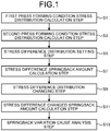
- a springback variation cause analysis method is a method for analyzing, when variation occurs in springback amount in a press forming part due to scattering or variation under press forming conditions, a portion in the press forming part that is a cause of the variation in springback amount, and includes, as illustrated in FIG. 1 , a first press forming condition stress distribution calculation step S1, a second press forming condition stress distribution calculation step S3, a stress difference distribution setting step S5, a stress difference springback amount calculation step S7, a stress difference distribution changing step S9, a stress difference changed springback amount calculation step S11, and a springback variation cause analysis step S13.
- the first press forming condition stress distribution calculation step S1 is a step for performing press forming analysis under first press forming conditions, which are set in advance as scattering or variation in press forming conditions, and calculating stress distribution in the press forming part 1 at the press forming bottom dead center.
- the material strengths of material A illustrated in Table 1 were set as the first press forming conditions.
- the press forming analysis at the first press forming condition stress distribution calculation step S1 is performed such that a blank model 9 as a press forming metallic sheet (steel sheet) is sandwiched by a tool of press forming model 3 consisting a die 5 and a punch 7, and as illustrated in (a) of FIG. 3 , the stress distribution in the press forming part 1 at the press forming bottom dead center is calculated.
- the blank model 9 was fixed by positioning pins in the course of press forming as illustrated in FIG.
- the element size of the blank model 9 was about 1 mm
- the friction coefficient between the blank model 9 and the tool of press forming model 3 was set to 0.15 while the position of the press forming bottom dead center was set such that a gap between models of upper and lower tools of press forming was 1.45 mm.
- a computer performs the press forming analysis.
- the press forming analysis for example, finite element analysis software can be used.
- LS-DYNA Ver.971 which is commercially available finite element analysis software, was executed on the computer to perform the press forming analysis, and a dynamic explicit method was applied to a solver.
- the present invention is not limited to the case where the tool of press forming model 3 as illustrated in FIG. 2 is used and the case where the press forming part 1 having the hat cross-sectional shape is to be press formed.
- the present invention can appropriately set the tool of press forming model and the press forming part depending on the press forming target.
- the second press forming condition stress distribution calculation step S3 is a step for performing press forming analysis under second press forming conditions that are set differently from the first press forming conditions set at the first press forming condition stress distribution calculation step S1 as scattering or variation in press forming conditions, and calculating a stress distribution in the press forming part 1 at the press forming bottom dead center.
- the material strengths of material B illustrated in Table 1 were set as the second press forming conditions.
- the press forming analysis at the second press forming condition stress distribution calculation step S3 is performed under the second press forming conditions as exemplified in FIG. 2 such that the blank model 9 is sandwiched by the tool-of-press-forming model 3 consisting the die 5 and the punch 7, and as illustrated in FIG. 4(a) , the stress distribution in the press forming part 1 at the press forming bottom dead center is calculated.
- a computer performs the press forming analysis.
- LS-DYNA Ver.971 which is commercially available finite element analysis software, was used to execute the press forming analysis.
- the stress difference distribution setting step S5 is a step for calculating difference between the stress distribution ((a) of FIG. 6 ) calculated at the second press forming condition stress distribution calculation step S3 and the stress distribution ((b) of FIG. 6 ) calculated at the first press forming condition stress distribution calculation step S1 as stress difference distribution, and replacing and setting the stress distribution in the press forming part 1 at the press forming bottom dead center calculated at the first press forming condition stress distribution calculation step S1 or the stress distribution in the press forming part 1 at the press forming bottom dead center calculated at the second press forming condition stress distribution calculation step S3 with the calculated stress difference distribution ((c) of FIG. 6 ).
- the stress difference springback amount calculation step S7 is a step for performing springback analysis on a press forming part for which the stress difference distribution has been set at the stress difference distribution setting step S5, and calculating springback amount to be caused in the press forming part.
- springback analysis is performed on a press forming part 1 ((a) of FIG. 7 ) for which the stress difference distribution has been set, and displacement ((b) of FIG. 7 ) after springback is calculated by the springback analysis.
- the springback analysis as illustrated in FIG. 9 , three locations provided on one end side of the press forming part 1 were constrained as constraint points, and the displacement caused by springback was calculated.
- a computer performs the springback analysis.
- finite element analysis software can be used.
- LS-DYNA Ver.971 which is commercially available finite element analysis software, was executed on the computer to perform the press forming analysis, and a static implicit method was applied to a solver.
- a torsion angle ((a) of FIG. 10 ) and a warping amount ((b) of FIG. 10 ) were calculated based on the displacement calculated by the springback analysis.
- the torsion angle was a rotation angle (positive in arrow direction in (a) of FIG. 10 ) caused by springback in a straight line connecting evaluation points at two locations provided on the other end side of the press forming part 1.
- the warping amount was a displacement amount (positive in direction away from die 5) in a press forming stroke direction at a middle point between the two evaluation points.
- the stress difference distribution changing step S9 is a step for changing the values of stress differences in a portion at a part of the press forming part in the stress difference distribution set for the press forming part at the stress difference distribution setting step S5.
- the press forming part 1 is divided into a plurality of areas (into six of A to F in longitudinal direction and into three of 1 to 3 in width direction) as illustrated in FIG. 11 , and stress differences in the areas are removed, that is, the values of the stress differences are set to zero.
- the stress difference changed springback amount calculation step S11 is a step for performing springback analysis on the press forming part for which the values of stress differences have been changed at the stress difference distribution changing step S9, and calculating springback amount.
- springback analysis is performed on the press forming part 1 by setting the values of stress differences in the areas (A1, A2, A3, ..., F3) divided as illustrated in FIG. 11 to zero, and the torsion angle and the warping amount are calculated as springback amount as illustrated in FIG. 10 .
- the value of stress difference is not necessarily required to be set to zero, and the value of stress difference may be changed.
- a computer performs the springback analysis.
- LS-DYNA Ver.971 which is commercially available finite element analysis software, was used.
- FIG. 12 to FIG. 29 illustrate the results of displacement due to springback calculated by performing springback analysis on the press forming part 1 by removing the stress differences (setting values of stress differences to zero) in the areas (A1, A2, A3, ..., F3) in the press forming part 1.
- the springback variation cause analysis step S13 is a step for analyzing, based on the springback amount calculated at the stress difference changed springback amount calculation step S11 and the springback amount calculated at the stress difference springback amount calculation step S7, a portion in the press forming part that is a cause of variation in springback amount in the press forming part due to scattering or variation in press forming conditions.
- FIG. 30 illustrates the results of the torsion angles calculated at the stress difference changed springback amount calculation step S11 and the torsion angle calculated at the stress difference springback amount calculation step S7.
- “base” indicates the torsion angle calculated at the stress difference springback amount calculation step S7 without changing the distribution of stress difference
- A1 to F3 indicate the torsion angles calculated at the stress difference changed springback amount calculation step S11 by removing the stress differences in the areas A1 to F3 illustrated in FIG. 11 .
- the torsion angle when the stress difference in the area A3 was removed was 1.87°, which increases as compared with the case where the stress difference is not changed ("base"), that is, the torsion angle (1.32°) caused by scattering in material strength of the press forming metallic sheet.
- base the case where the stress difference is not changed
- the torsion angle (1.32°) caused by scattering in material strength of the press forming metallic sheet is 1.87°, which increases as compared with the case where the stress difference is not changed (“base"), that is, the torsion angle (1.32°) caused by scattering in material strength of the press forming metallic sheet.
- base the stress difference is not changed
- the torsion angles in areas other than the areas A1, B3, and E2 and the area A3 are substantially equal to the torsion angle when the stress difference is not changed.
- the areas are portions where the influence on the variation in torsion angle caused by scattering of the material strength is small.
- the case where the torsion angle becomes lower than "base” by changing the value of the stress difference at the portion to zero indicates that the stress difference at the portion is a cause of the variation in springback to increase the torsion angle.
- the case where the torsion angle becomes larger than "base” by changing the value of the stress difference at the portion to zero indicates that the torsion angle is suppressed due to the presence of the stress difference at the portion, and hence the portion is determined to be an area that has no influence on the variation in springback.
- FIG. 31 illustrates results of the warping amounts calculated at the stress difference changed springback calculation step S11 and the warping amounts calculated at the stress difference springback calculation step S7.
- base indicates the warping amount calculated at the stress difference springback calculation step S7 without changing the distribution of stress difference
- A1 to F3 indicate the warping amounts calculated at the stress difference changed springback calculation step S11 by removing the stress differences in the areas A1 to F3 illustrated in FIG. 11 .
- the portion analyzed as a cause of the variation in springback amount due to scattering in material strength does not necessarily match a portion analyzed as a cause of the generation of springback itself by the conventional technology as described above. This point is described by comparison with the results of analyzing a cause of generation of springback by the conventional technology.
- FIG. 32 illustrates, as an example of a result of analyzing a portion that is a cause of generation of springback by conventional technology, the result of using the conventional technology (method disclosed in Patent Literature 1) to determine a relation between areas in which stress distribution at the press forming bottom dead center was changed and torsion angles caused by springback when the stress distribution was changed.
- FIG. 32 illustrates the results of the torsion angle in the case where the stress distribution at the press forming bottom dead center was not changed ("base") and the torsion angles calculated by performing springback analysis by removing the stresses in the areas A1 to F3 illustrated in FIG. 11 .
- portions that are causes of generation of springback can be analyzed to be portions corresponding to the areas A3, B1, B2, and E2 in which the difference from the torsion angle in "base" is large.
- the analyzed portions indicate tendencies different from a portion that is a cause of variation in torsion angle due to scattering in material strength.
- the areas A1, B3, and E2 in the press forming part 1 were analyzed as portions to be causes of variation in springback amount. Whether the variation in springback amount was reduced by changing the stress distribution at the analyzed portion was verified.
- the stress distribution in the areas A1, B3, and E2 in the press forming part 1 determined under the press forming conditions of the material B was replaced with the stress distribution determined under the press forming conditions of the material A, and springback analysis was performed to calculate displacement due to springback. Displacement calculated by the springback analysis in which the stress distribution in each area was replaced was used to calculate the torsion angle caused in the press forming part 1.
- FIG. 33 to FIG. 35 illustrate the results of displacement calculated by springback analysis in which the stress distribution in the areas A1, B3, and E2 was replaced with the stress distribution determined under the press forming conditions of the material A.
- FIG. 36 illustrate the result of displacement calculated by performing springback analysis by replacing the stress distribution in all the areas A1, B3, and E2 with the stress distribution in the material A.
- FIG. 37 illustrates the results of torsion angles determined by the displacement ( FIG. 33 to FIG. 36 ) calculated by replacing the stresses in the areas
- FIG. 38 illustrates the results of variation amounts of torsion angles determined by the displacement ( FIG. 33 to FIG. 36 ) calculated by replacing the stresses in the areas.
- the method according to the first embodiment can accurately analyze a portion that is a cause of variation in springback amount due to scattering in press forming conditions.
- a springback variation cause analysis method is a method for analyzing, when variation occurs in springback amount in a press forming part due to scattering or variation in press forming conditions, a portion in the press forming part that is a cause of the variation in springback amount.
- the springback variation cause analysis method includes a first press forming part stress distribution acquisition step S21, a second press forming part stress distribution acquisition step S23, a stress difference distribution setting step S25, a stress difference springback amount calculation step S27, a stress difference distribution changing step S29, a stress difference changed springback amount calculation step S31, and a springback variation cause analysis step S33.
- the above-mentioned steps are described with reference to FIG. 39 and FIG. 40 .
- the first press forming part stress distribution acquisition step S21 is a step for press forming a first press forming part under first press forming conditions in advance, creating a first press forming part model from three-dimensional shape measurement data obtained by measuring the surface shape of the first press forming part after die release, performing mechanical analysis in the state in which the first press forming part model is sandwiched by a tool-of-press-forming model until reaching a press forming bottom dead center, and acquiring stress distribution in the first press forming part model at the press forming bottom dead center.
- Specific processing at the first press forming part stress distribution acquisition step S21 corresponds to, as illustrated in FIG. 40 , a process for press forming a first press forming part 21 under first press forming conditions by using a tool of press forming 11, measuring the three-dimensional shape of the press-formed first press forming part 21, processing measured first press forming part three-dimensional shape data 23 to create a first press forming part model 25, performing elastic finite element analysis as mechanical analysis in the state in which the first press forming part model 25 is sandwiched by a tool-of-press-forming model 41 consisting a die 43 and a punch 45 until reaching a press forming bottom dead center, and acquiring stress distribution in the first press forming part model 25 at the press forming bottom dead center obtained by the elastic finite element analysis.
- Patent Literature 7 As specific methods for the measurement of the three-dimensional shape of the first press forming part 21, the creation of the first press forming part model 25, and the elastic finite element analysis, for example, the methods disclosed in Patent Literature 7 can be used.
- the second press forming part stress distribution acquisition step S23 is a step for press forming a second press forming part under second press forming conditions different from the first press forming conditions, creating a second press forming part model from three-dimensional shape measurement data obtained by measuring the surface shape of the second press forming part after die release, performing mechanical analysis in the state in which the second press forming part model is sandwiched by the tool-of-press-forming model until reaching the press forming bottom dead center, and acquiring stress distribution in the second press forming part model at the press forming bottom dead center.
- Specific processing at the second press forming part stress distribution acquisition step S23 also corresponds to, as illustrated in FIG. 40 , a process for press forming a second press forming part 31 under second press forming conditions by using the tool of press forming 11, measuring the three-dimensional shape of the press-formed second press forming part 31, processing measured second press forming part three-dimensional shape data 33 to create a second press forming part model 35, and performing elastic finite element analysis as mechanical analysis in the state in which the second press forming part model 35 is sandwiched by the tool-of-press-forming model 41 consisting the die 43 and the punch 45 until reaching the press forming bottom dead center.
- the creation of the second press forming part model 35, and the elastic finite element analysis for example, the methods disclosed in Patent Literature 7 can also be used.
- the stress difference distribution setting step S25 is a step for calculating difference between the stress distribution in the first press forming part model 25 at the press forming bottom dead center calculated at the first press forming part stress distribution acquisition step S21 and the stress distribution in the second press forming part model 35 at the press forming bottom dead center calculated at the second press forming part stress distribution acquisition step S23 as stress difference distribution, and replacing and setting the stress distribution in the first press forming part model 25 at the press forming bottom dead center acquired at the first press forming part stress distribution acquisition step S21 or the stress distribution in the second press forming part model 35 at the press forming bottom dead center acquired at the second press forming part stress distribution acquisition step S23 with the calculated stress difference distribution.
- the difference between the stress distribution in the first press forming part model 25 at the press forming bottom dead center and the stress distribution in the second press forming part model 35 at the press forming bottom dead center is calculated as stress difference distribution, and the calculated stress difference distribution is set to the first press forming part model 25 at the press forming bottom dead center.
- the stress difference distribution may be set to the second press forming part model 35 at the press forming bottom dead center.
- the stress difference springback amount calculation step S27 is a step for performing springback analysis on the first press forming part model 25 based on the stress difference distribution set at the stress difference distribution setting step S25, and calculating springback amount to be caused in the first press forming part model 25.
- a computer performs the springback analysis.
- finite element analysis software can be used.
- LS-DYNA Ver.971 which is commercially available finite element analysis software, was executed on the computer to perform the press forming analysis, and a static implicit method was applied to a solver.
- the stress difference distribution changing step S29 is a step for changing the values of stress differences at a part of the first press forming part model or the second press forming part model in the stress difference distribution set for the first press forming part model or the second press forming part model at the stress difference distribution setting step S5.
- the first press forming part model 25 for which the stress difference distribution has been set at the stress difference distribution setting step S5 is divided into a plurality of areas (into six of A to F in longitudinal direction and into three of 1 to 3 in width direction) as illustrated in FIG. 11 , and stress differences in the areas are removed (set to zero).
- the stress difference changed springback amount calculation step S31 is a step for performing springback analysis on the first press forming part model or the second press forming part model for which the values of stress differences have been changed at the stress difference distribution changing step S29, and calculating springback amount.
- springback analysis is performed on the first press forming part model 25 for which the value of the stress difference distribution has been changed at the stress difference distribution changing step S29.
- a computer performs the springback analysis.
- the springback analysis for example, finite element analysis software can be used.
- the springback variation cause analysis step S33 is a step for analyzing, based on the springback amount calculated at the stress difference changed springback amount calculation step S31 and the springback amount calculated at the stress difference springback amount calculation step S27, a portion in the first press forming part model 25 that is a cause of variation in springback amount in the first press forming part model 25 due to scattering or variation in press forming conditions.
- the method according to the second embodiment indicates that a portion that is a cause of variation in springback amount due to scattering or variation in press forming conditions was accurately analyzed.
- Patent Literature 7 discloses a method for calculating stress distribution at the press forming bottom dead center by acquiring the measured shape of a press forming part and performing mechanical analysis in which the press forming part is sandwiched by the shape of a tool of press forming based on the acquired measured shape.
- Patent Literature 7 does not indicate or suggest that, as in the method according to the second embodiment, difference in stress distribution at the press forming bottom dead center in two press forming parts press formed under two press forming conditions is determined, and variation in springback amount due to scattering or variation in press forming conditions is evaluated based on the difference in stress distribution.
- the press forming conditions that cause scattering or variation in the first embodiment and the second embodiment are any one of mechanical properties of a press forming metallic sheet (blank), the thickness and shape of the press forming metallic sheet, the temperature of the press forming metallic sheet, sliding characteristics between the press forming metallic sheet and a tool of press forming, the relative position of the press forming metallic sheet with respect to the tool of press forming, the position and shape of a positioning device for the press forming metallic sheet, mechanical properties of press forming tool material, the shape of the surface of the tool of press forming, the internal structure of the tool of press forming, blank holder force, blank holder position, the position and shape of a device for applying blank holder force to component parts of the tool of press forming, the initial relative position of the component parts of the tool of press forming, the relative speed of movement of the tool of press forming, the vibration of the tool of press forming, the temperature of the tool of press forming, atmospheric temperature, atmospheric components, a pressurizing device, and electromagnetic environments.
- the stress difference in at least a partial area of the stress difference distribution is removed (all components are set to zero).
- the method for changing the stress difference is not limited thereto, and the stress difference only needs to be changed by removing a component of the stress difference in at least one direction, constant multiplication, addition of a constant, constant power, replacement with average value in sheet thickness direction of the press forming metallic sheet, and replacement with a median value in the sheet thickness direction.
- the method according to the above-mentioned first embodiment was used. Specifically, as illustrated in FIG. 2 , press forming analysis in which the tool-of-press-forming model 3 consisting the die 5 and the punch 7 was used to press form the blank model 9 into the press forming part 1 and springback analysis on the press forming part 1 for which stress difference distribution at the press forming bottom dead center determined by the press forming analysis was set were performed. In regard to the analysis of a portion in which variation occurs in springback amount, by dividing the press forming part 1 into a plurality of areas as illustrated in FIG. 11 and removing the stress differences in the areas (set to zero), the relation between the area in which the stress difference was changed and the springback amount when the stress difference in the area was changed was determined. The press forming analysis and the springback analysis were performed by executing LS-DYNA Ver.971 as finite element analysis software on a computer.
- Scattering in shape of the tool of press forming means the case where the curvature radii of ridge lines of the die 5 and the punch 7 increase due to wear of the tool of press forming during mass production.
- Two conditions were set: a condition in which the curvature radii of all ridge lines of the die 5 and the punch 7 in the tool-of-press-forming model 3 remain unchanged from the design shape (hereinafter referred to as "tool of press forming A") and a condition in which the curvature radii are increased by 2 mm (hereinafter referred to as "tool of press forming B").
- the curvature radius of 2 mm was set as a value larger than actual variation.
- Press forming analysis was performed on the shape of each tool of press forming, and the difference in stress distribution at the press forming bottom dead center was calculated to analyze a portion as a cause of variation in springback amount.
- the press forming conditions such as an amount of lubricant and a press forming bottom dead center position
- the friction coefficient between the blank model 9 and the tool-of-press-forming model 3 was set to 0.15
- the press forming bottom dead center position was set such that the gap between the die 5 and the punch 7 was 1.45 mm.
- FIG. 41 illustrate stress distribution (a) at the press forming bottom dead center calculated by performing press forming analysis under press forming conditions of a tool of press forming B and displacement (b) in the press forming part 1 calculated by springback analysis based on the stress distribution.
- the stress distribution at the press forming bottom dead center calculated by press forming analysis under the press forming conditions of the tool of press forming A and the displacement in the press forming part 1 calculated by springback analysis are the same as the results illustrated in FIG. 3 .
- FIG. 42 illustrate difference (a) between the stress distributions at the press forming bottom dead center calculated under the press forming conditions of the tool of press forming A and the tool of press forming B and displacement (b) in the press forming part 1 calculated by springback analysis using the stress difference distribution.
- FIG. 43 illustrate difference in displacement caused by scattering in press forming conditions of the tool of press forming B and the tool of press forming A that were calculated by springback analysis based on the stress distributions at the press forming bottom dead center calculated under press forming conditions of the tool of press forming A and the tool of press forming B.
- the distribution of displacement based on the stress difference distribution ((b) of FIG. 42 ) and the difference in displacement based on the stress distributions ((b) of FIG. 43 ) have substantially the same tendency. This indicates that stress difference distribution as difference in stress distribution at the press forming bottom dead center under two conditions with different shapes of tools of press forming as scattering in press forming conditions is a cause of variation in springback amount.
- FIG. 44 and FIG. 45 illustrate the results of torsion angles and warping amounts as springback amount determined by using the displacement calculated by performing springback analysis based on the stress difference distribution.
- base indicates the springback amount calculated at the stress difference springback amount calculation step S7 without changing the distribution of stress difference
- A1 to F3 indicate the springback amount calculated at the stress difference changed springback amount calculation step S11 by removing the stress differences in the areas A1 to F3 illustrated in FIG. 11 .
- the torsion angle is greatly reduced to 0.00° as compared with a torsion angle of 0.40° before the stress difference is removed.
- the area B3 is analyzed as a portion that is a cause of variation in torsion angle.
- the warping amounts are changed to -1.58 mm and 0.17 mm, respectively, as compared with a warping amount of -2.99 mm before the stress differences are removed, and the absolute values thereof are greatly reduced.
- the areas D2 and E2 are analyzed as portions that are causes of the variation in warping amount.
- portions that are causes of variation in torsion angle and warping amount as springback amount due to scattering in the shape of the tool of press forming can be analyzed.
- a press forming part in which shape variation due to scattering in press forming conditions can be obtained.
- press forming analysis was performed under press forming conditions in which the friction coefficient was 0.15 (hereinafter referred to as "lubrication A”) and press forming conditions in which the friction coefficient was 0.20 (hereinafter referred to as "lubrication B”), and the difference in stress distribution at the press forming bottom dead center was calculated to analyze a portion as a cause of variation in springback amount.
- the method described in the first embodiment was used, and the press forming bottom dead center position was set such that the gap between the die 5 and the punch 7 in the tool-of-press-forming model 3 was 1.45 mm on the assumption that the press forming conditions (such as a shape of tool of press forming and a press forming bottom dead center position) other than the lubricating conditions were not changed.
- FIG. 46 illustrate stress distribution (a) at the press forming bottom dead center when press forming analysis was performed under press forming conditions of the lubrication B and displacement (b) in the press forming part 1 calculated by springback analysis based on the stress distribution.
- the stress distribution at the press forming bottom dead center when press forming analysis was performed under the press forming conditions of the lubrication A and the displacement in the press forming part 1 calculated by springback analysis are the same as the results illustrated in FIG. 3 .
- FIG. 47 illustrate difference (a) in stress distribution at the press forming bottom dead center calculated under press forming conditions of lubrication A and lubrication B and displacement (b) in the press forming part 1 calculated by springback analysis using the stress difference distribution.
- FIG. 48 illustrate difference between the displacement calculated by performing springback analysis under the press forming conditions of the lubrication A and the displacement calculated by performing springback analysis under the press forming conditions of the lubrication B.
- the distribution of displacement based on the stress difference distribution ((b) of FIG. 47 ) and the distribution of difference in displacement based on the stress distribution ((b) of FIG. 48 ) have similar tendencies. This indicates that even when scattering occurs in lubricating conditions as press forming conditions, the difference in press forming bottom dead center stress distribution when the lubricating conditions are different, that is, the stress difference distribution is a cause of variation in springback amount.
- FIG. 49 and FIG. 50 illustrate the results of determining the torsion angle and the warping amount as springback amount by using displacement calculated by performing springback analysis based on the stress difference distribution.
- base indicates the springback amount calculated at the stress difference springback amount calculation step S7 without changing the distribution in stress difference
- A1 to F3 indicate the springback amount calculated at the stress difference changed springback amount calculation step S11 by removing the stress differences in the areas A1 to F3 illustrated in FIG. 11 .
- press forming analysis was performed under press forming conditions where the gap between the die 5 and the punch 7 in the tool-of-press-forming model 3 was 1.45 mm (hereinafter referred to as "bottom dead center A") and press forming conditions where the gap between the die 5 and the punch 7 increased by 0.2 mm to be 1.65 mm (hereinafter referred to as "bottom dead center B”), and the difference in stress distribution in press forming bottom dead center was calculated to analyze a portion that was a cause of variation in springback amount.
- bottom dead center A the gap between the die 5 and the punch 7 in the tool-of-press-forming model 3
- bottom dead center B press forming conditions where the gap between the die 5 and the punch 7 increased by 0.2 mm to be 1.65 mm
- the method described in the first embodiment was used, and the friction coefficient between the blank model 9 and the tool-of-press-forming model 3 was set to 0.15 on the assumption that the press forming conditions (such as shape of tool of press forming and amount of lubricant (friction coefficient)) other than the press forming bottom dead center position were not changed.
- the press forming conditions such as shape of tool of press forming and amount of lubricant (friction coefficient)
- FIG. 51 illustrate stress distribution (a) at the press forming bottom dead center when press forming analysis was performed under press forming conditions of the bottom dead center B and displacement (b) in the press forming part 1 calculated by springback analysis based on the stress distribution.
- the stress distribution at the press forming bottom dead center when press forming analysis was performed under the press forming conditions of the bottom dead center A and the displacement in the press forming part 1 calculated by springback analysis are the same as the results illustrated in FIG. 3 .
- FIG. 52 illustrate difference (a) between the stress distributions at the press forming bottom dead center calculated under the press forming conditions of the bottom dead center A and the bottom dead center B and displacement (b) in the press forming part 1 calculated by springback analysis using the stress difference distribution.
- FIG. 53 illustrate difference between the displacement calculated by performing springback analysis under the press forming conditions of the bottom dead center A and the displacement calculated by performing springback analysis under the press forming conditions of the bottom dead center B.
- the distribution of displacement based on the stress difference distribution ((b) of FIG. 52 ) and the distribution of difference in displacement based on the stress distribution ((b) of FIG. 53 ) have substantially the same tendency. This indicates that even when scattering occurs in the position of bottom dead center as press forming conditions, the difference in press forming bottom dead center stress distribution when the bottom dead center positions are different, that is, the stress difference distribution is a cause of variation in springback amount.
- FIG. 54 and FIG. 55 illustrate the results of determining torsion angles and warping amounts as springback amount by using the displacement calculated by performing springback analysis based on the stress difference distribution.
- “base” indicates the springback amount calculated at the stress difference springback amount calculation step S7 without changing the distribution of stress difference
- A1 to F3 indicate the springback amount calculated at the stress difference changed springback amount calculation step S11 by removing the stress differences in the areas A1 to F3 illustrated in FIG. 11 .
- the springback variation cause analysis method for analyzing a portion in which scattering or variation in press forming conditions causes variation in springback amount can be provided.
Landscapes
- Engineering & Computer Science (AREA)
- Physics & Mathematics (AREA)
- Theoretical Computer Science (AREA)
- General Physics & Mathematics (AREA)
- Mechanical Engineering (AREA)
- Computer Hardware Design (AREA)
- Evolutionary Computation (AREA)
- Geometry (AREA)
- General Engineering & Computer Science (AREA)
- Aviation & Aerospace Engineering (AREA)
- Shaping Metal By Deep-Drawing, Or The Like (AREA)
Priority Applications (1)
| Application Number | Priority Date | Filing Date | Title |
|---|---|---|---|
| EP21215955.2A EP3991872B1 (fr) | 2017-12-07 | 2018-10-19 | Procédé d'analyse de cause de variation de retour élastique |
Applications Claiming Priority (2)
| Application Number | Priority Date | Filing Date | Title |
|---|---|---|---|
| JP2017235121A JP6519639B1 (ja) | 2017-12-07 | 2017-12-07 | スプリングバック量変動要因部位特定方法 |
| PCT/JP2018/039022 WO2019111555A1 (fr) | 2017-12-07 | 2018-10-19 | Procédé d'analyse de cause de variation de retour élastique |
Related Child Applications (1)
| Application Number | Title | Priority Date | Filing Date |
|---|---|---|---|
| EP21215955.2A Division EP3991872B1 (fr) | 2017-12-07 | 2018-10-19 | Procédé d'analyse de cause de variation de retour élastique |
Publications (2)
| Publication Number | Publication Date |
|---|---|
| EP3722016A1 true EP3722016A1 (fr) | 2020-10-14 |
| EP3722016A4 EP3722016A4 (fr) | 2021-08-18 |
Family
ID=66655634
Family Applications (2)
| Application Number | Title | Priority Date | Filing Date |
|---|---|---|---|
| EP21215955.2A Active EP3991872B1 (fr) | 2017-12-07 | 2018-10-19 | Procédé d'analyse de cause de variation de retour élastique |
| EP18886420.1A Pending EP3722016A4 (fr) | 2017-12-07 | 2018-10-19 | Procédé d'analyse de cause de variation de retour élastique |
Family Applications Before (1)
| Application Number | Title | Priority Date | Filing Date |
|---|---|---|---|
| EP21215955.2A Active EP3991872B1 (fr) | 2017-12-07 | 2018-10-19 | Procédé d'analyse de cause de variation de retour élastique |
Country Status (7)
| Country | Link |
|---|---|
| US (1) | US11221272B2 (fr) |
| EP (2) | EP3991872B1 (fr) |
| JP (1) | JP6519639B1 (fr) |
| KR (1) | KR102418207B1 (fr) |
| CN (1) | CN111432952B (fr) |
| MX (1) | MX2020005963A (fr) |
| WO (1) | WO2019111555A1 (fr) |
Families Citing this family (16)
| Publication number | Priority date | Publication date | Assignee | Title |
|---|---|---|---|---|
| JP6683269B1 (ja) * | 2019-02-01 | 2020-04-15 | Jfeスチール株式会社 | スプリングバック量変動要因部位特定方法 |
| JP6852750B2 (ja) | 2019-04-25 | 2021-03-31 | Jfeスチール株式会社 | スプリングバック量乖離要因部位特定方法および装置 |
| KR102833603B1 (ko) * | 2020-03-09 | 2025-07-11 | 코우리츠 다이가꾸 호우진 오사카 | 선상 가열에 의한 금속판의 굽힘 가공에 사용하는 가열방안의 산출방법 |
| CN112035914B (zh) * | 2020-07-17 | 2023-12-22 | 中国二十冶集团有限公司 | 一种外弧切线电算组合建模精细化调整方法 |
| JP7543129B2 (ja) * | 2020-12-28 | 2024-09-02 | 株式会社日立製作所 | 材料の加工方法並びにプロセス設計計算機及びそのプログラム |
| CN116060520B (zh) * | 2021-11-04 | 2026-02-17 | 宝山钢铁股份有限公司 | 一种金属板材冲压成形件回弹控制方法及冲压模具 |
| JP7306558B1 (ja) * | 2022-01-11 | 2023-07-11 | Jfeスチール株式会社 | プレス成形品の外周形状評価方法、装置及びプログラム、並びにプレス成形品の製造方法 |
| JP7276584B1 (ja) * | 2022-01-11 | 2023-05-18 | Jfeスチール株式会社 | プレス成形品のスプリングバック量評価方法、装置及びプログラム、並びにプレス成形品の製造方法 |
| US20250053706A1 (en) * | 2022-01-17 | 2025-02-13 | Jfe Steel Corporation | Press forming analysis method, press forming analysis apparatus, and press forming analysis program |
| JP7533495B2 (ja) * | 2022-01-25 | 2024-08-14 | Jfeスチール株式会社 | プレス成形品の外周形状評価方法、装置及びプログラム |
| CN114769390B (zh) * | 2022-06-17 | 2022-09-09 | 南通瑞卓不锈钢制品有限公司 | 大容量不锈钢水箱冲压工艺自适应调节方法 |
| JP7409583B1 (ja) * | 2022-07-22 | 2024-01-09 | Jfeスチール株式会社 | プレス成形品の製造方法 |
| KR20250038762A (ko) * | 2022-08-19 | 2025-03-19 | 제이에프이 스틸 가부시키가이샤 | 프레스 성형품의 제조 방법 |
| JP7420190B1 (ja) * | 2022-10-05 | 2024-01-23 | Jfeスチール株式会社 | 成形荷重増要因部位特定方法、プレス成形品の製造方法、成形荷重増要因部位特定装置、成形荷重増要因部位特定プログラム |
| CN115283474B (zh) * | 2022-10-08 | 2023-01-24 | 中北大学 | 一种高性能板坯均匀正挤压控制成形模具 |
| JP7529069B1 (ja) * | 2023-02-09 | 2024-08-06 | Jfeスチール株式会社 | プレス成形シミュレーション解析方法、装置及びプログラム、並びにプレス成形品の製造方法 |
Family Cites Families (16)
| Publication number | Priority date | Publication date | Assignee | Title |
|---|---|---|---|---|
| CA2613845C (fr) * | 2005-06-30 | 2011-03-15 | Nippon Steel Corporation | Methode et dispositif de designation de membre, programme informatique et support d'enregistrement lisible par ordinateur |
| JP4894294B2 (ja) * | 2006-02-27 | 2012-03-14 | Jfeスチール株式会社 | プレス成形解析方法 |
| JP4739147B2 (ja) | 2006-08-28 | 2011-08-03 | トヨタ自動車株式会社 | 形状不良要因特定方法、装置及びプログラム |
| CN103995927B (zh) * | 2006-08-31 | 2017-01-04 | 新日铁住金株式会社 | 回弹对策位置特定方法以及回弹对策位置特定装置 |
| JP4418452B2 (ja) | 2006-10-02 | 2010-02-17 | 新日本製鐵株式会社 | スプリングバック発生原因部位特定方法、その装置、及びそのプログラム |
| JP4344375B2 (ja) | 2006-09-29 | 2009-10-14 | 新日本製鐵株式会社 | スプリングバック発生原因部位特定方法、その装置、及びそのプログラム |
| JP4724626B2 (ja) | 2006-08-31 | 2011-07-13 | 新日本製鐵株式会社 | スプリングバック発生原因部位特定方法、その装置、及びそのプログラム |
| JP4410833B2 (ja) * | 2007-12-25 | 2010-02-03 | 新日本製鐵株式会社 | スプリングバック発生原因分析方法、その装置、そのプログラム及び記録媒体 |
| JP2011183417A (ja) * | 2010-03-05 | 2011-09-22 | Nippon Steel Corp | スプリングバック安定性評価方法 |
| JP5765014B2 (ja) | 2011-03-30 | 2015-08-19 | Jfeスチール株式会社 | プレス成形解析方法 |
| JP5821403B2 (ja) * | 2011-08-22 | 2015-11-24 | Jfeスチール株式会社 | プレス成形品のスプリングバック対策効果確認方法及び装置 |
| JP5834698B2 (ja) | 2011-09-26 | 2015-12-24 | Jfeスチール株式会社 | プレス成形におけるスプリングバック要因分析方法及び装置 |
| JP6060591B2 (ja) | 2012-09-26 | 2017-01-18 | Jfeスチール株式会社 | プレス成形品のスプリングバック要因特定方法および装置 |
| CN105188978B (zh) * | 2013-02-08 | 2017-03-29 | 杰富意钢铁株式会社 | 冲压成型解析方法 |
| JP6152841B2 (ja) * | 2014-10-31 | 2017-06-28 | Jfeスチール株式会社 | プレス成形方法およびプレス成形用金型の製造方法 |
| KR101953501B1 (ko) | 2015-01-26 | 2019-02-28 | 신닛테츠스미킨 카부시키카이샤 | 면 형상 불량 발생 영역 추정 방법, 면 형상 불량 원인 영역 추정 방법, 면 형상 불량 발생 영역 추정 장치, 면 형상 불량 원인 영역 추정 장치, 프로그램, 및 기록 매체 |
-
2017
- 2017-12-07 JP JP2017235121A patent/JP6519639B1/ja active Active
-
2018
- 2018-10-19 MX MX2020005963A patent/MX2020005963A/es unknown
- 2018-10-19 CN CN201880078293.1A patent/CN111432952B/zh active Active
- 2018-10-19 US US16/768,132 patent/US11221272B2/en active Active
- 2018-10-19 WO PCT/JP2018/039022 patent/WO2019111555A1/fr not_active Ceased
- 2018-10-19 EP EP21215955.2A patent/EP3991872B1/fr active Active
- 2018-10-19 EP EP18886420.1A patent/EP3722016A4/fr active Pending
- 2018-10-19 KR KR1020207019273A patent/KR102418207B1/ko active Active
Also Published As
| Publication number | Publication date |
|---|---|
| CN111432952B (zh) | 2022-01-18 |
| WO2019111555A1 (fr) | 2019-06-13 |
| CN111432952A (zh) | 2020-07-17 |
| MX2020005963A (es) | 2020-08-24 |
| JP6519639B1 (ja) | 2019-05-29 |
| US11221272B2 (en) | 2022-01-11 |
| US20200309635A1 (en) | 2020-10-01 |
| KR102418207B1 (ko) | 2022-07-06 |
| JP2019098390A (ja) | 2019-06-24 |
| KR20200092388A (ko) | 2020-08-03 |
| EP3991872A1 (fr) | 2022-05-04 |
| EP3722016A4 (fr) | 2021-08-18 |
| EP3991872B1 (fr) | 2025-12-03 |
Similar Documents
| Publication | Publication Date | Title |
|---|---|---|
| EP3991872B1 (fr) | Procédé d'analyse de cause de variation de retour élastique | |
| EP3919197A1 (fr) | Procédé d'identification d'une portion à facteur de variation d'une quantité de retour élastique | |
| JP4410833B2 (ja) | スプリングバック発生原因分析方法、その装置、そのプログラム及び記録媒体 | |
| EP3960320B1 (fr) | Méthode et dispositif d'identification d'une portion de facteur de divergence de quantité de rappel élastique | |
| Wang et al. | Investigation of die radius arc profile on wear behaviour in sheet metal processing of advanced high strength steels | |
| Phanitwong et al. | Development of anew spring-back factor for a wiping die bending process | |
| JP2019126831A (ja) | 金型摩耗量の予測方法とその予測プログラムおよび摩耗推定式の特定方法 | |
| JP6149843B2 (ja) | プレス成形品の形状矯正解析方法及び装置、プレス成形品の形状矯正方法 | |
| JP6303815B2 (ja) | 鍛造割れ予測方法、鍛造割れ予測プログラム、および記録媒体 | |
| EP3998123A1 (fr) | Procédé de production de matériau d'ébauche, procédé de production d'article formé à la presse, procédé de détermination de forme, programme de détermination de forme, appareil de production de matériau d'ébauche et matériau d'ébauche | |
| EP3975031A1 (fr) | Procédé et dispositif permettant d'identifier des sites provoquant une divergence de quantité de retour élastique | |
| EP4439372A1 (fr) | Procédé, dispositif et programme d'évaluation de la forme périphérique d'un article formé à la presse, et procédé de fabrication d'un article formé à la presse | |
| Elsayed et al. | An investigation and prediction of springback of sheet metals under cold forming condition | |
| JP2023102880A (ja) | プレス成形品のスプリングバック量評価方法、装置及びプログラム | |
| Phanitwong et al. | Finite element analysis of spring-back characteristics on asymmetrical Z-shape parts in wiping Z-bending process | |
| KR20260027291A (ko) | 압연 하중 분포 계산 방법, 압연 하중 계산 방법, 접촉 호 길이 계산 방법 및 압연 방법 | |
| JP2023108091A (ja) | プレス成形品の外周形状評価方法、装置及びプログラム | |
| Yang et al. | Finite element analysis of wear in piercing | |
| Chirita | influence of residual stress distribution in sheet metal forming |
Legal Events
| Date | Code | Title | Description |
|---|---|---|---|
| STAA | Information on the status of an ep patent application or granted ep patent |
Free format text: STATUS: THE INTERNATIONAL PUBLICATION HAS BEEN MADE |
|
| PUAI | Public reference made under article 153(3) epc to a published international application that has entered the european phase |
Free format text: ORIGINAL CODE: 0009012 |
|
| STAA | Information on the status of an ep patent application or granted ep patent |
Free format text: STATUS: REQUEST FOR EXAMINATION WAS MADE |
|
| 17P | Request for examination filed |
Effective date: 20200616 |
|
| AK | Designated contracting states |
Kind code of ref document: A1 Designated state(s): AL AT BE BG CH CY CZ DE DK EE ES FI FR GB GR HR HU IE IS IT LI LT LU LV MC MK MT NL NO PL PT RO RS SE SI SK SM TR |
|
| AX | Request for extension of the european patent |
Extension state: BA ME |
|
| DAV | Request for validation of the european patent (deleted) | ||
| DAX | Request for extension of the european patent (deleted) | ||
| REG | Reference to a national code |
Ref country code: DE Ref legal event code: R079 Free format text: PREVIOUS MAIN CLASS: B21D0022000000 Ipc: B21D0022220000 |
|
| A4 | Supplementary search report drawn up and despatched |
Effective date: 20210716 |
|
| RIC1 | Information provided on ipc code assigned before grant |
Ipc: B21D 22/22 20060101AFI20210712BHEP Ipc: G06F 30/23 20200101ALI20210712BHEP Ipc: G06F 113/24 20200101ALN20210712BHEP Ipc: G06F 119/14 20200101ALN20210712BHEP Ipc: G06F 119/18 20200101ALN20210712BHEP |
|
| STAA | Information on the status of an ep patent application or granted ep patent |
Free format text: STATUS: EXAMINATION IS IN PROGRESS |
|
| 17Q | First examination report despatched |
Effective date: 20231129 |