EP3720754B1 - Spindel und lenksäulenanordnung damit - Google Patents
Spindel und lenksäulenanordnung damit Download PDFInfo
- Publication number
- EP3720754B1 EP3720754B1 EP18826968.2A EP18826968A EP3720754B1 EP 3720754 B1 EP3720754 B1 EP 3720754B1 EP 18826968 A EP18826968 A EP 18826968A EP 3720754 B1 EP3720754 B1 EP 3720754B1
- Authority
- EP
- European Patent Office
- Prior art keywords
- inner tube
- connection portion
- tube
- attachment section
- section
- Prior art date
- Legal status (The legal status is an assumption and is not a legal conclusion. Google has not performed a legal analysis and makes no representation as to the accuracy of the status listed.)
- Active
Links
Images

Classifications
-
- B—PERFORMING OPERATIONS; TRANSPORTING
- B62—LAND VEHICLES FOR TRAVELLING OTHERWISE THAN ON RAILS
- B62D—MOTOR VEHICLES; TRAILERS
- B62D1/00—Steering controls, i.e. means for initiating a change of direction of the vehicle
- B62D1/02—Steering controls, i.e. means for initiating a change of direction of the vehicle vehicle-mounted
- B62D1/16—Steering columns
-
- B—PERFORMING OPERATIONS; TRANSPORTING
- B21—MECHANICAL METAL-WORKING WITHOUT ESSENTIALLY REMOVING MATERIAL; PUNCHING METAL
- B21D—WORKING OR PROCESSING OF SHEET METAL OR METAL TUBES, RODS OR PROFILES WITHOUT ESSENTIALLY REMOVING MATERIAL; PUNCHING METAL
- B21D39/00—Application of procedures in order to connect objects or parts, e.g. coating with sheet metal otherwise than by plating; Tube expanders
- B21D39/04—Application of procedures in order to connect objects or parts, e.g. coating with sheet metal otherwise than by plating; Tube expanders of tubes with tubes; of tubes with rods
-
- B—PERFORMING OPERATIONS; TRANSPORTING
- B23—MACHINE TOOLS; METAL-WORKING NOT OTHERWISE PROVIDED FOR
- B23P—METAL-WORKING NOT OTHERWISE PROVIDED FOR; COMBINED OPERATIONS; UNIVERSAL MACHINE TOOLS
- B23P11/00—Connecting or disconnecting metal parts or objects by metal-working techniques not otherwise provided for
- B23P11/02—Connecting or disconnecting metal parts or objects by metal-working techniques not otherwise provided for by first expanding and then shrinking or vice versa, e.g. by using pressure fluids; by making force fits
-
- B—PERFORMING OPERATIONS; TRANSPORTING
- B62—LAND VEHICLES FOR TRAVELLING OTHERWISE THAN ON RAILS
- B62D—MOTOR VEHICLES; TRAILERS
- B62D1/00—Steering controls, i.e. means for initiating a change of direction of the vehicle
- B62D1/02—Steering controls, i.e. means for initiating a change of direction of the vehicle vehicle-mounted
- B62D1/16—Steering columns
- B62D1/18—Steering columns yieldable or adjustable, e.g. tiltable
-
- B—PERFORMING OPERATIONS; TRANSPORTING
- B23—MACHINE TOOLS; METAL-WORKING NOT OTHERWISE PROVIDED FOR
- B23P—METAL-WORKING NOT OTHERWISE PROVIDED FOR; COMBINED OPERATIONS; UNIVERSAL MACHINE TOOLS
- B23P11/00—Connecting or disconnecting metal parts or objects by metal-working techniques not otherwise provided for
-
- B—PERFORMING OPERATIONS; TRANSPORTING
- B23—MACHINE TOOLS; METAL-WORKING NOT OTHERWISE PROVIDED FOR
- B23P—METAL-WORKING NOT OTHERWISE PROVIDED FOR; COMBINED OPERATIONS; UNIVERSAL MACHINE TOOLS
- B23P2700/00—Indexing scheme relating to the articles being treated, e.g. manufactured, repaired, assembled, connected or other operations covered in the subgroups
- B23P2700/50—Other automobile vehicle parts, i.e. manufactured in assembly lines
Definitions
- the disclosure relates generally to the field of steering column assemblies for motor vehicles. More specifically, the disclosure relates to spindles for steering column assemblies.
- a generic steering column assembly according to the prior art has been described in DE 10 2016 214163 A1 and in JP 2001 151123 A .
- DE 10 2016 214163 A1 discloses in view of independent claims 1 and 8:
- a steering spindle includes a hollow outer tube and a hollow inner tube.
- the hollow outer tube has a lengthening section and an attachment section, and the attachment section has a transition portion and a connection portion.
- the lengthening section adjoins the attachment section at an end of the transition portion, and the transition portion is between the lengthening section and the connection portion.
- An outer diameter of the connection portion is smaller than an outer diameter of the lengthening section.
- the lengthening section has first and second portions, with the second portion being between the first portion and the transition portion, and the outer tube terminates at an end of the connection portion.
- the hollow inner tube is press-fit into the outer tube, and an end of the inner tube is adjacent the end of the transition portion.
- the inner tube does not extend into either the attachment section or the first portion, and a length of the second portion is at least equal to a length of the inner tube.
- a length of the second portion is greater than a length of the attachment section.
- the length of the second portion may be at least three times a length of the attachment section.
- an inner diameter of the inner tube is larger than an inner diameter of the connection portion.
- the outer tube is constructed of metal and the inner tube is constructed of metal.
- the natural frequency of the connection portion is at least 55 Hz in a vertical direction and at least 57 Hz in a lateral direction.
- the natural frequency of the connection portion is at least 69 Hz in a vertical direction and at least 71 Hz in a lateral direction.
- a steering column assembly includes a jacket, a bearing, and a steering spindle rotatably supported by the bearing and at least partially extending inside the jacket.
- the steering spindle includes a hollow outer tube and a hollow inner tube.
- the hollow outer tube has a lengthening section and an attachment section, and the attachment section has a transition portion and a connection portion.
- the lengthening section adjoins the attachment section at an end of the transition portion, and the transition portion is between the lengthening section and the connection portion.
- An outer diameter of the connection portion is smaller than an outer diameter of the lengthening section.
- the lengthening section has first and second portions, with the second portion being between the first portion and the transition portion, and the outer tube terminates at an end of the connection portion.
- the hollow inner tube is press-fit into the outer tube, and an end of the inner tube is adjacent the end of the transition portion.
- the inner tube does not extend into either the attachment section or the first portion, and a length of the second portion is at least equal to a length of the inner tube.
- At least part of the second portion is cantilevered from the bearing, and a distance between the bearing and the end of the connection portion is at least 70 mm.
- the natural frequency of the connection portion is at least 55 Hz in a vertical direction and at least 57 Hz in a lateral direction.
- the natural frequency of the connection portion is at least 69 Hz in a vertical direction and at least 71 Hz in a lateral direction.
- a length of the second portion is greater than a length of the attachment section, and an inner diameter of the inner tube is larger than an inner diameter of the connection portion.
- the outer tube is constructed of metal and the inner tube is constructed of metal.
- a method of creating a steering spindle includes the steps of providing a hollow outer tube and a hollow inner tube.
- the outer tube has a uniform inner diameter and a longitudinal axis, and the outer tube terminates at an end, with an attachment section of the outer tube extending from the end of the outer tube.
- the inner tube has a uniform outer diameter and a longitudinal axis, and the outer diameter of the inner tube is larger than the inner diameter of the outer tube.
- the inner tube is press-fit entirely into the outer tube with the longitudinal axis of the inner tube being coaxial with the longitudinal axis of the outer tube.
- the inner tube is press-fit such that the attachment section is free of the inner tube, and such that an end of the inner tube is adjacent the attachment section. After the inner tube is positioned, transition and connection portions are formed-but only in the attachment section.
- the natural frequency of the connection portion is at least 55 Hz in a vertical direction and at least 57 Hz in a lateral direction.
- the natural frequency of the connection portion after the inner tube is press fit into the outer tube is at least 69 Hz in a vertical direction and at least 71 Hz in a lateral direction.
- a length of the second portion is greater than a length of the attachment section.
- the step of press-fitting comprises press-fitting the inner tube into the outer tube through the outer tube end and the attachment section.
- the step of forming comprises hammer-forming.
- Natural frequency and stiffness of an automobile's steering column have a substantial effect on driver satisfaction. Higher natural frequencies and stiffness aid in minimizing shake and the transmission of vibrations, and significantly contribute to a pleasurable driving experience. Natural frequency and stiffness has traditionally be increased through material selection or by increasing the thickness of the spindle's cross section. Yet non-traditional materials may be expensive or have other limitations, increasing cross-section thickness may undesirably increase weight or cost, and designs for modern steering column assemblies require increasingly longer spindles.
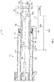
- FIGs. 1 and 2 illustrate a steering column assembly 100 according to one embodiment.
- the steering column assembly 100 broadly includes a jacket 110 and a bearing 115 rotatably supporting a steering shaft (or "spindle") 120 such that the spindle 120 at least partially extends inside the jacket 110.
- a steering shaft or "spindle”
- the spindle 120 has hollow outer tube 122 and a hollow inner tube 142 press-fit into the outer tube 122. While the outer and inner tubes 122, 142 may be constructed of any appropriate materials, it may be particularly desirable for the tubes 122, 142 to be constructed of metal (including metal alloys).
- the outer tube 122 has a lengthening section 123 and an attachment section 133, and the attachment section 133 in turn has a transition portion 135 and a connection portion 137.
- the lengthening section 123 adjoins the attachment section 133 at an end 135a of the transition portion 135, and the transition portion 135 is between the lengthening section 123 and the connection portion 137.
- the outer tube 122 terminates at an end 137b of the connection portion 137, and the connection portion 137 has an outer diameter 137a that is smaller than an outer diameter 123a of the lengthening section 123.
- the lengthening section 123 has first and second portions 124, 126, and the second portion 126 is between the first portion 124 and the transition portion 135.
- a length 126a of the second portion 126 is at least equal to (i.e., is not less than) a length 142a of the inner tube 142, and the length 126a of the second portion 126 is greater than a length 133a of the attachment section 133. In some embodiments, it may be particularly desirable for the length 126a of the second portion 126 to be at least three times the length 133a of the attachment section 133.
- At least part of the second portion 126 is cantilevered from the bearing 115, and in some embodiments it may be particularly desirable for a distance 118 between the bearing 115 and the end 137b of the connection portion 137 to be at least 70 mm and for the natural frequency of the connection portion 137 to be at least 55 Hz in a vertical direction and at least 57 Hz in a lateral direction. In some embodiments, it may be desirable for the natural frequency of the connection portion 137 to be at least 69 Hz in a vertical direction and at least 71 Hz in a lateral direction.
- the inner tube 142 does not extend into either the attachment section 133 or the first portion 124, and an end 142b of the inner tube 142 is adjacent the end 135a of the transition portion 135.
- An inner diameter 142c of the inner tube 142 is larger than an inner diameter 137c of the connection portion 137.
- the hollow outer tube 122 initially has generally uniform inner and outer diameters and terminates at the end 137b (from which the attachment section 133 extends).
- the hollow inner tube 142 initially has generally uniform inner and outer diameters, with the outer diameter of the inner tube being larger than the inner diameter of the outer tube.
- the inner tube 142 is press-fit entirely into the outer tube 122 with a longitudinal axis 149 of the inner tube 142 being coaxial with a longitudinal axis 129 of the outer tube 122.
- the inner tube 142 is sufficiently press-fit into the outer tube 122 such that the attachment section 133 is free of the inner tube 142 and the end 142b of the inner tube 142 is adjacent the attachment section 133.
- the inner tube 142 may be press-fit into the outer tube 122 by being inserted through the end 137b and the attachment section 133.
- the transition portion 135 and the connection portion 137 are formed only in the attachment section 133.
- the transition portion 135 and the connection portion 137 may be hammer-formed or created in any other appropriate manner, whether now existing or later developed. It may be particularly desirable in some embodiments for the natural frequency of the connection portion 137 after the inner tube 142 is press-fit into the outer tube 122 and the transition and connection portions 135, 137 are formed to be at least 55 Hz in a vertical direction and at least 57 Hz in a lateral direction.
- connection portion 137 after the inner tube 142 is press-fit into the outer tube 122 and the transition and connection portions 135, 137 are formed to be at least 69 Hz in a vertical direction and at least 71 Hz in a lateral direction.
- the outer tube 122 may be coupled with an inner shaft for torque transmitting, which is connectable with an input shaft of a steering gear, and a universal joint may be arranged between the inner shaft and the input shaft of the steering gear.
- the outer tube 122 and the inner shaft are telescopic to each other.
Landscapes
- Engineering & Computer Science (AREA)
- Mechanical Engineering (AREA)
- Chemical & Material Sciences (AREA)
- Combustion & Propulsion (AREA)
- Transportation (AREA)
- Steering Controls (AREA)
- Shafts, Cranks, Connecting Bars, And Related Bearings (AREA)
Claims (20)
- Lenkspindel (120), umfassend:ein hohles äußeres Rohr (122), das einen Verlängerungsbereich (123) und einen Befestigungsbereich (133) aufweist, wobei der Befestigungsbereich (133) einen Übergangsabschnitt (135) und einen Verbindungsabschnitt (137) aufweist, wobei der Verlängerungsbereich (123) an einem Ende (135a) des Übergangsabschnitts (135) an den Befestigungsbereich (133) angrenzt, wobei sich der Übergangsabschnitt (135) zwischen dem Verlängerungsbereich (123) und dem Verbindungsabschnitt (137) befindet, wobei ein Außendurchmesser (137a) des Verbindungsabschnitts (137) kleiner als ein Außendurchmesser (123a) des Verlängerungsbereichs (123) ist, wobei der Verlängerungsbereich (123) erste und zweite Abschnitte (124, 126) aufweist, wobei sich der zweite Abschnitt (126) zwischen dem ersten Abschnitt (124) und dem Übergangsabschnitt (135) befindet, wobei das äußere Rohr (122) an einem Ende (137b) des Verbindungsabschnitts (137) endet; undein hohles inneres Rohr (142), das in das äußere Rohr (122) pressgepasst ist, wobei ein Ende (142b) des inneren Rohrs (142) an das Ende (135a) des Übergangsabschnitts (135) angrenzt, wobei sich das innere Rohr (142) nicht in den Befestigungsbereich (133) erstreckt, wobei sich das innere Rohr (142) nicht in den ersten Abschnitt (124) erstreckt, wobei eine Länge (126a) des zweiten Abschnitts (126) mindestens gleich einer Länge (142a) des inneren Rohrs (142) ist.
- Lenkspindel nach Anspruch 1, wobei eine Länge (126a) des zweiten Abschnitts (126) größer als eine Länge (133a) des Befestigungsbereichs (133) ist.
- Lenkspindel nach Anspruch 2, wobei eine Länge (126a) des zweiten Abschnitts (126) mindestens dreimal eine Länge (133a) des Befestigungsbereichs (133) ist.
- Lenkspindel nach Anspruch 1, wobei ein Innendurchmesser (142c) des inneren Rohrs (142) größer als ein Innendurchmesser (137c) des Verbindungsabschnitts (137) ist.
- Lenkspindel nach Anspruch 1, wobei das äußere Rohr (122) aus Metall hergestellt ist und das innere Rohr (142) aus Metall hergestellt ist.
- Lenkspindel nach Anspruch 1, wobei die Eigenfrequenz des Verbindungsabschnitts (137) mindestens 55 Hz in einer vertikalen Richtung und mindestens 57 Hz in einer lateralen Richtung ist.
- Lenkspindel nach Anspruch 1, wobei die Eigenfrequenz des Verbindungsabschnitts (137) mindestens 69 Hz in einer vertikalen Richtung und mindestens 71 Hz in einer lateralen Richtung ist.
- Lenksäulenbaugruppe (100), umfassend:einen Mantel (110);ein Lager (115);eine Lenkspindel (120), die durch das Lager (115) drehbar gelagert ist und sich zumindest teilweise in den Mantel (110) erstreckt, wobei die Lenkspindel (120) umfasst:ein hohles äußeres Rohr (122), das einen Verlängerungsbereich (123) und einen Befestigungsbereich (133) aufweist, wobei der Befestigungsbereich (133) einen Übergangsabschnitt (135) und einen Verbindungsabschnitt (137) aufweist, wobei der Verlängerungsbereich (123) an einem Ende (135a) des Übergangsabschnitts (135) an den Befestigungsbereich (133) angrenzt, wobei sich der Übergangsabschnitt (135) zwischen dem Verlängerungsbereich (123) und dem Verbindungsabschnitt (137) befindet, wobei ein Außendurchmesser (137a) des Verbindungsabschnitts (137) kleiner als ein Außendurchmesser (123a) des Verlängerungsbereichs (123) ist, wobei der Verlängerungsbereich (123) erste und zweite Abschnitte (124, 126) aufweist, wobei sich der zweite Abschnitt (126) zwischen dem ersten Abschnitt (124) und dem Übergangsabschnitt (135) befindet, wobei das äußere Rohr (122) an einem Ende (137b) des Verbindungsabschnitts (137) endet; undein hohles inneres Rohr (142), das in das äußere Rohr (122) pressgepasst ist, wobei ein Ende (142a) des inneren Rohrs (142) an das Ende (135a) des Übergangsabschnitts (135) angrenzt, wobei sich das innere Rohr (142) nicht in den Befestigungsbereich (133) erstreckt, wobei sich das innere Rohr (142) nicht in den ersten Abschnitt (124) erstreckt, wobei eine Länge (126a) des zweiten Abschnitts (126) mindestens gleich einer Länge (142a) des inneren Rohrs (142) ist.
- Lenksäulenbaugruppe nach Anspruch 8, wobei:zumindest ein Teil des zweiten Abschnitts (126) von dem Lager (115) auskragt; undein Abstand (118) zwischen dem Lager (115) und dem Ende (137b) des Verbindungsabschnitts (137) mindestens 70 mm ist.
- Lenksäulenbaugruppe nach Anspruch 9, wobei die Eigenfrequenz des Verbindungsabschnitts (137) mindestens 55 Hz in einer vertikalen Richtung und mindestens 57 Hz in einer lateralen Richtung ist.
- Lenksäulenbaugruppe nach Anspruch 10, wobei:eine Länge (126a) des zweiten Abschnitts (126) größer als eine Länge (133a) des Befestigungsbereichs (133) ist; undein Innendurchmesser (142a) des inneren Rohrs (142) größer als ein Innendurchmesser (137c) des Verbindungsabschnitts (137) ist.
- Lenksäulenbaugruppe nach Anspruch 8, wobei:eine Länge (126a) des zweiten Abschnitts (126) größer als eine Länge (133a) des Befestigungsbereichs (133) ist; undein Innendurchmesser (142a) des inneren Rohrs (142) größer als ein Innendurchmesser (137c) des Verbindungsabschnitts (137) ist.
- Lenksäulenbaugruppe nach Anspruch 8, wobei das äußere Rohr (122) aus Metall hergestellt ist und das innere Rohr (142) aus Metall hergestellt ist.
- Lenksäulenbaugruppe nach Anspruch 8, wobei die Eigenfrequenz des Verbindungsabschnitts (137) mindestens 55 Hz in einer vertikalen Richtung und mindestens 57 Hz in einer lateralen Richtung ist.
- Lenksäulenbaugruppe nach Anspruch 8, wobei die Eigenfrequenz des Verbindungsabschnitts (137) mindestens 69 Hz in einer vertikalen Richtung und mindestens 71 Hz in einer lateralen Richtung ist.
- Verfahren zum Herstellen einer Lenkspindel (120), umfassend:Bereitstellen eines hohlen äußeren Rohrs (122), das einen gleichmäßigen Innendurchmesser und eine Längsachse (129) aufweist, wobei das äußere Rohr (122) an einem Ende (137b) endet, wobei sich ein Befestigungsbereich (133) des äußeren Rohrs (122) von dem Ende (137b) des äußeren Rohrs (122) erstreckt;Bereitstellen eines hohlen inneren Rohrs (142), das einen gleichmäßigen Außendurchmesser und eine Längsachse (149) aufweist, wobei der Außendurchmesser des inneren Rohrs (142) größer als der Innendurchmesser des äußeren Rohrs (122) ist;Presspassen des inneren Rohrs (142) vollständig in das äußere Rohr (122), wobei die Längsachse (149) des inneren Rohrs (142) koaxial mit der Längs(129)-Achse des äußeren Rohrs (122) ist, wobei der Befestigungsbereich (133) frei von dem inneren Rohr (142) ist, wobei ein Ende (142b) des inneren Rohrs (142) an den Befestigungsbereich (133) angrenzt; undFormen eines Übergangsabschnitts (135) und eines Verbindungsabschnitts (137) nur in dem Befestigungsbereich (133).
- Verfahren nach Anspruch 16, wobei die Eigenfrequenz des Verbindungsabschnitts (137), nachdem das innere Rohr (142) in das äußere Rohr (122) pressgepasst ist, mindestens 69 Hz in einer vertikalen Richtung und mindestens 71 Hz in einer lateralen Richtung ist.
- Verfahren nach Anspruch 16, wobei das hohle äußere (122) Rohr einen Verlängerungsbereich (123) und den Befestigungsbereich (133) aufweist, wobei der Verlängerungsbereich (123) an einem Ende (135a) des Übergangsabschnitts (135) an den Befestigungsbereich (133) angrenzt, wobei sich der Übergangsabschnitt (135) zwischen dem Verlängerungsbereich (123) und dem Verbindungsabschnitt (137) befindet, wobei ein Außendurchmesser (137a) des Verbindungsabschnitts (137) kleiner als ein Außendurchmesser (123a) des Verlängerungsbereichs (123) ist, wobei der Verlängerungsbereich (123) erste und zweite Abschnitte (124, 126) aufweist, wobei sich der zweite Abschnitt (126) zwischen dem ersten Abschnitt (124) und dem Übergangsabschnitt (135) befindet, wobei das äußere Rohr (122) an einem Ende (137b) des Verbindungsabschnitts (137) endet, wobei eine Länge (126a) des zweiten Abschnitts (126) größer als eine Länge (133a) des Befestigungsbereichs (133) ist.
- Verfahren nach Anspruch 16, wobei der Schritt des Presspassens Presspassen des inneren Rohrs (142) in das äußere Rohr (122) durch das äußere Rohrende (137b) und den Befestigungsbereich (133) umfasst.
- Verfahren nach Anspruch 16, wobei der Schritt des Formens Hammerformen umfasst.
Applications Claiming Priority (2)
| Application Number | Priority Date | Filing Date | Title |
|---|---|---|---|
| US15/833,585 US10532761B2 (en) | 2017-12-06 | 2017-12-06 | Spindle and steering column assembly having same |
| PCT/EP2018/083361 WO2019110514A1 (en) | 2017-12-06 | 2018-12-03 | Spindle and steering column assembly having same |
Publications (2)
| Publication Number | Publication Date |
|---|---|
| EP3720754A1 EP3720754A1 (de) | 2020-10-14 |
| EP3720754B1 true EP3720754B1 (de) | 2022-04-20 |
Family
ID=64901482
Family Applications (1)
| Application Number | Title | Priority Date | Filing Date |
|---|---|---|---|
| EP18826968.2A Active EP3720754B1 (de) | 2017-12-06 | 2018-12-03 | Spindel und lenksäulenanordnung damit |
Country Status (4)
| Country | Link |
|---|---|
| US (2) | US10532761B2 (de) |
| EP (1) | EP3720754B1 (de) |
| CN (1) | CN111491849B (de) |
| WO (1) | WO2019110514A1 (de) |
Family Cites Families (37)
| Publication number | Priority date | Publication date | Assignee | Title |
|---|---|---|---|---|
| US1555214A (en) * | 1924-02-09 | 1925-09-29 | Cleveland Graphite Bronze Co | Bearing |
| US4304147A (en) * | 1980-01-23 | 1981-12-08 | The Torrington Company | Steering column |
| DE3536285C1 (en) * | 1985-10-11 | 1987-04-30 | Lemfoerder Metallwaren Ag | Adjustable steering column for motor vehicles - has support bearing with hinged connectors, longitudinally adjustable, with top column spindle part carrying support bearing |
| DE4030405C2 (de) * | 1990-09-26 | 1994-01-27 | Porsche Ag | Verstellbare Sicherheitslenksäule für ein Kraftfahrzeug |
| ATE133118T1 (de) * | 1992-06-03 | 1996-02-15 | Reiche & Co | Kraftfahrzeuglenksäule |
| US5590565A (en) * | 1995-02-08 | 1997-01-07 | General Motors Corporation | Motor vehicle steering column |
| US5722300A (en) * | 1996-08-16 | 1998-03-03 | General Motors Corporation | Motor vehicle steering column |
| JP2001151123A (ja) | 1999-11-22 | 2001-06-05 | Nsk Ltd | 車両用電動パワーステアリング装置 |
| DE10031902B4 (de) * | 2000-06-30 | 2005-06-16 | Daimlerchrysler Ag | Überlastsicherung und ein Verfahren zu deren Herstellung |
| DE10055608A1 (de) * | 2000-11-09 | 2002-05-23 | Daimler Chrysler Ag | Lenkspindelanordnung und ein Verfahren zu deren Herstellung |
| JP3886766B2 (ja) * | 2001-01-11 | 2007-02-28 | 富士機工株式会社 | チルト・テレスコピック式ステアリングコラム装置 |
| JP4571341B2 (ja) * | 2001-06-18 | 2010-10-27 | 水島プレス工業株式会社 | ステアリング装置のダンパ機構 |
| WO2004108502A1 (ja) * | 2003-06-03 | 2004-12-16 | Nsk Ltd. | 車両用衝撃吸収式ステアリングコラム装置 |
| GB0328695D0 (en) * | 2003-12-11 | 2004-01-14 | Trw Lucas Varity Electric | A steering column assembly |
| US7267370B2 (en) | 2004-03-11 | 2007-09-11 | Delphi Technologies, Inc. | Frequency and stiffness enhancement mechanization |
| JP2007030527A (ja) * | 2005-02-17 | 2007-02-08 | Nsk Ltd | ステアリングホイールの電動式位置調節装置 |
| JP4529796B2 (ja) * | 2005-05-26 | 2010-08-25 | アイシン精機株式会社 | 衝撃吸収式ステアリング装置 |
| US8127639B2 (en) | 2005-08-16 | 2012-03-06 | Steering Solutions IP Holding Company, a Delaware corporation | Sleeve bearing for collapsible steering column |
| GB0525850D0 (en) * | 2005-09-01 | 2006-02-01 | Trw Lucasvarity Electric Steer | A Steering Column Assembly |
| US7497470B2 (en) * | 2005-11-21 | 2009-03-03 | Delphi Technologies, Inc. | Energy absorbing apparatus |
| JP4868213B2 (ja) * | 2005-12-21 | 2012-02-01 | アイシン精機株式会社 | エネルギー吸収ステアリングコラム |
| DE102006010228B3 (de) * | 2006-03-02 | 2007-11-22 | Thyssenkrupp Presta Ag | Verfahren zur Herstellung eines Lenkspindelteils |
| US20070245845A1 (en) * | 2006-04-20 | 2007-10-25 | Ridgway Jason R | Steering column assembly for a vehicle |
| US8627742B2 (en) * | 2008-04-04 | 2014-01-14 | Steering Solutions Ip Holding Corporation | Steering column assembly with shearable jacket connector |
| GB0808798D0 (en) * | 2008-05-15 | 2008-06-18 | Trw Ltd | Adjustable steering column assembly |
| JP5369537B2 (ja) * | 2008-08-08 | 2013-12-18 | アイシン精機株式会社 | エネルギー吸収ステアリングコラム |
| DE102009038316A1 (de) | 2009-08-21 | 2011-02-24 | Thyssenkrupp Presta Ag | Verfahren zur Herstellung eines einen Abschnitt einer Lenkspindel bildenden Lenkspindelteils |
| JP5626342B2 (ja) * | 2011-04-04 | 2014-11-19 | 日本精工株式会社 | ステアリング装置 |
| JP6212915B2 (ja) * | 2013-04-10 | 2017-10-18 | アイシン精機株式会社 | 車両のステアリング装置 |
| DE102013009497A1 (de) | 2013-06-05 | 2014-12-11 | Daimler Ag | Teleskopierbare Antriebswelle |
| GB201323068D0 (en) * | 2013-12-27 | 2014-02-12 | Trw Ltd | Steering column Assembley |
| DE102014107292B3 (de) * | 2014-05-23 | 2015-05-21 | Thyssenkrupp Presta Ag | Lenksäule für ein Kraftfahrzeug |
| GB201420942D0 (en) * | 2014-11-25 | 2015-01-07 | Trw Ltd | Improvements to steering column assemblies |
| DE102016205378B3 (de) * | 2016-03-31 | 2017-05-11 | Thyssenkrupp Ag | Lenksäule für ein Kraftfahrzeug |
| CN105835940B (zh) * | 2016-03-31 | 2019-02-19 | 广州汽车集团股份有限公司 | 转向管柱及汽车转向系统 |
| JP6621359B2 (ja) * | 2016-03-31 | 2019-12-18 | 富士機工株式会社 | ステアリングコラム装置 |
| DE102016214163A1 (de) * | 2016-08-01 | 2016-10-13 | Thyssenkrupp Ag | Verfahren zur Herstellung eines Lenkspindelteils und Lenkspindel für ein Kraftfahrzeug |
-
2017
- 2017-12-06 US US15/833,585 patent/US10532761B2/en active Active
-
2018
- 2018-12-03 WO PCT/EP2018/083361 patent/WO2019110514A1/en not_active Ceased
- 2018-12-03 CN CN201880078463.6A patent/CN111491849B/zh active Active
- 2018-12-03 EP EP18826968.2A patent/EP3720754B1/de active Active
-
2019
- 2019-12-09 US US16/707,007 patent/US11091187B2/en active Active
Also Published As
| Publication number | Publication date |
|---|---|
| US20200114947A1 (en) | 2020-04-16 |
| EP3720754A1 (de) | 2020-10-14 |
| US11091187B2 (en) | 2021-08-17 |
| WO2019110514A1 (en) | 2019-06-13 |
| CN111491849B (zh) | 2022-07-15 |
| US10532761B2 (en) | 2020-01-14 |
| US20190168796A1 (en) | 2019-06-06 |
| CN111491849A (zh) | 2020-08-04 |
Similar Documents
| Publication | Publication Date | Title |
|---|---|---|
| EP2917594B1 (de) | Hydrogeformte antriebswellenröhre mit sekundärstruktur | |
| EP1586794A2 (de) | Differential mit Ritzellager unterstützt vom Eingangskreuzgelenk | |
| JP2000035049A (ja) | ユニバーサルジョイント | |
| CN101394953B (zh) | 用于加工转向轴部件的方法 | |
| JP2012067796A (ja) | ウォーム減速機 | |
| US20180304422A1 (en) | Method for manufacturing rack bar | |
| US20030083171A1 (en) | Differential with pinion bearings supported on input yoke | |
| US11091187B2 (en) | Spindle and steering column assembly having same | |
| US8986126B2 (en) | Cross universal joint and manufacturing method thereof | |
| DE102018001449A1 (de) | Leichtbau - Antriebswelle | |
| JP2019044945A (ja) | トルク伝達軸 | |
| JP5159527B2 (ja) | ステアリングシャフトのロアーシャフト用連結シャフト部材 | |
| DE602004002736T2 (de) | Antriebswellenanordnung mit Dämpfer | |
| CN216546355U (zh) | 一种汽车转向器的中间轴结构 | |
| JP2566715B2 (ja) | ステアリングロッド及びその製造方法 | |
| DE3031039C2 (de) | Tragrohr für eine Trieb- und Fahrwerksanordnung für Kraftfahrzeuge | |
| JP2016052895A (ja) | ステアリング装置 | |
| JP2007320407A (ja) | 中空スタビライザ | |
| CN101674904B (zh) | 车辆用短轴的制造方法 | |
| JP4968100B2 (ja) | 十字軸自在継手 | |
| JP5742982B2 (ja) | シャフトと自在継手のヨークとの結合部及びその製造方法 | |
| KR20200009581A (ko) | 자동차용 유니버설 조인트의 샤프트조인트 및 그 제조방법 | |
| JP2017003085A (ja) | 自在継手および該自在継手を備えたステアリング装置 | |
| KR20250166682A (ko) | 등속 조인트 외륜 복합 중공 부재 스플라인의 전조 제조 방법 | |
| WO2016199807A1 (ja) | 自在継手用ヨーク |
Legal Events
| Date | Code | Title | Description |
|---|---|---|---|
| STAA | Information on the status of an ep patent application or granted ep patent |
Free format text: STATUS: UNKNOWN |
|
| STAA | Information on the status of an ep patent application or granted ep patent |
Free format text: STATUS: THE INTERNATIONAL PUBLICATION HAS BEEN MADE |
|
| PUAI | Public reference made under article 153(3) epc to a published international application that has entered the european phase |
Free format text: ORIGINAL CODE: 0009012 |
|
| STAA | Information on the status of an ep patent application or granted ep patent |
Free format text: STATUS: REQUEST FOR EXAMINATION WAS MADE |
|
| 17P | Request for examination filed |
Effective date: 20200706 |
|
| AK | Designated contracting states |
Kind code of ref document: A1 Designated state(s): AL AT BE BG CH CY CZ DE DK EE ES FI FR GB GR HR HU IE IS IT LI LT LU LV MC MK MT NL NO PL PT RO RS SE SI SK SM TR |
|
| AX | Request for extension of the european patent |
Extension state: BA ME |
|
| RIN1 | Information on inventor provided before grant (corrected) |
Inventor name: PICHONNAT, CHRISTIAN Inventor name: GEISELBERGER, THOMAS Inventor name: YOHO, JUSTIN |
|
| DAV | Request for validation of the european patent (deleted) | ||
| DAX | Request for extension of the european patent (deleted) | ||
| RIN1 | Information on inventor provided before grant (corrected) |
Inventor name: YOHO, JUSTIN Inventor name: PICHONNAT, CHRISTIAN Inventor name: GEISELBERGER, THOMAS |
|
| GRAP | Despatch of communication of intention to grant a patent |
Free format text: ORIGINAL CODE: EPIDOSNIGR1 |
|
| STAA | Information on the status of an ep patent application or granted ep patent |
Free format text: STATUS: GRANT OF PATENT IS INTENDED |
|
| INTG | Intention to grant announced |
Effective date: 20211129 |
|
| GRAS | Grant fee paid |
Free format text: ORIGINAL CODE: EPIDOSNIGR3 |
|
| GRAA | (expected) grant |
Free format text: ORIGINAL CODE: 0009210 |
|
| STAA | Information on the status of an ep patent application or granted ep patent |
Free format text: STATUS: THE PATENT HAS BEEN GRANTED |
|
| AK | Designated contracting states |
Kind code of ref document: B1 Designated state(s): AL AT BE BG CH CY CZ DE DK EE ES FI FR GB GR HR HU IE IS IT LI LT LU LV MC MK MT NL NO PL PT RO RS SE SI SK SM TR |
|
| REG | Reference to a national code |
Ref country code: GB Ref legal event code: FG4D |
|
| REG | Reference to a national code |
Ref country code: CH Ref legal event code: EP |
|
| REG | Reference to a national code |
Ref country code: IE Ref legal event code: FG4D |
|
| REG | Reference to a national code |
Ref country code: DE Ref legal event code: R096 Ref document number: 602018034273 Country of ref document: DE |
|
| REG | Reference to a national code |
Ref country code: AT Ref legal event code: REF Ref document number: 1484966 Country of ref document: AT Kind code of ref document: T Effective date: 20220515 |
|
| REG | Reference to a national code |
Ref country code: LT Ref legal event code: MG9D |
|
| REG | Reference to a national code |
Ref country code: NL Ref legal event code: MP Effective date: 20220420 |
|
| REG | Reference to a national code |
Ref country code: DE Ref legal event code: R084 Ref document number: 602018034273 Country of ref document: DE |
|
| REG | Reference to a national code |
Ref country code: AT Ref legal event code: MK05 Ref document number: 1484966 Country of ref document: AT Kind code of ref document: T Effective date: 20220420 |
|
| RAP4 | Party data changed (patent owner data changed or rights of a patent transferred) |
Owner name: THYSSENKRUPP AG Owner name: THYSSENKRUPP PRESTA AG |
|
| PG25 | Lapsed in a contracting state [announced via postgrant information from national office to epo] |
Ref country code: NL Free format text: LAPSE BECAUSE OF FAILURE TO SUBMIT A TRANSLATION OF THE DESCRIPTION OR TO PAY THE FEE WITHIN THE PRESCRIBED TIME-LIMIT Effective date: 20220420 |
|
| PG25 | Lapsed in a contracting state [announced via postgrant information from national office to epo] |
Ref country code: SE Free format text: LAPSE BECAUSE OF FAILURE TO SUBMIT A TRANSLATION OF THE DESCRIPTION OR TO PAY THE FEE WITHIN THE PRESCRIBED TIME-LIMIT Effective date: 20220420 Ref country code: PT Free format text: LAPSE BECAUSE OF FAILURE TO SUBMIT A TRANSLATION OF THE DESCRIPTION OR TO PAY THE FEE WITHIN THE PRESCRIBED TIME-LIMIT Effective date: 20220822 Ref country code: NO Free format text: LAPSE BECAUSE OF FAILURE TO SUBMIT A TRANSLATION OF THE DESCRIPTION OR TO PAY THE FEE WITHIN THE PRESCRIBED TIME-LIMIT Effective date: 20220720 Ref country code: LT Free format text: LAPSE BECAUSE OF FAILURE TO SUBMIT A TRANSLATION OF THE DESCRIPTION OR TO PAY THE FEE WITHIN THE PRESCRIBED TIME-LIMIT Effective date: 20220420 Ref country code: HR Free format text: LAPSE BECAUSE OF FAILURE TO SUBMIT A TRANSLATION OF THE DESCRIPTION OR TO PAY THE FEE WITHIN THE PRESCRIBED TIME-LIMIT Effective date: 20220420 Ref country code: GR Free format text: LAPSE BECAUSE OF FAILURE TO SUBMIT A TRANSLATION OF THE DESCRIPTION OR TO PAY THE FEE WITHIN THE PRESCRIBED TIME-LIMIT Effective date: 20220721 Ref country code: FI Free format text: LAPSE BECAUSE OF FAILURE TO SUBMIT A TRANSLATION OF THE DESCRIPTION OR TO PAY THE FEE WITHIN THE PRESCRIBED TIME-LIMIT Effective date: 20220420 Ref country code: ES Free format text: LAPSE BECAUSE OF FAILURE TO SUBMIT A TRANSLATION OF THE DESCRIPTION OR TO PAY THE FEE WITHIN THE PRESCRIBED TIME-LIMIT Effective date: 20220420 Ref country code: BG Free format text: LAPSE BECAUSE OF FAILURE TO SUBMIT A TRANSLATION OF THE DESCRIPTION OR TO PAY THE FEE WITHIN THE PRESCRIBED TIME-LIMIT Effective date: 20220720 Ref country code: AT Free format text: LAPSE BECAUSE OF FAILURE TO SUBMIT A TRANSLATION OF THE DESCRIPTION OR TO PAY THE FEE WITHIN THE PRESCRIBED TIME-LIMIT Effective date: 20220420 |
|
| PG25 | Lapsed in a contracting state [announced via postgrant information from national office to epo] |
Ref country code: RS Free format text: LAPSE BECAUSE OF FAILURE TO SUBMIT A TRANSLATION OF THE DESCRIPTION OR TO PAY THE FEE WITHIN THE PRESCRIBED TIME-LIMIT Effective date: 20220420 Ref country code: PL Free format text: LAPSE BECAUSE OF FAILURE TO SUBMIT A TRANSLATION OF THE DESCRIPTION OR TO PAY THE FEE WITHIN THE PRESCRIBED TIME-LIMIT Effective date: 20220420 Ref country code: LV Free format text: LAPSE BECAUSE OF FAILURE TO SUBMIT A TRANSLATION OF THE DESCRIPTION OR TO PAY THE FEE WITHIN THE PRESCRIBED TIME-LIMIT Effective date: 20220420 Ref country code: IS Free format text: LAPSE BECAUSE OF FAILURE TO SUBMIT A TRANSLATION OF THE DESCRIPTION OR TO PAY THE FEE WITHIN THE PRESCRIBED TIME-LIMIT Effective date: 20220820 |
|
| REG | Reference to a national code |
Ref country code: DE Ref legal event code: R097 Ref document number: 602018034273 Country of ref document: DE |
|
| PG25 | Lapsed in a contracting state [announced via postgrant information from national office to epo] |
Ref country code: SM Free format text: LAPSE BECAUSE OF FAILURE TO SUBMIT A TRANSLATION OF THE DESCRIPTION OR TO PAY THE FEE WITHIN THE PRESCRIBED TIME-LIMIT Effective date: 20220420 Ref country code: SK Free format text: LAPSE BECAUSE OF FAILURE TO SUBMIT A TRANSLATION OF THE DESCRIPTION OR TO PAY THE FEE WITHIN THE PRESCRIBED TIME-LIMIT Effective date: 20220420 Ref country code: RO Free format text: LAPSE BECAUSE OF FAILURE TO SUBMIT A TRANSLATION OF THE DESCRIPTION OR TO PAY THE FEE WITHIN THE PRESCRIBED TIME-LIMIT Effective date: 20220420 Ref country code: EE Free format text: LAPSE BECAUSE OF FAILURE TO SUBMIT A TRANSLATION OF THE DESCRIPTION OR TO PAY THE FEE WITHIN THE PRESCRIBED TIME-LIMIT Effective date: 20220420 Ref country code: DK Free format text: LAPSE BECAUSE OF FAILURE TO SUBMIT A TRANSLATION OF THE DESCRIPTION OR TO PAY THE FEE WITHIN THE PRESCRIBED TIME-LIMIT Effective date: 20220420 Ref country code: CZ Free format text: LAPSE BECAUSE OF FAILURE TO SUBMIT A TRANSLATION OF THE DESCRIPTION OR TO PAY THE FEE WITHIN THE PRESCRIBED TIME-LIMIT Effective date: 20220420 |
|
| PLBE | No opposition filed within time limit |
Free format text: ORIGINAL CODE: 0009261 |
|
| STAA | Information on the status of an ep patent application or granted ep patent |
Free format text: STATUS: NO OPPOSITION FILED WITHIN TIME LIMIT |
|
| 26N | No opposition filed |
Effective date: 20230123 |
|
| PG25 | Lapsed in a contracting state [announced via postgrant information from national office to epo] |
Ref country code: AL Free format text: LAPSE BECAUSE OF FAILURE TO SUBMIT A TRANSLATION OF THE DESCRIPTION OR TO PAY THE FEE WITHIN THE PRESCRIBED TIME-LIMIT Effective date: 20220420 |
|
| PG25 | Lapsed in a contracting state [announced via postgrant information from national office to epo] |
Ref country code: SI Free format text: LAPSE BECAUSE OF FAILURE TO SUBMIT A TRANSLATION OF THE DESCRIPTION OR TO PAY THE FEE WITHIN THE PRESCRIBED TIME-LIMIT Effective date: 20220420 |
|
| REG | Reference to a national code |
Ref country code: CH Ref legal event code: PL |
|
| REG | Reference to a national code |
Ref country code: BE Ref legal event code: MM Effective date: 20221231 |
|
| PG25 | Lapsed in a contracting state [announced via postgrant information from national office to epo] |
Ref country code: LU Free format text: LAPSE BECAUSE OF NON-PAYMENT OF DUE FEES Effective date: 20221203 |
|
| PG25 | Lapsed in a contracting state [announced via postgrant information from national office to epo] |
Ref country code: LI Free format text: LAPSE BECAUSE OF NON-PAYMENT OF DUE FEES Effective date: 20221231 Ref country code: IE Free format text: LAPSE BECAUSE OF NON-PAYMENT OF DUE FEES Effective date: 20221203 Ref country code: CH Free format text: LAPSE BECAUSE OF NON-PAYMENT OF DUE FEES Effective date: 20221231 |
|
| PG25 | Lapsed in a contracting state [announced via postgrant information from national office to epo] |
Ref country code: BE Free format text: LAPSE BECAUSE OF NON-PAYMENT OF DUE FEES Effective date: 20221231 |
|
| PG25 | Lapsed in a contracting state [announced via postgrant information from national office to epo] |
Ref country code: IT Free format text: LAPSE BECAUSE OF FAILURE TO SUBMIT A TRANSLATION OF THE DESCRIPTION OR TO PAY THE FEE WITHIN THE PRESCRIBED TIME-LIMIT Effective date: 20220420 |
|
| PG25 | Lapsed in a contracting state [announced via postgrant information from national office to epo] |
Ref country code: CY Free format text: LAPSE BECAUSE OF FAILURE TO SUBMIT A TRANSLATION OF THE DESCRIPTION OR TO PAY THE FEE WITHIN THE PRESCRIBED TIME-LIMIT Effective date: 20220420 |
|
| PG25 | Lapsed in a contracting state [announced via postgrant information from national office to epo] |
Ref country code: MK Free format text: LAPSE BECAUSE OF FAILURE TO SUBMIT A TRANSLATION OF THE DESCRIPTION OR TO PAY THE FEE WITHIN THE PRESCRIBED TIME-LIMIT Effective date: 20220420 Ref country code: HU Free format text: LAPSE BECAUSE OF FAILURE TO SUBMIT A TRANSLATION OF THE DESCRIPTION OR TO PAY THE FEE WITHIN THE PRESCRIBED TIME-LIMIT; INVALID AB INITIO Effective date: 20181203 |
|
| PG25 | Lapsed in a contracting state [announced via postgrant information from national office to epo] |
Ref country code: MC Free format text: LAPSE BECAUSE OF FAILURE TO SUBMIT A TRANSLATION OF THE DESCRIPTION OR TO PAY THE FEE WITHIN THE PRESCRIBED TIME-LIMIT Effective date: 20220420 |
|
| PG25 | Lapsed in a contracting state [announced via postgrant information from national office to epo] |
Ref country code: TR Free format text: LAPSE BECAUSE OF FAILURE TO SUBMIT A TRANSLATION OF THE DESCRIPTION OR TO PAY THE FEE WITHIN THE PRESCRIBED TIME-LIMIT Effective date: 20220420 Ref country code: MC Free format text: LAPSE BECAUSE OF FAILURE TO SUBMIT A TRANSLATION OF THE DESCRIPTION OR TO PAY THE FEE WITHIN THE PRESCRIBED TIME-LIMIT Effective date: 20220420 |
|
| PG25 | Lapsed in a contracting state [announced via postgrant information from national office to epo] |
Ref country code: MT Free format text: LAPSE BECAUSE OF FAILURE TO SUBMIT A TRANSLATION OF THE DESCRIPTION OR TO PAY THE FEE WITHIN THE PRESCRIBED TIME-LIMIT Effective date: 20220420 |
|
| PG25 | Lapsed in a contracting state [announced via postgrant information from national office to epo] |
Ref country code: BG Free format text: LAPSE BECAUSE OF FAILURE TO SUBMIT A TRANSLATION OF THE DESCRIPTION OR TO PAY THE FEE WITHIN THE PRESCRIBED TIME-LIMIT Effective date: 20220420 |
|
| PG25 | Lapsed in a contracting state [announced via postgrant information from national office to epo] |
Ref country code: BG Free format text: LAPSE BECAUSE OF FAILURE TO SUBMIT A TRANSLATION OF THE DESCRIPTION OR TO PAY THE FEE WITHIN THE PRESCRIBED TIME-LIMIT Effective date: 20220420 |
|
| PGFP | Annual fee paid to national office [announced via postgrant information from national office to epo] |
Ref country code: DE Payment date: 20251211 Year of fee payment: 8 |
|
| PGFP | Annual fee paid to national office [announced via postgrant information from national office to epo] |
Ref country code: GB Payment date: 20251219 Year of fee payment: 8 |
|
| PGFP | Annual fee paid to national office [announced via postgrant information from national office to epo] |
Ref country code: FR Payment date: 20251229 Year of fee payment: 8 |