EP3719523A1 - Passive shim tray for magnetic resonance examination system - Google Patents
Passive shim tray for magnetic resonance examination system Download PDFInfo
- Publication number
- EP3719523A1 EP3719523A1 EP19166707.0A EP19166707A EP3719523A1 EP 3719523 A1 EP3719523 A1 EP 3719523A1 EP 19166707 A EP19166707 A EP 19166707A EP 3719523 A1 EP3719523 A1 EP 3719523A1
- Authority
- EP
- European Patent Office
- Prior art keywords
- shim
- side walls
- tray
- elements
- channel
- Prior art date
- Legal status (The legal status is an assumption and is not a legal conclusion. Google has not performed a legal analysis and makes no representation as to the accuracy of the status listed.)
- Withdrawn
Links
- 230000005291 magnetic effect Effects 0.000 title abstract description 24
- 230000037431 insertion Effects 0.000 claims abstract description 28
- 238000003780 insertion Methods 0.000 claims abstract description 28
- 230000005294 ferromagnetic effect Effects 0.000 description 4
- 238000004519 manufacturing process Methods 0.000 description 4
- XEEYBQQBJWHFJM-UHFFFAOYSA-N Iron Chemical compound [Fe] XEEYBQQBJWHFJM-UHFFFAOYSA-N 0.000 description 2
- 229910000831 Steel Inorganic materials 0.000 description 1
- 238000010276 construction Methods 0.000 description 1
- 230000007797 corrosion Effects 0.000 description 1
- 238000005260 corrosion Methods 0.000 description 1
- 230000001419 dependent effect Effects 0.000 description 1
- 238000003384 imaging method Methods 0.000 description 1
- 238000001746 injection moulding Methods 0.000 description 1
- 229910052742 iron Inorganic materials 0.000 description 1
- 239000000696 magnetic material Substances 0.000 description 1
- 239000000243 solution Substances 0.000 description 1
- 238000004611 spectroscopical analysis Methods 0.000 description 1
- 239000010959 steel Substances 0.000 description 1
Images
Classifications
-
- G—PHYSICS
- G01—MEASURING; TESTING
- G01R—MEASURING ELECTRIC VARIABLES; MEASURING MAGNETIC VARIABLES
- G01R33/00—Arrangements or instruments for measuring magnetic variables
- G01R33/20—Arrangements or instruments for measuring magnetic variables involving magnetic resonance
- G01R33/28—Details of apparatus provided for in groups G01R33/44 - G01R33/64
- G01R33/38—Systems for generation, homogenisation or stabilisation of the main or gradient magnetic field
- G01R33/387—Compensation of inhomogeneities
- G01R33/3873—Compensation of inhomogeneities using ferromagnetic bodies ; Passive shimming
Definitions
- the invention pertains to a shim tray for a main magnet system of a magnetic resonance examination system.
- a spatially uniform strong main magnetic field is employed in the magnetic resonance examination system's examination region onto which temporary gradient magnetic field pulses are superposed.
- the spatially uninform main magnetic field causes a spatially homogeneous magnetic polarisation of the object to be examined (patient to be examined) and the temporary gradient magnetic field pulses provide for spatial encoding of the magnetic resonance signals.
- the main magnetic field may have a field strength of 1.5, 3.0, 7.0T or even higher.
- so-called ferromagnetic shim elements iron or steel
- ferromagnetic shim elements iron or steel
- a number of shim trays is arranged around the magnet's bore and each shim tray contains a number of shim pockets to hold a number of shim elements.
- the shim trays may slide longitudinally (along the direction of the main magnetic field) into their proper position so that the shim elements are correctly positioned).
- the US-patent application US2003/0214300 discloses a shim tray that is subdivided into the shim pockets in the axial direction that can be filled with shim laminae of magnetic material according the inhomogeneities of the magnetic field to be corrected.
- An object of the invention is to provide a shim tray that has a higher shim capacity as compared to the known shim tray.
- the shim tray comprising a plurality of shim pockets, of which an individual shim pocket has side walls forming an open channel and two opposite lateral side walls have insertion profiles to receive an end shim-element at least one at open channel's end.
- open channels form the individual shim pockets.
- Each of the shim pockets is covered at one or more of its channel ends by the end shim elements.
- the channels are open in that they may be freely accessible along the axis of the channel from one or both ends. Up to the top and/or bottom cover(s) such an individual channel may be filled with ferromagnetic end shim element(s) and ferromagnetic shim elements.
- the shim tray of the invention may also enable to adequately shim magnets that could not be properly shimmed with the conventional shim tray.
- the channel's opposite longitudinal side walls have insertion profiles, notably near the channel's end(s).
- the end shim elements are held mechanically in positon and can withstand the magnetic forces when the shim tray is slid in position. Note that, e.g. during mounting, the shim tray is moved in a region (outside of the examination region) where the main magnetic field may have strong inhomogeneities so that magnetic forces of varying strength and orientations will act on the shim elements of the shim tray while slid longitudinally into position.
- the end shim element(s) are shaped so that their sides precisely lodge in the insertion profiles and the end shim elements may be laterally slid into the insertion profiles.
- the insertion profiles are provided at both channel ends and end shim elements are located at both channel ends inserted in their insertion profile.
- insertion profiles may be provided at one channel end and at the opposite channel end a conventional cover closes the open channel.
- the channel is an open channel with a single sided opening that may be closed by the end shim element.
- the shim elements are polygon shaped and the orientation(s) of the insertion profiles matches with the polygon-shape to allow the polygon shaped shim elements to easily slide into the insertion profiles.
- a rectangular or square four-sided shape works well, is easy to manufacture and the insertion profiles are easy to match.
- a number of shim elements may be stacked into the channel having their normal along the channel's axis. These shim elements are held in place by the channel's side walls and the end shim elements.
- the end shim elements held in position in the insertion profiles hold the shim elements in the channel along the channel axis. In other words, the insertion profiles mechanically hold the end shim elements, which then hold the shim elements in the channel. While the end shim elements may be placed by sliding them laterally into the insertion profiles, the shim elements may be entered along the transverse direction into the shim pocket.
- the channel may be closed by laterally sliding in the end shim element at the top. Then the shim elements are secured between the end (top and bottom) shim elements, the latter being secured in the insertion profiles. Preferably, the end shim elements are flush with the top and bottom. This configuration maximises the available shim volume.
- the insertion profiles are longitudinal indents in the lateral side walls of the channel of the shim pocket.
- the insertion profiles are made as an integral part of the lateral side walls.
- the indents extend laterally along the lateral side walls. This is easy to manufacture.
- the opposite side walls are parallel, so as to fit rectangular end shim elements to be easily slid laterally into the insertion profiles.
- lateral side walls extend laterally between the longitudinal rails.
- the longitudinal rails match with shim channels in the magnet structure and allow the shim tray to easily slide into the shim channels of the magnet structure.
- the lateral side walls and the longitudinal rails form the lateral and longitudinal side walls, respectively of the individual channels. That is, the shim tray of the invention has parallel longitudinal rails that form the longitudinal side walls of each of the shim pockets.
- the longitudinal side walls of the each of the shim pockets are a part of one of the longitudinal rails. This construction renders the shim tray of the invention easy to manufacture.
- the longitudinal rails and lateral side walls may be formed as an integral unit that is simple and inexpensive to manufacture.
- the longitudinal rails and the lateral side walls extend longitudinally and laterally, respectively to form the open channels of each of the shim pockets that has a transverse length to house a number of shim elements between the respective end shim elements.
- This integral unit may be manufactured seamlessly by injection moulding of plastic.
- the end shim element(s) may be provided with a protrusion that corresponds with the indents.
- the protrusions are orientated longitudinally as are the indents in the lateral side walls.
- the indents are indented longitudinally in the lateral side walls and extend laterally.
- the combination of the longitudinal protrusions and the longitudinal indents form a secure clamp of the end shim element, while that end shim element can be comfortable slid laterally in position.
- the end shim element may be held firmly in position in its indents.
- the end shim element may be further secured in position in that it makes an interference fit with the indent, so that the shim elements needs to be slid into position with a little pressure.
- the protrusions may be integral with the end shim element and in fact extend the longitudinal size of the end shim elements relative to the shim elements.
- the protrusions may be shaped to fit into the indents while the lateral side walls support the body of the end shim elements when in position with its protrusions lodged in the indents. Because the end shim elements act both to shim the magnetic field and to cover the shim pocket (and no separate e.g. plastic lid is required), the space in the shim pocket is used more efficiently for shimming.
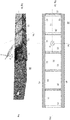
- Fig. 1a shows a schematic top view of an example of a shim tray 10 of the invention.
- the longitudinal rails 41 extend parallel to each other along the longitudinal axis (lng).
- Lateral side walls 21 extend laterally (lat) between the longitudinal rails 41 and form open channels 11 in the transverse direction (tr).
- An individual open channel is bounded by two of the lateral side walls 21 and two opposite parts of the respective longitudinal rails 42.
- the open channels form the so-called shim pockets 11 to hold the shim elements 12.
- the open channels are open in that the shim elements may be inserted along the transverse direction from one or both ends.
- the end shim elements 13 may be inserted laterally to close the shim pocket 11 to hold the shim elements 12 in position.
- Fig. 1b shows a volumetric view of a part of the shim tray of Fig. 1a during mounting of the shim elements in the shim tray, as its shim pockets are being filled with the shim elements.
- Several of the shim pockets are shown, each filled with the shim elements and closed with its end shim element. The most to the right shim pocket is shown empty providing a view along the transverse axis into the open channel.
- One shim element 13 is shown still outside of the open channel as it is being moved along the transverse direction into the channel to be lodged in position in the shim pocket.
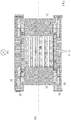
- Fig. 2 shows a schematic side elevation of a part of an example of the shim tray of the invention
- Fig. 2 shows the shim tray of the invention as viewed along the longitudinal direction and the plan of the drawing is in the transverse-lateral plane.
- the example of Fig. 2 shows two end shim elements 13 each at an end of the open channel forming the shim pocket 11.
- Shim elements 12 (by way of example six shim elements are shown) are located in the shim pockets and firmly clamped between the respective end shim elements 13 at either sides of the open channel and hence covering the openings of the channel forming the shim pocket.
- the insertion profiles 22 are shown that are indented longitudinally in lateral side walls and extend laterally.
- the end shim elements can be slid along the lateral directions into the insertion provides where they are held in position in the insertion profiles.
- the shim elements 12 are held firmly in position between the end shim elements 13, which in turn are held in position because their longitudinal extensions fit snugly in the insertion profiles.
- the (end) shim elements 12,13 are firmly fixed and the fixation resists pull of the magnetic field of the main magnet.
- the end shim elements clamp the shim elements between them and the end shim elements are secured by their protrusions in the indent so that the (end) shim elements cannot fall out or be pulled out my the magnetic forces during mounting.
- plastic covers 31 may be provided over the openings of the shim pocket and clamped to the structure of the shim tray 10. These separate covers maybe dispensed with and the end shim elements closing the open channel of the shim pocket.
- the end shim elements' protrusions 23 may make an interference fit with the indents 22 so that the end shim elements are clamped into the indents and remain securely in position.
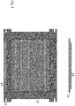
- Fig. 3 shows a schematic side elevation of a part of an example of the shim tray of the invention.
- Fig. 3 shows a further detail on the insertion profiles and further preferred shape of the end shim element 13.
- the example of the shim tray of Fig. 4 has twenty-six shim elements and end shim elements 13 at both ends of the open channel. At both channel ends there is an end shim element with protrusions that fit into lateral indents in the lateral sides walls ate respective channel ends.
- One end shim element at the bottom is shown in position in its indents, another end shim element 13 at the top is shown not yet in position.
- This end shim element at the top is to be slid in position in its space 131 with its protrusions 23 lodged in the indents 22.
- the viewer sees the space for the end shim element bounded at its lateral rear end by the longitudinal wall 12.
- Each end shim element 13 is provided with a protrusion 23 along the lateral direction and extending longitudinally.
- the protrusion's 23 shape corresponds with the shape of the lateral indent 22 and the lateral side wall.
- the lateral side walls strongly support the end shim element in its position so that it can withstand pull by the magnetic field.
- the protrusions fall in the indents and the body of the end shim element rests firmly against the lateral side wall.
Landscapes
- Physics & Mathematics (AREA)
- Condensed Matter Physics & Semiconductors (AREA)
- General Physics & Mathematics (AREA)
- Magnetic Resonance Imaging Apparatus (AREA)
Priority Applications (6)
| Application Number | Priority Date | Filing Date | Title |
|---|---|---|---|
| EP19166707.0A EP3719523A1 (en) | 2019-04-02 | 2019-04-02 | Passive shim tray for magnetic resonance examination system |
| CN202080026641.8A CN113661403B (zh) | 2019-04-02 | 2020-04-01 | 用于磁共振检查系统的被动匀场托盘 |
| EP20714624.2A EP3948325A1 (en) | 2019-04-02 | 2020-04-01 | Passive shim tray for magnetic resonance examination system |
| JP2021557013A JP7460652B2 (ja) | 2019-04-02 | 2020-04-01 | 磁気共鳴検査装置用シムトレイ |
| US17/600,616 US11885859B2 (en) | 2019-04-02 | 2020-04-01 | Passive shim tray for magnetic resonance examination system |
| PCT/EP2020/059301 WO2020201379A1 (en) | 2019-04-02 | 2020-04-01 | Passive shim tray for magnetic resonance examination system |
Applications Claiming Priority (1)
| Application Number | Priority Date | Filing Date | Title |
|---|---|---|---|
| EP19166707.0A EP3719523A1 (en) | 2019-04-02 | 2019-04-02 | Passive shim tray for magnetic resonance examination system |
Publications (1)
| Publication Number | Publication Date |
|---|---|
| EP3719523A1 true EP3719523A1 (en) | 2020-10-07 |
Family
ID=66091893
Family Applications (2)
| Application Number | Title | Priority Date | Filing Date |
|---|---|---|---|
| EP19166707.0A Withdrawn EP3719523A1 (en) | 2019-04-02 | 2019-04-02 | Passive shim tray for magnetic resonance examination system |
| EP20714624.2A Pending EP3948325A1 (en) | 2019-04-02 | 2020-04-01 | Passive shim tray for magnetic resonance examination system |
Family Applications After (1)
| Application Number | Title | Priority Date | Filing Date |
|---|---|---|---|
| EP20714624.2A Pending EP3948325A1 (en) | 2019-04-02 | 2020-04-01 | Passive shim tray for magnetic resonance examination system |
Country Status (5)
| Country | Link |
|---|---|
| US (1) | US11885859B2 (cg-RX-API-DMAC7.html) |
| EP (2) | EP3719523A1 (cg-RX-API-DMAC7.html) |
| JP (1) | JP7460652B2 (cg-RX-API-DMAC7.html) |
| CN (1) | CN113661403B (cg-RX-API-DMAC7.html) |
| WO (1) | WO2020201379A1 (cg-RX-API-DMAC7.html) |
Families Citing this family (1)
| Publication number | Priority date | Publication date | Assignee | Title |
|---|---|---|---|---|
| CN117554873A (zh) * | 2023-11-13 | 2024-02-13 | 中山大学附属第一医院 | 一种磁共振成像设备用的被动匀场填充装置及匀场填充方法 |
Citations (5)
| Publication number | Priority date | Publication date | Assignee | Title |
|---|---|---|---|---|
| US5999076A (en) * | 1998-12-30 | 1999-12-07 | General Electric Company | Magnetic resonance imaging passively shimmed superconducting magnet assembly |
| US20030214300A1 (en) | 2002-03-28 | 2003-11-20 | Franz Bommel | Shim tray, and gradient coils system and magnetic resonance apparatus for the acceptable of the shim tray |
| US20070030004A1 (en) * | 2003-05-30 | 2007-02-08 | Amor William H | Magnetic resonance imaging scanner with molded fixed shims |
| US20130207657A1 (en) * | 2012-02-10 | 2013-08-15 | Nanalysis Corporation | Pole piece |
| CN103576113A (zh) * | 2012-07-26 | 2014-02-12 | 西门子(深圳)磁共振有限公司 | 一种超导磁体及其匀场装置和匀场方法 |
Family Cites Families (18)
| Publication number | Priority date | Publication date | Assignee | Title |
|---|---|---|---|---|
| IL87162A (en) * | 1988-07-20 | 1991-12-15 | Elscint Ltd | System for passively improving magnetic field homogeneity |
| US5389909A (en) * | 1993-11-08 | 1995-02-14 | General Electric Company | Open architecture magnetic resonance imaging passively shimmed superconducting magnet assembly |
| US5635839A (en) * | 1994-11-04 | 1997-06-03 | Picker International, Inc. | High order passive shimming assembly for MRI magnets |
| DE10114319C2 (de) * | 2001-03-23 | 2003-02-13 | Siemens Ag | Shimvorrichtung für ein Magnetresonanzgerät |
| CN201018027Y (zh) * | 2006-10-31 | 2008-02-06 | 达昌电子科技(苏州)有限公司 | 可挠式排线连接器结构 |
| US7589531B2 (en) | 2007-01-17 | 2009-09-15 | Kabushiki Kaisha Toshiba | Gradient magnetic field coil unit, gantry for MRI apparatus, and MRI apparatus |
| JP5203682B2 (ja) * | 2007-02-13 | 2013-06-05 | 株式会社東芝 | Mri装置、nmr分析装置および静磁場発生部 |
| JP4402707B2 (ja) * | 2007-07-06 | 2010-01-20 | 三菱電機株式会社 | 磁場発生装置に対するシムサポートガイド治具 |
| JP5349177B2 (ja) | 2009-07-09 | 2013-11-20 | 株式会社東芝 | 磁気共鳴イメージング装置 |
| GB2483854B (en) | 2010-09-21 | 2014-12-17 | Siemens Plc | Arrangements and method for shimming a magnetic field |
| JP5931666B2 (ja) * | 2012-09-21 | 2016-06-08 | 株式会社日立メディコ | 磁気共鳴撮像装置および磁石装置 |
| JP6245993B2 (ja) * | 2014-01-09 | 2017-12-13 | 東芝メディカルシステムズ株式会社 | 磁気共鳴イメージング装置及びシムトレイ |
| CN203881926U (zh) * | 2014-06-10 | 2014-10-15 | 西门子(深圳)磁共振有限公司 | 一种匀场装置及磁共振设备 |
| GB201416170D0 (en) * | 2014-09-12 | 2014-10-29 | Siemens Plc | Combined shim and bore cooling assembly |
| CN205958735U (zh) * | 2016-05-16 | 2017-02-15 | 上海联影医疗科技有限公司 | 用于磁共振成像的匀场组件及梯度线圈组件 |
| CN206757020U (zh) * | 2016-12-14 | 2017-12-15 | 飞利浦(中国)投资有限公司 | 匀场片组件及核磁共振成像系统 |
| US11156683B2 (en) | 2017-10-26 | 2021-10-26 | Canon Medical Systems Corporation | Static magnetic field adjustment device for magnetic resonance imaging apparatus and superconducting magnet |
| CN107906408B (zh) * | 2017-10-31 | 2025-03-11 | 深圳市豪美照明有限公司 | 一种易安装和拆卸的led面板灯具 |
-
2019
- 2019-04-02 EP EP19166707.0A patent/EP3719523A1/en not_active Withdrawn
-
2020
- 2020-04-01 EP EP20714624.2A patent/EP3948325A1/en active Pending
- 2020-04-01 US US17/600,616 patent/US11885859B2/en active Active
- 2020-04-01 CN CN202080026641.8A patent/CN113661403B/zh active Active
- 2020-04-01 WO PCT/EP2020/059301 patent/WO2020201379A1/en not_active Ceased
- 2020-04-01 JP JP2021557013A patent/JP7460652B2/ja active Active
Patent Citations (5)
| Publication number | Priority date | Publication date | Assignee | Title |
|---|---|---|---|---|
| US5999076A (en) * | 1998-12-30 | 1999-12-07 | General Electric Company | Magnetic resonance imaging passively shimmed superconducting magnet assembly |
| US20030214300A1 (en) | 2002-03-28 | 2003-11-20 | Franz Bommel | Shim tray, and gradient coils system and magnetic resonance apparatus for the acceptable of the shim tray |
| US20070030004A1 (en) * | 2003-05-30 | 2007-02-08 | Amor William H | Magnetic resonance imaging scanner with molded fixed shims |
| US20130207657A1 (en) * | 2012-02-10 | 2013-08-15 | Nanalysis Corporation | Pole piece |
| CN103576113A (zh) * | 2012-07-26 | 2014-02-12 | 西门子(深圳)磁共振有限公司 | 一种超导磁体及其匀场装置和匀场方法 |
Also Published As
| Publication number | Publication date |
|---|---|
| JP2022526916A (ja) | 2022-05-27 |
| WO2020201379A1 (en) | 2020-10-08 |
| US11885859B2 (en) | 2024-01-30 |
| CN113661403A (zh) | 2021-11-16 |
| CN113661403B (zh) | 2024-08-16 |
| US20220171007A1 (en) | 2022-06-02 |
| EP3948325A1 (en) | 2022-02-09 |
| JP7460652B2 (ja) | 2024-04-02 |
Similar Documents
| Publication | Publication Date | Title |
|---|---|---|
| EP0996000B1 (en) | Shim assembly for a pole face of a magnet | |
| US5999076A (en) | Magnetic resonance imaging passively shimmed superconducting magnet assembly | |
| US6700378B2 (en) | Magnetic resonance imaging coil structure having reduced tolerance | |
| US11885859B2 (en) | Passive shim tray for magnetic resonance examination system | |
| EP0999456B1 (en) | Magnet having a shim for a laminated pole piece | |
| EP0714521B1 (en) | Method and apparatus for compensation of field distortion in a magnetic structure using spatial filter | |
| EP2998759A1 (en) | An nmr extractable probe cassette | |
| US5317298A (en) | Apparatus and method for passive shimming of a superconducting magnet which images human limbs | |
| KR102909550B1 (ko) | 자기 조립체가 제공된 자기 공명 이미징 장치 | |
| US20030222650A1 (en) | Shim tray, and gradient coils system and magnetic resonance apparatus for the acceptable of the shim tray | |
| US6798205B2 (en) | Shim tray, and gradient coils system and magnetic resonance apparatus for the acceptable of the shim tray | |
| EP2526436B1 (en) | Magnetic resonance imaging apparatus with means for correcting magnetic field homogeneity | |
| US11156683B2 (en) | Static magnetic field adjustment device for magnetic resonance imaging apparatus and superconducting magnet | |
| US9846209B2 (en) | Homogenization device for homogenization of a magnetic field | |
| GB2337595A (en) | MRI shimset and gradient coil with cutout portions | |
| US20250164591A1 (en) | Shim elements for use with a magnetic resonance apparatus | |
| EP1275973A2 (en) | Open architecture magnetic resonance superconducting magnet with a conical imaging volume | |
| US5900792A (en) | Magnetic field homogeneity correction for superconducting magnet | |
| CN116718968A (zh) | 用于磁共振成像设备的匀场托盘和磁共振成像设备 | |
| GB2438714A (en) | Shim Tray | |
| US7928731B2 (en) | Arrangement to adjust the homogeneity of a basic magnetic field | |
| JP5443276B2 (ja) | 超電導磁石装置 | |
| WO2023049989A1 (en) | Magnet configurations | |
| JPH0438932A (ja) | Mri装置用サーフェスコイル |
Legal Events
| Date | Code | Title | Description |
|---|---|---|---|
| PUAI | Public reference made under article 153(3) epc to a published international application that has entered the european phase |
Free format text: ORIGINAL CODE: 0009012 |
|
| STAA | Information on the status of an ep patent application or granted ep patent |
Free format text: STATUS: THE APPLICATION HAS BEEN PUBLISHED |
|
| AK | Designated contracting states |
Kind code of ref document: A1 Designated state(s): AL AT BE BG CH CY CZ DE DK EE ES FI FR GB GR HR HU IE IS IT LI LT LU LV MC MK MT NL NO PL PT RO RS SE SI SK SM TR |
|
| AX | Request for extension of the european patent |
Extension state: BA ME |
|
| STAA | Information on the status of an ep patent application or granted ep patent |
Free format text: STATUS: THE APPLICATION IS DEEMED TO BE WITHDRAWN |
|
| 18D | Application deemed to be withdrawn |
Effective date: 20210408 |