EP3717318B1 - Adaptives bremshilfesystem für radfahrer auf einem fahrrad mit haptischer rückmeldung - Google Patents
Adaptives bremshilfesystem für radfahrer auf einem fahrrad mit haptischer rückmeldung Download PDFInfo
- Publication number
- EP3717318B1 EP3717318B1 EP18803789.9A EP18803789A EP3717318B1 EP 3717318 B1 EP3717318 B1 EP 3717318B1 EP 18803789 A EP18803789 A EP 18803789A EP 3717318 B1 EP3717318 B1 EP 3717318B1
- Authority
- EP
- European Patent Office
- Prior art keywords
- braking
- module
- bicycle
- cyclist
- wheel
- Prior art date
- Legal status (The legal status is an assumption and is not a legal conclusion. Google has not performed a legal analysis and makes no representation as to the accuracy of the status listed.)
- Active
Links
Images

Classifications
-
- B—PERFORMING OPERATIONS; TRANSPORTING
- B60—VEHICLES IN GENERAL
- B60T—VEHICLE BRAKE CONTROL SYSTEMS OR PARTS THEREOF; BRAKE CONTROL SYSTEMS OR PARTS THEREOF, IN GENERAL; ARRANGEMENT OF BRAKING ELEMENTS ON VEHICLES IN GENERAL; PORTABLE DEVICES FOR PREVENTING UNWANTED MOVEMENT OF VEHICLES; VEHICLE MODIFICATIONS TO FACILITATE COOLING OF BRAKES
- B60T8/00—Arrangements for adjusting wheel-braking force to meet varying vehicular or ground-surface conditions, e.g. limiting or varying distribution of braking force
- B60T8/17—Using electrical or electronic regulation means to control braking
- B60T8/1701—Braking or traction control means specially adapted for particular types of vehicles
- B60T8/1706—Braking or traction control means specially adapted for particular types of vehicles for single-track vehicles, e.g. motorcycles
-
- B—PERFORMING OPERATIONS; TRANSPORTING
- B60—VEHICLES IN GENERAL
- B60T—VEHICLE BRAKE CONTROL SYSTEMS OR PARTS THEREOF; BRAKE CONTROL SYSTEMS OR PARTS THEREOF, IN GENERAL; ARRANGEMENT OF BRAKING ELEMENTS ON VEHICLES IN GENERAL; PORTABLE DEVICES FOR PREVENTING UNWANTED MOVEMENT OF VEHICLES; VEHICLE MODIFICATIONS TO FACILITATE COOLING OF BRAKES
- B60T8/00—Arrangements for adjusting wheel-braking force to meet varying vehicular or ground-surface conditions, e.g. limiting or varying distribution of braking force
- B60T8/17—Using electrical or electronic regulation means to control braking
- B60T8/1755—Brake regulation specially adapted to control the stability of the vehicle, e.g. taking into account yaw rate or transverse acceleration in a curve
- B60T8/17551—Brake regulation specially adapted to control the stability of the vehicle, e.g. taking into account yaw rate or transverse acceleration in a curve determining control parameters related to vehicle stability used in the regulation, e.g. by calculations involving measured or detected parameters
-
- B—PERFORMING OPERATIONS; TRANSPORTING
- B60—VEHICLES IN GENERAL
- B60T—VEHICLE BRAKE CONTROL SYSTEMS OR PARTS THEREOF; BRAKE CONTROL SYSTEMS OR PARTS THEREOF, IN GENERAL; ARRANGEMENT OF BRAKING ELEMENTS ON VEHICLES IN GENERAL; PORTABLE DEVICES FOR PREVENTING UNWANTED MOVEMENT OF VEHICLES; VEHICLE MODIFICATIONS TO FACILITATE COOLING OF BRAKES
- B60T8/00—Arrangements for adjusting wheel-braking force to meet varying vehicular or ground-surface conditions, e.g. limiting or varying distribution of braking force
- B60T8/24—Arrangements for adjusting wheel-braking force to meet varying vehicular or ground-surface conditions, e.g. limiting or varying distribution of braking force responsive to vehicle inclination or change of direction, e.g. negotiating bends
- B60T8/241—Lateral vehicle inclination
-
- B—PERFORMING OPERATIONS; TRANSPORTING
- B60—VEHICLES IN GENERAL
- B60T—VEHICLE BRAKE CONTROL SYSTEMS OR PARTS THEREOF; BRAKE CONTROL SYSTEMS OR PARTS THEREOF, IN GENERAL; ARRANGEMENT OF BRAKING ELEMENTS ON VEHICLES IN GENERAL; PORTABLE DEVICES FOR PREVENTING UNWANTED MOVEMENT OF VEHICLES; VEHICLE MODIFICATIONS TO FACILITATE COOLING OF BRAKES
- B60T8/00—Arrangements for adjusting wheel-braking force to meet varying vehicular or ground-surface conditions, e.g. limiting or varying distribution of braking force
- B60T8/32—Arrangements for adjusting wheel-braking force to meet varying vehicular or ground-surface conditions, e.g. limiting or varying distribution of braking force responsive to a speed condition, e.g. acceleration or deceleration
- B60T8/321—Arrangements for adjusting wheel-braking force to meet varying vehicular or ground-surface conditions, e.g. limiting or varying distribution of braking force responsive to a speed condition, e.g. acceleration or deceleration deceleration
- B60T8/3225—Systems specially adapted for single-track vehicles, e.g. motorcycles
-
- B—PERFORMING OPERATIONS; TRANSPORTING
- B62—LAND VEHICLES FOR TRAVELLING OTHERWISE THAN ON RAILS
- B62K—CYCLES; CYCLE FRAMES; CYCLE STEERING DEVICES; RIDER-OPERATED TERMINAL CONTROLS SPECIALLY ADAPTED FOR CYCLES; CYCLE AXLE SUSPENSIONS; CYCLE SIDECARS, FORECARS, OR THE LIKE
- B62K23/00—Rider-operated controls specially adapted for cycles, i.e. means for initiating control operations, e.g. levers, grips
- B62K23/02—Rider-operated controls specially adapted for cycles, i.e. means for initiating control operations, e.g. levers, grips hand actuated
-
- B—PERFORMING OPERATIONS; TRANSPORTING
- B62—LAND VEHICLES FOR TRAVELLING OTHERWISE THAN ON RAILS
- B62L—BRAKES SPECIALLY ADAPTED FOR CYCLES
- B62L3/00—Brake-actuating mechanisms; Arrangements thereof
- B62L3/02—Brake-actuating mechanisms; Arrangements thereof for control by a hand lever
-
- B—PERFORMING OPERATIONS; TRANSPORTING
- B60—VEHICLES IN GENERAL
- B60T—VEHICLE BRAKE CONTROL SYSTEMS OR PARTS THEREOF; BRAKE CONTROL SYSTEMS OR PARTS THEREOF, IN GENERAL; ARRANGEMENT OF BRAKING ELEMENTS ON VEHICLES IN GENERAL; PORTABLE DEVICES FOR PREVENTING UNWANTED MOVEMENT OF VEHICLES; VEHICLE MODIFICATIONS TO FACILITATE COOLING OF BRAKES
- B60T2201/00—Particular use of vehicle brake systems; Special systems using also the brakes; Special software modules within the brake system controller
- B60T2201/03—Brake assistants
-
- B—PERFORMING OPERATIONS; TRANSPORTING
- B60—VEHICLES IN GENERAL
- B60T—VEHICLE BRAKE CONTROL SYSTEMS OR PARTS THEREOF; BRAKE CONTROL SYSTEMS OR PARTS THEREOF, IN GENERAL; ARRANGEMENT OF BRAKING ELEMENTS ON VEHICLES IN GENERAL; PORTABLE DEVICES FOR PREVENTING UNWANTED MOVEMENT OF VEHICLES; VEHICLE MODIFICATIONS TO FACILITATE COOLING OF BRAKES
- B60T2201/00—Particular use of vehicle brake systems; Special systems using also the brakes; Special software modules within the brake system controller
- B60T2201/04—Hill descent control
Definitions
- the present invention refers to a brake assist system for a cyclist on a bicycle by an haptic feedback, particularly a system adapted to aid the cyclist to prevent a braking wheel from excessively slipping (consequently from loosing the lateral stability), or from possibly flipping over the bicycle, due to too high decelerations.
- the system according to the invention is configured to adapt to the ability of a cyclist.
- Braking a bicycle, especially the front wheel thereof, is an action requiring a cyclist to have a determined sensibility and if he/she does not correctly brake, risks and problems can rise.
- an improperly modulated braking particularly a too intense braking, can cause dangerous slippages which can cause falls.
- bicycles provided with large wheels and tires, such as mountain bikes slipping is less risky, however on the other side the same large tire, in case of a too intense braking of the front wheel, can cause the bicycle itself to flip over around this wheel.
- an object of the present invention is that of providing a brake assist system for a cyclist on a bicycle by an haptic feedback capable of adapting to the driving skillfulness of each specific cyclist.
- an adaptive brake assist system for a cyclist on a bicycle by an haptic feedback according to claim 1.
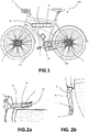
- reference 100 generally indicates a bicycle.
- the bicycle 100 comprises a first 101 and second wheels 102, for example corresponding to the front wheel and rear wheel.
- a brake is associated to at least the first wheel 101, the brake being actuatable by a knob located on the handlebar, for example.
- the braking system can be of any known type, for example a pad or disk brake, commanded by a mechanical system, for example a cable or hydraulic system.
- the bicycle 100 comprises a brake assist system 1 for a cyclist of the bicycle itself.
- the system 1 does not actively control the braking, on the contrary it communicates, by a vibrating haptic feedback, to the cyclist the emergence of possibly dangerous events, particularly the slippage or a possible slippage of the first wheel 101, or the initial flipping-over of the bicycle around the same due to a braking.
- the slippage events are typical of bicycles having narrow wheels and tires, for example racing bicycles, while the flipping-over is typical of bicycles having large wheels and tires, for example mountain bikes.
- the basic principle of the system is the same and consists of correcting the slippage for preventing the flipping-over, according to the type of a considered bicycle, in other words to provide a vibrating haptic feedback advising the cyclist about a dangerous condition.
- the system 1 comprises an actuator 4 adapted to generate vibrations.
- the actuator 4 can comprise an eccentric mass such to generate vibrations when is rotated.
- the actuator 4 can be mounted to a portion of the bicycle so that, when the actuator vibrates, the vibrations can be perceived by the cyclist.
- the actuator 4 is mounted to the brake lever of the first wheel 101, which is the wheel subjected to a slippage or around which a flipping-over caused by an excessively intense brake can occur. Therefore, the vibrating feedback is transferred to the lever on which the cyclist must act for modulating the braking.
- the actuator 4 can for example be received inside a groove 32 typically present in the rear portion of the brake lever 33.
- the actuator 4 can be placed in the groove 32 for example by a housing, not shown in the figures, configured to close the groove 32 for protecting the actuator 4 from the weather, besides preventing the cyclist hand from contacting the actuator 4 itself.
- the actuator 4 is made integral to the brake lever 33 by the housing.
- the actuator is supplied and controlled by electric wires 37.
- the actuator 4 is of a DC brushed type and can be voltage- or current-controlled.
- a battery 23 is preferably associated to the actuator 4 for supplying and moving the latter.
- the system 1 comprises a first sensor 2 for measuring the angular speed ⁇ 1 of the first wheel 101, particularly of the front wheel.
- the first sensor 2 is adapted to generate a signal representative of such angular speed of the first wheel.
- Such first sensor 2 can transmit the signal representative of the angular speed ⁇ 1 of the first wheel 101 either wirelessly or by wire.
- the system 1 can further comprise a second sensor 3 for measuring the angular speed ⁇ 2 of the second wheel 102, particularly of the rear wheel.
- the bicycle speed v can be used by the system 1, according to the invention, as it will be explained in the following.
- the bicycle speed if is necessary, can be alternatively derived from other sensors, for example inertial sensors, so that the second sensor 3 for measuring the angular speed ⁇ 2 of the second wheel 102 can be omitted.
- the system further comprises a module for determining the slope angle ⁇ of the bicycle, in other words the road slope, and adapted to supply a signal representing the same. This can be calculated in different ways.
- the module for determining the slope ⁇ comprises a dedicated slope sensor adapted to supply a signal representing the same.
- the slope ⁇ can be obtained from signals representing inertial magnitudes of the bicycle, for example according to what is described in: M. Corno, P. Spagnol, S. M. Savaresi S "Road Slope Estimation in Bicycles without Torque Measurements".
- the system 1 can comprise an inertial measuring unit 18 adapted to measure one or more among the longitudinal a x , lateral a y and vertical accelerations a z , and/or one or more among the roll ⁇ x , yaw ⁇ y , and pitch angular speeds ⁇ z of the bicycle, and adapted to generate signals representing the same.
- the inertial measuring unit 18 can be advantageously further used for further operations of the system 1 according to the invention.
- the speed v of the bicycle can be calculated by integrating over time limited intervals the longitudinal acceleration a x supplied by the inertial measuring unit 18.
- the system 1 comprises a sensor for detecting the braking action of a user, adapted to supply a signal representing the same.
- a sensor for detecting the braking action of a user, adapted to supply a signal representing the same.
- such sensor can comprise a switch (not shown in the figures) coupled with the brake lever 33, capable of detecting when this is actuated by the cyclist.
- the braking can be detected also without such sensor, particularly by the signal from the speed sensor 2 of the first wheel 101.
- the system 1 comprises a module for detecting a pedal-thrust input of the cyclist (not shown in the figures).
- a pedal-thrust input of the cyclist can comprise a pedal-thrust torque sensor mounted to the bicycle pedals, or a pedal-thrust speed sensor, mounted to the pedals or a free-wheel mechanism preferably placed at the rear wheel, wherein the chain unloads the driving torque applied by the cyclist to the wheel.
- the pedal-thrust input can be obtained from signals supplied by the angular speed sensor 2 of the first wheel 101 and/or by the inertial measuring unit 18 according to known estimate algorithms.
- the pedal-thrust rate is possibly obtained from what is disclosed in the patent application WO 2017/089904 filed by the Applicant, the contents thereof being herein incorporated by reference.
- the system 1 comprises a control module 5 adapted to generate a command signal to the actuator 4 so that this latter vibrates at a determined vibration frequency f.
- the command signal to the actuator can be determined based on signals from one or more of the system 1 sensors and based on one or more reference magnitudes.
- the system further comprises a learning module 50 configured to determine and supply to the control module 5 said one or more reference magnitudes.
- the one or more reference magnitudes, as determined by the learning module 50 represent the skillfulness of a cyclist, and are determined based on signals from one or more of the system 1 sensors, according to what will be described in the following.
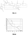
- Figure 3 shows the block 6 representing the cyclist, which acts with a determined force F c on the brake lever for actuating the first wheel brake. Consequently, the bicycle braking system, represented by block 7, transforms such force F c into a braking torque T on the first wheel.
- the block 8 represents the bicycle and takes into consideration the dynamics established by the tire and road, which can determine a slippage of the first wheel with respect to the road. This is due to several factors, among them the road conditions, tire conditions, road slope, bicycle roll angle.
- the control module 5 comprises a module 24 for estimating the (linear) deceleration ⁇ of the first wheel.
- the control module 5 determines the vibration frequency f that the actuator 4 must have, based on a static map stored in a memory module 25 of the control module itself.
- Figure 4 shows two possible curves establishing a relationship between the vibration frequency and the deceleration error e ⁇ .
- a discontinuity is provided when the deceleration error e ⁇ is zero.
- the derivative is equal to zero. Consequently, the frequency f stays about constant and is subjected to minimal variations about such condition.
- the vibration frequency f of the actuator is also affected by the effective speed v of the bicycle.
- the frequency determined based on the static map of the memory module 25 is amplified by a factor kv, wherein k is a constant and v is the bicycle speed.
- k is a constant
- v is the bicycle speed.
- This latter can be determined from the signal representing the longitudinal acceleration a x , supplied by the inertial measuring unit 18, or from the signal representing the angular speed ⁇ 2 of the second wheel, if present. Therefore, the frequency f depends on the bicycle speed v, particularly is amplified as the bicycle speed v increases.
- the learning module 50 can be configured to supply to the control module the reference deceleration ⁇ ref .
- the learning module 50 determines and updates a cyclist profile as he/she uses the bicycle, and determines the reference deceleration ⁇ ref , by also progressively updating it.
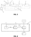
- Figure 6 shows a schematic representation of the learning module 50 according to a possible embodiment of the invention.
- the learning module 50 comprises a braking detecting module 51 configured to detect when a cyclist is braking.
- the module 51 can determine the occurrence of a braking if it receives, at the input, the signal from the previously cited braking sensor, if is present.
- the braking sensor If the braking sensor is omitted, it is possible to determine the occurrence of a braking, by the signal representing the angular speed ⁇ 1 of the first wheel.
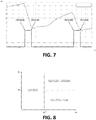
- Figure 7 shows a possible trend during time t of such speed, wherein two abrupt reductions of the same are shown, having a start ("start braking") and a stop (“stop braking”) corresponding to the breakings.
- the module 51 finds the brakings because it performs an analysis of the angular speed ⁇ 1 of the first wheel during time t.
- the brakings are analytically detectable for example by analyzing the angular acceleration (obtainable by time deriving the angular speed ⁇ 1 of the first wheel) and the jerk (obtainable by time deriving the angular acceleration of the first wheel) of the first wheel.
- the angular acceleration of the first wheel will jump, while the angular jerk of the first wheel will show a peak during braking.
- the module 51 generates a signal indicative of the presence of a braking ("brake").
- the learning module 50 comprises a braking classifying module 52 configured to classify each braking event based on at least the signal representing the first wheel speed ⁇ 1 , preferably further based on the signal representing the slope ⁇ and to output, at each braking event detected by the braking detection module 51, one or more parameters representing such classification.
- a braking classifying module 52 configured to classify each braking event based on at least the signal representing the first wheel speed ⁇ 1 , preferably further based on the signal representing the slope ⁇ and to output, at each braking event detected by the braking detection module 51, one or more parameters representing such classification.
- FIG 8 it shows a diagram of a possible braking classification.
- the abscissa represents the speed ⁇ 1 of the first wheel, and the ordinate the slope ⁇ .
- the diagram shows three quadrants:
- a threshold speed ⁇ 1 * separating the low speed from the high speed.
- the braking is determined as a downhill or plain braking based on a threshold slope, preferably equal to 0° (eventually ⁇ a constant).
- a threshold slope preferably equal to 0° (eventually ⁇ a constant).
- the parameters representing the braking can include, for example, a more or less high score, based on the tendency of the cyclist to brake at high or low speeds, along downhill or on plain.
- the classification can be only performed based on the angular speed of the first wheel.
- the braking classifying module 52 is configured to further classify the braking based on the roll angle of the bicycle and/or based on the pedal-thrust input detected before braking.
- the bicycle roll angle can be obtained from the signal representing the roll angular speed ⁇ x supplied by the inertial measuring unit 18, while the pedal-thrust input can be detected by the beforehand cited module for detecting the pedal-thrust input (the torque or speed/pedal-thrust rate).
- the learning module 50 further comprises a module for optimizing the reference magnitudes 53, configured to receive at the input the parameters representing the braking classification, supplied by the module 52, and to generate a cyclist profile by a progressive update. Moreover, the module for optimizing the reference magnitudes 53, based on the progressively updated profile, determines the reference magnitudes supplied to the control module 5. With reference to the embodiments shown in Figures 3 and 5 , the module for optimizing the reference magnitudes 53 can for example determine and update, during the cyclist run, the reference deceleration ⁇ ref . Therefore, if the cyclist is classified as prudent, the reference deceleration ⁇ ref could assume a low value (in absolute value) while, if the cyclist is more aggressive, the reference deceleration could assume a higher value (in absolute value).
- the module for optimizing the reference magnitudes 53 can further receive, at the input, in order to determine the reference magnitudes, one or more of the following information:
- the system 1 can for example comprise a GPS module for geopositioning the bicycle during the motion thereof.
- said information can be locally saved in a memory module of the system 1.
- the information can be stored in a remote system 54, for example in a cloud system.
- the system 1 can comprise a transmission module for supplying and receiving data to/from the remote system.
- the system 1 can be connected to a mobile device of the cyclist, for example a smartphone, storing a dedicated application.
- a hybrid system can be further provided in which some information are locally saved, and other information are remotely saved.
- control module 5 can be configured according to each of the embodiment variants described in the international patent application WO 2016/203331 , the content thereof being integrally incorporated by reference.
- the reference magnitudes which can be updated by the learning module 50 can include:
- the actuator 4 can be voltage- or current-controlled.
- the system 1 comprises a voltage-control module of the actuator (not shown in the figures) receiving, at the input, the command signal, and consequently supplying the actuator 4 with a voltage adapted to vibrate the actuator at the determined vibration frequency.
- the system 1 comprises a current-control module 34 of the actuator, schematically illustrated in Figure 9 .
- the module 34 receives, at the input, the desired vibration frequency determined by the previously described modes, indicated in this case as a reference frequency f ref .
- the module 34 comprises a memory module 35 storing a static map relating the reference vibration frequency f ref to a reference current l ref .
- An example of such map is shown in Figure 10 . Therefore, a reference current l ref corresponding to the reference vibration frequency f ref is obtained at the output of the memory module 35.
- the module 34 performs a closed-loop control of the actuator current 4.
- the module 34 comprises a current sensor measuring the motor effective current l, from which a current error ei between the reference current l ref and effective current l is determined.
- the module 34 comprises a voltage command module 36 determining the DC (duty cycle) voltage to be applied across the actuator 4 so that the current error ei is minimized, in other words so that the effective current l substantially follows the trend of the reference current l ref . Due to the current l set in this way, the actuator 4 will vibrate at an effective frequency f which follows the trend of the reference frequency f ref .
- Such current-control method enables to have faster response times than the ones of the voltage-control, and further enables to prevent too high currents from flowing in the actuator 4.
- system 1 and also the elements indicated by the term “module”, can be implemented by hardware devices (control units, for example), by software or by a hardware and software combination.
Landscapes
- Engineering & Computer Science (AREA)
- Mechanical Engineering (AREA)
- Transportation (AREA)
- Regulating Braking Force (AREA)
- Motorcycle And Bicycle Frame (AREA)
Claims (14)
- Adaptives Bremshilfesystem (1) für einen Radfahrer auf einem Fahrrad (100) durch eine haptische Rückmeldung, das Folgendes umfasst:- einen ersten Sensor (2) zum Messen der Winkelgeschwindigkeit (ω1) eines ersten Rads (101) des Fahrrads, der angepasst ist, um ein Signal zu erzeugen, das die Winkelgeschwindigkeit des ersten Rads (101) repräsentiert;- einen Aktuator (4), der an einem Abschnitt des Fahrrads montierbar ist, der angepasst ist, um Vibrationen zu erzeugen;- ein Steuermodul (5), das zum Erzeugen eines Befehlssignals des Aktuators (4), so dass der Aktuator mit einer Vibrationsfrequenz (f) vibriert, basierend auf wenigstens dem Signal, das die Winkelgeschwindigkeit des ersten Rads (ω1) repräsentiert, und basierend auf einer oder mehreren Referenzgrößen (ηref) konfiguriert ist;dadurch gekennzeichnet, dass es ferner Folgendes umfasst:- ein Lernmodul (50), zum Bestimmen, Aktualisieren und Liefern, an das Steuermodul (5), der einen oder mehreren Referenzgrößen (ηref) basierend auf wenigstens dem Signal, das die Winkelgeschwindigkeit (ω1) des ersten Rads (101) repräsentiert, konfiguriert ist,
wobei das Lernmodul (50) Folgendes umfasst:ein Modul zum Erfassen des Bremsens (51), das zum Erfassen, wenn der Radfahrer bremst, und zum Ausgeben eines Signals, das das Bremsvorhandensein repräsentiert, konfiguriert ist, undein Bremsklassifizierungsmodul (52), das zum Klassifizieren jedes Bremsereignisses, wie es durch das Bremserfassungsmodul (51) erfasst wird, basierend auf wenigstens dem Signal, das die Winkelgeschwindigkeit des ersten Rads (ω1) repräsentiert, und zum Liefern eines oder mehrerer Parameter, die eine derartige Klassifizierung des Bremsens repräsentieren, konfiguriert ist. - System (1) nach Anspruch 1, das ferner ein Modul zum Bestimmen des Neigungswinkels (θ) des Fahrrads konfiguriert ist, das angepasst ist, um ein Signal zu liefern, das das gleiche repräsentiert, wobei das Lernmodul (50) zum Bestimmen, Aktualisieren und Liefern, an das Steuermodul (5), der einen oder der mehreren Referenzgrößen (ηref) ferner basierend auf der Neigung (θ) des Fahrrads konfiguriert ist.
- System (1) nach Anspruch 1 oder 2, das eine inertiale Messeinheit (18) umfasst, die angepasst ist, um die longitudinale (ax) und/oder die laterale (ay) und/oder die vertikale Beschleunigung (az) und/oder die Roll- (ωx) und/oder die Nick- (ωy) und/oder die Gier(ωz)-Winkelgeschwindigkeit des Fahrrads zu messen und um Signale zu erzeugen, die das gleiche repräsentieren.
- System (1) nach Anspruch 2 oder 3, wobei das Modul zum Bestimmen der Neigung (θ) einen Neigungssensor umfasst, der angepasst ist, um ein Signal zu liefern, das das gleiche repräsentiert.
- System (1) nach den Ansprüchen 2 und 3, wobei das Modul zum Bestimmen der Neigung (θ) zum Bestimmen des Signals, das die Neigung (θ) repräsentiert, aus den Signalen der inertialen Messeinheit (18) konfiguriert ist.
- System (1) nach einem der Ansprüche von 1 bis 5, wobei das Bremserfassungsmodul (51) einen Sensor zum Erfassen der Bremswirkung durch einen Benutzer umfasst, das angepasst ist, um ein Signal zu liefern, das das gleiche repräsentiert.
- System (1) nach einem der Ansprüche von 1 bis 5, wobei das Bremserfassungsmodul (51) zum Erfassen, wenn der Radfahrer bremst, basierend auf dem Signal, das die Winkelgeschwindigkeit des ersten Rads (ω1) repräsentiert, konfiguriert ist.
- System (1) nach Anspruch 2 oder nach einem der vorhergehenden Ansprüche, wenn abhängig von Anspruch 2, wobei das Bremsklassifizierungsmodul (52) zum Klassifizieren jedes Bremsereignisses, wie es durch das Bremserfassungsmodul (51) erfasst wird, und zum Liefern des einen oder der mehreren Parameter, die die derartige Klassifizierung des Bremsens repräsentieren, ferner basierend auf dem Signal, das die Steigung (θ) repräsentiert, konfiguriert ist.
- System (1) nach Anspruch 3 oder nach einem der vorhergehenden Ansprüche, wenn abhängig von Anspruch 3, wobei das Bremsklassifizierungsmodul (52) zum Klassifizieren jedes Bremsereignisses, wie es durch das Bremserfassungsmodul (51) erfasst wird, und zum Liefern des einen oder der mehreren Parameter, die die derartige Klassifizierung des Bremsens repräsentieren, ferner basierend auf dem Rollwinkel des Fahrrads, wie aus dem Signal bestimmt, das die Rollwinkelgeschwindigkeit (ωx) repräsentiert, die vor dem Bremsen erfasst wird, konfiguriert ist.
- System (1) nach einem der vorhergehenden Ansprüche, das ein Modul zum Erkennen einer Pedalschubeingabe von einem Radfahrer umfasst, das angepasst ist, um ein Signal zu liefern, das das gleiche repräsentiert, wobei das Bremsklassifizierungsmodul (52) zum Klassifizieren jedes Bremsereignisses, wie es durch das Bremserfassungsmodul (51) erfasst wird, und zum Liefern des einen oder der mehreren Parameter, die die derartige Klassifizierung des Bremsens repräsentieren, ferner basierend auf dem Signal, das die Pedalschubeingabe von dem Radfahrer repräsentiert, die vor dem Bremsen erfasst wird, konfiguriert ist.
- System (1) nach einem der vorhergehenden Ansprüche, wobei das Lernmodul (50) ferner ein Modul zum Optimieren der Referenzgrößen (53) umfasst, das für Folgendes konfiguriert ist:- Erzeugen eines Radfahrerprofils durch fortschreitendes Aktualisieren desselben, basierend auf einem oder mehreren Parametern, die die Klassifizierung des Bremsens repräsentieren;- Bestimmen der einen oder der mehreren Referenzgrößen (ηref) basierend auf dem Radfahrerprofil.
- System (1) nach Anspruch 11, wobei das Referenzgrößenoptimierungsmodul (53) zum Erzeugen des Radfahrerprofils ferner basierend auf dem Geschlecht des Radfahrers und/oder dem Alter des Radfahrers und/oder der Art des Fahrrads und/oder der Art der Bremsen und/oder basierend auf dem Standort konfiguriert ist.
- System (1) nach einem der vorhergehenden Ansprüche, wobei das erste Rad (101) ein Vorderrad des Fahrrads (100) ist.
- Fahrrad (100), das ein erstes (101) und ein zweites Rad (102), einen Bremshebel (33) zum Bremsen des ersten (101) oder des zweiten Rads (102) und ein adaptives Bremshilfesystem nach einem der vorhergehenden Ansprüche umfasst.
Applications Claiming Priority (2)
| Application Number | Priority Date | Filing Date | Title |
|---|---|---|---|
| IT201700135958 | 2017-11-27 | ||
| PCT/IB2018/058767 WO2019102290A1 (en) | 2017-11-27 | 2018-11-08 | Adaptive brake assist system for a cyclist on a bicycle by an aptic feedback |
Publications (2)
| Publication Number | Publication Date |
|---|---|
| EP3717318A1 EP3717318A1 (de) | 2020-10-07 |
| EP3717318B1 true EP3717318B1 (de) | 2021-12-22 |
Family
ID=61581519
Family Applications (1)
| Application Number | Title | Priority Date | Filing Date |
|---|---|---|---|
| EP18803789.9A Active EP3717318B1 (de) | 2017-11-27 | 2018-11-08 | Adaptives bremshilfesystem für radfahrer auf einem fahrrad mit haptischer rückmeldung |
Country Status (5)
| Country | Link |
|---|---|
| US (1) | US11260836B2 (de) |
| EP (1) | EP3717318B1 (de) |
| JP (1) | JP7219277B2 (de) |
| CN (1) | CN111741878B (de) |
| WO (1) | WO2019102290A1 (de) |
Families Citing this family (8)
| Publication number | Priority date | Publication date | Assignee | Title |
|---|---|---|---|---|
| JP7156908B2 (ja) * | 2018-10-31 | 2022-10-19 | 株式会社シマノ | 制御装置および検出装置 |
| IT201900004069A1 (it) * | 2019-03-20 | 2020-09-20 | Blubrake S R L | Sistema per il miglioramento delle prestazioni di un ciclista su una bicicletta |
| CN111307172B (zh) * | 2020-03-03 | 2022-11-08 | 北京骑胜科技有限公司 | 一种自行车以及确定自行车骑行信息的方法 |
| US12151770B2 (en) | 2021-12-22 | 2024-11-26 | Zero Motorcycles, Inc. | Switchgear for vehicle and vehicle including switchgear |
| CN114872725B (zh) * | 2022-05-30 | 2023-04-14 | 大拓无限(重庆)智能科技有限公司 | 电动两轮车智能控制系统 |
| EP4357152B1 (de) * | 2022-10-19 | 2025-08-20 | Hochschule Für Angewandte Wissenschaften München | Antiblockier-bremssystem |
| DE102023202197A1 (de) | 2023-03-10 | 2024-09-12 | Robert Bosch Gesellschaft mit beschränkter Haftung | Verfahren zur Ausgabe einer Information zu einem Verzögerungsvorgang |
| CN119718087B (zh) * | 2025-02-25 | 2025-06-20 | 厦门理工学院 | 一种用于骑行者的可穿戴式多模态触觉反馈系统的交互方法 |
Family Cites Families (10)
| Publication number | Priority date | Publication date | Assignee | Title |
|---|---|---|---|---|
| JP2006193069A (ja) * | 2005-01-14 | 2006-07-27 | Toyota Motor Corp | 車両用警報装置 |
| US7944343B2 (en) * | 2007-10-07 | 2011-05-17 | Audi Ag | System and method for providing information in a vehicle |
| FR2923596B1 (fr) * | 2007-11-09 | 2010-01-15 | Michelin Soc Tech | Systeme de controle du comportement au sol d'un vehicule comportant une determination de la pente du sol de roulement 1 |
| JP2010061608A (ja) * | 2008-09-08 | 2010-03-18 | Denso Corp | 物体検出装置 |
| DE102013205245A1 (de) * | 2013-03-25 | 2014-09-25 | Continental Teves Ag & Co. Ohg | Fahrzeugreferenzgeschwindigkeitsbestimmungsverfahren und Fahrzeugsteuergerät mit einem solchen Verfahren |
| GB201311001D0 (en) * | 2013-06-20 | 2013-08-07 | Lucabella Holdings Llc | Lucabella |
| EP3936363B1 (de) * | 2015-01-12 | 2025-04-30 | Harman International Industries, Incorporated | Kognitive-last-fahrassistent |
| JP6764476B2 (ja) * | 2015-06-19 | 2020-09-30 | ブルブレーク エス.アール.エル.Blubrake S.R.L. | 触覚フィードバックによる自転車運転者のためのブレーキアシストシステム |
| CN105711701A (zh) * | 2015-12-31 | 2016-06-29 | 天津百世达科技有限公司 | 一种智能自行车 |
| ITUB20160057A1 (it) * | 2016-02-04 | 2017-08-04 | E Novia S P A | Sistema di assistenza alla guida di una bicicletta mediante invio di un feedback aptico al ciclista |
-
2018
- 2018-11-08 WO PCT/IB2018/058767 patent/WO2019102290A1/en not_active Ceased
- 2018-11-08 JP JP2020528954A patent/JP7219277B2/ja active Active
- 2018-11-08 CN CN201880082191.7A patent/CN111741878B/zh not_active Expired - Fee Related
- 2018-11-08 US US16/766,785 patent/US11260836B2/en active Active
- 2018-11-08 EP EP18803789.9A patent/EP3717318B1/de active Active
Also Published As
| Publication number | Publication date |
|---|---|
| WO2019102290A1 (en) | 2019-05-31 |
| CN111741878A (zh) | 2020-10-02 |
| US11260836B2 (en) | 2022-03-01 |
| CN111741878B (zh) | 2022-06-14 |
| US20200298809A1 (en) | 2020-09-24 |
| JP7219277B2 (ja) | 2023-02-07 |
| JP2021504219A (ja) | 2021-02-15 |
| EP3717318A1 (de) | 2020-10-07 |
Similar Documents
| Publication | Publication Date | Title |
|---|---|---|
| EP3717318B1 (de) | Adaptives bremshilfesystem für radfahrer auf einem fahrrad mit haptischer rückmeldung | |
| JP6764476B2 (ja) | 触覚フィードバックによる自転車運転者のためのブレーキアシストシステム | |
| EP3411285B1 (de) | System zur unterstützung des antriebs eines fahrrads durch senden eines haptischen feedbacks an einen radfahrer | |
| CN103448552A (zh) | 车辆用显示装置 | |
| EP2974900A1 (de) | Grätschsitzfahrzeug | |
| US10040509B1 (en) | Control system for electric bicycles | |
| JP6067939B2 (ja) | ピッチ角制御システム、ピッチ角制御方法および車両 | |
| KR101243075B1 (ko) | 차량의 적응형 순항제어시스템의 제어방법 및 제어장치 | |
| CN110225850B (zh) | 用于自行车上的骑车人的制动辅助系统 | |
| JP2008522886A (ja) | 車両の重心の高さを決定する装置及び方法 | |
| WO2016124629A1 (en) | Control system | |
| KR101308355B1 (ko) | 차량 안정성 제어 시스템 | |
| JP2006117102A (ja) | 車両用走行制御装置 | |
| JP6248508B2 (ja) | 車両の運転支援装置 | |
| KR20140133276A (ko) | 차량의 사륜 구동 제어 방법 | |
| JP2006056383A (ja) | 車体スリップ角推定方法 | |
| CN107635839A (zh) | 用于探测车辆的已激活的制动器的方法和设备 | |
| KR20170064269A (ko) | 차량의 전자식 자세 제어 방법 및 시스템 | |
| KR20160147306A (ko) | 차량 구동력 제어 장치 및 방법 |
Legal Events
| Date | Code | Title | Description |
|---|---|---|---|
| STAA | Information on the status of an ep patent application or granted ep patent |
Free format text: STATUS: UNKNOWN |
|
| STAA | Information on the status of an ep patent application or granted ep patent |
Free format text: STATUS: THE INTERNATIONAL PUBLICATION HAS BEEN MADE |
|
| PUAI | Public reference made under article 153(3) epc to a published international application that has entered the european phase |
Free format text: ORIGINAL CODE: 0009012 |
|
| STAA | Information on the status of an ep patent application or granted ep patent |
Free format text: STATUS: REQUEST FOR EXAMINATION WAS MADE |
|
| 17P | Request for examination filed |
Effective date: 20200527 |
|
| AK | Designated contracting states |
Kind code of ref document: A1 Designated state(s): AL AT BE BG CH CY CZ DE DK EE ES FI FR GB GR HR HU IE IS IT LI LT LU LV MC MK MT NL NO PL PT RO RS SE SI SK SM TR |
|
| AX | Request for extension of the european patent |
Extension state: BA ME |
|
| DAV | Request for validation of the european patent (deleted) | ||
| DAX | Request for extension of the european patent (deleted) | ||
| GRAP | Despatch of communication of intention to grant a patent |
Free format text: ORIGINAL CODE: EPIDOSNIGR1 |
|
| STAA | Information on the status of an ep patent application or granted ep patent |
Free format text: STATUS: GRANT OF PATENT IS INTENDED |
|
| INTG | Intention to grant announced |
Effective date: 20210716 |
|
| GRAS | Grant fee paid |
Free format text: ORIGINAL CODE: EPIDOSNIGR3 |
|
| GRAA | (expected) grant |
Free format text: ORIGINAL CODE: 0009210 |
|
| STAA | Information on the status of an ep patent application or granted ep patent |
Free format text: STATUS: THE PATENT HAS BEEN GRANTED |
|
| AK | Designated contracting states |
Kind code of ref document: B1 Designated state(s): AL AT BE BG CH CY CZ DE DK EE ES FI FR GB GR HR HU IE IS IT LI LT LU LV MC MK MT NL NO PL PT RO RS SE SI SK SM TR |
|
| REG | Reference to a national code |
Ref country code: GB Ref legal event code: FG4D |
|
| REG | Reference to a national code |
Ref country code: CH Ref legal event code: EP |
|
| REG | Reference to a national code |
Ref country code: DE Ref legal event code: R096 Ref document number: 602018028607 Country of ref document: DE |
|
| REG | Reference to a national code |
Ref country code: AT Ref legal event code: REF Ref document number: 1456870 Country of ref document: AT Kind code of ref document: T Effective date: 20220115 |
|
| REG | Reference to a national code |
Ref country code: IE Ref legal event code: FG4D |
|
| REG | Reference to a national code |
Ref country code: LT Ref legal event code: MG9D |
|
| PG25 | Lapsed in a contracting state [announced via postgrant information from national office to epo] |
Ref country code: RS Free format text: LAPSE BECAUSE OF FAILURE TO SUBMIT A TRANSLATION OF THE DESCRIPTION OR TO PAY THE FEE WITHIN THE PRESCRIBED TIME-LIMIT Effective date: 20211222 Ref country code: LT Free format text: LAPSE BECAUSE OF FAILURE TO SUBMIT A TRANSLATION OF THE DESCRIPTION OR TO PAY THE FEE WITHIN THE PRESCRIBED TIME-LIMIT Effective date: 20211222 Ref country code: FI Free format text: LAPSE BECAUSE OF FAILURE TO SUBMIT A TRANSLATION OF THE DESCRIPTION OR TO PAY THE FEE WITHIN THE PRESCRIBED TIME-LIMIT Effective date: 20211222 Ref country code: BG Free format text: LAPSE BECAUSE OF FAILURE TO SUBMIT A TRANSLATION OF THE DESCRIPTION OR TO PAY THE FEE WITHIN THE PRESCRIBED TIME-LIMIT Effective date: 20220322 |
|
| REG | Reference to a national code |
Ref country code: NL Ref legal event code: MP Effective date: 20211222 |
|
| REG | Reference to a national code |
Ref country code: AT Ref legal event code: MK05 Ref document number: 1456870 Country of ref document: AT Kind code of ref document: T Effective date: 20211222 |
|
| PG25 | Lapsed in a contracting state [announced via postgrant information from national office to epo] |
Ref country code: SE Free format text: LAPSE BECAUSE OF FAILURE TO SUBMIT A TRANSLATION OF THE DESCRIPTION OR TO PAY THE FEE WITHIN THE PRESCRIBED TIME-LIMIT Effective date: 20211222 Ref country code: NO Free format text: LAPSE BECAUSE OF FAILURE TO SUBMIT A TRANSLATION OF THE DESCRIPTION OR TO PAY THE FEE WITHIN THE PRESCRIBED TIME-LIMIT Effective date: 20220322 Ref country code: LV Free format text: LAPSE BECAUSE OF FAILURE TO SUBMIT A TRANSLATION OF THE DESCRIPTION OR TO PAY THE FEE WITHIN THE PRESCRIBED TIME-LIMIT Effective date: 20211222 Ref country code: HR Free format text: LAPSE BECAUSE OF FAILURE TO SUBMIT A TRANSLATION OF THE DESCRIPTION OR TO PAY THE FEE WITHIN THE PRESCRIBED TIME-LIMIT Effective date: 20211222 Ref country code: GR Free format text: LAPSE BECAUSE OF FAILURE TO SUBMIT A TRANSLATION OF THE DESCRIPTION OR TO PAY THE FEE WITHIN THE PRESCRIBED TIME-LIMIT Effective date: 20220323 |
|
| PG25 | Lapsed in a contracting state [announced via postgrant information from national office to epo] |
Ref country code: NL Free format text: LAPSE BECAUSE OF FAILURE TO SUBMIT A TRANSLATION OF THE DESCRIPTION OR TO PAY THE FEE WITHIN THE PRESCRIBED TIME-LIMIT Effective date: 20211222 |
|
| PG25 | Lapsed in a contracting state [announced via postgrant information from national office to epo] |
Ref country code: SM Free format text: LAPSE BECAUSE OF FAILURE TO SUBMIT A TRANSLATION OF THE DESCRIPTION OR TO PAY THE FEE WITHIN THE PRESCRIBED TIME-LIMIT Effective date: 20211222 Ref country code: SK Free format text: LAPSE BECAUSE OF FAILURE TO SUBMIT A TRANSLATION OF THE DESCRIPTION OR TO PAY THE FEE WITHIN THE PRESCRIBED TIME-LIMIT Effective date: 20211222 Ref country code: RO Free format text: LAPSE BECAUSE OF FAILURE TO SUBMIT A TRANSLATION OF THE DESCRIPTION OR TO PAY THE FEE WITHIN THE PRESCRIBED TIME-LIMIT Effective date: 20211222 Ref country code: PT Free format text: LAPSE BECAUSE OF FAILURE TO SUBMIT A TRANSLATION OF THE DESCRIPTION OR TO PAY THE FEE WITHIN THE PRESCRIBED TIME-LIMIT Effective date: 20220422 Ref country code: ES Free format text: LAPSE BECAUSE OF FAILURE TO SUBMIT A TRANSLATION OF THE DESCRIPTION OR TO PAY THE FEE WITHIN THE PRESCRIBED TIME-LIMIT Effective date: 20211222 Ref country code: EE Free format text: LAPSE BECAUSE OF FAILURE TO SUBMIT A TRANSLATION OF THE DESCRIPTION OR TO PAY THE FEE WITHIN THE PRESCRIBED TIME-LIMIT Effective date: 20211222 Ref country code: CZ Free format text: LAPSE BECAUSE OF FAILURE TO SUBMIT A TRANSLATION OF THE DESCRIPTION OR TO PAY THE FEE WITHIN THE PRESCRIBED TIME-LIMIT Effective date: 20211222 |
|
| PG25 | Lapsed in a contracting state [announced via postgrant information from national office to epo] |
Ref country code: PL Free format text: LAPSE BECAUSE OF FAILURE TO SUBMIT A TRANSLATION OF THE DESCRIPTION OR TO PAY THE FEE WITHIN THE PRESCRIBED TIME-LIMIT Effective date: 20211222 Ref country code: AT Free format text: LAPSE BECAUSE OF FAILURE TO SUBMIT A TRANSLATION OF THE DESCRIPTION OR TO PAY THE FEE WITHIN THE PRESCRIBED TIME-LIMIT Effective date: 20211222 |
|
| REG | Reference to a national code |
Ref country code: DE Ref legal event code: R097 Ref document number: 602018028607 Country of ref document: DE |
|
| PG25 | Lapsed in a contracting state [announced via postgrant information from national office to epo] |
Ref country code: IS Free format text: LAPSE BECAUSE OF FAILURE TO SUBMIT A TRANSLATION OF THE DESCRIPTION OR TO PAY THE FEE WITHIN THE PRESCRIBED TIME-LIMIT Effective date: 20220422 |
|
| PLBE | No opposition filed within time limit |
Free format text: ORIGINAL CODE: 0009261 |
|
| STAA | Information on the status of an ep patent application or granted ep patent |
Free format text: STATUS: NO OPPOSITION FILED WITHIN TIME LIMIT |
|
| PG25 | Lapsed in a contracting state [announced via postgrant information from national office to epo] |
Ref country code: DK Free format text: LAPSE BECAUSE OF FAILURE TO SUBMIT A TRANSLATION OF THE DESCRIPTION OR TO PAY THE FEE WITHIN THE PRESCRIBED TIME-LIMIT Effective date: 20211222 Ref country code: AL Free format text: LAPSE BECAUSE OF FAILURE TO SUBMIT A TRANSLATION OF THE DESCRIPTION OR TO PAY THE FEE WITHIN THE PRESCRIBED TIME-LIMIT Effective date: 20211222 |
|
| 26N | No opposition filed |
Effective date: 20220923 |
|
| PGFP | Annual fee paid to national office [announced via postgrant information from national office to epo] |
Ref country code: FR Payment date: 20221121 Year of fee payment: 5 |
|
| PG25 | Lapsed in a contracting state [announced via postgrant information from national office to epo] |
Ref country code: SI Free format text: LAPSE BECAUSE OF FAILURE TO SUBMIT A TRANSLATION OF THE DESCRIPTION OR TO PAY THE FEE WITHIN THE PRESCRIBED TIME-LIMIT Effective date: 20211222 |
|
| PG25 | Lapsed in a contracting state [announced via postgrant information from national office to epo] |
Ref country code: IT Free format text: LAPSE BECAUSE OF FAILURE TO SUBMIT A TRANSLATION OF THE DESCRIPTION OR TO PAY THE FEE WITHIN THE PRESCRIBED TIME-LIMIT Effective date: 20211222 |
|
| PG25 | Lapsed in a contracting state [announced via postgrant information from national office to epo] |
Ref country code: MC Free format text: LAPSE BECAUSE OF FAILURE TO SUBMIT A TRANSLATION OF THE DESCRIPTION OR TO PAY THE FEE WITHIN THE PRESCRIBED TIME-LIMIT Effective date: 20211222 |
|
| REG | Reference to a national code |
Ref country code: CH Ref legal event code: PL |
|
| GBPC | Gb: european patent ceased through non-payment of renewal fee |
Effective date: 20221108 |
|
| REG | Reference to a national code |
Ref country code: BE Ref legal event code: MM Effective date: 20221130 |
|
| PG25 | Lapsed in a contracting state [announced via postgrant information from national office to epo] |
Ref country code: LI Free format text: LAPSE BECAUSE OF NON-PAYMENT OF DUE FEES Effective date: 20221130 Ref country code: CH Free format text: LAPSE BECAUSE OF NON-PAYMENT OF DUE FEES Effective date: 20221130 |
|
| PG25 | Lapsed in a contracting state [announced via postgrant information from national office to epo] |
Ref country code: LU Free format text: LAPSE BECAUSE OF NON-PAYMENT OF DUE FEES Effective date: 20221108 |
|
| PG25 | Lapsed in a contracting state [announced via postgrant information from national office to epo] |
Ref country code: IE Free format text: LAPSE BECAUSE OF NON-PAYMENT OF DUE FEES Effective date: 20221108 Ref country code: GB Free format text: LAPSE BECAUSE OF NON-PAYMENT OF DUE FEES Effective date: 20221108 |
|
| PG25 | Lapsed in a contracting state [announced via postgrant information from national office to epo] |
Ref country code: BE Free format text: LAPSE BECAUSE OF NON-PAYMENT OF DUE FEES Effective date: 20221130 |
|
| PG25 | Lapsed in a contracting state [announced via postgrant information from national office to epo] |
Ref country code: CY Free format text: LAPSE BECAUSE OF FAILURE TO SUBMIT A TRANSLATION OF THE DESCRIPTION OR TO PAY THE FEE WITHIN THE PRESCRIBED TIME-LIMIT Effective date: 20211222 |
|
| PG25 | Lapsed in a contracting state [announced via postgrant information from national office to epo] |
Ref country code: MK Free format text: LAPSE BECAUSE OF FAILURE TO SUBMIT A TRANSLATION OF THE DESCRIPTION OR TO PAY THE FEE WITHIN THE PRESCRIBED TIME-LIMIT Effective date: 20211222 Ref country code: HU Free format text: LAPSE BECAUSE OF FAILURE TO SUBMIT A TRANSLATION OF THE DESCRIPTION OR TO PAY THE FEE WITHIN THE PRESCRIBED TIME-LIMIT; INVALID AB INITIO Effective date: 20181108 |
|
| PG25 | Lapsed in a contracting state [announced via postgrant information from national office to epo] |
Ref country code: MT Free format text: LAPSE BECAUSE OF FAILURE TO SUBMIT A TRANSLATION OF THE DESCRIPTION OR TO PAY THE FEE WITHIN THE PRESCRIBED TIME-LIMIT Effective date: 20211222 |
|
| PG25 | Lapsed in a contracting state [announced via postgrant information from national office to epo] |
Ref country code: FR Free format text: LAPSE BECAUSE OF NON-PAYMENT OF DUE FEES Effective date: 20231130 |
|
| PG25 | Lapsed in a contracting state [announced via postgrant information from national office to epo] |
Ref country code: FR Free format text: LAPSE BECAUSE OF NON-PAYMENT OF DUE FEES Effective date: 20231130 |
|
| PG25 | Lapsed in a contracting state [announced via postgrant information from national office to epo] |
Ref country code: TR Free format text: LAPSE BECAUSE OF FAILURE TO SUBMIT A TRANSLATION OF THE DESCRIPTION OR TO PAY THE FEE WITHIN THE PRESCRIBED TIME-LIMIT Effective date: 20211222 |
|
| PGFP | Annual fee paid to national office [announced via postgrant information from national office to epo] |
Ref country code: DE Payment date: 20251126 Year of fee payment: 8 |