EP3716435A1 - Système de commande de bus à courant continu - Google Patents
Système de commande de bus à courant continu Download PDFInfo
- Publication number
- EP3716435A1 EP3716435A1 EP18882169.8A EP18882169A EP3716435A1 EP 3716435 A1 EP3716435 A1 EP 3716435A1 EP 18882169 A EP18882169 A EP 18882169A EP 3716435 A1 EP3716435 A1 EP 3716435A1
- Authority
- EP
- European Patent Office
- Prior art keywords
- charge
- direct current
- power
- current bus
- discharge
- Prior art date
- Legal status (The legal status is an assumption and is not a legal conclusion. Google has not performed a legal analysis and makes no representation as to the accuracy of the status listed.)
- Pending
Links
- 230000000087 stabilizing effect Effects 0.000 claims abstract description 27
- XLYOFNOQVPJJNP-UHFFFAOYSA-N water Substances O XLYOFNOQVPJJNP-UHFFFAOYSA-N 0.000 description 38
- 238000005868 electrolysis reaction Methods 0.000 description 35
- 238000006243 chemical reaction Methods 0.000 description 34
- 238000010248 power generation Methods 0.000 description 32
- 239000000446 fuel Substances 0.000 description 30
- 238000010586 diagram Methods 0.000 description 24
- 238000001514 detection method Methods 0.000 description 22
- 230000006870 function Effects 0.000 description 14
- 238000004088 simulation Methods 0.000 description 12
- UFHFLCQGNIYNRP-UHFFFAOYSA-N Hydrogen Chemical compound [H][H] UFHFLCQGNIYNRP-UHFFFAOYSA-N 0.000 description 8
- 238000007599 discharging Methods 0.000 description 8
- 239000001257 hydrogen Substances 0.000 description 7
- 229910052739 hydrogen Inorganic materials 0.000 description 7
- 239000000872 buffer Substances 0.000 description 6
- 239000004065 semiconductor Substances 0.000 description 6
- 238000000034 method Methods 0.000 description 5
- QGZKDVFQNNGYKY-UHFFFAOYSA-N Ammonia Chemical compound N QGZKDVFQNNGYKY-UHFFFAOYSA-N 0.000 description 4
- 230000003247 decreasing effect Effects 0.000 description 4
- LFQSCWFLJHTTHZ-UHFFFAOYSA-N Ethanol Chemical compound CCO LFQSCWFLJHTTHZ-UHFFFAOYSA-N 0.000 description 3
- 238000004364 calculation method Methods 0.000 description 3
- 239000007789 gas Substances 0.000 description 3
- IJGRMHOSHXDMSA-UHFFFAOYSA-N Atomic nitrogen Chemical compound N#N IJGRMHOSHXDMSA-UHFFFAOYSA-N 0.000 description 2
- CURLTUGMZLYLDI-UHFFFAOYSA-N Carbon dioxide Chemical compound O=C=O CURLTUGMZLYLDI-UHFFFAOYSA-N 0.000 description 2
- 229910021529 ammonia Inorganic materials 0.000 description 2
- 239000003990 capacitor Substances 0.000 description 2
- 230000000694 effects Effects 0.000 description 2
- 230000004044 response Effects 0.000 description 2
- 239000000126 substance Substances 0.000 description 2
- MYMOFIZGZYHOMD-UHFFFAOYSA-N Dioxygen Chemical compound O=O MYMOFIZGZYHOMD-UHFFFAOYSA-N 0.000 description 1
- 241000220317 Rosa Species 0.000 description 1
- 229910002092 carbon dioxide Inorganic materials 0.000 description 1
- 239000001569 carbon dioxide Substances 0.000 description 1
- 230000009194 climbing Effects 0.000 description 1
- 238000007796 conventional method Methods 0.000 description 1
- 229910001882 dioxygen Inorganic materials 0.000 description 1
- 238000003487 electrochemical reaction Methods 0.000 description 1
- 238000005516 engineering process Methods 0.000 description 1
- 150000002431 hydrogen Chemical class 0.000 description 1
- 229910052757 nitrogen Inorganic materials 0.000 description 1
- 238000012913 prioritisation Methods 0.000 description 1
- 230000004043 responsiveness Effects 0.000 description 1
Images


Classifications
-
- H—ELECTRICITY
- H02—GENERATION; CONVERSION OR DISTRIBUTION OF ELECTRIC POWER
- H02J—CIRCUIT ARRANGEMENTS OR SYSTEMS FOR SUPPLYING OR DISTRIBUTING ELECTRIC POWER; SYSTEMS FOR STORING ELECTRIC ENERGY
- H02J1/00—Circuit arrangements for dc mains or dc distribution networks
-
- H—ELECTRICITY
- H02—GENERATION; CONVERSION OR DISTRIBUTION OF ELECTRIC POWER
- H02J—CIRCUIT ARRANGEMENTS OR SYSTEMS FOR SUPPLYING OR DISTRIBUTING ELECTRIC POWER; SYSTEMS FOR STORING ELECTRIC ENERGY
- H02J1/00—Circuit arrangements for dc mains or dc distribution networks
- H02J1/10—Parallel operation of dc sources
- H02J1/12—Parallel operation of dc generators with converters, e.g. with mercury-arc rectifier
-
- H—ELECTRICITY
- H02—GENERATION; CONVERSION OR DISTRIBUTION OF ELECTRIC POWER
- H02J—CIRCUIT ARRANGEMENTS OR SYSTEMS FOR SUPPLYING OR DISTRIBUTING ELECTRIC POWER; SYSTEMS FOR STORING ELECTRIC ENERGY
- H02J1/00—Circuit arrangements for dc mains or dc distribution networks
- H02J1/10—Parallel operation of dc sources
- H02J1/102—Parallel operation of dc sources being switching converters
-
- H—ELECTRICITY
- H02—GENERATION; CONVERSION OR DISTRIBUTION OF ELECTRIC POWER
- H02J—CIRCUIT ARRANGEMENTS OR SYSTEMS FOR SUPPLYING OR DISTRIBUTING ELECTRIC POWER; SYSTEMS FOR STORING ELECTRIC ENERGY
- H02J15/00—Systems for storing electric energy
- H02J15/008—Systems for storing electric energy using hydrogen as energy vector
-
- H—ELECTRICITY
- H02—GENERATION; CONVERSION OR DISTRIBUTION OF ELECTRIC POWER
- H02J—CIRCUIT ARRANGEMENTS OR SYSTEMS FOR SUPPLYING OR DISTRIBUTING ELECTRIC POWER; SYSTEMS FOR STORING ELECTRIC ENERGY
- H02J3/00—Circuit arrangements for ac mains or ac distribution networks
- H02J3/38—Arrangements for parallely feeding a single network by two or more generators, converters or transformers
- H02J3/381—Dispersed generators
-
- H—ELECTRICITY
- H02—GENERATION; CONVERSION OR DISTRIBUTION OF ELECTRIC POWER
- H02J—CIRCUIT ARRANGEMENTS OR SYSTEMS FOR SUPPLYING OR DISTRIBUTING ELECTRIC POWER; SYSTEMS FOR STORING ELECTRIC ENERGY
- H02J7/00—Circuit arrangements for charging or depolarising batteries or for supplying loads from batteries
- H02J7/34—Parallel operation in networks using both storage and other dc sources, e.g. providing buffering
- H02J7/35—Parallel operation in networks using both storage and other dc sources, e.g. providing buffering with light sensitive cells
-
- H—ELECTRICITY
- H02—GENERATION; CONVERSION OR DISTRIBUTION OF ELECTRIC POWER
- H02J—CIRCUIT ARRANGEMENTS OR SYSTEMS FOR SUPPLYING OR DISTRIBUTING ELECTRIC POWER; SYSTEMS FOR STORING ELECTRIC ENERGY
- H02J1/00—Circuit arrangements for dc mains or dc distribution networks
- H02J1/02—Arrangements for reducing harmonics or ripples
-
- H—ELECTRICITY
- H02—GENERATION; CONVERSION OR DISTRIBUTION OF ELECTRIC POWER
- H02J—CIRCUIT ARRANGEMENTS OR SYSTEMS FOR SUPPLYING OR DISTRIBUTING ELECTRIC POWER; SYSTEMS FOR STORING ELECTRIC ENERGY
- H02J1/00—Circuit arrangements for dc mains or dc distribution networks
- H02J1/04—Constant-current supply systems
-
- H—ELECTRICITY
- H02—GENERATION; CONVERSION OR DISTRIBUTION OF ELECTRIC POWER
- H02J—CIRCUIT ARRANGEMENTS OR SYSTEMS FOR SUPPLYING OR DISTRIBUTING ELECTRIC POWER; SYSTEMS FOR STORING ELECTRIC ENERGY
- H02J2300/00—Systems for supplying or distributing electric power characterised by decentralized, dispersed, or local generation
- H02J2300/20—The dispersed energy generation being of renewable origin
- H02J2300/22—The renewable source being solar energy
- H02J2300/24—The renewable source being solar energy of photovoltaic origin
-
- H—ELECTRICITY
- H02—GENERATION; CONVERSION OR DISTRIBUTION OF ELECTRIC POWER
- H02J—CIRCUIT ARRANGEMENTS OR SYSTEMS FOR SUPPLYING OR DISTRIBUTING ELECTRIC POWER; SYSTEMS FOR STORING ELECTRIC ENERGY
- H02J2300/00—Systems for supplying or distributing electric power characterised by decentralized, dispersed, or local generation
- H02J2300/30—The power source being a fuel cell
Definitions
- the present disclosure relates to a direct current bus control system.
- the generated power greatly varies depending on the weather, season, location, and the like.
- the power supply such as a photovoltaic cell or a wind power generator is directly connected to the direct current bus via a large-capacity power converter having a wide input range.
- a large-capacity power converter having a wide input range.
- a direct current bus control system for controlling a power fluctuation of a direct current bus connecting between an input power supply and a load includes a main stabilizing device including a first charge-&-discharge element and a first power converter and at least one sub-stabilizing device including a second charge-&-discharge element, a charge element, or a discharge element, and including a second power converter, wherein the first power converter is configured to derive a bus voltage target value according to a power storage amount index of the first charge-&-discharge element, and to bidirectionally pass direct current power between the first charge-&-discharge element and the direct current bus, so that the voltage of the direct current bus matches the bus voltage target value, and the second power converter is configured to derive a current target value according to a difference between: a threshold value of charge or discharge of the second charge-&-discharge element, the charge element, or the discharge element; and the voltage of the direct current bus, and is configured to pass direct current power between: the second charge-&-discharge element
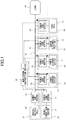
- FIG. 1 is an overall configuration diagram illustrating a direct current bus control system according to this embodiment.
- the direct current bus control system illustrated in FIG. 1 includes, as an input power supply, a photovoltaic power generation system 10 and a wind-power generation system 20, which are renewable energy power supply systems. These power generation systems 10 and 20 are connected in parallel, and the output sides of the power generation systems 10 and 20 are connected to the direct current bus 70.
- the photovoltaic power generation system 10 includes a photovoltaic cell 11 and a power converter 12, and the wind-power generation system 20 includes a wind-power generator 21 and a power converter 22.
- the input power supply is not particularly limited.
- the input power supply may be a power supply system that uses wave power or geothermal energy other than those described above, or may be a power supply system such as hydropower (small hydropower) power generation, tidal power generation, marine current power generation, ocean thermal energy power generation, or the like.
- the input power supply may also be a combination of those power supply systems including those listed above.
- the number of power supply systems connected in parallel with each other is not particularly limited.
- the direct current bus 70 is connected to the main stabilizing device 30 and the sub-stabilizing devices 40, 50, and 60, and is also connected to the load 90.
- the main stabilizing device 30 sets a variable bus voltage target value within a predetermined permissible range around a reference bus voltage (i.e., a reference voltage of the direct current bus 70), and controls charging and discharging of the power storage device 31 by operating the power converter 32 so that the output voltage at the side of the direct current bus 70 matches the bus voltage target value.
- a reference bus voltage i.e., a reference voltage of the direct current bus 70
- the sub-stabilizing device 40 calculates an input-&-output current target value on the basis of a difference between a charge-&-discharge threshold value and the voltage of the direct current bus, and controls charging and discharging of the power storage device 41 by operating the power converter 42 so that an input-&-output current matches the input-&-output current target value.
- the power storage devices 31 and 41 are, for example, a battery (secondary battery), an electric double layer capacitor, a capacitor, a flywheel, a redox flow battery, or the like.
- the power converter 32 and 42 are, for example, an isolated DC-DC converter or a chopper, and can bidirectionally pass direct current power as indicated by arrows.
- the sub-stabilizing device 50 causes the power converter 52 to perform DC-DC conversion so that the input-&-output current matches the input-&-output current target value calculated based on the difference between the charge threshold value and the voltage of the direct current bus, thus supplying direct current power to the water electrolysis cell 51 (a kind of charge operation) to electrolyze water to generate hydrogen gas and oxygen gas.
- the sub-stabilizing device 60 causes the power converter 62 to perform DC-DC conversion so that the input-&-output current matches the input-&-output current target value calculated based on the difference between the discharge threshold value and the voltage of the direct current bus.
- substitutes for the water electrolysis cell 51 include means for electrochemically producing C-H bonds (CH 4 , C 2 H 4 , and the like) and alcohol by reducing carbon dioxide and means for producing ammonia by reducing nitrogen.
- substitutes for the fuel cell 61 include a fuel cell using alcohol and power generation means that rotates turbines and the like by combusting chemical substances (hydrogen, substances having C-H bonds, alcohol, ammonia, or the like).
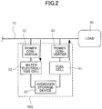
- FIG. 2 is another example of configuration of the sub-stabilizing device.
- the sub-stabilizing devices 50 and 60 explained above may be a sub-stabilizing device 50A of an integrated structure in which the hydrogen storage device 53 is shared.
- the power storage devices 31 and 41 are capable of charging and discharging direct current power.
- the water electrolysis cell 51 (and the hydrogen storage device 53 of FIG. 2 ) can convert direct current power into gas and accumulate the generated gas, and the fuel cell 61 (and the same hydrogen storage device 53) can perform power generation operation for converting the gas into direct current power.
- the power storage devices 31 and 41 constitute a charge-&-discharge element.
- the water electrolysis cell 51 (and the hydrogen storage device 53) constitute a charge element.
- the fuel cell 61 (and the hydrogen storage device 53) constitute a discharge element.
- each of the stabilizing devices 30, 40, 50, and 60 can be deemed as a power buffer for exchanging direct current power with the direct current bus 70 according to the operation of the power converters 32, 42, 52, and 62.
- the main stabilizing device 30 and the sub-stabilizing device 40 are power buffers having charge-&-discharge function.
- the sub-stabilizing device 50 is a power buffer having a charge function.
- the sub-stabilizing device 60 is a power buffer having a discharge function.
- Only one main stabilizing device 30 having a setting function for setting the bus voltage target value may be provided. Conversely, any required number of sub-stabilizing devices may be provided according to the number of power supply systems connected in parallel and the power demanded by the load 90.
- the monitoring-&-instruction device 80 collects state information (e.g., a voltage, a current, a temperature, and the like) about each of the power generation systems 10 and 20, the main stabilizing device 30, and the sub-stabilizing devices 40, 50, and 60 to monitor the state and the operation, and generates an operation instruction (start and stop instructions and the like), a charge-&-discharge threshold value instruction, and the like, on the basis of these monitor results.
- state information e.g., a voltage, a current, a temperature, and the like
- an operation instruction start and stop instructions and the like
- a charge-&-discharge threshold value instruction e.g., a charge-&-discharge threshold value instruction, and the like
- the load 90 may be a direct current load such as a direct current electric motor and the like, or a DC/AC converter converting direct current power into alternating current power and an alternating current load therefor.
- Alternating current power system may be connected to the direct current bus 70 via a DC/AC converter.
- the photovoltaic power generation system 10 and the wind-power generation system 20 have a common function in that both convert a power generated using renewable energy into direct current power with the power converters 12 and 22 and supply the direct current power to the direct current bus 70. Therefore, the photovoltaic power generation system 10 will be described below as an example.
- FIG. 3 is a block diagram illustrating an example of configuration of the power converter 12 in the photovoltaic power generation system 10.
- This power converter 12 includes a DC-DC conversion unit 12A and a control circuit 12B.
- the DC-DC conversion unit 12A converts a direct current output voltage of the photovoltaic cell 11 into a direct current voltage of a predetermined magnitude according to an operation of a semiconductor switching device, and outputs the converted direct current voltage to the direct current bus 70.
- the DC-DC conversion unit 12A is constituted by a boost chopper.
- a voltage detector 12a and a current detector 12b detect a voltage and a current, respectively, which are output from the photovoltaic cell 11, and these detection values are input into the MPPT control unit 12c.
- the MPPT control unit 12c searches a maximum output point of the photovoltaic cell 11 based on the hill climbing method and the like to output the maximum output point to the voltage-&-current control unit 12d.
- the voltage-&-current control unit 12d generates a driving pulse according to PWM (pulse width modulation) control and the like, and sends the driving pulse to a driving circuit 12e.
- the driving circuit 12e turns ON and OFF a semiconductor switching device of the DC-DC conversion unit 12A on the basis of the driving pulse.
- the voltage of the direct current bus 70 is detected by a voltage detector 12f, and this bus voltage detection value and a bus voltage target value sent from the main stabilizing device 30 described later are input into a comparison unit 12g.
- the comparison unit 12g generates a control signal corresponding to a deviation between the bus voltage detection value and the bus voltage target value and outputs the control signal to the voltage-&-current control unit 12d.
- the voltage-&-current control unit 12d calculates a driving pulse for causing the bus voltage detection value to match the bus voltage target value on the basis of the above control signal. For example, in a case where the bus voltage detection value exceeds the bus voltage target value, the voltage-&-current control unit 12d performs control operation (including operation stop) so as to decrease the output voltage of the DC-DC conversion unit 12A.
- FIG. 4 is a block diagram illustrating an example of configuration of the power converter 32 in the main stabilizing device 30.
- This power converter 32 includes a DC-DC conversion unit 32A and a control circuit 32B.
- the DC-DC conversion unit 32A has a function of controlling charging and discharging of the power storage device 31 by bidirectionally passing direct current power between the direct current bus 70 and the power storage device 31.
- the DC-DC conversion unit 32A is constituted by an isolated DC-DC converter, a chopper, and the like having a semiconductor switching device.
- the power storage device 31 is provided with a sensor 31a for detecting a voltage, a current, and a temperature.
- control circuit 32B The configuration of the control circuit 32B is as follows.
- the voltage detector 32a detects the voltage of the direct current bus 70, and the bus voltage target value calculation unit 32b calculates a bus voltage target value according to the power storage amount index of the power storage device 31.
- the method for calculating the bus voltage target value will be explained later.
- An example of the power storage amount index is a state of charge (SOC) obtained by integrating charge-&-discharge currents of the power storage device 31 detected by the sensor 31a.
- SOC state of charge
- a subtractor 32c calculates a difference between the bus voltage target value and the bus voltage detection value, and outputs this voltage difference to the charge-&-discharge control unit 32d.
- the charge-&-discharge control unit 32d receives the voltage, the current, and the temperature of the power storage device 31, and also receives the charge-&-discharge threshold value. In view of input information, the charge-&-discharge control unit 32d generates a driving pulse by performing PWM control and the like so that the bus voltage detection value matches the bus voltage target value.
- a driving circuit 32e turns on and off the semiconductor switching device of the DC-DC conversion unit 32A according to the driving pulse. In this manner, the DC-DC conversion unit 32A controls charging and discharging of the power storage device 31 to cause the bus voltage detection value to match the bus voltage target value.
- the charge-&-discharge threshold value of the power storage device 31 may be set by the control circuit 32B, or may be received as an instruction from the monitoring-&-instruction device 80 of FIG. 1 .
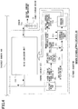
- FIG. 5 is a block diagram illustrating an example of configuration of the power converter 42 in the sub-stabilizing device 40 of FIG. 1 .
- This power converter 42 includes a DC-DC conversion unit 42A and a control circuit 42B.
- the power converter 42 has a function similar to the power converter 32 of FIG. 4 in that the power converter 42 bidirectionally passes direct current power between the direct current bus 70 and the power storage device 41.
- the power storage device 41 is provided with a sensor 41a for detecting a voltage, a current, and a temperature.
- the control circuit 42B includes a voltage detector 42a, a comparison unit 42b, a subtractor 42c, a charge-&-discharge control unit 42d, and a driving circuit 42e.
- the power converter 42 illustrated in FIG. 5 is different from the power converter 32 of FIG. 4 in the following features.
- the charge-&-discharge control unit 42d calculates an input-&-output current target value on the basis of a difference between a charge-&-discharge threshold value and the bus voltage detection value. Further, the charge-&-discharge control unit 42d controls charging and discharging of the power storage device 41 so that the input-&-output current of the DC-DC conversion unit 42A matches the input-&-output current target value.
- the charge-&-discharge threshold value may be a threshold value (a charge threshold value and a discharge threshold value) of charging and discharging of the power storage device 41.
- the input-&-output current target value may be determined in accordance with a difference between this threshold value and the voltage of the direct current bus 70.
- the comparison unit 42b provided in the control circuit 42B compares the charge-&-discharge threshold value of the power storage device 41 with the bus voltage detection value, and controls operation of the charge-&-discharge control unit 42d by outputting a charge instruction or a discharge instruction in accordance with a relationship in magnitude between the charge threshold value or the discharge threshold value and the bus voltage detection value.
- the charge-&-discharge threshold value may be set by the control circuit 42B, or may be received as an instruction from the monitoring-&-instruction device 80.
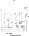
- FIG. 6 is a block diagram illustrating an example of configuration of the power converter 52 in the sub-stabilizing device 50.
- This power converter 52 includes a DC-DC conversion unit 52A and a control circuit 52B.
- the DC-DC conversion unit 52A has a function of converting direct current power of the direct current bus 70 to a predetermined level and supplying the converted direct current power to the water electrolysis cell 51.
- the DC-DC conversion unit 52A is constituted by an isolated DC-DC converter, a chopper, and the like having a semiconductor switching device.
- the water electrolysis cell 51 performs an operation electrolyzing water using the direct current power supplied from the DC-DC conversion unit 52A and storing the generated hydrogen gas in an external storage device (not illustrated). In other words, the water electrolysis cell 51 performs a kind of charge operation.
- the control circuit 52B controlling the DC-DC conversion unit 52A is configured in a manner substantially similar to the control circuit 42B of FIG. 5 .
- a voltage detector 52a detects a voltage of the direct current bus 70, and a subtractor 52c calculates a difference between a charge threshold value and the bus voltage detection value, and this voltage difference is input to the charge control unit 52d.
- the bus voltage detection value and the charge threshold value are also input to a comparison unit 52b.
- the comparison unit 52b outputs a charge instruction to the charge control unit 52d.
- the charge threshold value corresponds to a voltage at which the water electrolysis cell 51 starts electrolysis.
- the charge threshold value is a threshold value for charging of the water electrolysis cell 51.
- the charge control unit 52d calculates an input-&-output current target value on the basis of the voltage difference received from the subtractor 52c, generates a driving pulse as a charge instruction so that the input-&-output current of the DC-DC conversion unit 52A matches the input-&-output current target value, and outputs the generated driving pulse to a driving circuit 52e.
- the driving circuit 52e turns on and off a semiconductor switching device in the DC-DC conversion unit 52A in accordance with the driving pulse, thus supplying direct current power to the water electrolysis cell 51 and electrolyzing water.
- the DC-DC conversion unit 52A controls the direct current power supplied to the water electrolysis cell 51 according to the above operation, the DC-DC conversion unit 52A operates so as to cause the input-&-output current to match the input-&-output current target value.
- the power generation operation performed by the power generation operation by the fuel cell 61 may be deemed as a discharge operation, and accordingly, the water electrolysis cell 51, the charge threshold value, and the charge control unit 52d of the sub-stabilizing device 50 illustrated in FIG. 6 may be read as the fuel cell 61, a discharge threshold value, and a discharge control unit, respectively.
- the discharge threshold value corresponds to a start voltage of power generation by the fuel cell 61.
- the sub-stabilizing device 60 When the bus voltage detection value falls below the discharge threshold value, the sub-stabilizing device 60 outputs a driving pulse corresponding to the discharge instruction to the discharge control unit to cause the DC-DC conversion unit to perform operation to supply the power generated by the fuel cell 61 to the direct current bus 70 via the DC-DC conversion unit.
- the DC-DC conversion unit controls the power to be generated by the fuel cell 61 according to the above operation, the DC-DC conversion unit operates so as to cause the input-&-output current to match the input-&-output current target value.
- the water electrolysis cell 51 and the fuel cell 61 are also provided with sensors for detecting voltages, currents, and temperatures, and these detection values are input to the charge control unit 52d and the discharge control unit. For the sake of convenience, the sensors are not illustrated.
- the charge threshold value and the discharge threshold value may be set by a corresponding control circuit, or may be received as an instruction from the monitoring-&-instruction device 80.
- the power converters 12, 32, 42, and 52 illustrated in FIG. 3 to FIG. 6 , and in particular, the configuration and the operation of the control circuits 12B, 32B, 42B, and 52B, are merely examples, and are not intended to limit the technical scope of the present invention any way, and it is to be understood that a configuration different from the above may be adopted.
- FIG. 7 is a conceptual diagram schematically illustrating a relationship between: charge-&-discharge powers of the power storage device 41 of the sub-stabilizing device 40, an input power of the water electrolysis cell 51 of the sub-stabilizing device 50, and an output power of the fuel cell 61 of the sub-stabilizing device 60; and the voltage of the direct current bus 70.
- the width of each triangular symbol in FIG. 7 indicates the magnitude of the power. The wider the width of the triangular symbol is, the larger the value of the power is.
- FIG. 7 illustrates an example in which the input power supply is a renewable energy power supply system.
- the renewable energy power supply system is, for example, the photovoltaic power generation system 10 and/or the wind-power generation system 20 of FIG. 1 .
- the charge-&-discharge operation of each unit is controlled in accordance with the voltage of the direct current bus 70 to which the generated power is supplied and the charge-&-discharge threshold values and the like of the power storage device 41, the water electrolysis cell 51, and the fuel cell 61.
- the higher the bus voltage is relative to the charge threshold value of the water electrolysis cell 51 the larger the charge power supplied to the water electrolysis cell 51 becomes, and the lower the bus voltage is relative to the discharge threshold value of the fuel cell 61, the larger the discharge power generated by the fuel cell 61 becomes.
- a case (b) for the power storage device 41 relates to a case where the charge threshold value and the discharge threshold value are set to values lower than the case (a) according to a reference bus voltage.
- a case (c) relates to a case where the charge threshold value and the discharge threshold value are set to values higher than the case (a).
- a similar setting change operation of the threshold value can also be performed for the charge threshold value of the water electrolysis cell 51 and the discharge threshold value of the fuel cell 61.
- the direct current power exchanged between the direct current bus 70 and the sub-stabilizing devices 40, 50, and 60 can be individually adjusted by controlling the charge-&-discharge operation by changing the charge threshold values and the discharge threshold values of the power storage device 41, the water electrolysis cell 51, and the fuel cell 61.
- the operation for the power buffer can be more finely controlled in each of the sub-stabilizing devices 40, 50, and 60.
- the changes of the charge threshold values and the discharge threshold values can be performed on the basis of an instruction from the monitoring-&-instruction device 80 or by the power converters 42, 52, and 62.
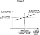
- FIGs. 8A and 8B are drawings for explaining an operation of the main stabilizing device 30.
- the main stabilizing device 30 passes direct current power between the direct current bus 70 and the power storage device 31, and controls charging and discharging of the power storage device 31.
- the control circuit 32B in the power converter 32 sets a bus voltage target value on the basis of the power storage amount index (for example, a state of charge) of the power storage device 31 according to characteristics as illustrated in FIG. 8B , for example.
- this bus voltage target value is set to a higher value as the power storage amount index is larger, and is set to a lower value as the power storage amount index is smaller.
- the control circuit 32B controls the DC-DC conversion unit 32A so as to cause the bus voltage detection value to match this bus voltage target value.
- FIGs. 9A and 9B are drawings for explaining operations of the sub-stabilizing devices 40 and 50.
- the power converter 42 of the sub-stabilizing device 40 charges the power storage device 41 by using the direct current power of the direct current bus 70, and the power converter 52 of the sub-stabilizing device 50 supplies the direct current power of the direct current bus 70 to the water electrolysis cell 51 to electrolyze water.
- the charge characteristics in this case are as illustrated in FIG. 9B .
- Each of the power converters 42 and 52 is controlled so that, the higher the voltage of the direct current bus 70 is relative to the charge threshold value of the power storage device 41 or the water electrolysis cell 51, the larger the charge current becomes.
- FIGs. 10A and 10B are drawings for explaining operations of the sub-stabilizing devices 40 and 60.
- the power converter 42 of the sub-stabilizing device 40 causes the power storage device 41 to discharge and supply direct current power to the direct current bus 70
- the power converter 62 of the sub-stabilizing device 60 causes the fuel cell 61 to perform power generation operation to supply direct current power to the direct current bus 70.
- Each of the power converters 42 and 62 is controlled so that, the lower the voltage of the direct current bus 70 is relative to the discharge threshold value of the power storage device 41 or the fuel cell 61, the larger the discharge current becomes.
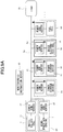
- FIG. 11 illustrates a model of a direct current bus control system used for simulation, and includes the photovoltaic power generation system 10, the main stabilizing device 30, the sub-stabilizing devices 50 and 60, the direct current bus 70, and the load 90.
- the power converter 12 of the photovoltaic power generation system 10 is assumed to perform MPPT (maximum power point tracking) control for changing current drawn and voltage with every 0.1 [sec].
- the power converter 32 of the main stabilizing device 30 measures a charge-&-discharge current of the power storage device 31 to derive an estimated power storage amount index with every 0.1 [sec].
- the bus voltage target value is calculated on the basis of this estimated power storage amount index, a reference power storage amount index, and a reference bus voltage.
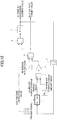
- FIG. 12 is a block diagram illustrating a main part of the main stabilizing device 30.
- the configuration illustrated in FIG. 12 includes a pulse generator 1, an estimated power storage amount index calculation unit 2, subtractors 3 and 6, a gain multiplier 4, an adder 5, and a PID (proportional integral derivative) controller 7.
- K1 is a constant corresponding to the reference power storage amount index
- K2 is a constant corresponding to the reference bus voltage.
- FIG. 13 is a block diagram illustrating a main part of the sub-stabilizing device 50 used for simulation.
- the configuration as illustrated in FIG. 13 includes: a subtractor 9 configured to derive a difference between the bus voltage detection value and the reference bus voltage; a PID controller 110 configured to operate so as to eliminate the difference; and a memory 111, and calculates a current to be output to the water electrolysis cell 51.
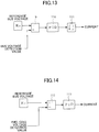
- FIG. 14 is a block diagram illustrating a main part of the sub-stabilizing device 60 used for simulation.
- the configuration as illustrated in FIG. 14 includes: a subtractor 112 configured to derive a difference between the reference bus voltage and the voltage detection value of the fuel cell 61; and a PID controller 113 configured to operate so as to eliminate the difference, and calculates a power generation current by the fuel cell 61.
- FIG. 15 and FIG. 16 are waveform diagrams of voltages and currents of respective units, showing a result of a simulation.
- FIG. 15 (a) indicates a voltage of the photovoltaic cell 11, (b) indicates a current of the photovoltaic cell 11, (c) indicates a bus voltage, and (d) indicates a load current.
- FIG. 16 (a) indicates a voltage of the power storage device 31, (b) indicates a current of the power storage device 31, (c) indicates a current of the water electrolysis cell 51, and (d) indicates a current of the fuel cell 61 (including a leakage current in a normal state).
- the bus voltage target value in FIG. 15 (c) was calculated by the block diagram of the main stabilizing device 30 as illustrated in FIG. 12 .
- the bus voltage detection value closely followed the bus voltage target value.
- the main stabilizing device 30 having the power storage device 31, the sub-stabilizing device 50 having the water electrolysis cell 51, and the sub-stabilizing device 60 having the fuel cell 61 are operated as power buffers by autonomously performing charge operation or discharge operation in accordance with the relationship in magnitude between the corresponding charge-&-discharge threshold value and the bus voltage.
- the bus voltage detection value was maintained in a predetermined permissible range (in a range of approximately from 379.7 [V] to 380.5 [V]).
- the bus voltage detection value closely followed the bus voltage target value, and was maintained substantially constantly within the predetermined permissible range.
- the power fluctuation of the direct current bus 70 substantially matches the change in the current value. Therefore, in the direct current bus control system according to the present invention, with the control of voltage performed by the main stabilizing device 30 and the control of the current performed by the sub-stabilizing devices 50 and 60, the power fluctuation of the direct current bus 70 can be controlled.
- a quickly responding sub-stabilizing device operates preferentially to absorb the power fluctuation of the direct current bus 70, and the remaining sub-stabilizing devices may not operate. Such a situation is not desirable from the viewpoint of equalizing the operations of the devices.
- a problem similar to the above may occur in a case where multiple sub-stabilizing devices having discharge functions (for example, sub-stabilizing devices having fuel cells) are connected to the direct current bus 70 or in a case where multiple sub-stabilizing devices having charge-&-discharge functions (for example, sub-stabilizing devices having power storage devices) are connected to the direct current bus 70.
- a Droop control for reducing the output voltage according to the increase of the output current may be applied to multiple sub-stabilizing devices having the same function (a charge function or a discharge function) to adjust the Droop rates so that the load (e.g., a utilization ratio or operation responsibility) may be distributed to the devices with a predetermined ratio.
- the load e.g., a utilization ratio or operation responsibility
- each sub-stabilizing device in view of a reaction responsiveness, a charge capacity, and the like of each sub-stabilizing device, it may be considered to employ a method of operating with prioritization of charge powers and discharge powers, such as, for example, causing a certain sub-stabilizing device to operate in a state close to a fully charged state and causing another sub-stabilizing device to operate in a substantially completely discharged state.
Landscapes
- Engineering & Computer Science (AREA)
- Power Engineering (AREA)
- Charge And Discharge Circuits For Batteries Or The Like (AREA)
- Supply And Distribution Of Alternating Current (AREA)
- Dc-Dc Converters (AREA)
- Direct Current Feeding And Distribution (AREA)
- Control Of Eletrric Generators (AREA)
- Remote Monitoring And Control Of Power-Distribution Networks (AREA)
- Control Of Multiple Motors (AREA)
Applications Claiming Priority (2)
| Application Number | Priority Date | Filing Date | Title |
|---|---|---|---|
| JP2017223808 | 2017-11-21 | ||
| PCT/JP2018/043064 WO2019103059A1 (fr) | 2017-11-21 | 2018-11-21 | Système de commande de bus à courant continu |
Publications (2)
| Publication Number | Publication Date |
|---|---|
| EP3716435A1 true EP3716435A1 (fr) | 2020-09-30 |
| EP3716435A4 EP3716435A4 (fr) | 2021-04-07 |
Family
ID=66630534
Family Applications (1)
| Application Number | Title | Priority Date | Filing Date |
|---|---|---|---|
| EP18882169.8A Pending EP3716435A4 (fr) | 2017-11-21 | 2018-11-21 | Système de commande de bus à courant continu |
Country Status (7)
| Country | Link |
|---|---|
| US (1) | US11133673B2 (fr) |
| EP (1) | EP3716435A4 (fr) |
| JP (1) | JP6923231B2 (fr) |
| KR (1) | KR102444737B1 (fr) |
| CN (2) | CN117833190A (fr) |
| AU (1) | AU2018373453B2 (fr) |
| WO (1) | WO2019103059A1 (fr) |
Families Citing this family (27)
| Publication number | Priority date | Publication date | Assignee | Title |
|---|---|---|---|---|
| US11870249B2 (en) * | 2018-05-24 | 2024-01-09 | Hamilton Sundstrand Corporation | Electrical power system including energy storage modules and shared system controller |
| JP7390545B2 (ja) * | 2019-06-28 | 2023-12-04 | パナソニックIpマネジメント株式会社 | 蓄電池システム、制御方法、及びプログラム |
| KR102245969B1 (ko) * | 2019-11-21 | 2021-04-29 | 연세대학교 산학협력단 | 태양광 발전 시스템의 일정 출력 제어를 위한 장치 및 방법 |
| JP2021141761A (ja) * | 2020-03-06 | 2021-09-16 | パナソニックIpマネジメント株式会社 | 充放電システム、充放電方法及びプログラム |
| JPWO2021200902A1 (fr) * | 2020-03-31 | 2021-10-07 | ||
| CN113541167B (zh) | 2020-04-20 | 2024-10-18 | 台达电子企业管理(上海)有限公司 | 燃料电池供能系统及基于其的能量调节方法 |
| WO2021261094A1 (fr) * | 2020-06-22 | 2021-12-30 | 国立研究開発法人理化学研究所 | Système de commande de bus à courant continu |
| CN115917903A (zh) | 2020-06-30 | 2023-04-04 | 古河电气工业株式会社 | 电力变换器、电力变换器的控制方法、电力系统、电力系统的控制方法及程序 |
| CN115699493A (zh) | 2020-06-30 | 2023-02-03 | 古河电气工业株式会社 | 电力变换器、电力变换器的控制方法、电力系统、电力系统的控制方法及程序 |
| WO2022030299A1 (fr) | 2020-08-06 | 2022-02-10 | 古河電気工業株式会社 | Convertisseur de courant, procédé de commande de convertisseur de courant, système d'alimentation, procédé de commande de système d'alimentation et programme |
| WO2022059617A1 (fr) | 2020-09-15 | 2022-03-24 | 古河電気工業株式会社 | Convertisseur d'énergie électrique, procédé de commande de convertisseur d'énergie électrique, système d'alimentation électrique, procédé de commande de système d'alimentation électrique, et programme |
| JP7553793B2 (ja) | 2020-10-07 | 2024-09-19 | 日新電機株式会社 | 制御装置 |
| CN112202160B (zh) * | 2020-10-20 | 2022-06-03 | 国网四川省电力公司电力科学研究院 | 一种直挂母线式储能控制系统及控制方法 |
| JP7510850B2 (ja) | 2020-11-05 | 2024-07-04 | 株式会社日立製作所 | Dcグリッドシステム、制御装置、制御方法 |
| WO2022107583A1 (fr) | 2020-11-20 | 2022-05-27 | 古河電気工業株式会社 | Système d'alimentation et procédé de commande d'un système d'alimentation |
| JPWO2022130802A1 (fr) | 2020-12-17 | 2022-06-23 | ||
| JP7509050B2 (ja) | 2021-02-19 | 2024-07-02 | トヨタ自動車株式会社 | 発電制御装置、車両、制御方法及び制御プログラム |
| CN113589076B (zh) * | 2021-07-23 | 2024-04-02 | 西门子(中国)有限公司 | 飞轮储能中电机负载的模拟方法和计算机可读介质 |
| IT202100019952A1 (it) * | 2021-07-27 | 2023-01-27 | Hera S P A | Impianto per la produzione e la gestione di energia rinnovabile per aree urbane, industriali e simili |
| JPWO2023054406A1 (fr) * | 2021-09-29 | 2023-04-06 | ||
| EP4184625B1 (fr) * | 2021-11-11 | 2024-08-07 | Bloom Energy Corporation | Système de pile à combustible hybride pour le suivi et la sauvegarde de charge dans un micro-réseau et son procédé de fonctionnement |
| WO2023106406A1 (fr) | 2021-12-10 | 2023-06-15 | 国立研究開発法人理化学研究所 | Système de commande de bus à courant continu |
| US20230344222A1 (en) * | 2022-04-21 | 2023-10-26 | Dc Systems B.V. | Droop control in a dc operated system |
| WO2023210123A1 (fr) * | 2022-04-28 | 2023-11-02 | 株式会社村田製作所 | Unité de batterie et système d'alimentation électrique |
| WO2024034194A1 (fr) * | 2022-08-09 | 2024-02-15 | 株式会社フジタ | Système de commande de puissance |
| EP4366114A1 (fr) * | 2022-11-07 | 2024-05-08 | H2-Greenforce, BV | Installation de production autonome et continue d'hydrogène |
| WO2024150648A1 (fr) * | 2023-01-10 | 2024-07-18 | 古河電気工業株式会社 | Système électrique, dispositif de commande et procédé de commande |
Family Cites Families (18)
| Publication number | Priority date | Publication date | Assignee | Title |
|---|---|---|---|---|
| JPS58919B2 (ja) | 1973-09-14 | 1983-01-08 | マツナカ シゲオ | ヒヨウリヒタイシヨウブツピン ノ ヒヨウリケンシユツソウチ |
| JP4191625B2 (ja) * | 2004-02-05 | 2008-12-03 | マイウェイ技研株式会社 | 分散電源システム |
| JP4167215B2 (ja) * | 2004-10-27 | 2008-10-15 | 株式会社日立製作所 | 直流配電システムの制御装置及び変換器制御装置 |
| KR101490547B1 (ko) * | 2008-11-19 | 2015-02-05 | 도시바 미쓰비시덴키 산교시스템 가부시키가이샤 | 출력 전력 제어 장치 |
| US8866334B2 (en) * | 2010-03-02 | 2014-10-21 | Icr Turbine Engine Corporation | Dispatchable power from a renewable energy facility |
| JP5028517B2 (ja) * | 2010-10-26 | 2012-09-19 | シャープ株式会社 | 直流給電システム |
| US20140285010A1 (en) * | 2011-05-24 | 2014-09-25 | D. Kevin CAMERON | System and method for integrating and managing demand/response between alternative energy sources, grid power, and loads |
| WO2013118336A1 (fr) | 2012-02-08 | 2013-08-15 | 三菱電機株式会社 | Dispositif de conversion de puissance |
| WO2013145658A1 (fr) * | 2012-03-26 | 2013-10-03 | パナソニック株式会社 | Appareil de commande de charge/décharge, système de stockage d'électricité et procédé de commande de charge/décharge |
| CN103548235B (zh) * | 2012-03-26 | 2017-09-08 | 松下知识产权经营株式会社 | 充放电控制装置及充放电控制方法 |
| JP5989478B2 (ja) * | 2012-09-20 | 2016-09-07 | シャープ株式会社 | 蓄電装置および直流システム |
| JP2015130732A (ja) * | 2014-01-07 | 2015-07-16 | Tdk株式会社 | 電力安定化装置 |
| CN103762610B (zh) * | 2014-01-07 | 2016-03-02 | 中国科学院电工研究所 | 基于主从下垂控制的分布式储能系统 |
| JP2015201973A (ja) * | 2014-04-08 | 2015-11-12 | 日本電信電話株式会社 | 給電システム |
| JP6502758B2 (ja) | 2015-06-15 | 2019-04-17 | 川崎重工業株式会社 | 直流安定化電源システム |
| JP6731607B2 (ja) * | 2016-03-25 | 2020-07-29 | パナソニックIpマネジメント株式会社 | 電力変換システム |
| JP6780311B2 (ja) | 2016-06-14 | 2020-11-04 | 富士ゼロックス株式会社 | 搬送装置、定着装置及び画像形成装置 |
| CN106505616B (zh) * | 2016-11-17 | 2018-12-18 | 华北电力大学(保定) | 一种直流配电网直流电压的调节方法 |
-
2018
- 2018-11-21 CN CN202410081512.9A patent/CN117833190A/zh active Pending
- 2018-11-21 EP EP18882169.8A patent/EP3716435A4/fr active Pending
- 2018-11-21 JP JP2019555345A patent/JP6923231B2/ja active Active
- 2018-11-21 WO PCT/JP2018/043064 patent/WO2019103059A1/fr unknown
- 2018-11-21 AU AU2018373453A patent/AU2018373453B2/en active Active
- 2018-11-21 CN CN201880074799.5A patent/CN111448733A/zh active Pending
- 2018-11-21 KR KR1020207014503A patent/KR102444737B1/ko active IP Right Grant
-
2020
- 2020-05-20 US US16/878,725 patent/US11133673B2/en active Active
Also Published As
| Publication number | Publication date |
|---|---|
| EP3716435A4 (fr) | 2021-04-07 |
| CN117833190A (zh) | 2024-04-05 |
| WO2019103059A1 (fr) | 2019-05-31 |
| CN111448733A (zh) | 2020-07-24 |
| US20200280183A1 (en) | 2020-09-03 |
| AU2018373453A1 (en) | 2020-06-11 |
| KR20200090163A (ko) | 2020-07-28 |
| JPWO2019103059A1 (ja) | 2020-11-19 |
| JP6923231B2 (ja) | 2021-08-18 |
| KR102444737B1 (ko) | 2022-09-19 |
| US11133673B2 (en) | 2021-09-28 |
| AU2018373453B2 (en) | 2021-12-09 |
Similar Documents
| Publication | Publication Date | Title |
|---|---|---|
| US11133673B2 (en) | Direct current bus control system | |
| Sanjeev et al. | Peak energy management using renewable integrated DC microgrid | |
| JP5641144B2 (ja) | 電力変換装置 | |
| JP5929258B2 (ja) | 電力供給システムおよび電源装置 | |
| US9450451B2 (en) | Photovoltaic generation system and power feeding system | |
| EP2822163A1 (fr) | Système d'alimentation | |
| US9391537B2 (en) | Photovoltaic system and power supply system | |
| JP2015220889A (ja) | 電力供給システム | |
| CN106786803A (zh) | 独立运行光伏发电系统供大于需时的一种无损功率平衡法 | |
| US20130056986A1 (en) | Wind power generation system and method for controlling the same | |
| WO2021261094A1 (fr) | Système de commande de bus à courant continu | |
| KR20190101672A (ko) | 최대전력점 추종 제어를 위한 태양광 발전 시스템 | |
| JP2016103915A (ja) | 蓄電池システムおよび蓄電方法 | |
| JP2015192549A (ja) | 電力変換装置及び電力変換方法 | |
| WO2021200902A1 (fr) | Système de commande de bus à courant continu | |
| JP6256983B2 (ja) | 蓄電池付きパワーコンディショナ | |
| JP5172613B2 (ja) | 太陽光発電装置および太陽光発電システム | |
| WO2021229652A1 (fr) | Système d'électrolyse de l'eau et dispositif de commande de courant électrique | |
| WO2023054406A1 (fr) | Système de commande de bus à courant continu | |
| WO2023106406A1 (fr) | Système de commande de bus à courant continu | |
| JP2006067673A (ja) | 電源装置 | |
| WO2011118771A1 (fr) | Système de charge/décharge | |
| Kbidi et al. | Energy Management System in Micro-Grid with Storage and Hydrogen Production | |
| KR102713751B1 (ko) | 전압제어를 하는 일체형 전력공급장치 | |
| JP2016054583A (ja) | 蓄電池システム |
Legal Events
| Date | Code | Title | Description |
|---|---|---|---|
| STAA | Information on the status of an ep patent application or granted ep patent |
Free format text: STATUS: THE INTERNATIONAL PUBLICATION HAS BEEN MADE |
|
| PUAI | Public reference made under article 153(3) epc to a published international application that has entered the european phase |
Free format text: ORIGINAL CODE: 0009012 |
|
| STAA | Information on the status of an ep patent application or granted ep patent |
Free format text: STATUS: REQUEST FOR EXAMINATION WAS MADE |
|
| 17P | Request for examination filed |
Effective date: 20200519 |
|
| AK | Designated contracting states |
Kind code of ref document: A1 Designated state(s): AL AT BE BG CH CY CZ DE DK EE ES FI FR GB GR HR HU IE IS IT LI LT LU LV MC MK MT NL NO PL PT RO RS SE SI SK SM TR |
|
| AX | Request for extension of the european patent |
Extension state: BA ME |
|
| DAV | Request for validation of the european patent (deleted) | ||
| DAX | Request for extension of the european patent (deleted) | ||
| RIN1 | Information on inventor provided before grant (corrected) |
Inventor name: SUGIYAMA, MASAKAZU Inventor name: TSUNO, KATSUHIKO Inventor name: FUJII, KATSUSHI Inventor name: WADA, SATOSHI Inventor name: YAMASHITA, DAIJI Inventor name: KOIKE, KAYO |
|
| A4 | Supplementary search report drawn up and despatched |
Effective date: 20210304 |
|
| RIC1 | Information provided on ipc code assigned before grant |
Ipc: H02J 7/35 20060101ALI20210226BHEP Ipc: H02J 1/12 20060101ALI20210226BHEP Ipc: H02J 3/38 20060101ALI20210226BHEP Ipc: H02J 3/32 20060101ALI20210226BHEP Ipc: H02J 1/00 20060101AFI20210226BHEP Ipc: H02J 7/10 20060101ALI20210226BHEP |