EP3715877B1 - Buskurzschlussdetektionsverfahren, schaltung, speichermedium und prozessor - Google Patents
Buskurzschlussdetektionsverfahren, schaltung, speichermedium und prozessor Download PDFInfo
- Publication number
- EP3715877B1 EP3715877B1 EP18880907.3A EP18880907A EP3715877B1 EP 3715877 B1 EP3715877 B1 EP 3715877B1 EP 18880907 A EP18880907 A EP 18880907A EP 3715877 B1 EP3715877 B1 EP 3715877B1
- Authority
- EP
- European Patent Office
- Prior art keywords
- circuit
- bus
- charge
- weak electricity
- short
- Prior art date
- Legal status (The legal status is an assumption and is not a legal conclusion. Google has not performed a legal analysis and makes no representation as to the accuracy of the status listed.)
- Active
Links
Images

Classifications
-
- G—PHYSICS
- G01—MEASURING; TESTING
- G01R—MEASURING ELECTRIC VARIABLES; MEASURING MAGNETIC VARIABLES
- G01R31/00—Arrangements for testing electric properties; Arrangements for locating electric faults; Arrangements for electrical testing characterised by what is being tested not provided for elsewhere
- G01R31/50—Testing of electric apparatus, lines, cables or components for short-circuits, continuity, leakage current or incorrect line connections
- G01R31/52—Testing for short-circuits, leakage current or ground faults
-
- H—ELECTRICITY
- H02—GENERATION; CONVERSION OR DISTRIBUTION OF ELECTRIC POWER
- H02H—EMERGENCY PROTECTIVE CIRCUIT ARRANGEMENTS
- H02H3/00—Emergency protective circuit arrangements for automatic disconnection directly responsive to an undesired change from normal electric working condition with or without subsequent reconnection ; integrated protection
- H02H3/08—Emergency protective circuit arrangements for automatic disconnection directly responsive to an undesired change from normal electric working condition with or without subsequent reconnection ; integrated protection responsive to excess current
-
- H—ELECTRICITY
- H02—GENERATION; CONVERSION OR DISTRIBUTION OF ELECTRIC POWER
- H02H—EMERGENCY PROTECTIVE CIRCUIT ARRANGEMENTS
- H02H9/00—Emergency protective circuit arrangements for limiting excess current or voltage without disconnection
- H02H9/02—Emergency protective circuit arrangements for limiting excess current or voltage without disconnection responsive to excess current
-
- G—PHYSICS
- G01—MEASURING; TESTING
- G01R—MEASURING ELECTRIC VARIABLES; MEASURING MAGNETIC VARIABLES
- G01R31/00—Arrangements for testing electric properties; Arrangements for locating electric faults; Arrangements for electrical testing characterised by what is being tested not provided for elsewhere
- G01R31/12—Testing dielectric strength or breakdown voltage ; Testing or monitoring effectiveness or level of insulation, e.g. of a cable or of an apparatus, for example using partial discharge measurements; Electrostatic testing
-
- G—PHYSICS
- G01—MEASURING; TESTING
- G01R—MEASURING ELECTRIC VARIABLES; MEASURING MAGNETIC VARIABLES
- G01R31/00—Arrangements for testing electric properties; Arrangements for locating electric faults; Arrangements for electrical testing characterised by what is being tested not provided for elsewhere
- G01R31/36—Arrangements for testing, measuring or monitoring the electrical condition of accumulators or electric batteries, e.g. capacity or state of charge [SoC]
-
- H—ELECTRICITY
- H02—GENERATION; CONVERSION OR DISTRIBUTION OF ELECTRIC POWER
- H02H—EMERGENCY PROTECTIVE CIRCUIT ARRANGEMENTS
- H02H7/00—Emergency protective circuit arrangements specially adapted for specific types of electric machines or apparatus or for sectionalised protection of cable or line systems, and effecting automatic switching in the event of an undesired change from normal working conditions
- H02H7/10—Emergency protective circuit arrangements specially adapted for specific types of electric machines or apparatus or for sectionalised protection of cable or line systems, and effecting automatic switching in the event of an undesired change from normal working conditions for converters; for rectifiers
- H02H7/12—Emergency protective circuit arrangements specially adapted for specific types of electric machines or apparatus or for sectionalised protection of cable or line systems, and effecting automatic switching in the event of an undesired change from normal working conditions for converters; for rectifiers for static converters or rectifiers
- H02H7/125—Emergency protective circuit arrangements specially adapted for specific types of electric machines or apparatus or for sectionalised protection of cable or line systems, and effecting automatic switching in the event of an undesired change from normal working conditions for converters; for rectifiers for static converters or rectifiers for rectifiers
-
- H—ELECTRICITY
- H02—GENERATION; CONVERSION OR DISTRIBUTION OF ELECTRIC POWER
- H02M—APPARATUS FOR CONVERSION BETWEEN AC AND AC, BETWEEN AC AND DC, OR BETWEEN DC AND DC, AND FOR USE WITH MAINS OR SIMILAR POWER SUPPLY SYSTEMS; CONVERSION OF DC OR AC INPUT POWER INTO SURGE OUTPUT POWER; CONTROL OR REGULATION THEREOF
- H02M1/00—Details of apparatus for conversion
- H02M1/36—Means for starting or stopping converters
Definitions
- the present disclosure relates to the field of circuit, in particular to a bus short-circuit detection method and circuit, a storage medium and a processor.
- a bus In the current power circuit, a bus is often short-circuited since that the power device is damaged or enters a foreign body, at the point, the current bus voltage value is generally collected to determine whether the bus is in a short-circuited state.
- the strong circuit When the strong circuit is powered on for the first time or powered on again with a strong current, the bus is zero, whether a rear end is in the short-circuited state can only be judged through a strong voltage pre-charge circuit.
- this design has a disadvantage, that is, when a strong voltage is in a wide range, considering the cause of short circuit, the pre-charge circuit is subjected to various restrictions, which degrades an operational performance of the circuit; and when the back end is in the short-circuited state at high voltage, a back end impulse current is too large, which causes secondary damage to a back-end circuit to even fire, at the same time, causes the pre-charge circuit to heat seriously, so the service life of the pre-charge circuit is reduced.
- US 2017/264204 A1 discloses bus short circuit voltage detection based on the occurrence of a predetermined state in a power supply circuit wherein a bus charging circuit is activated if a bus short circuit has not been detected.
- a bus short-circuit detection method includes that: a weak electricity charge circuit is started in a case that a strong voltage detection circuit has detected that a bus voltage of a unit is abnormal before the bus voltage is charged, and the weak electricity charge circuit is configured to charge the bus; a charge current variation of the weak electricity charge circuit is detected; and a pre-charge circuit is started in a case that the charge current variation indicates that the bus is not in a short-circuited state.
- the operation that the charge current variation of the weak electricity charge circuit is detected include that: it is detected that whether a charge current variation of a charge current of the weak current charge circuit indicates the charge current is constant or decreases gradually; and when the charge current variation indicates that the charge current of the weak electricity charge circuit is constant, it is determined that the bus is in the short-circuited state; and when the charge current variation indicates that the charge current of the weak electricity charge circuit decreases gradually, it is determined that the bus is not in the short-circuited state.
- the method before the weak electricity charge circuit is started, the method further includes that: it is determined whether the bus voltage detected by the strong voltage detection circuit is greater than a preset value; when the bus voltage detected by the strong voltage detection circuit is greater than the preset value, it is determined that the bus voltage is normal; when the bus voltage detected by the strong voltage detection circuit is less than the preset value, it is determined that the bus voltage is abnormal.
- the method further includes that: the weak electricity charge circuit is broken, and the pre-charge circuit is started.
- the unit is shut down in a case that the charge current variation indicates that the bus is in the short-circuited state.
- a bus short-circuit detection circuit includes: a strong voltage detection circuit, which is configured to detect whether a bus voltage of a unit is abnormal before the bus voltage is charged; a weak electricity charge circuit, which is connected with the strong voltage detection circuit, and is configured to charge the bus in a case that the strong voltage detection circuit has detected that the bus voltage of the unit is abnormal; a weak charge current detection circuit, which is connected with the weak electricity charge circuit, and is configured to detect a charge current variation of the weak electricity charge circuit; and a pre-charge circuit, which is respectively connected with the strong voltage detection circuit and the weak electricity charge circuit, and is configured to start in a case that the charge current variation of the weak electricity charge circuit indicates that the bus is not in a short-circuited state.
- the weak electricity charge circuit includes: a switch K3; a current-limiting resistor R3, which is connected with the switch K3 and is configured to control charging time period of the weak electricity charge circuit; and a charge power supply, the charge power supply is a voltage source or a constant current source.
- the weak charge current detection circuit includes: a current sensor L1, which is connected between the switch K3 and the current-limiting resistor R3; and a peripheral circuit, which is connected with the current sensor L1 in series.
- the strong voltage detection circuit includes: a resistor R4; a resistor R5, which is connected with the resistor R4 in series; a capacitor C2, which is connected with the resistor R5 in parallel.
- a branch consists of the resistor R4 and the resistor R5, one end of the branch is connected with one end of a bus capacitor, the other end of the branch is connected with the other end of the bus capacitor, and the branch is configured to detect a voltage of the bus capacitor.
- the pre-charge circuit includes: a switch K1; a switch K2; and a resistor R1, which is connected the switch K2 in series.
- a branch consists of the switch K2 and the resistor R1, one end of the branch is connected with one end of the switch K1 and the other end of the branch is connected with the other end of the switch K1.
- a storage medium includes a stored program.
- the program executes the bus short-circuit detection method.
- a processor is also provided.
- the processor is used for running a program.
- the program executes the bus short-circuit detection method.
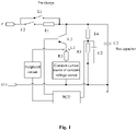
- Fig. 1 is a circuit diagram of the bus short-circuit detection circuit according to embodiments of the present disclosure. As shown in Fig. 1 , the bus short-circuit detection circuit includes a strong voltage detection circuit, a weak electricity charge circuit, a weak charge current detection circuit and a pre-charge circuit.
- the strong voltage detection circuit is configured to detect whether a bus voltage of a unit is abnormal before the bus voltage is charged.
- the weak electricity charge circuit is connected with the strong voltage detection circuit, and is configured to charge a bus when the strong voltage detection circuit detects that the bus voltage of the unit is abnormal.
- the weak charge current detection circuit is connected with the weak electricity charge circuit, and is configured to detect a charge current variation of the weak electricity charge circuit.
- the pre-charge circuit is respectively connected with the strong voltage detection circuit and the weak electricity charge circuit, and is configured to start in a case that the charge current variation of the weak electricity charge circuit indicates that the bus is not in a short-circuited state.
- the bus is charged through the weak electricity charge circuit in the case that abnormal bus voltage is detected, and whether the bus is in the short-circuited state is determined according to the charge current variation; if it is determined that the bus is not in the short-circuited state, the pre-charge circuit can be started normally, so that a rear-end circuit is protected from secondary damage and current shock in case of high voltage strong electricity short-circuit; in such a manner, the technical problem which is that a related detection circuit detects bus short-circuit to cause that the rear-end circuit is not safe is solved, at the same time, a design margin of the pre-charge circuit is reduced.
- the weak electricity charge circuit includes: a switch K3; a current-limiting resistor R3, which is connected with the switch K3 and is configured to control charging time period of the weak electricity charge circuit; and a charge power supply.
- the charge power supply is a voltage source or a constant current source.
- the current-limiting resistor R3 can also function in limiting current.
- the weak charge current detection circuit includes: a current sensor L1, which is connected between the switch K3 and the current-limiting resistor R3; and a peripheral circuit, which is connected with the current sensor L1 in series.
- the strong voltage detection circuit includes: a resistor R4; a resistor R5, which is connected with the resistor R4 in series; a capacitor C2, which is connected with the resistor R5 in parallel.
- a branch consists of the resistor R4 and the resistor R5, one end of the branch is connected with one end of a bus capacitor, the other end of the branch is connected with the other end of the bus capacitor, and the branch is configured to detect a voltage of the bus capacitor.
- the pre-charge circuit includes: a switch K1; a switch K2; and a resistor R1, which is connected the switch K2 in series.
- a branch consists of the switch K2 and the resistor R1, one end of the branch is connected with one end of the switch K1 and the other end of the branch is connected with the other end of the switch K1.
- the switch K1, the switch K2 and the resistor R1 form the pre-charge circuit.
- the capacitor C2 functions in filtering; if the value of the current bus capacitor C3 is greater than a certain set value, the bus is normal, and the pre-charge circuit works normally; if the value of the current bus capacitor C3 is less than the certain set value, the weak electricity charge circuit is started, and the weak electricity charge circuit consists of the switch K3, the resistor R3 and the voltage source or the constant current source.
- the switch K3 can be either a power tube or a relay, and plays a role of switch.
- the resistor R3 functions in limiting the current and controlling weak electricity charge time.
- the voltage source or the constant current source is the charge power supply (the circuit of the part can also form the weak electricity charge circuit by other circuits). After a certain period of time, the charge current variation at this point is detected through the weak charge current detection circuit, and the weak charge current detection circuit consists of the current sensor L1 and the peripheral circuit (which can also be the weak charge current detection circuit consisting of other circuits).
- the circuit prevents a strong impulse current from causing secondary damage to the back-end circuit, and avoids an increased margin in designing the pre-charge circuit due to considering the short circuit problem of the bus, so the cost is saved, and the volume of the pre-charge circuit is reduced.
- a constant voltage source or a constant current source can be applied to supplying power for other circuits after pre-charge detection is completed.
- the circuit shown in Fig. 1 is only used for illustrating the principles of detecting bus short-circuit and opening circuit in the embodiment; the embodiment is not limited to the circuit shown in Fig. 1 , and the specific circuit can be adjusted according to the actual application.
- Fig. 2 shows a flowchart of the bus short-circuit detection method according to some embodiments of the present disclosure. As shown in Fig. 2 , the method include the following steps.
- the weak electricity charge circuit is started in a case that the strong voltage detection circuit detects that the bus voltage of the unit is abnormal before the bus voltage is charged, the weak electricity charge circuit is configured to charge the bus.
- the bus voltage detected by the strong voltage detection circuit When the bus voltage is detected before the bus voltage is charged, it can be determined whether the bus voltage detected by the strong voltage detection circuit is greater than a preset value; if the bus voltage detected by the strong voltage detection circuit is greater than the preset value, it is determined that the bus voltage is normal; if the bus voltage detected by the strong voltage detection circuit is less than the preset value, it is determined that the bus voltage is abnormal.
- the bus voltage In the case that the bus voltage is greater than the preset value, it is determined that the bus voltage is normal and can supply power for the unit. In the case that the bus voltage is less than the preset value, the bus voltage is abnormal and may be short-circuited. In this case, the weak electricity charge circuit is started to charge the bus capacitor. Charging through the weak electricity charge circuit prevents the circuit from being damaged by the strong voltage.
- the charge current variation of the weak electricity charge circuit is detected.
- the charge current variation of the weak electricity charge circuit with a period of time is detected. If the charge current variation does not change over time, and it is the constant current, it is determined that the bus is in the short-circuited state. If the charge current variation gradually decreases over time, it is determined that the bus is normal. That is, it is detected that the charge current variation of the weak electricity charge circuit to indicate whether the charging current is constant or decreases gradually; when the charge current variation indicates that the current of the weak electricity charge circuit is constant, it is determined that the bus is in the short-circuited state; and when the charge current variation indicates that the current of the weak electricity charge circuit decreases gradually, it is determined that the bus is not in a short-circuited state.
- the pre-charge circuit is started in the case that the charge current variation indicates that the bus is not in the short-circuited state.
- Whether the bus is in the short-circuited state can be determined according to the charge current variation. If the bus is in the short-circuited state, it is necessary to stop the unit for detection; if the bus is not in the short-circuited state, the pre-charge circuit can be started.
- the bus is charged through the weak electricity charge circuit in the case that abnormal bus voltage is detected, and whether the bus is in the short-circuited state is determined according to the charge current variation; if it is determined that the bus is not in the short-circuited state, the pre-charge circuit can be started normally, so that a rear-end circuit is protected from secondary damage and current shock in case of high voltage strong electricity short-circuit; in such a manner, the technical problem which is that a related detection circuit detects bus short-circuit to cause that the rear-end circuit is not safe is solved, at the same time, a design margin of the pre-charge circuit is reduced.
- the weak electricity charge circuit is broken, and the pre-charge circuit is started.
- the weak electricity charge circuit is not constant current, it is determined that the bus is in the short-circuited state, and in this case, the weak electricity charge circuit is no longer needed to charge, and then, the weak electricity charge circuit is broken, at the same time, the pre-charge circuit is started to start the unit.
- the unit is shut down. Then it is detected that the unit has fault, and the fault is removed, the bus short-circuit detection method is performed again.
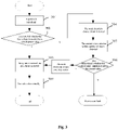
- the bus short-circuit detection method of the embodiment is described below referring to Fig. 3 .
- the embodiments of the present disclosure also provide a storage medium.
- the storage medium includes a stored program.
- the program executes the bus short-circuit detection method.
- the embodiments of the present disclosure also provide a processor.
- the processor is used for running a program.
- the program executes, when running, the bus short-circuit detection method.
- the units described as separate parts may be or may not be separate physically.
- the part shown as the unit may be or may not be a physical unit, that is to say, it may be in a place or distributed on multiple network units. Part or all of the units may be selected to achieve the purpose of the solutions of the embodiments according to a practical requirement.
- all the function units in the embodiments of the disclosure may be integrated in a processing unit; or the units exist separately and physically; or two or more than two units are integrated in a unit.
- the integrated unit may be realized in form of hardware or in form of software function unit.
- the integrated unit is implemented by software function modules, and the software function modules are sold or used as independent products, they can also be stored in a computer readable storage medium.
- the technical solution of the embodiments of the present disclosure substantially or the part making a contribution to the conventional art can be embodied in the form of software product; the computer software product is stored in a storage medium, and includes a number of instructions to make a computer device (which may be a personal computer, a server or a network device, etc.) perform all or part of steps of the method in each embodiment of the present disclosure.
- the storage media include, but not limited to, a USB flash disk, a Read-Only Memory (ROM), a Random Access Memory (RAM), a mobile hard disk, a magnetic disk, a compact disc, and other media capable of storing the program codes.
- the bus is charged through the weak electricity charge circuit in the case that abnormal bus voltage is detected before the bus voltage is charged, and whether the bus is in a short-circuited state is determined according to the charge current variation; if it is determined that the bus is not in the short-circuited state, the pre-charge circuit can be started normally, so that a rear-end circuit is protected from secondary damage and current shock in case of high voltage strong electricity short-circuit; in such a manner, the technical problem which is that a related detection circuit detects bus short-circuit to cause that the rear-end circuit is not safe is solved, at the same time, a design margin of the pre-charge circuit is reduced.
Landscapes
- Physics & Mathematics (AREA)
- General Physics & Mathematics (AREA)
- Engineering & Computer Science (AREA)
- Power Engineering (AREA)
- Testing Of Short-Circuits, Discontinuities, Leakage, Or Incorrect Line Connections (AREA)
- Emergency Protection Circuit Devices (AREA)
- Protection Of Static Devices (AREA)
- Charge And Discharge Circuits For Batteries Or The Like (AREA)
Claims (12)
- Buskurzschlussdetektionsverfahren, das Folgendes umfasst:Starten einer Schwachstromladeschaltung in einem Fall, dass eine Hochstrom-Spannungsdetektionsschaltung detektiert hat, dass eine Busspannung einer Einheit anormal ist, bevor die Busspannung geladen wird, wobei die Schwachstromladeschaltung dazu konfiguriert ist, den Bus zu laden;Detektieren einer Ladestromvariation der Schwachstromladeschaltung; undStarten einer Vorladeschaltung in einem Fall, dass die Ladestromvariation angibt, dass sich der Bus nicht in einem kurzgeschlossenen Zustand befindet.
- Verfahren nach Anspruch 1, wobei das Detektieren der Ladestromvariation der Schwachstromladeschaltung umfasst:Detektieren, ob eine Ladestromvariation eines Ladestroms der Schwachstromladeschaltung angibt, dass der Ladestrom konstant ist oder allmählich abnimmt;wenn die Ladestromvariation angibt, dass der Ladestrom der Schwachstromladeschaltung konstant ist, Bestimmen, dass sich der Bus in dem kurzgeschlossenen Zustand befindet; und wenn die Ladestromvariation angibt, dass der Ladestrom der Schwachstromladeschaltung allmählich abnimmt, Bestimmen, dass sich der Bus nicht in dem kurzgeschlossenen Zustand befindet.
- Verfahren nach Anspruch 1, wobei das Verfahren vor dem Starten der Schwachstromladeschaltung ferner Folgendes umfasst:Bestimmen, ob die Busspannung, die von der Hochspannunugsdetektionsschaltung detektiert wird, größer als ein voreingestellter Wert ist;wenn die Busspannung, die von der Hochspannungsdetektionsschaltung detektiert wird, größer als der voreingestellte Wert ist, Bestimmen, dass die Busspannung normal ist;wenn die Busspannung, die von der Hochspannungsdetektionsschaltung detektiert wird, niedriger als der voreingestellte Wert ist, Bestimmen, dass die Busspannung anormal ist.
- Verfahren nach Anspruch 3, wobei das Verfahren nach dem Bestimmen, dass die Busspannung normal ist, ferner Folgendes umfasst:
Unterbrechen der Schwachstromladeschaltung und Starten der Vorladeschaltung. - Verfahren nach Anspruch 1, wobei das Verfahren nach dem Detektieren der Ladestromvariation der Schwachstromladeschaltung ferner Folgendes umfasst:
Abschalten der Einheit in einem Fall, dass die Ladestromvariation angibt, dass sich der Bus in einem kurzgeschlossenen Zustand befindet. - Buskurzschlussdetektionsschaltung, die Folgendes umfasst:eine Hochspannungsdetektionsschaltung, die dazu konfiguriert ist zu detektieren, ob eine Busspannung einer Einheit anormal ist, bevor die Busspannung geladen wird;eine Schwachstromladeschaltung, die mit der Hochspannungsdetektionsschaltung verbunden ist und dazu konfiguriert ist, den Bus aufzuladen, wenn die Hochspannungsdetektionsschaltung detektiert hat, dass die Busspannung der Einheit anormal ist;eine Schwachstromladestrom-Detektionsschaltung, die mit der Schwachstromladeschaltung verbunden ist und dazu konfiguriert ist, eine Ladestromvariation der Schwachstromladeschaltung zu detektieren; undeine Vorladeschaltung, die jeweils mit der Hochspannungsdetektionsschaltung und der Schwachstromladeschaltung verbunden ist und dazu konfiguriert ist, in einem Fall zu starten, dass die Ladestromvariation der Schwachstromladeschaltung angibt, dass sich der Bus nicht in einem kurzgeschlossenen Zustand befindet.
- Schaltung nach Anspruch 6, wobei die Schwachstromladeschaltung Folgendes umfasst:einen Schalter (K3);einen Strombegrenzungswiderstand (R3), der mit dem Schalter (K3) verbunden und dazu konfiguriert ist, die Ladezeitspanne der Schwachstromladeschaltung zu steuern; undeine Ladestromversorgung, wobei die Ladestromversorgung eine Spannungsquelle oder eine Konstantstromquelle ist.
- Schaltung nach Anspruch 7, wobei die Schwachstromladestrom-Detektionsschaltung Folgendes umfasst:einen Stromsensor (L1), der zwischen dem Schalter (K3) und dem Strombegrenzungswiderstand (R3) angeschlossen ist; undeine Peripherieschaltung, die mit dem Stromsensor (L1) in Reihe geschaltet ist.
- Schaltung nach Anspruch 6, wobei die Hochspannungsdetektionsschaltung Folgendes umfasst:einen ersten Widerstand (R4);einen zweiten Widerstand (R5), der mit dem ersten Widerstand (R4) in Reihe geschaltet ist;einen Kondensator (C2), der mit dem zweiten Widerstand (R5) parallel geschaltet ist;wobei eine Verzweigung aus dem ersten Widerstand (R4) und dem zweiten Widerstand (R5) besteht, ein Ende der Verzweigung mit einem Ende eines Buskondensators verbunden ist, das andere Ende der Verzweigung mit dem anderen Ende des Buskondensators verbunden ist, und die Verzweigung dazu konfiguriert ist, eine Spannung des Buskondensators zu detektieren.
- Schaltung nach Anspruch 6, wobei die Vorladeschaltung Folgendes umfasst:einen ersten Schalter (K1);einen zweiten Schalter (K2); undeinen dritten Widerstand (R1), der mit dem zweiten Schalter (K2) in Reihe geschaltet ist;wobei eine Verzweigung aus dem zweiten Schalter (K2) und dem dritten Widerstand (R1) besteht, ein Ende der Verzweigung mit einem Ende des ersten Schalters (K1) verbunden ist und das andere Ende der Verzweigung mit dem anderen Ende des ersten Schalters (K1) verbunden ist.
- Speichermedium, das ein gespeichertes Programm umfasst; wobei das Programm, wenn es auf einem Prozessor läuft, ein Buskurzschlussdetektionsverfahren nach einem der Ansprüche 1 bis 5 ausführt.
- Prozessor, der zum Ausführen eines Programms verwendet wird; wobei das Programm beim Ausführen ein Buskurzschlussdetektionsverfahren nach einem der Ansprüche 1 bis 5 ausführt.
Applications Claiming Priority (2)
| Application Number | Priority Date | Filing Date | Title |
|---|---|---|---|
| CN201711181466.6A CN108267665B (zh) | 2017-11-22 | 2017-11-22 | 母线短路的检测方法、电路、存储介质和处理器 |
| PCT/CN2018/100219 WO2019100767A1 (zh) | 2017-11-22 | 2018-08-13 | 母线短路的检测方法、电路、存储介质和处理器 |
Publications (3)
| Publication Number | Publication Date |
|---|---|
| EP3715877A1 EP3715877A1 (de) | 2020-09-30 |
| EP3715877A4 EP3715877A4 (de) | 2021-08-11 |
| EP3715877B1 true EP3715877B1 (de) | 2022-09-28 |
Family
ID=62770889
Family Applications (1)
| Application Number | Title | Priority Date | Filing Date |
|---|---|---|---|
| EP18880907.3A Active EP3715877B1 (de) | 2017-11-22 | 2018-08-13 | Buskurzschlussdetektionsverfahren, schaltung, speichermedium und prozessor |
Country Status (4)
| Country | Link |
|---|---|
| US (1) | US11169219B2 (de) |
| EP (1) | EP3715877B1 (de) |
| CN (1) | CN108267665B (de) |
| WO (1) | WO2019100767A1 (de) |
Families Citing this family (8)
| Publication number | Priority date | Publication date | Assignee | Title |
|---|---|---|---|---|
| CN108267665B (zh) * | 2017-11-22 | 2020-10-02 | 珠海格力电器股份有限公司 | 母线短路的检测方法、电路、存储介质和处理器 |
| CN111308274B (zh) * | 2020-03-17 | 2025-03-25 | 贵州民族大学 | 一种线路短路及短路位置检测装置 |
| CN112198451B (zh) * | 2020-09-11 | 2021-10-15 | 珠海格力电器股份有限公司 | 功率电路故障检测系统及故障检测方法 |
| CN113466738B (zh) * | 2021-05-31 | 2024-07-16 | 广东朝阳电子科技股份有限公司 | 短路检测电路 |
| CN113422352B (zh) * | 2021-06-07 | 2022-06-21 | 山东建筑大学 | 一种自动检测短路故障的强电开关电路 |
| CN113363932B (zh) * | 2021-06-07 | 2022-06-21 | 山东建筑大学 | 基于电解电容的串联式短路故障检测和保护电路 |
| CN113820619A (zh) * | 2021-07-21 | 2021-12-21 | 深圳拓邦股份有限公司 | 一种短路检测电路、电子装置及短路检测方法 |
| CN114280377B (zh) * | 2021-12-10 | 2024-02-27 | 珠海格力电器股份有限公司 | 一种用于空调预充电回路检测电路的检测方法及空调 |
Family Cites Families (23)
| Publication number | Priority date | Publication date | Assignee | Title |
|---|---|---|---|---|
| CN1306330A (zh) * | 2000-01-17 | 2001-08-01 | 李元龙 | 以虚拟电流作为保护判据重要元素的微机母线保护 |
| JP3714878B2 (ja) * | 2001-02-19 | 2005-11-09 | 財団法人東北電気保安協会 | 短絡検知器 |
| CN2935619Y (zh) * | 2006-04-25 | 2007-08-15 | 深圳市中传电气技术有限公司 | 一种智能型中、高压大功率变频器预充电电路保护装置 |
| CN101329381A (zh) * | 2008-07-28 | 2008-12-24 | 庞元俊 | 利用电流变化率检测短路故障的方法 |
| US7929323B2 (en) * | 2008-09-26 | 2011-04-19 | Rockwell Automation Technologies, Inc. | Method and apparatus for pre-charging power converters and diagnosing pre-charge faults |
| CN201629677U (zh) * | 2010-04-03 | 2010-11-10 | 东方电子股份有限公司 | 利用低压技术进行高压变频器预充电电路 |
| CN102156243B (zh) * | 2011-03-16 | 2016-08-10 | 艾默生网络能源有限公司 | 一种功率单元熔断器状态的检测方法和装置 |
| KR101322519B1 (ko) * | 2011-10-28 | 2013-10-28 | 현대오트론 주식회사 | 전기 자동차의 누전 검출 장치 및 이를 이용한 누전 검출 방법 |
| US9042146B2 (en) * | 2011-11-14 | 2015-05-26 | Rockwell Automation Technologies, Inc. | DC pre-charge circuit |
| CN103580458A (zh) * | 2012-07-26 | 2014-02-12 | 珠海格力电器股份有限公司 | 电容充电电路的控制方法与控制装置和电容充电电路 |
| CN103036206A (zh) * | 2012-11-29 | 2013-04-10 | 潍柴动力股份有限公司 | 一种电机控制器预充线路故障的检测方法及装置 |
| US9726725B2 (en) * | 2013-08-02 | 2017-08-08 | Jtekt Corporation | Power circuit abnormality detection method |
| CN103457451B (zh) * | 2013-08-22 | 2016-12-28 | 深圳市英威腾电气股份有限公司 | 一种高压变频器低压上电控制电路及其控制方法 |
| CN103647458B (zh) * | 2013-12-24 | 2016-03-23 | 苏州汇川技术有限公司 | 变频系统及给其内的高压变频器进行预充电的方法和装置 |
| CN104038032B (zh) * | 2014-05-26 | 2018-01-05 | 株洲变流技术国家工程研究中心有限公司 | 用于高压变频系统的低压预充电系统及其控制方法 |
| JP6210942B2 (ja) * | 2014-07-07 | 2017-10-11 | 東芝三菱電機産業システム株式会社 | 電動機駆動システム及び電動機駆動システムの直流短絡検出装置 |
| CN104333122B (zh) * | 2014-11-18 | 2018-05-11 | 华为技术有限公司 | 供电总线电路 |
| CN105044529B (zh) * | 2015-08-13 | 2018-04-20 | 国家电网公司 | 变电站直流电源系统故障特征检测方法 |
| JP2017163779A (ja) * | 2016-03-11 | 2017-09-14 | ローム株式会社 | 給電装置、1次側コントローラ、acアダプタ、電子機器、短絡検出方法 |
| US9673695B1 (en) * | 2016-05-24 | 2017-06-06 | Eaton Corporation | System and method for intelligent circuit breaking in adjustable speed drives |
| CN106655750A (zh) * | 2016-12-31 | 2017-05-10 | 徐州中矿大传动与自动化有限公司 | 用于电压源变流器自带线路故障检测功能的预充装置 |
| CN108008235B (zh) * | 2017-11-17 | 2021-02-26 | 珠海格力电器股份有限公司 | 直流母线短路检测方法、装置及检测电路 |
| CN108267665B (zh) * | 2017-11-22 | 2020-10-02 | 珠海格力电器股份有限公司 | 母线短路的检测方法、电路、存储介质和处理器 |
-
2017
- 2017-11-22 CN CN201711181466.6A patent/CN108267665B/zh active Active
-
2018
- 2018-08-13 WO PCT/CN2018/100219 patent/WO2019100767A1/zh not_active Ceased
- 2018-08-13 EP EP18880907.3A patent/EP3715877B1/de active Active
- 2018-08-13 US US16/643,944 patent/US11169219B2/en active Active
Also Published As
| Publication number | Publication date |
|---|---|
| US11169219B2 (en) | 2021-11-09 |
| US20200408851A1 (en) | 2020-12-31 |
| CN108267665B (zh) | 2020-10-02 |
| EP3715877A4 (de) | 2021-08-11 |
| CN108267665A (zh) | 2018-07-10 |
| EP3715877A1 (de) | 2020-09-30 |
| WO2019100767A1 (zh) | 2019-05-31 |
Similar Documents
| Publication | Publication Date | Title |
|---|---|---|
| US11169219B2 (en) | Bus short-circuit detection method and circuit, storage medium and processor | |
| KR102538368B1 (ko) | 전기자동차 충전케이블 제어장치의 자동 재폐로 장치 및 방법 | |
| EP3573176B1 (de) | Heizaggregat für batteriepack und verfahren zur heizungsregelung eines batteriepacks | |
| EP3573174B1 (de) | Heizaggregat für batteriepack und verfahren zur heizungsregelung eines batteriepacks | |
| EP3211750B1 (de) | Verfahren und system zur dynamischen anpassung von batterieunterspannungsschutz | |
| EP3101753B1 (de) | Überspannungs- und überstromschutzschaltung und mobiles endgerät | |
| CN106505660B (zh) | 一种充电保护方法、充电保护器及终端 | |
| CN111525656B (zh) | 电池电能回馈系统以及车辆 | |
| KR20170084306A (ko) | 충전 보호 방법 및 장치 | |
| EP3101762A1 (de) | Netzadapter, endgerät und verfahren zur verarbeitung von impedanzanomalien in ladestromkreis | |
| CN112865070A (zh) | 一种电源系统的控制装置、方法和空调机组 | |
| CN110690752B (zh) | 一种多电池组并联控制的bms管理方法 | |
| KR101976873B1 (ko) | 릴레이 융착 검출장치 및 검출방법 | |
| WO2019192183A1 (zh) | 确定电池状态的方法和装置、芯片、电池及飞行器 | |
| CN210062685U (zh) | 高压放电装置和车辆 | |
| CN109624786B (zh) | 动力电池预充电阻保护控制方法 | |
| KR20180092508A (ko) | 배터리 팩과 외부 시스템의 체결 시 돌입전류와 쇼트전류를 구분하는 스위치 제어장치 및 방법 | |
| WO2017152586A1 (zh) | 电池保护方法及装置、终端 | |
| CN117885539A (zh) | 一种动力电池的切断方法、控制系统及车辆 | |
| JP2015173568A (ja) | 電池保護回路および電池パック | |
| WO2019184386A1 (zh) | 无人飞行器电池安全保护方法及其装置 | |
| CN106797132B (zh) | 电池充电方法、充电系统、充电器及电池 | |
| CN210837189U (zh) | 一种电子盘的多功能物理自毁和掉电保护电路 | |
| CN107834661A (zh) | 一种多串锂电池保护控制系统及控制电路 | |
| CN110138056A (zh) | 应急电源保护方法和装置 |
Legal Events
| Date | Code | Title | Description |
|---|---|---|---|
| STAA | Information on the status of an ep patent application or granted ep patent |
Free format text: STATUS: THE INTERNATIONAL PUBLICATION HAS BEEN MADE |
|
| PUAI | Public reference made under article 153(3) epc to a published international application that has entered the european phase |
Free format text: ORIGINAL CODE: 0009012 |
|
| STAA | Information on the status of an ep patent application or granted ep patent |
Free format text: STATUS: REQUEST FOR EXAMINATION WAS MADE |
|
| 17P | Request for examination filed |
Effective date: 20200302 |
|
| AK | Designated contracting states |
Kind code of ref document: A1 Designated state(s): AL AT BE BG CH CY CZ DE DK EE ES FI FR GB GR HR HU IE IS IT LI LT LU LV MC MK MT NL NO PL PT RO RS SE SI SK SM TR |
|
| AX | Request for extension of the european patent |
Extension state: BA ME |
|
| DAV | Request for validation of the european patent (deleted) | ||
| DAX | Request for extension of the european patent (deleted) | ||
| REG | Reference to a national code |
Ref country code: DE Ref legal event code: R079 Ref document number: 602018041265 Country of ref document: DE Free format text: PREVIOUS MAIN CLASS: G01R0031020000 Ipc: G01R0031520000 |
|
| A4 | Supplementary search report drawn up and despatched |
Effective date: 20210708 |
|
| RIC1 | Information provided on ipc code assigned before grant |
Ipc: G01R 31/52 20200101AFI20210702BHEP Ipc: H02H 9/02 20060101ALI20210702BHEP |
|
| GRAP | Despatch of communication of intention to grant a patent |
Free format text: ORIGINAL CODE: EPIDOSNIGR1 |
|
| STAA | Information on the status of an ep patent application or granted ep patent |
Free format text: STATUS: GRANT OF PATENT IS INTENDED |
|
| INTG | Intention to grant announced |
Effective date: 20220603 |
|
| GRAS | Grant fee paid |
Free format text: ORIGINAL CODE: EPIDOSNIGR3 |
|
| RAP3 | Party data changed (applicant data changed or rights of an application transferred) |
Owner name: GREE ELECTRIC APPLIANCES, INC. OF ZHUHAI Owner name: GREE ELECTRIC APPLIANCES (WUHAN) CO., LTD. |
|
| GRAA | (expected) grant |
Free format text: ORIGINAL CODE: 0009210 |
|
| STAA | Information on the status of an ep patent application or granted ep patent |
Free format text: STATUS: THE PATENT HAS BEEN GRANTED |
|
| AK | Designated contracting states |
Kind code of ref document: B1 Designated state(s): AL AT BE BG CH CY CZ DE DK EE ES FI FR GB GR HR HU IE IS IT LI LT LU LV MC MK MT NL NO PL PT RO RS SE SI SK SM TR |
|
| REG | Reference to a national code |
Ref country code: GB Ref legal event code: FG4D |
|
| REG | Reference to a national code |
Ref country code: CH Ref legal event code: EP |
|
| REG | Reference to a national code |
Ref country code: DE Ref legal event code: R096 Ref document number: 602018041265 Country of ref document: DE |
|
| REG | Reference to a national code |
Ref country code: AT Ref legal event code: REF Ref document number: 1521576 Country of ref document: AT Kind code of ref document: T Effective date: 20221015 |
|
| REG | Reference to a national code |
Ref country code: IE Ref legal event code: FG4D |
|
| REG | Reference to a national code |
Ref country code: LT Ref legal event code: MG9D |
|
| PG25 | Lapsed in a contracting state [announced via postgrant information from national office to epo] |
Ref country code: SE Free format text: LAPSE BECAUSE OF FAILURE TO SUBMIT A TRANSLATION OF THE DESCRIPTION OR TO PAY THE FEE WITHIN THE PRESCRIBED TIME-LIMIT Effective date: 20220928 Ref country code: RS Free format text: LAPSE BECAUSE OF FAILURE TO SUBMIT A TRANSLATION OF THE DESCRIPTION OR TO PAY THE FEE WITHIN THE PRESCRIBED TIME-LIMIT Effective date: 20220928 Ref country code: NO Free format text: LAPSE BECAUSE OF FAILURE TO SUBMIT A TRANSLATION OF THE DESCRIPTION OR TO PAY THE FEE WITHIN THE PRESCRIBED TIME-LIMIT Effective date: 20221228 Ref country code: LV Free format text: LAPSE BECAUSE OF FAILURE TO SUBMIT A TRANSLATION OF THE DESCRIPTION OR TO PAY THE FEE WITHIN THE PRESCRIBED TIME-LIMIT Effective date: 20220928 Ref country code: LT Free format text: LAPSE BECAUSE OF FAILURE TO SUBMIT A TRANSLATION OF THE DESCRIPTION OR TO PAY THE FEE WITHIN THE PRESCRIBED TIME-LIMIT Effective date: 20220928 Ref country code: FI Free format text: LAPSE BECAUSE OF FAILURE TO SUBMIT A TRANSLATION OF THE DESCRIPTION OR TO PAY THE FEE WITHIN THE PRESCRIBED TIME-LIMIT Effective date: 20220928 |
|
| REG | Reference to a national code |
Ref country code: NL Ref legal event code: MP Effective date: 20220928 |
|
| REG | Reference to a national code |
Ref country code: AT Ref legal event code: MK05 Ref document number: 1521576 Country of ref document: AT Kind code of ref document: T Effective date: 20220928 |
|
| PG25 | Lapsed in a contracting state [announced via postgrant information from national office to epo] |
Ref country code: HR Free format text: LAPSE BECAUSE OF FAILURE TO SUBMIT A TRANSLATION OF THE DESCRIPTION OR TO PAY THE FEE WITHIN THE PRESCRIBED TIME-LIMIT Effective date: 20220928 Ref country code: GR Free format text: LAPSE BECAUSE OF FAILURE TO SUBMIT A TRANSLATION OF THE DESCRIPTION OR TO PAY THE FEE WITHIN THE PRESCRIBED TIME-LIMIT Effective date: 20221229 |
|
| PG25 | Lapsed in a contracting state [announced via postgrant information from national office to epo] |
Ref country code: SM Free format text: LAPSE BECAUSE OF FAILURE TO SUBMIT A TRANSLATION OF THE DESCRIPTION OR TO PAY THE FEE WITHIN THE PRESCRIBED TIME-LIMIT Effective date: 20220928 Ref country code: RO Free format text: LAPSE BECAUSE OF FAILURE TO SUBMIT A TRANSLATION OF THE DESCRIPTION OR TO PAY THE FEE WITHIN THE PRESCRIBED TIME-LIMIT Effective date: 20220928 Ref country code: PT Free format text: LAPSE BECAUSE OF FAILURE TO SUBMIT A TRANSLATION OF THE DESCRIPTION OR TO PAY THE FEE WITHIN THE PRESCRIBED TIME-LIMIT Effective date: 20230130 Ref country code: ES Free format text: LAPSE BECAUSE OF FAILURE TO SUBMIT A TRANSLATION OF THE DESCRIPTION OR TO PAY THE FEE WITHIN THE PRESCRIBED TIME-LIMIT Effective date: 20220928 Ref country code: CZ Free format text: LAPSE BECAUSE OF FAILURE TO SUBMIT A TRANSLATION OF THE DESCRIPTION OR TO PAY THE FEE WITHIN THE PRESCRIBED TIME-LIMIT Effective date: 20220928 Ref country code: AT Free format text: LAPSE BECAUSE OF FAILURE TO SUBMIT A TRANSLATION OF THE DESCRIPTION OR TO PAY THE FEE WITHIN THE PRESCRIBED TIME-LIMIT Effective date: 20220928 |
|
| PG25 | Lapsed in a contracting state [announced via postgrant information from national office to epo] |
Ref country code: SK Free format text: LAPSE BECAUSE OF FAILURE TO SUBMIT A TRANSLATION OF THE DESCRIPTION OR TO PAY THE FEE WITHIN THE PRESCRIBED TIME-LIMIT Effective date: 20220928 Ref country code: PL Free format text: LAPSE BECAUSE OF FAILURE TO SUBMIT A TRANSLATION OF THE DESCRIPTION OR TO PAY THE FEE WITHIN THE PRESCRIBED TIME-LIMIT Effective date: 20220928 Ref country code: IS Free format text: LAPSE BECAUSE OF FAILURE TO SUBMIT A TRANSLATION OF THE DESCRIPTION OR TO PAY THE FEE WITHIN THE PRESCRIBED TIME-LIMIT Effective date: 20230128 Ref country code: EE Free format text: LAPSE BECAUSE OF FAILURE TO SUBMIT A TRANSLATION OF THE DESCRIPTION OR TO PAY THE FEE WITHIN THE PRESCRIBED TIME-LIMIT Effective date: 20220928 |
|
| REG | Reference to a national code |
Ref country code: DE Ref legal event code: R097 Ref document number: 602018041265 Country of ref document: DE |
|
| PG25 | Lapsed in a contracting state [announced via postgrant information from national office to epo] |
Ref country code: NL Free format text: LAPSE BECAUSE OF FAILURE TO SUBMIT A TRANSLATION OF THE DESCRIPTION OR TO PAY THE FEE WITHIN THE PRESCRIBED TIME-LIMIT Effective date: 20220928 Ref country code: AL Free format text: LAPSE BECAUSE OF FAILURE TO SUBMIT A TRANSLATION OF THE DESCRIPTION OR TO PAY THE FEE WITHIN THE PRESCRIBED TIME-LIMIT Effective date: 20220928 |
|
| P01 | Opt-out of the competence of the unified patent court (upc) registered |
Effective date: 20230530 |
|
| PG25 | Lapsed in a contracting state [announced via postgrant information from national office to epo] |
Ref country code: DK Free format text: LAPSE BECAUSE OF FAILURE TO SUBMIT A TRANSLATION OF THE DESCRIPTION OR TO PAY THE FEE WITHIN THE PRESCRIBED TIME-LIMIT Effective date: 20220928 |
|
| PLBE | No opposition filed within time limit |
Free format text: ORIGINAL CODE: 0009261 |
|
| STAA | Information on the status of an ep patent application or granted ep patent |
Free format text: STATUS: NO OPPOSITION FILED WITHIN TIME LIMIT |
|
| 26N | No opposition filed |
Effective date: 20230629 |
|
| PG25 | Lapsed in a contracting state [announced via postgrant information from national office to epo] |
Ref country code: SI Free format text: LAPSE BECAUSE OF FAILURE TO SUBMIT A TRANSLATION OF THE DESCRIPTION OR TO PAY THE FEE WITHIN THE PRESCRIBED TIME-LIMIT Effective date: 20220928 |
|
| PG25 | Lapsed in a contracting state [announced via postgrant information from national office to epo] |
Ref country code: MC Free format text: LAPSE BECAUSE OF FAILURE TO SUBMIT A TRANSLATION OF THE DESCRIPTION OR TO PAY THE FEE WITHIN THE PRESCRIBED TIME-LIMIT Effective date: 20220928 |
|
| REG | Reference to a national code |
Ref country code: CH Ref legal event code: PL |
|
| PG25 | Lapsed in a contracting state [announced via postgrant information from national office to epo] |
Ref country code: MC Free format text: LAPSE BECAUSE OF FAILURE TO SUBMIT A TRANSLATION OF THE DESCRIPTION OR TO PAY THE FEE WITHIN THE PRESCRIBED TIME-LIMIT Effective date: 20220928 |
|
| PG25 | Lapsed in a contracting state [announced via postgrant information from national office to epo] |
Ref country code: LU Free format text: LAPSE BECAUSE OF NON-PAYMENT OF DUE FEES Effective date: 20230813 |
|
| GBPC | Gb: european patent ceased through non-payment of renewal fee |
Effective date: 20230813 |
|
| PG25 | Lapsed in a contracting state [announced via postgrant information from national office to epo] |
Ref country code: LU Free format text: LAPSE BECAUSE OF NON-PAYMENT OF DUE FEES Effective date: 20230813 Ref country code: CH Free format text: LAPSE BECAUSE OF NON-PAYMENT OF DUE FEES Effective date: 20230831 |
|
| REG | Reference to a national code |
Ref country code: BE Ref legal event code: MM Effective date: 20230831 |
|
| REG | Reference to a national code |
Ref country code: IE Ref legal event code: MM4A |
|
| PG25 | Lapsed in a contracting state [announced via postgrant information from national office to epo] |
Ref country code: IT Free format text: LAPSE BECAUSE OF FAILURE TO SUBMIT A TRANSLATION OF THE DESCRIPTION OR TO PAY THE FEE WITHIN THE PRESCRIBED TIME-LIMIT Effective date: 20220928 |
|
| PG25 | Lapsed in a contracting state [announced via postgrant information from national office to epo] |
Ref country code: IE Free format text: LAPSE BECAUSE OF NON-PAYMENT OF DUE FEES Effective date: 20230813 |
|
| PG25 | Lapsed in a contracting state [announced via postgrant information from national office to epo] |
Ref country code: GB Free format text: LAPSE BECAUSE OF NON-PAYMENT OF DUE FEES Effective date: 20230813 |
|
| PG25 | Lapsed in a contracting state [announced via postgrant information from national office to epo] |
Ref country code: IE Free format text: LAPSE BECAUSE OF NON-PAYMENT OF DUE FEES Effective date: 20230813 Ref country code: GB Free format text: LAPSE BECAUSE OF NON-PAYMENT OF DUE FEES Effective date: 20230813 Ref country code: FR Free format text: LAPSE BECAUSE OF NON-PAYMENT OF DUE FEES Effective date: 20230831 |
|
| PG25 | Lapsed in a contracting state [announced via postgrant information from national office to epo] |
Ref country code: BE Free format text: LAPSE BECAUSE OF NON-PAYMENT OF DUE FEES Effective date: 20230831 |
|
| PG25 | Lapsed in a contracting state [announced via postgrant information from national office to epo] |
Ref country code: BG Free format text: LAPSE BECAUSE OF FAILURE TO SUBMIT A TRANSLATION OF THE DESCRIPTION OR TO PAY THE FEE WITHIN THE PRESCRIBED TIME-LIMIT Effective date: 20220928 |
|
| PG25 | Lapsed in a contracting state [announced via postgrant information from national office to epo] |
Ref country code: BG Free format text: LAPSE BECAUSE OF FAILURE TO SUBMIT A TRANSLATION OF THE DESCRIPTION OR TO PAY THE FEE WITHIN THE PRESCRIBED TIME-LIMIT Effective date: 20220928 |
|
| PG25 | Lapsed in a contracting state [announced via postgrant information from national office to epo] |
Ref country code: CY Free format text: LAPSE BECAUSE OF FAILURE TO SUBMIT A TRANSLATION OF THE DESCRIPTION OR TO PAY THE FEE WITHIN THE PRESCRIBED TIME-LIMIT; INVALID AB INITIO Effective date: 20180813 |
|
| PG25 | Lapsed in a contracting state [announced via postgrant information from national office to epo] |
Ref country code: HU Free format text: LAPSE BECAUSE OF FAILURE TO SUBMIT A TRANSLATION OF THE DESCRIPTION OR TO PAY THE FEE WITHIN THE PRESCRIBED TIME-LIMIT; INVALID AB INITIO Effective date: 20180813 |
|
| PGFP | Annual fee paid to national office [announced via postgrant information from national office to epo] |
Ref country code: DE Payment date: 20250819 Year of fee payment: 8 |
|
| PG25 | Lapsed in a contracting state [announced via postgrant information from national office to epo] |
Ref country code: TR Free format text: LAPSE BECAUSE OF FAILURE TO SUBMIT A TRANSLATION OF THE DESCRIPTION OR TO PAY THE FEE WITHIN THE PRESCRIBED TIME-LIMIT Effective date: 20220928 |