EP3715776A1 - Cartouche comprenant des cordeaux d`allumage - Google Patents
Cartouche comprenant des cordeaux d`allumage Download PDFInfo
- Publication number
- EP3715776A1 EP3715776A1 EP20158974.4A EP20158974A EP3715776A1 EP 3715776 A1 EP3715776 A1 EP 3715776A1 EP 20158974 A EP20158974 A EP 20158974A EP 3715776 A1 EP3715776 A1 EP 3715776A1
- Authority
- EP
- European Patent Office
- Prior art keywords
- cords
- projectile
- cartridge
- strand
- integral
- Prior art date
- Legal status (The legal status is an assumption and is not a legal conclusion. Google has not performed a legal analysis and makes no representation as to the accuracy of the status listed.)
- Granted
Links
- 230000000977 initiatory effect Effects 0.000 claims abstract description 30
- 239000003380 propellant Substances 0.000 claims abstract description 14
- 210000004907 gland Anatomy 0.000 claims abstract description 5
- 239000004033 plastic Substances 0.000 description 6
- 229920003023 plastic Polymers 0.000 description 6
- 239000000843 powder Substances 0.000 description 5
- 239000000853 adhesive Substances 0.000 description 4
- 230000001070 adhesive effect Effects 0.000 description 4
- 239000000463 material Substances 0.000 description 4
- 239000000203 mixture Substances 0.000 description 4
- FGIUAXJPYTZDNR-UHFFFAOYSA-N potassium nitrate Chemical compound [K+].[O-][N+]([O-])=O FGIUAXJPYTZDNR-UHFFFAOYSA-N 0.000 description 4
- ZOXJGFHDIHLPTG-UHFFFAOYSA-N Boron Chemical compound [B] ZOXJGFHDIHLPTG-UHFFFAOYSA-N 0.000 description 2
- 239000004698 Polyethylene Substances 0.000 description 2
- 229910052782 aluminium Inorganic materials 0.000 description 2
- XAGFODPZIPBFFR-UHFFFAOYSA-N aluminium Chemical compound [Al] XAGFODPZIPBFFR-UHFFFAOYSA-N 0.000 description 2
- 229910052796 boron Inorganic materials 0.000 description 2
- AXZAYXJCENRGIM-UHFFFAOYSA-J dipotassium;tetrabromoplatinum(2-) Chemical compound [K+].[K+].[Br-].[Br-].[Br-].[Br-].[Pt+2] AXZAYXJCENRGIM-UHFFFAOYSA-J 0.000 description 2
- 238000012856 packing Methods 0.000 description 2
- -1 polyethylene Polymers 0.000 description 2
- 229920000573 polyethylene Polymers 0.000 description 2
- 235000010333 potassium nitrate Nutrition 0.000 description 2
- 239000004323 potassium nitrate Substances 0.000 description 2
- 229910001487 potassium perchlorate Inorganic materials 0.000 description 2
- 208000031968 Cadaver Diseases 0.000 description 1
- 239000000020 Nitrocellulose Substances 0.000 description 1
- 239000011324 bead Substances 0.000 description 1
- 239000002360 explosive Substances 0.000 description 1
- 238000010304 firing Methods 0.000 description 1
- 239000007789 gas Substances 0.000 description 1
- 238000007373 indentation Methods 0.000 description 1
- 238000004519 manufacturing process Methods 0.000 description 1
- 229910052751 metal Inorganic materials 0.000 description 1
- 239000002184 metal Substances 0.000 description 1
- 229920001220 nitrocellulos Polymers 0.000 description 1
- 230000002093 peripheral effect Effects 0.000 description 1
- 238000010079 rubber tapping Methods 0.000 description 1
- 230000035939 shock Effects 0.000 description 1
Images
Classifications
-
- F—MECHANICAL ENGINEERING; LIGHTING; HEATING; WEAPONS; BLASTING
- F42—AMMUNITION; BLASTING
- F42B—EXPLOSIVE CHARGES, e.g. FOR BLASTING, FIREWORKS, AMMUNITION
- F42B5/00—Cartridge ammunition, e.g. separately-loaded propellant charges
- F42B5/02—Cartridges, i.e. cases with charge and missile
- F42B5/08—Cartridges, i.e. cases with charge and missile modified for electric ignition
-
- C—CHEMISTRY; METALLURGY
- C06—EXPLOSIVES; MATCHES
- C06C—DETONATING OR PRIMING DEVICES; FUSES; CHEMICAL LIGHTERS; PYROPHORIC COMPOSITIONS
- C06C5/00—Fuses, e.g. fuse cords
- C06C5/06—Fuse igniting means; Fuse connectors
-
- F—MECHANICAL ENGINEERING; LIGHTING; HEATING; WEAPONS; BLASTING
- F42—AMMUNITION; BLASTING
- F42C—AMMUNITION FUZES; ARMING OR SAFETY MEANS THEREFOR
- F42C19/00—Details of fuzes
- F42C19/08—Primers; Detonators
- F42C19/0823—Primers or igniters for the initiation or the propellant charge in a cartridged ammunition
- F42C19/083—Primers or igniters for the initiation or the propellant charge in a cartridged ammunition characterised by the shape and configuration of the base element embedded in the cartridge bottom, e.g. the housing for the squib or percussion cap
-
- F—MECHANICAL ENGINEERING; LIGHTING; HEATING; WEAPONS; BLASTING
- F42—AMMUNITION; BLASTING
- F42C—AMMUNITION FUZES; ARMING OR SAFETY MEANS THEREFOR
- F42C19/00—Details of fuzes
- F42C19/08—Primers; Detonators
- F42C19/0823—Primers or igniters for the initiation or the propellant charge in a cartridged ammunition
- F42C19/0834—Arrangements of a multiplicity of primers or detonators dispersed within a propellant charge for increased efficiency
-
- F—MECHANICAL ENGINEERING; LIGHTING; HEATING; WEAPONS; BLASTING
- F42—AMMUNITION; BLASTING
- F42C—AMMUNITION FUZES; ARMING OR SAFETY MEANS THEREFOR
- F42C19/00—Details of fuzes
- F42C19/08—Primers; Detonators
- F42C19/12—Primers; Detonators electric
-
- F—MECHANICAL ENGINEERING; LIGHTING; HEATING; WEAPONS; BLASTING
- F42—AMMUNITION; BLASTING
- F42B—EXPLOSIVE CHARGES, e.g. FOR BLASTING, FIREWORKS, AMMUNITION
- F42B12/00—Projectiles, missiles or mines characterised by the warhead, the intended effect, or the material
- F42B12/02—Projectiles, missiles or mines characterised by the warhead, the intended effect, or the material characterised by the warhead or the intended effect
- F42B12/04—Projectiles, missiles or mines characterised by the warhead, the intended effect, or the material characterised by the warhead or the intended effect of armour-piercing type
- F42B12/06—Projectiles, missiles or mines characterised by the warhead, the intended effect, or the material characterised by the warhead or the intended effect of armour-piercing type with hard or heavy core; Kinetic energy penetrators
-
- F—MECHANICAL ENGINEERING; LIGHTING; HEATING; WEAPONS; BLASTING
- F42—AMMUNITION; BLASTING
- F42B—EXPLOSIVE CHARGES, e.g. FOR BLASTING, FIREWORKS, AMMUNITION
- F42B14/00—Projectiles or missiles characterised by arrangements for guiding or sealing them inside barrels, or for lubricating or cleaning barrels
- F42B14/06—Sub-calibre projectiles having sabots; Sabots therefor
- F42B14/061—Sabots for long rod fin stabilised kinetic energy projectiles, i.e. multisegment sabots attached midway on the projectile
-
- F—MECHANICAL ENGINEERING; LIGHTING; HEATING; WEAPONS; BLASTING
- F42—AMMUNITION; BLASTING
- F42B—EXPLOSIVE CHARGES, e.g. FOR BLASTING, FIREWORKS, AMMUNITION
- F42B5/00—Cartridge ammunition, e.g. separately-loaded propellant charges
- F42B5/02—Cartridges, i.e. cases with charge and missile
- F42B5/045—Cartridges, i.e. cases with charge and missile of telescopic type
-
- F—MECHANICAL ENGINEERING; LIGHTING; HEATING; WEAPONS; BLASTING
- F42—AMMUNITION; BLASTING
- F42B—EXPLOSIVE CHARGES, e.g. FOR BLASTING, FIREWORKS, AMMUNITION
- F42B5/00—Cartridge ammunition, e.g. separately-loaded propellant charges
- F42B5/02—Cartridges, i.e. cases with charge and missile
- F42B5/18—Caseless ammunition; Cartridges having combustible cases
Definitions
- the technical field of the invention is that of cartridges comprising a propellant charge housed in a case and devices for igniting such propellant charges.
- the device for igniting the propellant charge comprises energetic ignition cords which extend between an initiation means secured to a rear part of the case and the projectile.
- the ignition cords most often comprise a plastic tube containing a pyrotechnic composition such as black powder or a composition combining boron and potassium nitrate or else aluminum and potassium perchlorate. These cords are well known and described in particular by the patent FR2441598 .
- the ignition cords make it possible to ensure ignition of the propellant charge in a cartridge whose projectile penetrates deeply inside the powder bed, in particular for an arrow type projectile with a very long bar.
- conventional axial igniter tubes cannot be incorporated with such projectiles.
- the cords extend between an axial igniter tube linked to the base and the case or the projectile.
- the cords are arranged along the internal wall of the case and they are held in place by plastic stars.
- the holding stars risk creating unburnt material and also disturbing the propagation of the ignition flow.
- the cartridge described by the patent EP1092940 comprises ignition cords grouped in a strand which is introduced into an axial igniter base.
- the cartridge according to the invention ensures reliable positioning of the ignition cords, guaranteeing the resistance of the cartridge to vibrations and shocks due in particular to transport.
- This reliable positioning also ensures ignition with reproducible pyrotechnic characteristics and without pressure waves.
- the invention relates to a cartridge comprising a projectile integral with a case containing a propellant charge and closed by a base, a device for igniting the propellant charge comprising at least two energetic ignition cords extending between a initiation means integral with a rear part of the case and the projectile, cartridge in which the cords are joined at the level of their rear part so as to form a strand, cartridge characterized in that the cords are fixed by at least one fastening means integral with the cartridge, the strand being linked to the initiation means by a cable gland allowing all both radially and axially immobilize the cords relative to the initiating means while keeping the cords stretched between their attachment means and the initiation means.
- the stuffing box can include a sheath surrounding the strand and on which is positioned a nut which engages on a thread carried by the initiating means, the nut comprising a conical bearing engaging on the sheath during the Tightening.
- the initiation means may include an internal chamber in which is positioned at least one ignition relay, the strand being fixed near the ignition relay.
- the attachment means may make it possible to fix each string to the body of the projectile.
- the projectile is an arrow projectile, the body of which comprises a caliber sabot surrounding a sub caliber bar, and at least one fastening means is integral with the sabot.
- At least one fastening means makes it possible to fix each cord to a ring ensuring the connection between the case and the projectile.
- the attachment means may comprise at least one rider secured to a rod engaged in the body of the projectile.
- a cartridge 1 according to the invention comprises a projectile 2 integral with a case 3 which contains a propellant charge 4.
- the case 3 is closed at its rear part by a metal base 5 which makes it possible to seal against firing. in the gun chamber.
- the base 5 conventionally carries a deformable peripheral gasket 5a, for example made of rubber.
- the projectile 2 is here an arrow projectile, the body of which comprises a caliber sabot 2a surrounding a bar 2b under calibrated and stabilized by a tail 2c.
- Case 3 is a combustible case made for example of nitrocellulose. It is fixed to the projectile 2 by a ring 6 made of plastic material which ensures the connection between the case 3 and the projectile 2.
- Licences FR2620214 and FR2801667 describe such a type of connecting ring.
- the case 3 is also fixed to the base 5 by means of a rear plastic cup 7.
- a bowl is described by the patent. EP1092939 . It has openings 7a regularly distributed angularly around the axis of the cartridge and thus has the advantage of allowing the propellant charge 4 to be put in place from the rear of the case 3, before fixing the base 5. .
- the base 5 attaches to an axial initiating means 8 which is attached to the bowl 7 as described by the patent. EP1092939 .
- the base is fixed by a nut 9 which is screwed on the initiation means 8.
- the device for igniting the propellant charge 4 comprises at least two energetic ignition cords 10 which extend between the initiation means 8 and the projectile 2.
- the cords 10 are joined together at their rear part so as to form a strand 11.
- This connection of the cords 10 in a single strand 11 can be achieved using adhesive strips 12.
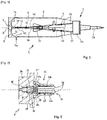
- the figure 3 shows a section taken at the level of the strand 11.
- the strand 11 could also be produced with a heat-shrinkable sheath 12.
- the cords are ignition cords of the type described by patents US5129324 , US5179250 , FR2441598 and EP1092940 .
- Each cord conventionally comprises a plastic tube (for example polyethylene) which contains an oxidation-reducing composition, such as a composition combining boron and potassium nitrate or else aluminum and potassium perchlorate.
- an oxidation-reducing composition such as a composition combining boron and potassium nitrate or else aluminum and potassium perchlorate.
- the cords 10 are individually fixed at their front end by at least one fastening means 13 which is integral with the cartridge 1, for example integral with the projectile 2 itself.
- attachment means 13 can be provided between each cord 10 and the projectile 2.
- the strand 11 is linked to the initiating means 8 by a cable gland 14.
- the figure 2 shows more precisely the structure of the initiation means 8, which comprises a rear block 8a on which is fixed the nut 9 connecting the base, rear block 8a comprising a threaded front extension 8b, of reduced diameter, which receives the tapping of the press packing 14 which has the form of a ring comprising a flared rear part 14a which carries the thread and a front part 14b which defines a bore substantially the diameter of the strand 11 and which ends in a conical bearing surface 14c which presses on the sheath 12 , formed here by adhesive strips surrounding the strand 11.
- the rear part 14a of the stuffing box therefore constitutes a nut engaged on the thread of the extension 8b of the initiating means 8.
- stuffing box 14 allows both radially and axially to immobilize the cords 10 relative to the initiation means 8.
- the device proposed by the invention thus makes it possible to keep the cords 10 slightly stretched between their attachment means 13 and the initiation means 8. A tension is given that is just sufficient to prevent any floating of the cord 10 with respect to the projectile 2.
- the invention also makes it possible to facilitate the packing by compared to known solutions. This solution is therefore well suited to mass production.
- the initiation means 8 comprises an internal axial chamber 16 in which is positioned an ignition relay 17 which is held in place by a support ring 18.
- An igniter 19 is housed in chamber 16, remote from ignition relay 17.
- An ignition button 20 completes the assembly. It is intended to conduct the electric current supplied by the weapon and ensuring the initiation of the igniter 19.
- the toucheau 20 is electrically isolated from the rear block 8a of the initiation means 8. As seen in the figure. figure 2 , the igniter 19 is positioned in a support ring 21 which carries a hole 22 facing the relay 17. There could of course be several relays 17 as needed.
- the strand 11 is therefore fixed near the ignition relay 17. All the cords 10 are simultaneously ignited when the relay 17 is initiated.
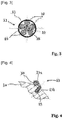
- the figure 4 shows an example of an attachment means 13 on the sabot 2a of the projectile 2.
- This attachment means here consists of a rider 13a integral with a rod 13b which is forced into a hole 15 made in the projectile 2.
- Jumper 13a and rod 13b are made in a single-piece form and in a plastic material, for example polyethylene.
- the jumper 13a has an internal diameter substantially equal to that of the cord 10 and it will have, on its internal face which comes into contact with the cord 10, an indentation (or a bead) ensuring the clamping of the cord 10 and preventing its tearing.
- jumpers could be made in one piece with the connecting ring 6 to allow the cords 10 to be hooked onto the connecting ring 6.
- the invention has been described in its application to a cartridge containing a subcaliber projectile. It is of course possible to implement it with a projectile of a different nature, for example an explosive projectile with caliber.
Landscapes
- Engineering & Computer Science (AREA)
- General Engineering & Computer Science (AREA)
- Chemical & Material Sciences (AREA)
- Organic Chemistry (AREA)
- Air Bags (AREA)
- Aiming, Guidance, Guns With A Light Source, Armor, Camouflage, And Targets (AREA)
- Toys (AREA)
Abstract
Description
- Le domaine technique de l'invention est celui des cartouches comprenant une charge propulsive logée dans un étui et des dispositifs d'allumage de telles charges propulsives.
- Il est connu de réaliser des cartouches dans lesquelles le dispositif d'allumage de la charge propulsive comporte des cordeaux d'allumage énergétiques qui s'étendent entre un moyen d'initiation solidaire d'une partie arrière de l'étui et le projectile.
-
- Les cordeaux d'allumage comprennent le plus souvent un tube en matière plastique renfermant une composition pyrotechnique telle que de la poudre noire ou une composition associant Bore et nitrate de potassium ou encore Aluminium et perchlorate de potassium. Ces cordeaux sont bien connus et décrits en particulier par le brevet
FR2441598 - Les cordeaux d'allumage permettent d'assurer un allumage de la charge propulsive dans une cartouche dont le projectile pénètre profondément à l'intérieur du lit de poudre, en particulier pour un projectile de type flèche avec un barreau de grande longueur. En effet les tubes allumeurs axiaux classiques ne peuvent pas être incorporés avec de tels projectiles.
- Dans les cartouches à cordeaux d'allumage connues les cordeaux s'étendent entre un tube allumeur axial lié au culot et l'étui ou le projectile. En particulier, dans les brevets
US5129324 etUS5179250 , les cordeaux sont disposés le long de la paroi interne de l'étui et ils sont maintenus en place par des étoiles en matière plastique. - Une telle solution autorise des mouvements de pivotement des cordeaux par rapport à l'axe de la cartouche. Des frottements avec les grains de poudre sont alors possibles, pouvant conduire à des incidents pyrotechniques lors des phases de transport des munitions.
- Par ailleurs les étoiles de maintien risquent de créer des imbrûlés et également de perturber la propagation du flux d'allumage.
- La cartouche décrite par le brevet
EP1092940 comporte des cordeaux d'allumage groupés en un toron qui est introduit dans une embase d'allumeur axial. - Mais là encore des mouvements des cordeaux ou du toron par rapport au lit de poudre sont possibles pouvant conduire à des incidents pyrotechniques. De plus, lors des phases de transport, le toron peut s'extraire de l'embase et conduire à un événement catastrophique lors de l'allumage.
- C'est le but de l'invention que de proposer une architecture de cartouche ne comportant pas de tels inconvénients.
- Ainsi la cartouche selon l'invention assure un positionnement fiable des cordeaux d'allumage, garantissant la résistance de la cartouche aux vibrations et chocs dus en particulier au transport.
- Ce positionnement fiable assure par ailleurs un allumage avec des caractéristiques pyrotechniques reproductibles et sans ondes de pression.
- Ainsi l'invention a pour objet une cartouche comprenant un projectile solidaire d'un étui renfermant une charge propulsive et fermé par un culot, un dispositif d'allumage de la charge propulsive comprenant au moins deux cordeaux d'allumage énergétiques s'étendant entre un moyen d'initiation solidaire d'une partie arrière de l'étui et le projectile, cartouche dans laquelle les cordeaux sont réunis au niveau de leur partie arrière de façon à former un toron, cartouche caractérisée en ce que les cordeaux sont fixés par au moins un moyen d'attache solidaire de la cartouche, le toron étant lié au moyen d'initiation par un presse étoupe permettant tout à la fois d'immobiliser radialement et axialement les cordeaux par rapport au moyen d'initiation tout en maintenant les cordeaux tendus entre leur moyen d'attache et le moyen d'initiation.
- Avantageusement, le presse étoupe peut comporter une gaine entourant le toron et sur laquelle vient se positionner un écrou qui s'engage sur un filetage porté par le moyen d'initiation, l'écrou comportant une portée conique s'engageant sur la gaine lors du serrage.
- Le moyen d'initiation peut comporter une chambre interne dans laquelle est positionné au moins un relais d'allumage, le toron se trouvant fixé à proximité du relais d'allumage.
- Selon un mode de réalisation, le moyen d'attache pourra permettre de fixer chaque cordeau au corps du projectile.
- Suivant un mode particulier de réalisation, le projectile est un projectile flèche dont le corps comporte un sabot au calibre entourant un barreau sous calibré, et au moins un moyen d'attache est solidaire du sabot.
- Selon un autre mode de réalisation, au moins un moyen d'attache permet de fixer chaque cordeau à une bague assurant la liaison entre l'étui et le projectile.
- Selon des variantes de réalisation, les moyens d'attache pourront comprendre au moins un cavalier solidaire d'une tige engagée dans le corps du projectile.
- L'invention sera mieux comprise à la lecture de la description qui va suivre de modes particuliers de réalisation, description faite en référence aux dessins annexés et dans lesquels :
- [
Fig. 1 ] montre en coupe longitudinale partielle une cartouche selon un mode de réalisation de l'invention ; - [
Fig. 2 ] est un vue agrandie du moyen d'initiation des cordeaux d'allumage ; - [
Fig. 3 ] est une vue en coupe transversale du toron formé par les cordeaux d'allumage ; - [
Fig. 4 ] montre un exemple d'un moyen d'attache d'un cordeau d'allumage au corps de projectile. - En se reportant à la
figure 1 , une cartouche 1 selon l'invention comprend un projectile 2 solidaire d'un étui 3 qui renferme une charge propulsive 4. L'étui 3 est fermé à sa partie arrière par un culot 5 métallique qui permet d'assurer l'étanchéité au tir dans la chambre de l'arme. A cet effet le culot 5 porte de façon classique une garniture périphérique déformable 5a, par exemple en caoutchouc. - Le projectile 2 est ici un projectile flèche dont le corps comporte un sabot 2a au calibre entourant un barreau 2b sous calibré et stabilisé par un empennage 2c.
- L'étui 3 est un étui combustible réalisé par exemple en nitrocellulose. Il est fixé au projectile 2 par une bague 6 en matière plastique qui assure la liaison entre l'étui 3 et le projectile 2.
- Les brevets
FR2620214 FR2801667 - L'étui 3 est par ailleurs fixé au culot 5 par l'intermédiaire d'une cuvette arrière en matière plastique 7. Une telle cuvette est décrite par le brevet
EP1092939 . Elle comporte des ouvertures 7a régulièrement réparties angulairement autour de l'axe de la cartouche et présente ainsi l'avantage de permettre une mise en place de la charge propulsive 4, par l'arrière de l'étui 3, avant la fixation du culot 5. - Le culot 5 se fixe sur un moyen d'initiation axial 8 qui est attaché à la cuvette 7 comme décrit par le brevet
EP1092939 . Le culot se fixe par un écrou 9 qui est vissé sur le moyen d'initiation 8. - Le dispositif d'allumage de la charge propulsive 4 comporte au moins deux cordeaux d'allumage énergétiques 10 qui s'étendent entre le moyen d'initiation 8 et le projectile 2.
- Comme on le voit sur la
figure 1 , les cordeaux 10 sont réunis au niveau de leur partie arrière de façon à former un toron 11. Cette liaison des cordeaux 10 en un toron unique 11 pourra être réalisée à l'aide de bandes adhésives 12. Lafigure 3 montre une coupe réalisée au niveau du toron 11. Il y a, dans le mode de réalisation qui est ici représenté, six cordeaux 10 identiques, regroupés par une gaine 12 qui est par exemple formée par une ou plusieurs couches de bandes adhésives. On pourrait également réaliser le toron 11 avec une gaine 12 thermorétractable. -
- Chaque cordeau comporte de façon classique un tube en matière plastique (par exemple en polyéthylène) qui renferme une composition oxydo réductrice, telle qu'une composition associant Bore et nitrate de potassium ou bien aluminium et perchlorate de potassium.
- Les cordeaux 10 sont fixés individuellement au niveau de leur extrémité avant par au moins un moyen d'attache 13 qui est solidaire de la cartouche 1, par exemple solidaire du projectile 2 lui-même.
- Il serait possible également d'attacher les extrémités avant des cordeaux 10 à la bague de liaison 6 (mode de réalisation non représenté).
- Comme représenté sur la
figure 1 on pourra prévoir plusieurs moyens d'attache 13 entre chaque cordeau 10 et le projectile 2. - Au niveau de la partie arrière des cordeaux 10, le toron 11 est lié au moyen d'initiation 8 par un presse étoupe 14. La
figure 2 montre plus précisément la structure du moyen d'initiation 8, qui comporte un bloc arrière 8a sur lequel se fixe l'écrou 9 liant le culot, bloc arrière 8a comportant un prolongement avant fileté 8b, de diamètre réduit, qui reçoit le taraudage du presse étoupe 14 qui a la forme d'une bague comportant une partie arrière 14a évasée qui porte le taraudage et une partie avant 14b qui délimite un alésage sensiblement au diamètre du toron 11 et qui se termine par une portée conique 14c qui appuie sur la gaine 12, formée ici par des bandes adhésives entourant le toron 11. La partie arrière 14a du presse étoupe constitue donc un écrou engagé sur le filetage du prolongement 8b du moyen d'initiation 8. - Ainsi le presse étoupe 14 permet tout à la fois d'immobiliser radialement et axialement les cordeaux 10 par rapport au moyen d'initiation 8.
- Le serrage de l'écrou 14a du presse étoupe 14 va exercer une traction sur le toron 11 et la portée conique 14c va pousser la gaine 12, augmentant le serrage et la traction exercée sur les cordeaux 10.
- Le dispositif proposé par l'invention permet ainsi de maintenir les cordeaux 10 légèrement tendus entre leur moyen d'attache 13 et le moyen d'initiation 8. On donnera une tension juste suffisante pour éviter tout flottement du cordeau 10 par rapport au projectile 2.
- Il en résulte une meilleure sécurité pyrotechnique puisque les risques de décrochement des cordeaux 10 ainsi que les frottements de ces cordeaux sur le lit de poudre sont réduits.
- Il en résulte également une fiabilité améliorée de l'allumage de la cartouche et une diminution des imbrûlés. L'invention permet également de faciliter l'encartouchage par rapport aux solutions connues. Cette solution est donc bien adaptée à une production en série.
- Comme on le voit également à la
figure 2 , le moyen d'initiation 8 comporte une chambre axiale interne 16 dans laquelle est positionné un relais d'allumage 17 qui est maintenu en place par une bague support 18. - Un inflammateur 19 est logé dans la chambre 16, à distance du relais d'allumage 17. Un toucheau d'allumage 20 complète le montage. Il est destiné à conduire le courant électrique fourni par l'arme et assurant l'initiation de l'inflammateur 19. Le toucheau 20 est isolé électriquement du bloc arrière 8a du moyen d'initiation 8. Comme on le voit sur la
figure 2 , l'inflammateur 19 est positionné dans une bague support 21 qui porte un trou 22 en regard du relais 17. Il pourrait bien entendu y avoir plusieurs relais 17 en fonction des besoins. - Le toron 11 se trouve donc fixé à proximité du relais d'allumage 17. Tous les cordeaux 10 se trouve allumés simultanément lors de l'initiation du relais 17.
- La
figure 4 montre un exemple d'un moyen d'attache 13 sur le sabot 2a du projectile 2. - Ce moyen d'attache est ici constitué par un cavalier 13a solidaire d'une tige 13b qui est introduite à force dans un trou 15 aménagé dans le projectile 2.
- Cavalier 13a et tige 13b sont réalisés sous une forme monobloc et en une matière plastique, par exemple en Polyéthylène. Le cavalier 13a a un diamètre interne sensiblement égal à celui du cordeau 10 et il comportera, sur sa face interne qui vient en contact avec le cordeau 10, une indentation (ou un bourrelet) assurant le pincement du cordeau 10 et empêchant son arrachement.
- Lors de l'allumage de la charge propulsive 4, les cavaliers 13 sont détruits par la pression des gaz.
- Il est bien entendu possible de combiner plusieurs cavaliers 13 sur un même cordeau 10 et de les associer à des bandes adhésives 12 qui seront utilisées comme moyens d'attache à la place des cavaliers, au niveau des emplacements sur le projectile 2 pour lesquels il n'y a pas suffisamment de matière pour loger une tige 13b.
- A titre de variante, des cavaliers analogues pourront être fabriqués d'une seule pièce avec la bague de liaison 6 pour permettre un accrochage des cordeaux 10 sur la bague de liaison 6.
- L'invention a été décrite dans son application à une cartouche renfermant un projectile sous calibré. Il est bien entendu possible de la mettre en œuvre avec un projectile de nature différente, par exemple un projectile explosif au calibre.
Claims (7)
- Cartouche (1) comprenant un projectile (2) solidaire d'un étui (3) renfermant une charge propulsive (4) et fermé par un culot (5), un dispositif d'allumage de la charge propulsive comprenant au moins deux cordeaux d'allumage énergétiques (10) s'étendant entre un moyen d'initiation (8) solidaire d'une partie arrière de l'étui (3) et le projectile (2), cartouche dans laquelle les cordeaux (10) sont réunis au niveau de leur partie arrière de façon à former un toron (11), cartouche caractérisée en ce que les cordeaux (10) sont fixés par au moins un moyen d'attache (13) solidaire de la cartouche (1), le toron (11) étant lié au moyen d'initiation (8) par un presse étoupe (14) permettant tout à la fois d'immobiliser radialement et axialement les cordeaux (10) par rapport au moyen d'initiation (8) tout en maintenant les cordeaux (10) tendus entre leur moyen d'attache (13) et le moyen d'initiation (8).
- Cartouche selon la revendication 1, caractérisée en ce que le presse étoupe (14) comporte une gaine (12) entourant le toron (11) et sur laquelle vient se positionner un écrou (14a) qui s'engage sur un filetage porté par le moyen d'initiation (8), l'écrou (14a) comportant une portée conique (14c) s'engageant sur la gaine (12) lors du serrage.
- Cartouche selon la revendication 2, caractérisée en ce que le moyen d'initiation (8) comporte une chambre interne (16) dans laquelle est positionné au moins un relais d'allumage (17), le toron (11) se trouvant fixé à proximité du relais d'allumage (17).
- Cartouche selon une des revendications 1 à 3, caractérisée en ce que le moyen d'attache (13) permet de fixer chaque cordeau (10) au corps du projectile (2).
- Cartouche selon la revendication 4, caractérisée en ce que le projectile (2) est un projectile flèche dont le corps comporte un sabot (2a) au calibre entourant un barreau sous calibré (2b), au moins un moyen d'attache (13) étant solidaire du sabot (2a).
- Cartouche selon une des revendications 1 à 3, caractérisée en ce qu'au moins un moyen d'attache (13) permet de fixer chaque cordeau à une bague (6) assurant la liaison entre l'étui (3) et le projectile (2).
- Cartouche selon une des revendications 4 à 6, caractérisée en ce que les moyens d'attache (13) comprennent au moins un cavalier (13a) solidaire d'une tige (13b) engagée dans le corps du projectile (2).
Priority Applications (1)
| Application Number | Priority Date | Filing Date | Title |
|---|---|---|---|
| PL20158974T PL3715776T3 (pl) | 2019-03-27 | 2020-02-24 | Nabój zawierający lont detonujący |
Applications Claiming Priority (1)
| Application Number | Priority Date | Filing Date | Title |
|---|---|---|---|
| FR1903116A FR3094476B1 (fr) | 2019-03-27 | 2019-03-27 | Cartouche comprenant des cordeaux d'allumage |
Publications (2)
| Publication Number | Publication Date |
|---|---|
| EP3715776A1 true EP3715776A1 (fr) | 2020-09-30 |
| EP3715776B1 EP3715776B1 (fr) | 2021-06-02 |
Family
ID=67742616
Family Applications (1)
| Application Number | Title | Priority Date | Filing Date |
|---|---|---|---|
| EP20158974.4A Active EP3715776B1 (fr) | 2019-03-27 | 2020-02-24 | Cartouche comprenant des cordeaux d'allumage |
Country Status (5)
| Country | Link |
|---|---|
| US (1) | US11248884B2 (fr) |
| EP (1) | EP3715776B1 (fr) |
| ES (1) | ES2881813T3 (fr) |
| FR (1) | FR3094476B1 (fr) |
| PL (1) | PL3715776T3 (fr) |
Cited By (1)
| Publication number | Priority date | Publication date | Assignee | Title |
|---|---|---|---|---|
| EP4033198A1 (fr) | 2021-01-26 | 2022-07-27 | Nexter Munitions | Dispositif de liaison entre un moyen d'allumage d'une charge propulsive et un étui combustible d'une munition, étui combustible et rondelle élastique associés à un tel dispositif de liaison |
Families Citing this family (1)
| Publication number | Priority date | Publication date | Assignee | Title |
|---|---|---|---|---|
| FR3113728B1 (fr) * | 2020-09-01 | 2022-12-02 | Nexter Munitions | Douille combustible pour munition |
Citations (8)
| Publication number | Priority date | Publication date | Assignee | Title |
|---|---|---|---|---|
| FR2441598A1 (fr) | 1978-11-20 | 1980-06-13 | Explosive Tech | Meche d'allumage |
| FR2620214A1 (fr) | 1987-09-09 | 1989-03-10 | France Etat Armement | Bague de liaison entre un projectile et une douille |
| EP0344098A1 (fr) * | 1988-05-27 | 1989-11-29 | Atlas Powder Company | Systèmes d'allumage à plusieurs brins |
| US5129324A (en) | 1989-10-19 | 1992-07-14 | Campoli Ralph F | Cartridge assembly |
| US5179250A (en) | 1989-10-19 | 1993-01-12 | Olin Corporation | Segmented cartridge assembly |
| EP1092939A1 (fr) | 1999-10-13 | 2001-04-18 | Giat Industries | Dispositif de fixation d'un culot obturateur sur un étui de munition et culot adapte à un tel dispositif de fixation |
| EP1092940A1 (fr) | 1999-10-13 | 2001-04-18 | Giat Industries | Dispositif d'allumage pour un chargement propulsif |
| FR2801667A1 (fr) | 1999-11-25 | 2001-06-01 | Giat Ind Sa | Dispositif de liaison entre une douille et un projectile et procede de montage d'une ceinture sur un projectile mettant en oeuvre un tel dispositif de liaison |
Family Cites Families (7)
| Publication number | Priority date | Publication date | Assignee | Title |
|---|---|---|---|---|
| DE3033923A1 (de) * | 1980-09-10 | 1982-04-15 | Rheinmetall GmbH, 4000 Düsseldorf | Patronierte munition fuer rohrwaffen mit einer wenigstens teilverbrennbaren treibladungshuelse |
| US5325785A (en) * | 1990-03-13 | 1994-07-05 | The United States Of America As Represented By The Secretary Of The Army | Strand ignition for propellant of shell-coated projectile |
| US5183961A (en) * | 1991-12-09 | 1993-02-02 | Olin Corporation | Extended charge cartridge assembly |
| GB9307799D0 (en) * | 1993-03-15 | 1993-06-02 | Secr Defence | Two part ammunition round |
| FR2827039B1 (fr) * | 2001-07-06 | 2003-11-28 | Giat Ind Sa | Dispositif d'allumage pour un chargement propulsif |
| SE522937C2 (sv) * | 2002-08-08 | 2004-03-16 | Bofors Defence Ab | Hylslöst, komplett skott samt ett sätt att framställa ett dylikt hylslöst, komplett skott |
| FR2849179B1 (fr) * | 2002-12-18 | 2006-06-30 | Giat Ind Sa | Munition sans douille et procede de montage d'une telle munition |
-
2019
- 2019-03-27 FR FR1903116A patent/FR3094476B1/fr active Active
-
2020
- 2020-02-24 ES ES20158974T patent/ES2881813T3/es active Active
- 2020-02-24 EP EP20158974.4A patent/EP3715776B1/fr active Active
- 2020-02-24 PL PL20158974T patent/PL3715776T3/pl unknown
- 2020-03-26 US US16/831,603 patent/US11248884B2/en active Active
Patent Citations (8)
| Publication number | Priority date | Publication date | Assignee | Title |
|---|---|---|---|---|
| FR2441598A1 (fr) | 1978-11-20 | 1980-06-13 | Explosive Tech | Meche d'allumage |
| FR2620214A1 (fr) | 1987-09-09 | 1989-03-10 | France Etat Armement | Bague de liaison entre un projectile et une douille |
| EP0344098A1 (fr) * | 1988-05-27 | 1989-11-29 | Atlas Powder Company | Systèmes d'allumage à plusieurs brins |
| US5129324A (en) | 1989-10-19 | 1992-07-14 | Campoli Ralph F | Cartridge assembly |
| US5179250A (en) | 1989-10-19 | 1993-01-12 | Olin Corporation | Segmented cartridge assembly |
| EP1092939A1 (fr) | 1999-10-13 | 2001-04-18 | Giat Industries | Dispositif de fixation d'un culot obturateur sur un étui de munition et culot adapte à un tel dispositif de fixation |
| EP1092940A1 (fr) | 1999-10-13 | 2001-04-18 | Giat Industries | Dispositif d'allumage pour un chargement propulsif |
| FR2801667A1 (fr) | 1999-11-25 | 2001-06-01 | Giat Ind Sa | Dispositif de liaison entre une douille et un projectile et procede de montage d'une ceinture sur un projectile mettant en oeuvre un tel dispositif de liaison |
Cited By (2)
| Publication number | Priority date | Publication date | Assignee | Title |
|---|---|---|---|---|
| EP4033198A1 (fr) | 2021-01-26 | 2022-07-27 | Nexter Munitions | Dispositif de liaison entre un moyen d'allumage d'une charge propulsive et un étui combustible d'une munition, étui combustible et rondelle élastique associés à un tel dispositif de liaison |
| FR3119231A1 (fr) | 2021-01-26 | 2022-07-29 | Nexter Munitions | Dispositif de liaison entre un moyen d'allumage d'une charge propulsive et un etui combustible d'une munition, etui combustible et rondelle elastique associes a un tel dispositif de liaison. |
Also Published As
| Publication number | Publication date |
|---|---|
| ES2881813T3 (es) | 2021-11-30 |
| FR3094476A1 (fr) | 2020-10-02 |
| US20200378733A1 (en) | 2020-12-03 |
| EP3715776B1 (fr) | 2021-06-02 |
| US11248884B2 (en) | 2022-02-15 |
| FR3094476B1 (fr) | 2021-02-19 |
| PL3715776T3 (pl) | 2021-09-13 |
Similar Documents
| Publication | Publication Date | Title |
|---|---|---|
| EP1092940B1 (fr) | Dispositif d'allumage pour un chargement propulsif | |
| CH634142A5 (fr) | Mecanisme de lancement d'un projectile sous-calibre. | |
| EP3715776B1 (fr) | Cartouche comprenant des cordeaux d'allumage | |
| EP0293295A1 (fr) | Perfectionnements apportés aux projectiles perforants | |
| EP0307307B1 (fr) | Bague de liaison entre un projectile et une douille | |
| FR2685468A1 (fr) | Tube douille pour grenade a fusil pouvant retenir les fragments de la balle. | |
| EP1181498B1 (fr) | Tube allumeur pour une munition d'artillerie | |
| FR2622687A1 (fr) | Chargement propulsif pour munition comportant un projectile empenne ainsi que son procede de realisation | |
| EP0659264B1 (fr) | Dispositif d'etancheite aux gaz de propulsion pour munitions d'artillerie | |
| EP0048644B1 (fr) | Projectile empenné du type flèche | |
| EP0640204B1 (fr) | Munition de type telescopee | |
| EP0594482B1 (fr) | Boîtier pour charge propulsive | |
| EP2620737B1 (fr) | Munition non létale | |
| EP0401114A1 (fr) | Dispositif de maintien d'un projectile relativement à l'enveloppe d'une munition télescopée | |
| FR2671622A1 (fr) | Projectile avec coiffe rapportee. | |
| EP1693646A1 (fr) | Ceinture d'étanchéité pour projectile d'artillerie | |
| EP0281462B1 (fr) | Munition notamment pour artillerie comportant un projectile et une douille | |
| WO2022049465A1 (fr) | Douille combustible pour munition | |
| EP2219007B1 (fr) | Procédé de fixation d'un projectile en matière plastique sur un étui métallique et projectile permettant la mise en oeuvre de ce procédé | |
| FR2927417A1 (fr) | Obus de dispersion de projectiles | |
| EP1106959A1 (fr) | Tube allumeur pour munition d'artillerie | |
| FR2978821A1 (fr) | Obus d'artillerie a portee accrue | |
| FR2915563A1 (fr) | Projectile generateur d'eclats | |
| FR2520862A1 (fr) | Mine anti-personnel a effet dirige | |
| FR2677749A1 (fr) | Dispositif a projectiles comportant deux projectiles a effet cinetique sous-calibres. |
Legal Events
| Date | Code | Title | Description |
|---|---|---|---|
| PUAI | Public reference made under article 153(3) epc to a published international application that has entered the european phase |
Free format text: ORIGINAL CODE: 0009012 |
|
| STAA | Information on the status of an ep patent application or granted ep patent |
Free format text: STATUS: THE APPLICATION HAS BEEN PUBLISHED |
|
| AK | Designated contracting states |
Kind code of ref document: A1 Designated state(s): AL AT BE BG CH CY CZ DE DK EE ES FI FR GB GR HR HU IE IS IT LI LT LU LV MC MK MT NL NO PL PT RO RS SE SI SK SM TR |
|
| AX | Request for extension of the european patent |
Extension state: BA ME |
|
| STAA | Information on the status of an ep patent application or granted ep patent |
Free format text: STATUS: REQUEST FOR EXAMINATION WAS MADE |
|
| 17P | Request for examination filed |
Effective date: 20201020 |
|
| RBV | Designated contracting states (corrected) |
Designated state(s): AL AT BE BG CH CY CZ DE DK EE ES FI FR GB GR HR HU IE IS IT LI LT LU LV MC MK MT NL NO PL PT RO RS SE SI SK SM TR |
|
| RIN1 | Information on inventor provided before grant (corrected) |
Inventor name: ORSAT, GUILLAUME Inventor name: THEILLIER, LUCIE Inventor name: BARRES, DAVID Inventor name: COTET, STEPHANE |
|
| GRAP | Despatch of communication of intention to grant a patent |
Free format text: ORIGINAL CODE: EPIDOSNIGR1 |
|
| STAA | Information on the status of an ep patent application or granted ep patent |
Free format text: STATUS: GRANT OF PATENT IS INTENDED |
|
| RIC1 | Information provided on ipc code assigned before grant |
Ipc: F42B 12/06 20060101ALN20210129BHEP Ipc: F42C 19/08 20060101AFI20210129BHEP Ipc: F42B 14/06 20060101ALN20210129BHEP |
|
| INTG | Intention to grant announced |
Effective date: 20210215 |
|
| GRAS | Grant fee paid |
Free format text: ORIGINAL CODE: EPIDOSNIGR3 |
|
| GRAA | (expected) grant |
Free format text: ORIGINAL CODE: 0009210 |
|
| STAA | Information on the status of an ep patent application or granted ep patent |
Free format text: STATUS: THE PATENT HAS BEEN GRANTED |
|
| REG | Reference to a national code |
Ref country code: CH Ref legal event code: EP |
|
| AK | Designated contracting states |
Kind code of ref document: B1 Designated state(s): AL AT BE BG CH CY CZ DE DK EE ES FI FR GB GR HR HU IE IS IT LI LT LU LV MC MK MT NL NO PL PT RO RS SE SI SK SM TR |
|
| REG | Reference to a national code |
Ref country code: GB Ref legal event code: FG4D Free format text: NOT ENGLISH |
|
| REG | Reference to a national code |
Ref country code: AT Ref legal event code: REF Ref document number: 1398859 Country of ref document: AT Kind code of ref document: T Effective date: 20210615 |
|
| REG | Reference to a national code |
Ref country code: IE Ref legal event code: FG4D Free format text: LANGUAGE OF EP DOCUMENT: FRENCH |
|
| REG | Reference to a national code |
Ref country code: DE Ref legal event code: R096 Ref document number: 602020000125 Country of ref document: DE |
|
| REG | Reference to a national code |
Ref country code: SE Ref legal event code: TRGR |
|
| REG | Reference to a national code |
Ref country code: LT Ref legal event code: MG9D |
|
| PG25 | Lapsed in a contracting state [announced via postgrant information from national office to epo] |
Ref country code: FI Free format text: LAPSE BECAUSE OF FAILURE TO SUBMIT A TRANSLATION OF THE DESCRIPTION OR TO PAY THE FEE WITHIN THE PRESCRIBED TIME-LIMIT Effective date: 20210602 Ref country code: LT Free format text: LAPSE BECAUSE OF FAILURE TO SUBMIT A TRANSLATION OF THE DESCRIPTION OR TO PAY THE FEE WITHIN THE PRESCRIBED TIME-LIMIT Effective date: 20210602 Ref country code: HR Free format text: LAPSE BECAUSE OF FAILURE TO SUBMIT A TRANSLATION OF THE DESCRIPTION OR TO PAY THE FEE WITHIN THE PRESCRIBED TIME-LIMIT Effective date: 20210602 Ref country code: BG Free format text: LAPSE BECAUSE OF FAILURE TO SUBMIT A TRANSLATION OF THE DESCRIPTION OR TO PAY THE FEE WITHIN THE PRESCRIBED TIME-LIMIT Effective date: 20210902 |
|
| REG | Reference to a national code |
Ref country code: NO Ref legal event code: T2 Effective date: 20210602 |
|
| REG | Reference to a national code |
Ref country code: NL Ref legal event code: MP Effective date: 20210602 |
|
| REG | Reference to a national code |
Ref country code: AT Ref legal event code: MK05 Ref document number: 1398859 Country of ref document: AT Kind code of ref document: T Effective date: 20210602 |
|
| PG25 | Lapsed in a contracting state [announced via postgrant information from national office to epo] |
Ref country code: GR Free format text: LAPSE BECAUSE OF FAILURE TO SUBMIT A TRANSLATION OF THE DESCRIPTION OR TO PAY THE FEE WITHIN THE PRESCRIBED TIME-LIMIT Effective date: 20210903 Ref country code: RS Free format text: LAPSE BECAUSE OF FAILURE TO SUBMIT A TRANSLATION OF THE DESCRIPTION OR TO PAY THE FEE WITHIN THE PRESCRIBED TIME-LIMIT Effective date: 20210602 Ref country code: LV Free format text: LAPSE BECAUSE OF FAILURE TO SUBMIT A TRANSLATION OF THE DESCRIPTION OR TO PAY THE FEE WITHIN THE PRESCRIBED TIME-LIMIT Effective date: 20210602 |
|
| REG | Reference to a national code |
Ref country code: ES Ref legal event code: FG2A Ref document number: 2881813 Country of ref document: ES Kind code of ref document: T3 Effective date: 20211130 |
|
| PG25 | Lapsed in a contracting state [announced via postgrant information from national office to epo] |
Ref country code: EE Free format text: LAPSE BECAUSE OF FAILURE TO SUBMIT A TRANSLATION OF THE DESCRIPTION OR TO PAY THE FEE WITHIN THE PRESCRIBED TIME-LIMIT Effective date: 20210602 Ref country code: SK Free format text: LAPSE BECAUSE OF FAILURE TO SUBMIT A TRANSLATION OF THE DESCRIPTION OR TO PAY THE FEE WITHIN THE PRESCRIBED TIME-LIMIT Effective date: 20210602 Ref country code: AT Free format text: LAPSE BECAUSE OF FAILURE TO SUBMIT A TRANSLATION OF THE DESCRIPTION OR TO PAY THE FEE WITHIN THE PRESCRIBED TIME-LIMIT Effective date: 20210602 Ref country code: SM Free format text: LAPSE BECAUSE OF FAILURE TO SUBMIT A TRANSLATION OF THE DESCRIPTION OR TO PAY THE FEE WITHIN THE PRESCRIBED TIME-LIMIT Effective date: 20210602 Ref country code: RO Free format text: LAPSE BECAUSE OF FAILURE TO SUBMIT A TRANSLATION OF THE DESCRIPTION OR TO PAY THE FEE WITHIN THE PRESCRIBED TIME-LIMIT Effective date: 20210602 Ref country code: NL Free format text: LAPSE BECAUSE OF FAILURE TO SUBMIT A TRANSLATION OF THE DESCRIPTION OR TO PAY THE FEE WITHIN THE PRESCRIBED TIME-LIMIT Effective date: 20210602 Ref country code: PT Free format text: LAPSE BECAUSE OF FAILURE TO SUBMIT A TRANSLATION OF THE DESCRIPTION OR TO PAY THE FEE WITHIN THE PRESCRIBED TIME-LIMIT Effective date: 20211004 |
|
| REG | Reference to a national code |
Ref country code: DE Ref legal event code: R097 Ref document number: 602020000125 Country of ref document: DE |
|
| PLBE | No opposition filed within time limit |
Free format text: ORIGINAL CODE: 0009261 |
|
| STAA | Information on the status of an ep patent application or granted ep patent |
Free format text: STATUS: NO OPPOSITION FILED WITHIN TIME LIMIT |
|
| PG25 | Lapsed in a contracting state [announced via postgrant information from national office to epo] |
Ref country code: DK Free format text: LAPSE BECAUSE OF FAILURE TO SUBMIT A TRANSLATION OF THE DESCRIPTION OR TO PAY THE FEE WITHIN THE PRESCRIBED TIME-LIMIT Effective date: 20210602 |
|
| 26N | No opposition filed |
Effective date: 20220303 |
|
| PG25 | Lapsed in a contracting state [announced via postgrant information from national office to epo] |
Ref country code: AL Free format text: LAPSE BECAUSE OF FAILURE TO SUBMIT A TRANSLATION OF THE DESCRIPTION OR TO PAY THE FEE WITHIN THE PRESCRIBED TIME-LIMIT Effective date: 20210602 |
|
| PG25 | Lapsed in a contracting state [announced via postgrant information from national office to epo] |
Ref country code: IT Free format text: LAPSE BECAUSE OF FAILURE TO SUBMIT A TRANSLATION OF THE DESCRIPTION OR TO PAY THE FEE WITHIN THE PRESCRIBED TIME-LIMIT Effective date: 20210602 |
|
| PG25 | Lapsed in a contracting state [announced via postgrant information from national office to epo] |
Ref country code: MC Free format text: LAPSE BECAUSE OF FAILURE TO SUBMIT A TRANSLATION OF THE DESCRIPTION OR TO PAY THE FEE WITHIN THE PRESCRIBED TIME-LIMIT Effective date: 20210602 |
|
| REG | Reference to a national code |
Ref country code: BE Ref legal event code: MM Effective date: 20220228 |
|
| PG25 | Lapsed in a contracting state [announced via postgrant information from national office to epo] |
Ref country code: LU Free format text: LAPSE BECAUSE OF NON-PAYMENT OF DUE FEES Effective date: 20220224 |
|
| PG25 | Lapsed in a contracting state [announced via postgrant information from national office to epo] |
Ref country code: IE Free format text: LAPSE BECAUSE OF NON-PAYMENT OF DUE FEES Effective date: 20220224 |
|
| PG25 | Lapsed in a contracting state [announced via postgrant information from national office to epo] |
Ref country code: BE Free format text: LAPSE BECAUSE OF NON-PAYMENT OF DUE FEES Effective date: 20220228 |
|
| PGFP | Annual fee paid to national office [announced via postgrant information from national office to epo] |
Ref country code: NO Payment date: 20230120 Year of fee payment: 4 Ref country code: FR Payment date: 20230119 Year of fee payment: 4 |
|
| PGFP | Annual fee paid to national office [announced via postgrant information from national office to epo] |
Ref country code: TR Payment date: 20230124 Year of fee payment: 4 Ref country code: SE Payment date: 20230119 Year of fee payment: 4 Ref country code: PL Payment date: 20230123 Year of fee payment: 4 |
|
| P01 | Opt-out of the competence of the unified patent court (upc) registered |
Effective date: 20231212 |
|
| PGFP | Annual fee paid to national office [announced via postgrant information from national office to epo] |
Ref country code: ES Payment date: 20240301 Year of fee payment: 5 |
|
| PG25 | Lapsed in a contracting state [announced via postgrant information from national office to epo] |
Ref country code: MK Free format text: LAPSE BECAUSE OF FAILURE TO SUBMIT A TRANSLATION OF THE DESCRIPTION OR TO PAY THE FEE WITHIN THE PRESCRIBED TIME-LIMIT Effective date: 20210602 Ref country code: CY Free format text: LAPSE BECAUSE OF FAILURE TO SUBMIT A TRANSLATION OF THE DESCRIPTION OR TO PAY THE FEE WITHIN THE PRESCRIBED TIME-LIMIT Effective date: 20210602 |
|
| PGFP | Annual fee paid to national office [announced via postgrant information from national office to epo] |
Ref country code: DE Payment date: 20240123 Year of fee payment: 5 Ref country code: CZ Payment date: 20240125 Year of fee payment: 5 Ref country code: CH Payment date: 20240301 Year of fee payment: 5 Ref country code: GB Payment date: 20240123 Year of fee payment: 5 |