EP3715568A1 - Nockentürschliesser - Google Patents
Nockentürschliesser Download PDFInfo
- Publication number
- EP3715568A1 EP3715568A1 EP19170817.1A EP19170817A EP3715568A1 EP 3715568 A1 EP3715568 A1 EP 3715568A1 EP 19170817 A EP19170817 A EP 19170817A EP 3715568 A1 EP3715568 A1 EP 3715568A1
- Authority
- EP
- European Patent Office
- Prior art keywords
- piston
- housing
- passage
- axial passage
- shaft
- Prior art date
- Legal status (The legal status is an assumption and is not a legal conclusion. Google has not performed a legal analysis and makes no representation as to the accuracy of the status listed.)
- Granted
Links
- 238000007789 sealing Methods 0.000 claims abstract description 19
- 238000004891 communication Methods 0.000 claims abstract description 10
- 230000004308 accommodation Effects 0.000 claims description 9
- 230000007704 transition Effects 0.000 claims description 9
- 230000002093 peripheral effect Effects 0.000 claims description 3
- 239000011521 glass Substances 0.000 description 23
- 238000013461 design Methods 0.000 description 4
- 238000000034 method Methods 0.000 description 4
- 230000008569 process Effects 0.000 description 4
- 230000008901 benefit Effects 0.000 description 2
- 230000009471 action Effects 0.000 description 1
- 230000008859 change Effects 0.000 description 1
- 238000013016 damping Methods 0.000 description 1
- 238000011161 development Methods 0.000 description 1
- 230000000694 effects Effects 0.000 description 1
- 239000000446 fuel Substances 0.000 description 1
- 230000006872 improvement Effects 0.000 description 1
- 238000012986 modification Methods 0.000 description 1
- 230000004048 modification Effects 0.000 description 1
- 230000007480 spreading Effects 0.000 description 1
Images


Classifications
-
- E—FIXED CONSTRUCTIONS
- E05—LOCKS; KEYS; WINDOW OR DOOR FITTINGS; SAFES
- E05F—DEVICES FOR MOVING WINGS INTO OPEN OR CLOSED POSITION; CHECKS FOR WINGS; WING FITTINGS NOT OTHERWISE PROVIDED FOR, CONCERNED WITH THE FUNCTIONING OF THE WING
- E05F3/00—Closers or openers with braking devices, e.g. checks; Construction of pneumatic or liquid braking devices
- E05F3/18—Closers or openers with braking devices, e.g. checks; Construction of pneumatic or liquid braking devices with counteracting springs
-
- E—FIXED CONSTRUCTIONS
- E05—LOCKS; KEYS; WINDOW OR DOOR FITTINGS; SAFES
- E05F—DEVICES FOR MOVING WINGS INTO OPEN OR CLOSED POSITION; CHECKS FOR WINGS; WING FITTINGS NOT OTHERWISE PROVIDED FOR, CONCERNED WITH THE FUNCTIONING OF THE WING
- E05F3/00—Closers or openers with braking devices, e.g. checks; Construction of pneumatic or liquid braking devices
- E05F3/22—Additional arrangements for closers, e.g. for holding the wing in opened or other position
- E05F3/224—Additional arrangements for closers, e.g. for holding the wing in opened or other position for assisting in opening the wing
-
- E—FIXED CONSTRUCTIONS
- E05—LOCKS; KEYS; WINDOW OR DOOR FITTINGS; SAFES
- E05F—DEVICES FOR MOVING WINGS INTO OPEN OR CLOSED POSITION; CHECKS FOR WINGS; WING FITTINGS NOT OTHERWISE PROVIDED FOR, CONCERNED WITH THE FUNCTIONING OF THE WING
- E05F1/00—Closers or openers for wings, not otherwise provided for in this subclass
- E05F1/08—Closers or openers for wings, not otherwise provided for in this subclass spring-actuated, e.g. for horizontally sliding wings
- E05F1/10—Closers or openers for wings, not otherwise provided for in this subclass spring-actuated, e.g. for horizontally sliding wings for swinging wings, e.g. counterbalance
- E05F1/1041—Closers or openers for wings, not otherwise provided for in this subclass spring-actuated, e.g. for horizontally sliding wings for swinging wings, e.g. counterbalance with a coil spring perpendicular to the pivot axis
- E05F1/105—Closers or openers for wings, not otherwise provided for in this subclass spring-actuated, e.g. for horizontally sliding wings for swinging wings, e.g. counterbalance with a coil spring perpendicular to the pivot axis with a compression spring
-
- E—FIXED CONSTRUCTIONS
- E05—LOCKS; KEYS; WINDOW OR DOOR FITTINGS; SAFES
- E05F—DEVICES FOR MOVING WINGS INTO OPEN OR CLOSED POSITION; CHECKS FOR WINGS; WING FITTINGS NOT OTHERWISE PROVIDED FOR, CONCERNED WITH THE FUNCTIONING OF THE WING
- E05F3/00—Closers or openers with braking devices, e.g. checks; Construction of pneumatic or liquid braking devices
- E05F3/04—Closers or openers with braking devices, e.g. checks; Construction of pneumatic or liquid braking devices with liquid piston brakes
- E05F3/10—Closers or openers with braking devices, e.g. checks; Construction of pneumatic or liquid braking devices with liquid piston brakes with a spring, other than a torsion spring, and a piston, the axes of which are the same or lie in the same direction
- E05F3/104—Closers or openers with braking devices, e.g. checks; Construction of pneumatic or liquid braking devices with liquid piston brakes with a spring, other than a torsion spring, and a piston, the axes of which are the same or lie in the same direction with cam-and-slide transmission between driving shaft and piston within the closer housing
-
- E—FIXED CONSTRUCTIONS
- E05—LOCKS; KEYS; WINDOW OR DOOR FITTINGS; SAFES
- E05F—DEVICES FOR MOVING WINGS INTO OPEN OR CLOSED POSITION; CHECKS FOR WINGS; WING FITTINGS NOT OTHERWISE PROVIDED FOR, CONCERNED WITH THE FUNCTIONING OF THE WING
- E05F3/00—Closers or openers with braking devices, e.g. checks; Construction of pneumatic or liquid braking devices
- E05F3/22—Additional arrangements for closers, e.g. for holding the wing in opened or other position
- E05F3/223—Hydraulic power-locks, e.g. with electrically operated hydraulic valves
-
- E—FIXED CONSTRUCTIONS
- E05—LOCKS; KEYS; WINDOW OR DOOR FITTINGS; SAFES
- E05Y—INDEXING SCHEME ASSOCIATED WITH SUBCLASSES E05D AND E05F, RELATING TO CONSTRUCTION ELEMENTS, ELECTRIC CONTROL, POWER SUPPLY, POWER SIGNAL OR TRANSMISSION, USER INTERFACES, MOUNTING OR COUPLING, DETAILS, ACCESSORIES, AUXILIARY OPERATIONS NOT OTHERWISE PROVIDED FOR, APPLICATION THEREOF
- E05Y2201/00—Constructional elements; Accessories therefor
- E05Y2201/40—Motors; Magnets; Springs; Weights; Accessories therefor
- E05Y2201/404—Function thereof
- E05Y2201/408—Function thereof for braking
-
- E—FIXED CONSTRUCTIONS
- E05—LOCKS; KEYS; WINDOW OR DOOR FITTINGS; SAFES
- E05Y—INDEXING SCHEME ASSOCIATED WITH SUBCLASSES E05D AND E05F, RELATING TO CONSTRUCTION ELEMENTS, ELECTRIC CONTROL, POWER SUPPLY, POWER SIGNAL OR TRANSMISSION, USER INTERFACES, MOUNTING OR COUPLING, DETAILS, ACCESSORIES, AUXILIARY OPERATIONS NOT OTHERWISE PROVIDED FOR, APPLICATION THEREOF
- E05Y2201/00—Constructional elements; Accessories therefor
- E05Y2201/40—Motors; Magnets; Springs; Weights; Accessories therefor
- E05Y2201/43—Motors
- E05Y2201/448—Fluid motors; Details thereof
- E05Y2201/456—Pistons
-
- E—FIXED CONSTRUCTIONS
- E05—LOCKS; KEYS; WINDOW OR DOOR FITTINGS; SAFES
- E05Y—INDEXING SCHEME ASSOCIATED WITH SUBCLASSES E05D AND E05F, RELATING TO CONSTRUCTION ELEMENTS, ELECTRIC CONTROL, POWER SUPPLY, POWER SIGNAL OR TRANSMISSION, USER INTERFACES, MOUNTING OR COUPLING, DETAILS, ACCESSORIES, AUXILIARY OPERATIONS NOT OTHERWISE PROVIDED FOR, APPLICATION THEREOF
- E05Y2201/00—Constructional elements; Accessories therefor
- E05Y2201/40—Motors; Magnets; Springs; Weights; Accessories therefor
- E05Y2201/47—Springs
- E05Y2201/474—Compression springs
-
- E—FIXED CONSTRUCTIONS
- E05—LOCKS; KEYS; WINDOW OR DOOR FITTINGS; SAFES
- E05Y—INDEXING SCHEME ASSOCIATED WITH SUBCLASSES E05D AND E05F, RELATING TO CONSTRUCTION ELEMENTS, ELECTRIC CONTROL, POWER SUPPLY, POWER SIGNAL OR TRANSMISSION, USER INTERFACES, MOUNTING OR COUPLING, DETAILS, ACCESSORIES, AUXILIARY OPERATIONS NOT OTHERWISE PROVIDED FOR, APPLICATION THEREOF
- E05Y2201/00—Constructional elements; Accessories therefor
- E05Y2201/60—Suspension or transmission members; Accessories therefor
- E05Y2201/622—Suspension or transmission members elements
- E05Y2201/638—Cams; Ramps
-
- E—FIXED CONSTRUCTIONS
- E05—LOCKS; KEYS; WINDOW OR DOOR FITTINGS; SAFES
- E05Y—INDEXING SCHEME ASSOCIATED WITH SUBCLASSES E05D AND E05F, RELATING TO CONSTRUCTION ELEMENTS, ELECTRIC CONTROL, POWER SUPPLY, POWER SIGNAL OR TRANSMISSION, USER INTERFACES, MOUNTING OR COUPLING, DETAILS, ACCESSORIES, AUXILIARY OPERATIONS NOT OTHERWISE PROVIDED FOR, APPLICATION THEREOF
- E05Y2201/00—Constructional elements; Accessories therefor
- E05Y2201/60—Suspension or transmission members; Accessories therefor
- E05Y2201/622—Suspension or transmission members elements
- E05Y2201/682—Pins
-
- E—FIXED CONSTRUCTIONS
- E05—LOCKS; KEYS; WINDOW OR DOOR FITTINGS; SAFES
- E05Y—INDEXING SCHEME ASSOCIATED WITH SUBCLASSES E05D AND E05F, RELATING TO CONSTRUCTION ELEMENTS, ELECTRIC CONTROL, POWER SUPPLY, POWER SIGNAL OR TRANSMISSION, USER INTERFACES, MOUNTING OR COUPLING, DETAILS, ACCESSORIES, AUXILIARY OPERATIONS NOT OTHERWISE PROVIDED FOR, APPLICATION THEREOF
- E05Y2201/00—Constructional elements; Accessories therefor
- E05Y2201/60—Suspension or transmission members; Accessories therefor
- E05Y2201/622—Suspension or transmission members elements
- E05Y2201/688—Rollers
-
- E—FIXED CONSTRUCTIONS
- E05—LOCKS; KEYS; WINDOW OR DOOR FITTINGS; SAFES
- E05Y—INDEXING SCHEME ASSOCIATED WITH SUBCLASSES E05D AND E05F, RELATING TO CONSTRUCTION ELEMENTS, ELECTRIC CONTROL, POWER SUPPLY, POWER SIGNAL OR TRANSMISSION, USER INTERFACES, MOUNTING OR COUPLING, DETAILS, ACCESSORIES, AUXILIARY OPERATIONS NOT OTHERWISE PROVIDED FOR, APPLICATION THEREOF
- E05Y2201/00—Constructional elements; Accessories therefor
- E05Y2201/60—Suspension or transmission members; Accessories therefor
- E05Y2201/622—Suspension or transmission members elements
- E05Y2201/706—Shafts
-
- E—FIXED CONSTRUCTIONS
- E05—LOCKS; KEYS; WINDOW OR DOOR FITTINGS; SAFES
- E05Y—INDEXING SCHEME ASSOCIATED WITH SUBCLASSES E05D AND E05F, RELATING TO CONSTRUCTION ELEMENTS, ELECTRIC CONTROL, POWER SUPPLY, POWER SIGNAL OR TRANSMISSION, USER INTERFACES, MOUNTING OR COUPLING, DETAILS, ACCESSORIES, AUXILIARY OPERATIONS NOT OTHERWISE PROVIDED FOR, APPLICATION THEREOF
- E05Y2800/00—Details, accessories and auxiliary operations not otherwise provided for
- E05Y2800/26—Form or shape
- E05Y2800/298—Form or shape having indentations
-
- E—FIXED CONSTRUCTIONS
- E05—LOCKS; KEYS; WINDOW OR DOOR FITTINGS; SAFES
- E05Y—INDEXING SCHEME ASSOCIATED WITH SUBCLASSES E05D AND E05F, RELATING TO CONSTRUCTION ELEMENTS, ELECTRIC CONTROL, POWER SUPPLY, POWER SIGNAL OR TRANSMISSION, USER INTERFACES, MOUNTING OR COUPLING, DETAILS, ACCESSORIES, AUXILIARY OPERATIONS NOT OTHERWISE PROVIDED FOR, APPLICATION THEREOF
- E05Y2900/00—Application of doors, windows, wings or fittings thereof
- E05Y2900/10—Application of doors, windows, wings or fittings thereof for buildings or parts thereof
- E05Y2900/13—Type of wing
- E05Y2900/132—Doors
Definitions
- the invention relates to a door closer, in particular to a cam type door closer capable of compensating for a gap, which can stabilize the closing speed of the door by a compensation design of the piston during the closing process.
- Taiwan Patent No. 1495780 a conventional door closer is used to assist the door to be slowly and automatically closed after being opened, thereby maintaining the stability and closed state of the indoor environment.
- the present invention has been accomplished under the circumstances in view. It is the main object of the present invention to provide a cam type door closer, which has the effect of controlling the closing speed of the glass door in the whole process and has the advantage of positioning the glass door at a predetermined pivot angle.
- a cam type door closer comprises a housing, a first piston set, a second piston set, and a drive shaft assembly.
- the housing comprises an axial passage and a longitudinal passage in communication with the axial passage.
- the axial passage extends perpendicular to the longitudinal passage and runs through two opposite sides of the housing.
- the first piston set is mounted in the axial passage of the housing, comprising a first piston, a roller, a plug pin, a first spring and a first sealing cap.
- the first piston comprises an open chamber, a shaft hole and an elongated slot respectively disposed in communication with each other.
- the open chamber is located in a middle part of the first piston.
- the shaft hole is located in a distal end of the first piston.
- the elongated slot is disposed above the open chamber.
- the first spring is mounted in the axial passage of the housing with one end thereof stopped against the first piston and an opposite end thereof stopped against the first sealing cap.
- the first sealing cap is mounted in the housing to seal one end of the axial passage.
- the second piston set is mounted in the axial passage of the housing, comprising a second piston, a gap compensation device, a second spring and a second sealing cap.
- the second piston is movably mounted in the shaft hole of the first piston, comprising a large diameter passage and a small diameter passage in communication with each other.
- the gap compensation device is mounted in the large diameter passage of the second piston.
- the second spring is mounted in the axial passage of the housing with one end thereof stopped against the second piston and an opposite end thereof stopped against the second sealing cap.
- the second sealing cap is mounted in the housing to seal an opposite end of the axial passage.
- the drive shaft assembly is rotatably inserted into the longitudinal passage of the housing, comprising a shaft and an eccentric cam.
- the eccentric cam is located on the shaft with one side thereof stopped against the roller of the first piston set and an opposite side thereof stopped against the second piston of the second piston set.
- the housing further comprises a recess located above the longitudinal passage.
- the shaft comprises a latching segment, a connecting segment and a transition segment between the latching segment and the connecting segment.
- the eccentric cam is mounted on the shaft between the transition segment and the connecting segment within the open chamber of the first piston.
- the connecting segment of the shaft is inserted through the elongated slot of the first piston into the recess of the housing.
- the drive shaft assembly further comprises an upper bushing, a gasket and a lower bushing set.
- the upper bushing and the gasket are mounted in said recess of the housing.
- the connecting segment of the shaft is inserted into the upper bushing.
- the lower bushing set is mounted on the transition segment of the shaft to enhance the pivoting smoothness of the drive shaft assembly.
- the gap compensation device of the second piston set comprises a locating ring, a sleeve, a plug, an elastic member and a locating pin.
- the locating ring is threaded into the large diameter passage of the second piston.
- the sleeve comprises a sleeve body and a flange at a distal end of the sleeve body.
- the sleeve body is inserted into the locating ring.
- the flange is stopped at an end edge of the locating ring.
- the sleeve body of the sleeve comprises an accommodating space and a small passage coaxially communicated with each other.
- the plug and the elastic member are sequentially mounted in the accommodating space of the sleeve body.
- the plug has one end thereof facing toward the small passage of the sleeve body and an opposite end thereof stopped against the elastic member.
- the locating pin is inserted into the sleeve body to pass through the accommodating space for stopping the elastic member. It is used to adjust the fuel supply of the hydraulic piston so as to improve the opening and closing quality and control the closing speed.
- the eccentric cam comprises two positioning grooves.
- One positioning groove is adapted for stopping against the roller of the first piston set when the housing is biased to a first predetermined pivot angle.
- the other positioning groove is adapted for stopping against the second piston of the second piston set when the housing is biased to a second predetermined pivot angle.
- the eccentric cam comprises a concave arc portion adapted for stopping against the second piston of the second piston set when the housing is biased to a third predetermined pivot angle.
- the cam type door closer further comprises a locating block.
- the locating block comprises a mounting plate, a plurality of adjusting members and an adjustment plate.
- the mounting plate is affixed to the floor.
- the mounting plate comprises an accommodation chamber, and a plurality of adjusting holes on a peripheral wall thereof in communication with the accommodation chamber.
- the adjusting members are respectively movably mounted in the adjusting holes.
- the adjustment plate is mounted in the accommodation chamber of the mounting plate and connected to the shaft of the drive shaft assembly and stoppable by the adjusting members to move relative to the mounting plate in adjusting the deviation of the door so that the door can be accurately closed.
- the first spring of the first piston set and the second spring of the second piston set will each provide a moderate pressure to the first piston and the second piston against the roller and the second piston and provides resistance to the eccentric cam of the drive shaft assembly in the whole door closing process, so that the closing speed of the glass door can be controlled at all times, which can reduce the damage of the internal components of the door closer.
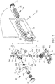
- the cam type door closer 10 comprises a housing 20 , a first piston set 30 , a second piston set 40 , a drive shaft assembly 50 and a locating block 60 .
- the housing 20 is an elongated member, having an axial passage 21 , a longitudinal passage 23 and a recess 25 , which are connected to each other.
- the axial passage 21 is perpendicular to the longitudinal passage 23 .
- the axial passage 21 runs through two opposite sides of the housing 20 .
- the recess 25 is located above the longitudinal passage 23 .
- the first piston set 30 is located in one side of the axial passage 21 of the housing 20 , comprising a first piston 31 , a roller 32 , a plug pin 33 , a first spring 34 and a first sealing cap 35 .
- the first piston 31 is provided with an open chamber 311 , a shaft hole 312 and an elongated slot 313 , which are connected to each other.
- the open chamber 311 is located in the middle of the first piston 31 .
- the shaft hole 312 is at the end of the first piston 31 .
- the elongated slot 313 is located above the open chamber 311 .
- the first spring 34 is mounted in the axial passage 21 of the housing 20 with one end thereof stopped against the first piston 31 and an opposite end thereof stopped against the first sealing cap 35 .
- the first sealing cap 35 is mounted in the housing 20 to seal one end of the axial passage 21 .
- the second piston set 40 is located in an opposite side of the axial passage 21 of the housing 20 , comprising a second piston 41 , a gap compensation device 42 , a second spring 43 and a second sealing cap 44 .
- the second piston 41 is movably mounted in the shaft hole 312 of the first piston 31 .
- the second piston 41 is provided with a large diameter passage 411 and a small diameter passage 412 , which are connected to each other.
- the gap compensation device 42 is mounted in the large diameter passage 411 of the second piston 41 .
- the second spring 43 is mounted in the axial passage 21 of the housing 20 with one end thereof stopped against the second piston 41 , second spring 43 and an opposite end thereof stopped against the second sealing cap 44 .
- the second sealing cap 44 is mounted in the housing 20 to seal the opposite end of the axial passage 21 .
- the gap compensation device 42 of the second piston set 40 comprises a locating ring 421 , a sleeve 422 , a plug 423 , an elastic member 424 and a locating pin 425 .
- the locating ring 421 is threaded into the large diameter passage 411 of the second piston 41 .
- the sleeve 422 has a sleeve body 426 and a flange 427 at one end of the sleeve body 426 .
- the sleeve body 426 is inserted through the locating ring 421 .
- the flange 427 is stopped at an end edge of the locating ring 421 .
- the sleeve body 426 of the sleeve 422 is provided with an accommodating space 428 and a small passage 429 in coaxial communication relationship.
- the plug 423 and the elastic member 424 are sequentially disposed on the accommodating space 428 of the sleeve body 426 .
- the plug 423 has one end thereof facing toward the small passage 429 of the sleeve body 426 , and an opposite end thereof stopped against the elastic member 424 .
- the locating pin 425 is placed on the sleeve body 426 and passes through the accommodating space 428 to abut the elastic member 424 .
- the drive shaft assembly 50 is rotatably inserted through the longitudinal passage 23 of the housing 20 , comprising a shaft 51 , an eccentric cam 52 , an upper bushing 53 , a gasket 54 and a lower bushing set 55 .
- the shaft 51 has a latching segment 511 , a connecting segment 513 and a transition segment 515 between the latching segment 511 and the connecting segment 513 .
- the eccentric cam 52 is located between the transition segment 515 and connecting segment 513 of the shaft 51 within the open chamber 311 of the first piston 31 . Further, the eccentric cam 52 is a symmetrical structure, having a positioning groove 521 at each of two opposite sides thereof and a concave arc portion 523 between the two positioning groove 521 .
- the roller 32 of the first piston set 30 is positioned in one positioning groove 521 .
- the second piston 41 of the second piston set 40 is positioned in the other positioning groove 521 .
- the housing 20 is turned to a third predetermined pivot angle (the door gradually changes from 45 degrees to 0 degrees as shown in FIG. 7 and FIG. 8 )
- the second piston 41 of the second piston set 40 is stopped at the concave arc portion 523 .
- the upper bushing 53 and the gasket 54 are mounted in the recess 25 of the housing 20 .
- the connecting segment 513 of the shaft 51 is inserted through the elongated slot 313 of the first piston 31 into the inside of the upper bushing 53 .
- the lower bushing set 55 is mounted on the transition segment 515 of the shaft 51 .
- the eccentric cam 52 has one side thereof stopped against the roller 32 of the first piston set 30 , and the other side thereof stopped against the second piston 41 of the second piston set 40 .
- the locating block 60 comprises a mounting plate 61 , a plurality of adjusting members (not shown) and an adjustment plate 62 .
- the mounting plate 61 is fixed on the floor and provided with an accommodation chamber 611 , and a plurality of adjusting holes 612 are formed on the outer peripheral surface thereof to communicate with the accommodation chamber 611 .
- Each adjusting member is movably mounted in one respective adjusting hole 612 .
- the adjustment plate 62 is mounted in the accommodation chamber 611 of the mounting plate 61 and connected with the latching segment 511 of the shaft 51 of the drive shaft assembly 50 and can be moved relative to the mounting plate 61 by the abutment of the adjusting members.
- FIG. 4 shows that when the glass door is opened 90 degrees to the left, the roller 32 of the first piston set 30 is forced by the first spring 34 to push the first piston 31 into abutment against the positioning groove 521 of the eccentric cam 52 , and thus, the glass door is positioned at an open position of 90 degrees.
- the glass door is opened to 82.5 degrees and 75 degrees to the left, and the roller 32 will gradually disengage from the positioning of the positioning groove 521 .
- the second piston 41 of the second piston set 40 will be pushed by the second spring 43 and will protrude into the shaft hole 312 of the first piston 31 .
- the second piston 41 of the second piston set 40 will continuously apply pressure to the eccentric cam 52 to slow down the door closing speed of 90 degrees to 75 degrees. More precisely, the second piston 41 is stopped against the positioning groove 521 of the eccentric cam 52 so as to control the closing speed of the pivoting angle of the glass door from 90 degrees to 75 degrees.
- the roller 32 and the second piston 41 are respectively separated from the respective positioning grooves 521 .
- the closing speed of the glass door can be effectively controlled before the glass door is gradually pivoted from 75 degrees to 0 degrees.
- the second piston 41 is stopped against the concave arc portion 523 of the eccentric cam 52 and the roller 32 is stopped at the top side of the eccentric cam 52 opposite to the concave arc portion 523 , allowing the glass door to be stably positioned at 0 degrees.
- the first spring 34 of the first piston set 30 and the second spring 43 of the second piston set 40 will provide moderate pressure to the first piston 31 and the second piston 41 respectively, enabling the roller 32 and the second piston 41 to provide resistance to the eccentric cam 52 of the drive shaft assembly 50 in the whole door closing process, so that the door closing speed of the glass door can be controlled at all times.
- This can effectively overcome the damage of the internal components of the door closer when the glass door is pivoted from 90 degrees to 75 degrees.
Landscapes
- Closing And Opening Devices For Wings, And Checks For Wings (AREA)
- Hinge Accessories (AREA)
Applications Claiming Priority (1)
| Application Number | Priority Date | Filing Date | Title |
|---|---|---|---|
| TW108111304A TWI690647B (zh) | 2019-03-29 | 2019-03-29 | 凸輪式閉門器 |
Publications (2)
| Publication Number | Publication Date |
|---|---|
| EP3715568A1 true EP3715568A1 (de) | 2020-09-30 |
| EP3715568B1 EP3715568B1 (de) | 2023-11-08 |
Family
ID=66251666
Family Applications (1)
| Application Number | Title | Priority Date | Filing Date |
|---|---|---|---|
| EP19170817.1A Active EP3715568B1 (de) | 2019-03-29 | 2019-04-24 | Nockentürschliesser |
Country Status (8)
| Country | Link |
|---|---|
| US (1) | US10822853B2 (de) |
| EP (1) | EP3715568B1 (de) |
| JP (1) | JP6709406B1 (de) |
| KR (1) | KR102176522B1 (de) |
| ES (1) | ES2967695T3 (de) |
| PL (1) | PL3715568T3 (de) |
| PT (1) | PT3715568T (de) |
| TW (1) | TWI690647B (de) |
Families Citing this family (2)
| Publication number | Priority date | Publication date | Assignee | Title |
|---|---|---|---|---|
| CN114109173A (zh) * | 2020-09-01 | 2022-03-01 | 东莞力督门控设备有限公司 | 360度可旋转油压闭门器 |
| GB202016759D0 (en) * | 2020-10-22 | 2020-12-09 | Gardner Robert Paul | A closing device |
Citations (5)
| Publication number | Priority date | Publication date | Assignee | Title |
|---|---|---|---|---|
| TW495780B (en) | 2000-03-07 | 2002-07-21 | Alps Electric Co Ltd | Push-button switch |
| DE202012011586U1 (de) * | 2012-09-11 | 2013-04-08 | Leado Door Controls Ltd. | Klemmbeschlag mit automatischer Rückkehrfunktion |
| DE102011055977A1 (de) * | 2011-12-02 | 2013-06-06 | Dorma Gmbh + Co. Kg | Türbetätiger |
| EP2682552A2 (de) * | 2012-07-06 | 2014-01-08 | Leado Door Controls Ltd. | In Türplatte eingelassenes Bodenscharnier |
| EP3401485A1 (de) * | 2017-05-12 | 2018-11-14 | dormakaba Deutschland GmbH | Türbetätiger |
Family Cites Families (22)
| Publication number | Priority date | Publication date | Assignee | Title |
|---|---|---|---|---|
| DE3345004A1 (de) * | 1983-12-13 | 1985-06-13 | Dorma-Baubeschlag Gmbh & Co Kg, 5828 Ennepetal | Obentuerschliesser |
| US5417013A (en) * | 1992-07-10 | 1995-05-23 | Dorma Gmbh + Co. Kg | Overhead door closer with slide rail for concealed installation in door panels or door frames |
| DE4239219C2 (de) * | 1992-11-21 | 2001-07-26 | Dorma Gmbh & Co Kg | Selbsttätiger Türschließer |
| US5901412A (en) * | 1996-01-30 | 1999-05-11 | Dorma Gmbh + Co. Kg | Top-mounted door closer |
| US5829097A (en) * | 1996-05-24 | 1998-11-03 | Jackson Corporation | Hold open control for a door closer |
| DE102004002625B4 (de) * | 2004-01-16 | 2012-10-18 | Dorma Gmbh + Co. Kg | Türschließer |
| US7007341B2 (en) * | 2004-02-13 | 2006-03-07 | Fu Luong Hi-Tech Co., Ltd. | Door closer |
| DE102004061630C5 (de) * | 2004-12-17 | 2015-12-24 | Dorma Deutschland Gmbh | Türantrieb, insbesondere Drehtürantrieb |
| KR101098586B1 (ko) * | 2008-11-28 | 2011-12-26 | 박형태 | 플로어 힌지 |
| DE102009034742A1 (de) * | 2009-07-24 | 2011-02-03 | Dorma Gmbh + Co. Kg | Türschließer |
| CN201574652U (zh) * | 2009-10-14 | 2010-09-08 | 固力保安制品有限公司 | 闭门器 |
| DE102010022052A1 (de) * | 2009-12-01 | 2011-06-09 | Dorma Gmbh + Co. Kg | Hydraulisches Magnetwegeventil und Türschließer mit hydraulischem Magnetwegeventil |
| GB2479145A (en) * | 2010-03-29 | 2011-10-05 | Ingersoll Rand Security Technologies Ltd | Door closer having two springs |
| DE102011055974A1 (de) * | 2011-12-02 | 2013-06-06 | Dorma Gmbh + Co. Kg | Türbetätiger |
| TW201331461A (zh) * | 2012-01-19 | 2013-08-01 | Leado Door Controls Ltd | 用於玻璃門之自動歸位機構 |
| TW201402928A (zh) * | 2012-07-06 | 2014-01-16 | Leado Door Controls Ltd | 用於玻璃門之自動歸位裝置 |
| US8528169B1 (en) * | 2012-09-11 | 2013-09-10 | Leado Door Controls Ltd. | Patch fitting with auto-return function |
| US9095214B2 (en) * | 2012-11-29 | 2015-08-04 | Mansfield Engineered Components, Inc. | Door closure mechanism for refrigerator or other appliance |
| DE102013113092A1 (de) * | 2013-11-27 | 2015-05-28 | Dorma Deutschland Gmbh | Türschließvorrichtung |
| US20150176319A1 (en) * | 2013-12-20 | 2015-06-25 | Shen-Fu Huang | Cam-type oil-free automatic door closer |
| CN203835118U (zh) * | 2014-03-18 | 2014-09-17 | 周晓明 | 关门器 |
| EP3034750B1 (de) * | 2014-12-17 | 2017-05-10 | dormakaba Deutschland GmbH | Türbetätiger |
-
2019
- 2019-03-29 TW TW108111304A patent/TWI690647B/zh active
- 2019-04-23 JP JP2019081582A patent/JP6709406B1/ja active Active
- 2019-04-24 EP EP19170817.1A patent/EP3715568B1/de active Active
- 2019-04-24 PT PT191708171T patent/PT3715568T/pt unknown
- 2019-04-24 PL PL19170817.1T patent/PL3715568T3/pl unknown
- 2019-04-24 ES ES19170817T patent/ES2967695T3/es active Active
- 2019-05-16 KR KR1020190057431A patent/KR102176522B1/ko active IP Right Grant
- 2019-05-17 US US16/415,129 patent/US10822853B2/en active Active
Patent Citations (5)
| Publication number | Priority date | Publication date | Assignee | Title |
|---|---|---|---|---|
| TW495780B (en) | 2000-03-07 | 2002-07-21 | Alps Electric Co Ltd | Push-button switch |
| DE102011055977A1 (de) * | 2011-12-02 | 2013-06-06 | Dorma Gmbh + Co. Kg | Türbetätiger |
| EP2682552A2 (de) * | 2012-07-06 | 2014-01-08 | Leado Door Controls Ltd. | In Türplatte eingelassenes Bodenscharnier |
| DE202012011586U1 (de) * | 2012-09-11 | 2013-04-08 | Leado Door Controls Ltd. | Klemmbeschlag mit automatischer Rückkehrfunktion |
| EP3401485A1 (de) * | 2017-05-12 | 2018-11-14 | dormakaba Deutschland GmbH | Türbetätiger |
Also Published As
| Publication number | Publication date |
|---|---|
| PL3715568T3 (pl) | 2024-04-08 |
| TW202035848A (zh) | 2020-10-01 |
| US20200308890A1 (en) | 2020-10-01 |
| JP6709406B1 (ja) | 2020-06-17 |
| JP2020165278A (ja) | 2020-10-08 |
| US10822853B2 (en) | 2020-11-03 |
| PT3715568T (pt) | 2024-01-11 |
| TWI690647B (zh) | 2020-04-11 |
| EP3715568B1 (de) | 2023-11-08 |
| KR102176522B1 (ko) | 2020-11-10 |
| KR20200115996A (ko) | 2020-10-08 |
| ES2967695T3 (es) | 2024-05-03 |
Similar Documents
| Publication | Publication Date | Title |
|---|---|---|
| US10822853B2 (en) | Cam type door closer | |
| US3246362A (en) | Door closer | |
| US7356878B2 (en) | Door closer | |
| AU2016333281B2 (en) | Angle-adjustable positioning and self-closing hinge for highly sealed door | |
| US11644118B2 (en) | Electronic expansion valve | |
| CN204826975U (zh) | 阻尼装置及铰链装置系统 | |
| JP2004518837A (ja) | ドア閉め装置 | |
| CN214365565U (zh) | 一种缓冲合页的阻尼机构 | |
| EP4249718A2 (de) | Hydraulisch gedämpfter aktuator | |
| CN210530582U (zh) | 用于铰链或门关闭器的阻尼机构 | |
| KR102177949B1 (ko) | 구조가 개선된 도어 클로저 장치 | |
| WO2023174380A1 (zh) | 电子膨胀阀 | |
| CN110725969A (zh) | 一种低扭矩球面密封楔紧阀 | |
| CN214145120U (zh) | 一种缓冲合页 | |
| KR102245965B1 (ko) | 완충수단을 구비한 도어힌지 | |
| TWM577881U (zh) | 阻尼鉸鏈 | |
| WO2021148998A3 (en) | Gate valve including valve bore assembly | |
| JPH0341031Y2 (de) | ||
| JPH0411114Y2 (de) | ||
| CN220566584U (zh) | 控制阀 | |
| KR102075501B1 (ko) | 유압 댐핑 기능을 가지는 도어 힌지장치 | |
| CN214145143U (zh) | 可调速门窗关闭器 | |
| CN216555109U (zh) | 扭矩可调节的阻尼器 | |
| US20230407985A1 (en) | Electromagnetic control device and gas valve having same | |
| CN114109173A (zh) | 360度可旋转油压闭门器 |
Legal Events
| Date | Code | Title | Description |
|---|---|---|---|
| PUAI | Public reference made under article 153(3) epc to a published international application that has entered the european phase |
Free format text: ORIGINAL CODE: 0009012 |
|
| STAA | Information on the status of an ep patent application or granted ep patent |
Free format text: STATUS: REQUEST FOR EXAMINATION WAS MADE |
|
| 17P | Request for examination filed |
Effective date: 20190424 |
|
| AK | Designated contracting states |
Kind code of ref document: A1 Designated state(s): AL AT BE BG CH CY CZ DE DK EE ES FI FR GB GR HR HU IE IS IT LI LT LU LV MC MK MT NL NO PL PT RO RS SE SI SK SM TR |
|
| AX | Request for extension of the european patent |
Extension state: BA ME |
|
| RIN1 | Information on inventor provided before grant (corrected) |
Inventor name: YU, SHUN-HSIEN |
|
| GRAP | Despatch of communication of intention to grant a patent |
Free format text: ORIGINAL CODE: EPIDOSNIGR1 |
|
| STAA | Information on the status of an ep patent application or granted ep patent |
Free format text: STATUS: GRANT OF PATENT IS INTENDED |
|
| INTG | Intention to grant announced |
Effective date: 20230606 |
|
| GRAS | Grant fee paid |
Free format text: ORIGINAL CODE: EPIDOSNIGR3 |
|
| GRAA | (expected) grant |
Free format text: ORIGINAL CODE: 0009210 |
|
| STAA | Information on the status of an ep patent application or granted ep patent |
Free format text: STATUS: THE PATENT HAS BEEN GRANTED |
|
| AK | Designated contracting states |
Kind code of ref document: B1 Designated state(s): AL AT BE BG CH CY CZ DE DK EE ES FI FR GB GR HR HU IE IS IT LI LT LU LV MC MK MT NL NO PL PT RO RS SE SI SK SM TR |
|
| REG | Reference to a national code |
Ref country code: GB Ref legal event code: FG4D |
|
| REG | Reference to a national code |
Ref country code: CH Ref legal event code: EP |
|
| REG | Reference to a national code |
Ref country code: DE Ref legal event code: R096 Ref document number: 602019040917 Country of ref document: DE |
|
| REG | Reference to a national code |
Ref country code: IE Ref legal event code: FG4D |
|
| REG | Reference to a national code |
Ref country code: PT Ref legal event code: SC4A Ref document number: 3715568 Country of ref document: PT Date of ref document: 20240111 Kind code of ref document: T Free format text: AVAILABILITY OF NATIONAL TRANSLATION Effective date: 20240105 |
|
| REG | Reference to a national code |
Ref country code: NL Ref legal event code: FP |
|
| REG | Reference to a national code |
Ref country code: LT Ref legal event code: MG9D |
|
| PG25 | Lapsed in a contracting state [announced via postgrant information from national office to epo] |
Ref country code: GR Free format text: LAPSE BECAUSE OF FAILURE TO SUBMIT A TRANSLATION OF THE DESCRIPTION OR TO PAY THE FEE WITHIN THE PRESCRIBED TIME-LIMIT Effective date: 20240209 |
|
| PG25 | Lapsed in a contracting state [announced via postgrant information from national office to epo] |
Ref country code: IS Free format text: LAPSE BECAUSE OF FAILURE TO SUBMIT A TRANSLATION OF THE DESCRIPTION OR TO PAY THE FEE WITHIN THE PRESCRIBED TIME-LIMIT Effective date: 20240308 |
|
| PG25 | Lapsed in a contracting state [announced via postgrant information from national office to epo] |
Ref country code: LT Free format text: LAPSE BECAUSE OF FAILURE TO SUBMIT A TRANSLATION OF THE DESCRIPTION OR TO PAY THE FEE WITHIN THE PRESCRIBED TIME-LIMIT Effective date: 20231108 |
|
| REG | Reference to a national code |
Ref country code: AT Ref legal event code: MK05 Ref document number: 1629748 Country of ref document: AT Kind code of ref document: T Effective date: 20231108 |
|
| PG25 | Lapsed in a contracting state [announced via postgrant information from national office to epo] |
Ref country code: AT Free format text: LAPSE BECAUSE OF FAILURE TO SUBMIT A TRANSLATION OF THE DESCRIPTION OR TO PAY THE FEE WITHIN THE PRESCRIBED TIME-LIMIT Effective date: 20231108 |
|
| PG25 | Lapsed in a contracting state [announced via postgrant information from national office to epo] |
Ref country code: LT Free format text: LAPSE BECAUSE OF FAILURE TO SUBMIT A TRANSLATION OF THE DESCRIPTION OR TO PAY THE FEE WITHIN THE PRESCRIBED TIME-LIMIT Effective date: 20231108 Ref country code: IS Free format text: LAPSE BECAUSE OF FAILURE TO SUBMIT A TRANSLATION OF THE DESCRIPTION OR TO PAY THE FEE WITHIN THE PRESCRIBED TIME-LIMIT Effective date: 20240308 Ref country code: GR Free format text: LAPSE BECAUSE OF FAILURE TO SUBMIT A TRANSLATION OF THE DESCRIPTION OR TO PAY THE FEE WITHIN THE PRESCRIBED TIME-LIMIT Effective date: 20240209 Ref country code: BG Free format text: LAPSE BECAUSE OF FAILURE TO SUBMIT A TRANSLATION OF THE DESCRIPTION OR TO PAY THE FEE WITHIN THE PRESCRIBED TIME-LIMIT Effective date: 20240208 Ref country code: AT Free format text: LAPSE BECAUSE OF FAILURE TO SUBMIT A TRANSLATION OF THE DESCRIPTION OR TO PAY THE FEE WITHIN THE PRESCRIBED TIME-LIMIT Effective date: 20231108 |
|
| REG | Reference to a national code |
Ref country code: ES Ref legal event code: FG2A Ref document number: 2967695 Country of ref document: ES Kind code of ref document: T3 Effective date: 20240503 |
|
| PGFP | Annual fee paid to national office [announced via postgrant information from national office to epo] |
Ref country code: NL Payment date: 20240422 Year of fee payment: 6 |