EP3711976B1 - Reifen - Google Patents
Reifen Download PDFInfo
- Publication number
- EP3711976B1 EP3711976B1 EP18876280.1A EP18876280A EP3711976B1 EP 3711976 B1 EP3711976 B1 EP 3711976B1 EP 18876280 A EP18876280 A EP 18876280A EP 3711976 B1 EP3711976 B1 EP 3711976B1
- Authority
- EP
- European Patent Office
- Prior art keywords
- tire
- noise damper
- pin
- pins
- circumferential surface
- Prior art date
- Legal status (The legal status is an assumption and is not a legal conclusion. Google has not performed a legal analysis and makes no representation as to the accuracy of the status listed.)
- Active
Links
Images




Classifications
-
- B—PERFORMING OPERATIONS; TRANSPORTING
- B60—VEHICLES IN GENERAL
- B60C—VEHICLE TYRES; TYRE INFLATION; TYRE CHANGING; CONNECTING VALVES TO INFLATABLE ELASTIC BODIES IN GENERAL; DEVICES OR ARRANGEMENTS RELATED TO TYRES
- B60C19/00—Tyre parts or constructions not otherwise provided for
- B60C19/002—Noise damping elements provided in the tyre structure or attached thereto, e.g. in the tyre interior
-
- B—PERFORMING OPERATIONS; TRANSPORTING
- B60—VEHICLES IN GENERAL
- B60C—VEHICLE TYRES; TYRE INFLATION; TYRE CHANGING; CONNECTING VALVES TO INFLATABLE ELASTIC BODIES IN GENERAL; DEVICES OR ARRANGEMENTS RELATED TO TYRES
- B60C5/00—Inflatable pneumatic tyres or inner tubes
Definitions
- This invention relates to a tire, and more particularly, to a low-noise tire having a noise damper on an inner circumferential surface side thereof.
- JP43 18639B proposes a technique that involves fixedly attaching a noise damper to the inner circumferential surface of a tire to absorb the cavity resonance energy.
- WO2016/039121 (PTL 2) describes a technique that involves sandwiching a noise damper between attachment portions provided on the inner circumferential surface of a tire, and holding the noise damper by means of the restoring force of the compressed noise damper.
- PTL 1 JP4318639B
- PTL 2 WO2016/039121
- the inventor investigated the means for addressing the above issues, and discovered that by fixing a noise damper to multiple pins provided on an inner circumferential surface of a tread portion of a tire, and by devising the shape of the pins, the noise damper can be stably fixed without hindering the heat dissipation of the noise damper.
- a tire according to the present invention is as claimed in claim 1.
- the term "lock” means that the noise damper is fixed to the expanded-diameter portion by being brought into contact with at least a part of the expanded-diameter portion, and as a result, the expanded-diameter portion serves as a stopper for preventing the noise damper from coming out of the pins inward in the tire radial direction.
- FIG. 1 is a cross-sectional view of a tire according to one of the embodiments of the present invention.
- a tire 1 comprises: a tread portion 2; a pair of sidewall portions 4 continuous with respective ends of the tread portion 2 in a tire width direction via a shoulder portion 3; and a pair of bead portions 5 provided at respective ends continuous with the pair of sidewall portions 4 inward in a tire radial direction.
- the inner reinforcing structure and the like of the tire disclosed herein may be freely chosen.
- the inner reinforcing structure and the like of the tire are similar to those of a regular tire.
- the tire 1 comprises: a carcass 7 extending toroidally between a pair of bead cores 6; one or more (in this example, two) belt layers 8 arranged outward in the tire radial direction from the carcass 7; and a tread layer 9 arranged outward in the tire radial direction from the belt layers 8.
- the tread layer 9 may have any tread pattern
- land portions 11a, 11b, and 11c are defined by circumferential grooves 10a and 10b.
- the tire 1 comprises: at least one pin 12 protruding inward in the tire radial direction from an inner circumferential surface 2i of the tread portion 2; and a noise damper 13.
- seven pins 12 are arranged in a row in the tire width direction, and similar rows are arranged in the tire circumferential direction at equal or unequal intervals.
- the noise damper 13 is an annular body that is made of a sponge material, that has a width equal to or smaller than a tread width of the tire and is continuous in the tire circumferential direction, and that is caught by the pins 12 so as to be attached to the inner circumferential surface 2i of the tread portion 2.
- the noise damper 13 made of a sponge material has a function such that voids formed on the surface and inside thereof convert the vibration energy of the vibrating air into heat energy. This suppresses cavity resonance on the inside of the tire, resulting in reduced road noise.
- the noise damper 13 is an annular body that is continuous over the entire region in the tire circumferential direction, and that is arranged on the inner circumferential surface 2i of the tread portion 2 with both ends in the tire circumferential direction abutting against each other. In the tire width direction, the noise damper 13 extends across a tire equatorial plane CL up to a length w2 smaller than a tire widthwise length w1 of the tread portion 2.
- the noise damper 13 is arranged symmetrically about the tire equatorial plane CL in FIG. 1 , it may be arranged asymmetrically.
- FIG. 2 is an enlarged perspective view for explaining one form of each pin provided in the tire of FIG. 1 .
- the pin 12 is illustrated in an inverted orientation in the tire radial direction to that in FIG. 1 , and the noise damper 13 is omitted.
- each pin 12 is formed from a main body portion 12a having a cylindrical shape and an expanded-diameter portion 12b having a diameter larger than that of the main body portion 12a at the distal end of the main body portion 12a.
- the expanded-diameter portion 12b may have any shape as long as it has a maximum diameter larger than the diameter of the main body portion 12a.
- each pin is formed from a conical body having a disk-shaped bottom with a diameter larger than the diameter of the main body portion 12a.
- each pin may be formed from, for example, any conic solid other than a cone, a sphere, a hemisphere, or a column.
- a conic solid whose diameter gradually decreases toward the tip.
- each pin 12 may have any shape as long as it does not become an obstacle that hinders insertion of the pin 12 into the noise damper 13.
- each pin has a cylindrical shape extending at a constant diameter, yet it may be an elliptical cylinder or a polygonal prism.
- the diameter may not be constant.
- the major axis of the ellipse is preferably arranged parallel to the tire circumferential direction. The reason is that when the tire is rolling, an input is applied to the pins 12 along the tire circumferential direction, and the pins 12 can be hardly bent by having a shape that is long in the tire circumferential direction.
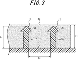
- FIG. 3 is an enlarged cross-sectional view illustrating a part of the tire of FIG. 1 in an inverted orientation in the tire radial direction to that in FIG. 1 .
- the expanded-diameter portions 12b of the pins 12 by inserting the expanded-diameter portions 12b of the pins 12 into the noise damper 13, the expanded-diameter portions 12b function as so-called stoppers in the noise damper 13 to prevent the noise damper 13 from coming out of the pins 12 inward in the tire radial direction.
- the expanded-diameter portion 12b having a diameter larger than that of the main body portion 12a functions as if it were a harpoon barb and serves as a stopper for preventing the noise damper 13 from coming out of the pin.
- the noise damper 13 is securely fixed to the pins 12. Therefore, the noise damper 13 can be stably fixed by a simple means.
- the noise damper 13 is not fixedly attached to the inner circumferential surface 2i of the tread portion 2, but rather lightly contacts the inner circumferential surface 2i. Therefore, heat dissipation from between the inner circumferential surface of the tire and the noise damper will not be hindered. Further, as the noise damper 13 is deformed while the tire is rolling, gaps are formed between the noise damper 13 and the inner circumferential surface 2i, allowing heat dissipation from the gaps. In addition, since both ends of the noise damper 13 in the tire width direction are open ends, a heat dissipation effect is also obtained from these ends.
- the noise damper 13 and the inner circumferential surface 2i of the tread portion 2 are in contact with, rather than being fixedly attached to, each other.
- the noise damper 13 may be separated from the inner circumferential surface 2i of tread portion 2.
- the pins 12 are arranged in correspondence with land portions 11a to 11c of the tread portion 2. That is, in FIG. 1 , the pins 12 are respectively arranged in correspondence with the land portions 11a, 11b, and 11c of the tread section 2, but are not arranged in the regions corresponding to circumferential grooves 10a and 10b.
- the tread portion 2 is deformed, and the deformation is apt to propagate, in particular, toward the inner circumferential surface of the tire at the locations where the grooves are formed.
- the pins 12 may be distorted or produce heat due to the propagated deformation. Therefore, by arranging the pins 12 in correspondence with the land portions 11a to 11c, such inconvenience can be avoided.
- the pins 12 are preferably arranged on and around the tire equatorial plane CL. While the tire is rolling, the tire inner circumferential surface is repeatedly deformed, and particularly in those regions on and near the tire equatorial plane CL, the tire inner circumferential surface is subject to a large strain. Therefore, by arranging the pins 12 in such regions, it is possible to prevent the noise damper 13 from falling off while the tire is rolling, and to improve the stabilization.
- the pins 12 are also preferable to arrange the pins 12 at a number density of 0.01 pcs/cm 2 or more and 0.4 pcs/cm 2 or less on the inner circumferential surface 2i of the tread portion 2. That is, on the inner circumferential surface of the tread portion 2, by setting the number density to 0.01 pcs/cm 2 or more, the noise damper 13 can be stably fixed, and by setting the number density to 0.4 pcs/cm 2 or less, it is possible to suppress a decrease in rigidity of the noise damper 13 itself.
- the shortest distance D1 between adjacent pins 12 is preferably larger than a tire radial direction length h1 (hereinafter, simply referred to as the "length") of the pins 12. With this configuration, heat buildup or damages due to contacts between the pins 12 can be prevented when pins 12 are deformed while the tire is rolling. It is also preferable that the shortest distance D1 between adjacent pins 12 be 150 % or less relative to the length h1, not only in the tire width direction, but also in the tire circumferential direction. At or below 150 %, the noise damper 13 can be stably fixed.
- the shortest distance D1 between adjacent pins 12 may be smaller than the tire radial direction length h1 of the pins 12.
- the shortest distance D1 is 80 % or less of the length h1.
- the length h1 of the pins 12 is preferably 25 % or more relative to the maximum thickness t1 of the noise damper 13. By setting hl/tl to 25 % or more, the noise damper 13 can be stably fixed.
- the length h1 of the pins 12 may be, for example, 5 mm or more and 50 mm or less. By setting the length h1 to 5 mm or more, it is possible to stably fix the noise damper 13, and by setting the length h1 to 50 mm or less, it is possible to improve the workability for mounting the tire to a rim.
- a tire radial direction length h2 of the expanded-diameter portion 12b of each pin 12 is 10 % or more and 50 % or less relative to the entire length h1 of each pin 12.
- the expanded-diameter portion 12b has a maximum diameter part having a diameter d2 of preferably 110 % or more and 200 % or less relative to the maximum diameter d1 of the main body portion 12a.
- d2/d1 is set to 110 % or more
- the expanded-diameter portion 12b can sufficiently function as a stopper for the noise damper 13, and when d2/d1 is set to 200 % or less, rigidity of the pins 12 can be ensured.
- the diameter d2 of the maximum diameter part of the expanded-diameter portion 12b may be set to 4.0 mm or more and 25.0 mm or less, and the maximum diameter d1 of the main body portion 12a to 2.0 mm or more and 20.0 mm or less.
- the maximum diameter d1 is preferably 2.0 mm or more and 5.0 mm or less.
- the value of the diameter d2 minus the maximum diameter d1 is preferably within a range of 2.0 mm to 5.0 mm. Within this range, it is possible to cause the pins 12 to function as a stopper for the noise damper 13, while maintaining rigidity.
- the shape of the pins is not limited to that illustrated in FIG. 2 , and may be, for example, the one illustrated in FIG. 4A .
- the expanded-diameter portion 12b is formed at the most distal end of the pin 12, that is, on the innermost side of the pin 12 in the tire radial direction.
- the expanded-diameter portion 12b it suffices for the expanded-diameter portion 12b to be formed on the distal end side of the pin 12, that is, further inward in the tire radial direction than the center of the tire radial direction length of the pin 12.
- the expanded-diameter portion 12b may be arranged substantially at the center in the tire radial direction of the pin 12. With this configuration, durability of the pin 12 can be increased.
- each pin 12 may have, on its proximal end side, a plane with a curvature as its outline shape near a boundary with the inner circumferential surface 2i of the tread portion. As described above, by making the shape of each pin 12 smoothly continuous with the inner circumferential surface 2i, it is possible to suppress the occurrence of cracks at the boundaries between the pins 12 and the inner circumferential surface 2i.
- the noise damper 13 may be configured to have both ends in the tire circumferential direction that are spaced apart from each other with a slight gap.
- the noise damper 13 may be an annular body in which a sheet-like sponge material is wound around more than once in the tire circumferential direction while shifting the material to the tire width direction so as not to cause overlaps of material turns.
- a plurality of sheet-like sponge materials may be intermittently arranged at intervals in the tire circumferential direction, or a plurality of sponge materials continuous over the entire circumference may be arranged in the tire width direction.
- the noise damper 13 is preferably arranged in a region w2 that extends across the tire equatorial plane CL up to 25 % or more of the tire widthwise length w1 of the tread portion 2. Within the range of 25 % or more, the effect of reducing the cavity resonance energy of the noise damper 13 can be sufficiently obtained.
- an "applicable rim” refers to a rim specified currently or in the future by the standards below in accordance with tire size.
- the “applicable rim” refers to a standard rim ("approved rim” or “recommended rim”) of applicable size specified in accordance with valid industrial standards for the region in which the tire is produced or used, such as the "JATMA Year Book” of the Japan Automobile Tire Manufacturers Association in Japan, “The European Tyre and Rim Technical Organization Standards Manual” in Europe, and "The Tire and Rim Association, Inc.
- rim in the United States of America (that is, the "rim” mentioned above includes, in addition to the current size, the size that can be included in these industry standards in the future; for example, the size described in “FUTURE DEVELOPMENTS” in the ETRTO 2013 edition).
- specified internal pressure refers to air pressure (maximum air pressure) specified in the JATMA YEAR BOOK and so on in accordance with the maximum load capability of a single wheel in the applicable size ply rating.
- air pressure maximum air pressure
- the noise damper 13 In the standard state in which the tire is mounted on an applicable rim, it is preferable that when the space formed by the inner circumferential surface of the tire 1 and the outer surface of the rim on which the tire 1 is mounted is referred to as a tire lumen In, the noise damper 13 have a volume V1 that is 0.4 % to 20 % of the total volume of the tire lumen In. By guaranteeing 0.4 % or more for the volume V1 of the noise damper 13 relative to the total volume of the tire lumen In, it is possible to obtain the effect of reducing the cavity resonance energy by a desired amount (for example, by 2 dB or more) more easily.
- the noise damper 13 more preferably accounts for 1 % or more, even more preferably 2 % or more, and particularly preferably 4 % or more of the total volume of the tire lumen In.
- increasing the volume V1 of the noise damper 13 beyond 20 % of the total volume of the tire lumen In can no longer increase the effect of reducing the cavity resonance energy. Rather, this may end up causing deterioration in the weight-balance in a state mounted on a rim.
- the volume V1 of the noise damper 13 is more preferably 16 % or less, and particularly preferably 10 % or less of the total volume of the tire lumen In.
- the above-mentioned volume ratio is not related to the number of noise dampers 13. That is, when a plurality of noise dampers 13 are used, the same effect can be obtained if the sum of the volumes of all of the noise dampers 13 satisfies the above-mentioned relationship of the volume ratio.
- the noise damper 13 is formed from a sponge material.
- the sponge material is a sponge-like porous structure, and includes, for example, a so-called sponge having open cells formed by foaming rubber or a synthetic resin.
- the sponge material includes a web-like sponge in which animal fibers, plant fibers, synthetic fibers, and the like are interlaced and integrally connected.
- the "porous structure" is not limited to a structure having open cells, and includes a structure having closed cells.
- the sponge material is easily deformed by contraction, bending, or the like. Therefore, even if the noise damper 13 made of a sponge material is in contact with the inner circumferential surface 2i of the tread, this condition does not substantially affect the deformation of the tire 1 during traveling.
- raw materials of the sponge material include synthetic resin sponge such as ether-based polyurethane sponge, ester-based polyurethane sponge, and polyethylene sponge, and rubber sponge such as chloroprene rubber sponge (CR sponge), ethylene propylene rubber sponge (EPDM sponge), and nitrile rubber sponge (NBR sponge). From the perspectives of, for example, noise damping, light weight, foaming adjustability, and durability, it is preferable to use a polyurethane- or polyethylene-based sponge including ether-based polyurethane sponge, and so on.
- synthetic resin sponge such as ether-based polyurethane sponge, ester-based polyurethane sponge, and polyethylene sponge
- rubber sponge such as chloroprene rubber sponge (CR sponge), ethylene propylene rubber sponge (EPDM sponge), and nitrile rubber sponge (NBR sponge).
- CR sponge chloroprene rubber sponge
- EPDM sponge ethylene propylene rubber sponge
- NBR sponge nitrile rubber sponge
- the material forming the noise damper 13 is not limited to the sponge material described above, and may be any material as long as it can be controlled so as to reduce the cavity resonance energy by relaxing or absorbing the energy, converting the energy to another (for example, thermal energy), and so on.
- a tire 10 of FIG. 5 comprises a resin tire framework member 14 extending toroidally between bead cores 6 embedded in a pair of bead portions 5, across the bead portions, sidewall portions 4, a shoulder portion 3, and a tread portion 2. With this configuration, it is possible to improve the formability at the time of manufacturing and reduce the weight of the tire.
- the bead cores 6 may be made of any material as long as it guarantees a desired rigidity, including, for example, metals, organic fibers, organic fibers coated with resin, and hard resin.
- the resin may include thermoplastic resin, thermoplastic elastomers (TPEs), and thermosetting resin.
- examples of the resin of the tire framework member 14 may include, similarly to the bead cores 6, thermoplastic resin, thermoplastic elastomers (TPEs), and thermosetting resin.
- thermoplastic resin thermoplastic elastomers
- thermosetting resin thermosetting resin
- thermoplastic elastomers may be used amide-based thermoplastic elastomers (TPAs), ester-based thermoplastic elastomers (TPCs), olefin-based thermoplastic elastomers (TPOs), styrene-based thermoplastic elastomers (TPSs), urethane-based thermoplastic elastomers (TPUs), thermoplastic rubber crosslinkers (TPVs), and other thermoplastic elastomers (TPZs) prescribed in the Japanese Industrial Standard (JIS) K6418.
- TPAs amide-based thermoplastic elastomers
- TPCs ester-based thermoplastic elastomers
- TPOs olefin-based thermoplastic elastomers
- TPSs styrene-based thermoplastic elastomers
- TPUs urethane-based thermoplastic elastomers
- TPUs thermoplastic rubber crosslinkers
- TPZs thermoplastic elastomers
- thermoplastic resin may be used a material having a deflection temperature under load (under a load of 0.45 MPa) prescribed in ISO75-2 or ASTM D648 of 78 °C or higher, a tensile yield strength in JIS K7113 of 10 MPa or more, a tensile elongation at break (JIS K7113) in JIS K7113 of 50 % or more, and a Vicat softening temperature (method A) in JIS K7206 of 130 °C or higher.
- the resin 4a covering the wire 4b preferably has a tensile elastic modulus (as prescribed in JIS K7113:1995) of 50 MPa or more.
- Each pin 12 may be made of any material, yet is preferably made of the same material as that of the framework member 14 and formed integrally therewith.
- thermoplastic resin thermoplastic elastomers (TPEs), or thermosetting resin may be used.
- TPEs thermoplastic elastomers
- the framework member 14 and the pins 12 have no interface in between such that a continuous member is formed, making it possible to suppress the generation of cracks at the interface between the pins 12 and the framework member 14 (the inner circumferential surface 2i).
- the framework member 14 and the pins 12 can be molded at one time, which improves productivity of the tire.
- a tire 1 illustrated in FIG. 6 is a tire having an inner reinforcing structure similar to that of the tire 1 in FIG. 1
- a tire 10 illustrated in FIG. 7 is a tire having a framework member made of resin similar to the tire 10 in FIG. 5 .
- the tires 1 of FIGS. 6 and 7 are configured in the same way as in the tire according to the first embodiment except for the mode in which the noise damper 13 is locked by the pins 12.
- the expanded-diameter portion 12b of the pins 12 are exposed to the tire radial direction inner side of the noise damper 13.
- the expanded-diameter portion 12b functions as a stopper for preventing the noise damper 13 from coming out of the pins 12 inward in the tire radial direction. That is, the expanded-diameter portion 12b supports, by its maximum diameter part, the noise damper 13 from the tire radial direction inner surface such that the noise damper 13 is fixed. In this way, the noise damper 13 can be stably fixed by a simple means.
- the noise damper 13 is not fixedly attached to any part of of the tread portion 2, such as the inner circumferential surface 2i, heat is less likely to build up between the noise damper 13 and the inner circumferential surface 2i, and furthermore, heat dissipation is accomplished from between the noise damper 13 and the inner circumferential surface 2i and from both ends in the tire width direction of the noise damper 13.
- the inner circumferential surface 2i of the tread portion 2 and the noise damper 13 are in contact with, without being fixedly attached to, each other in any of the embodiments.
- the noise damper 13 may be separated from the inner circumferential surface 2i of the tread portion 2.
- the tire radial direction length h1 of the pins 12 be more than 100 % and not more than 130 % relative to the largest thickness t1 of the noise damper 13.
- the tire radial direction length h1 of the pins 12 may be, for example, 5 mm or more and 50 mm or less.
Landscapes
- Engineering & Computer Science (AREA)
- Mechanical Engineering (AREA)
- Tires In General (AREA)
Claims (9)
- Reifen (1), der Folgendes umfasst: mindestens einen Stift (12), der von einer Innenumfangsfläche eines Laufflächenabschnitts (2) des Reifens (1) hin zu einer in Reifenradialrichtung inneren Seite vorspringt, und einen Geräuschdämpfer (13), der durch den mindestens einen Stift (12) gehalten wird,
wobeider mindestens eine Stift (12), an seinem distalen Ende, einen Abschnitt mit erweitertem Durchmesser (12a) aufweist,durch den der Geräuschdämpfer (13) derart arretiert wird, dass der Geräuschdämpfer (13) an dem Stift (12) fixiert ist, dadurch gekennzeichnet, dassder mindestens eine Stift (12) in Übereinstimmung mit einem Landabschnitt (11a, 11b, 11c) des Laufflächenabschnitts (2) des Reifens (1) angeordnet ist, und dadurch, dasskeine Stifte (12) in den Bereichen angeordnet sind, die umlaufenden Rillen (10a, 10b) entsprechen, die an dem Laufflächenabschnitt (2) des Reifens (1) bereitgestellt werden. - Reifen (1) nach Anspruch 1, wobei der Abschnitt mit erweitertem Durchmesser (12a) innerhalb des Geräuschdämpfers (13) angeordnet ist.
- Reifen (1) nach Anspruch 1, wobei der Abschnitt mit erweitertem Durchmesser (12a) zu einer in Reifenradialrichtung inneren Seite des Geräuschdämpfers (13) freigelegt ist.
- Reifen (1) nach einem der Ansprüche 1 bis 3, der ein Gerüstelement (14) umfasst, das aus Harz hergestellt ist.
- Reifen (1) nach Anspruch 4, wobei das Gerüstelement (14), das aus Harz hergestellt ist, und der mindestens eine Stift (12) aus dem gleichen Material hergestellt sind und integral geformt sind.
- Reifen (1) nach einem der Ansprüche 1 bis 5, wobei der mindestens eine Stift mit einer Anzahldichte von 0,01 Stck./cm2 bis 0,4 Stck./cm2 auf der Innenumfangsfläche des Laufflächenabschnitts angeordnet ist.
- Reifen (1) nach einem der Ansprüche 1 bis 6, wobei der mindestens eine Stift (12) eine Vielzahl von Stiften (12) umfasst und ein kürzester Abstand zwischen den Stiften (12) größer ist als eine Länge der Stifte (12) in Reifenradialrichtung.
- Reifen (1) nach einem der Ansprüche 1 bis 7, wobei der Abschnitt mit erweitertem Durchmesser (12a) ein konischer Festkörper ist, der einen Scheitel in der Reifenradialrichtung nach innen aufweist.
- Reifen (1) nach einem der Ansprüche 1 bis 8, wobei der mindestens eine Stift (12), auf seiner proximalen Endseite, eine Ebene mit einer Krümmung als seine Umrissform nahe einer Grenze mit der Innenumfangsfläche des Laufflächenabschnitts (2) aufweist.
Priority Applications (1)
| Application Number | Priority Date | Filing Date | Title |
|---|---|---|---|
| EP21212644.5A EP3984767B1 (de) | 2017-11-13 | 2018-09-26 | Reifen |
Applications Claiming Priority (2)
| Application Number | Priority Date | Filing Date | Title |
|---|---|---|---|
| JP2017218604A JP2019089409A (ja) | 2017-11-13 | 2017-11-13 | タイヤ |
| PCT/JP2018/035751 WO2019093006A1 (ja) | 2017-11-13 | 2018-09-26 | タイヤ |
Related Child Applications (2)
| Application Number | Title | Priority Date | Filing Date |
|---|---|---|---|
| EP21212644.5A Division EP3984767B1 (de) | 2017-11-13 | 2018-09-26 | Reifen |
| EP21212644.5A Division-Into EP3984767B1 (de) | 2017-11-13 | 2018-09-26 | Reifen |
Publications (3)
| Publication Number | Publication Date |
|---|---|
| EP3711976A1 EP3711976A1 (de) | 2020-09-23 |
| EP3711976A4 EP3711976A4 (de) | 2021-07-28 |
| EP3711976B1 true EP3711976B1 (de) | 2023-03-15 |
Family
ID=66438102
Family Applications (2)
| Application Number | Title | Priority Date | Filing Date |
|---|---|---|---|
| EP18876280.1A Active EP3711976B1 (de) | 2017-11-13 | 2018-09-26 | Reifen |
| EP21212644.5A Active EP3984767B1 (de) | 2017-11-13 | 2018-09-26 | Reifen |
Family Applications After (1)
| Application Number | Title | Priority Date | Filing Date |
|---|---|---|---|
| EP21212644.5A Active EP3984767B1 (de) | 2017-11-13 | 2018-09-26 | Reifen |
Country Status (5)
| Country | Link |
|---|---|
| US (1) | US20210070114A1 (de) |
| EP (2) | EP3711976B1 (de) |
| JP (1) | JP2019089409A (de) |
| CN (1) | CN111344159B (de) |
| WO (1) | WO2019093006A1 (de) |
Families Citing this family (5)
| Publication number | Priority date | Publication date | Assignee | Title |
|---|---|---|---|---|
| CN113757057A (zh) * | 2021-08-02 | 2021-12-07 | 上海寅生科技有限公司 | 一种拉力无级调节配重发电机构和具有其的健身器 |
| JP7786174B2 (ja) * | 2021-12-07 | 2025-12-16 | 住友ゴム工業株式会社 | 空気入りタイヤ |
| JP2025005868A (ja) * | 2023-06-28 | 2025-01-17 | 住友ゴム工業株式会社 | 空気入りタイヤ、空気入りタイヤのパンク修理方法、及び、車両 |
| JP2025005867A (ja) * | 2023-06-28 | 2025-01-17 | 住友ゴム工業株式会社 | 空気入りタイヤ、空気入りタイヤのパンク修理方法、及び、車両 |
| JP2025005866A (ja) * | 2023-06-28 | 2025-01-17 | 住友ゴム工業株式会社 | 空気入りタイヤ、空気入りタイヤのパンク修理方法、及び、車両 |
Family Cites Families (21)
| Publication number | Priority date | Publication date | Assignee | Title |
|---|---|---|---|---|
| GB735882A (en) * | 1951-10-24 | 1955-08-31 | Firestone Tire & Rubber Co | Improvements in pneumatic tire |
| JPH04318639A (ja) | 1991-04-17 | 1992-11-10 | Mitsubishi Electric Corp | ワンチップマイクロコンピュータのメモリマッピング方式 |
| JP3934621B2 (ja) * | 2004-03-16 | 2007-06-20 | 住友ゴム工業株式会社 | 空気入りタイヤとリムとの組立体 |
| JP3916625B2 (ja) * | 2004-08-05 | 2007-05-16 | 横浜ゴム株式会社 | 空気入りタイヤ |
| JP4769078B2 (ja) * | 2005-12-12 | 2011-09-07 | 住友ゴム工業株式会社 | 空気入りタイヤ |
| JP4899600B2 (ja) * | 2006-04-11 | 2012-03-21 | 横浜ゴム株式会社 | 空気入りタイヤ |
| JP4220542B2 (ja) * | 2006-10-25 | 2009-02-04 | 横浜ゴム株式会社 | 空気入りタイヤ |
| FR2908068B1 (fr) * | 2006-11-02 | 2009-01-16 | Michelin Soc Tech | Procede de moulage d'un pneumatique ayant des performances en bruit ameliorees. |
| JP4760760B2 (ja) * | 2007-04-06 | 2011-08-31 | 横浜ゴム株式会社 | 空気入りタイヤ |
| JP4532520B2 (ja) * | 2007-04-25 | 2010-08-25 | 横浜ゴム株式会社 | 面ファスナー付き空気入りタイヤ及びその製造方法 |
| DE102007060866A1 (de) * | 2007-12-18 | 2009-06-25 | GM Global Technology Operations, Inc., Detroit | Luftreifen und Anordnung zur Verminderung eines Reifengeräuschs |
| JP4989449B2 (ja) * | 2007-12-25 | 2012-08-01 | 横浜ゴム株式会社 | 空気入りタイヤの製造方法及び空気入りタイヤ |
| JP5267288B2 (ja) * | 2008-05-09 | 2013-08-21 | 横浜ゴム株式会社 | タイヤ騒音低減装置 |
| JP4862918B2 (ja) * | 2009-06-05 | 2012-01-25 | 横浜ゴム株式会社 | 空気入りタイヤ |
| JP5863308B2 (ja) * | 2010-11-25 | 2016-02-16 | 横浜ゴム株式会社 | 空気入りタイヤの製造方法 |
| JP5760678B2 (ja) * | 2011-05-18 | 2015-08-12 | 横浜ゴム株式会社 | 空気入りタイヤ及びその製造方法 |
| JP2012240603A (ja) * | 2011-05-23 | 2012-12-10 | Yokohama Rubber Co Ltd:The | 空気入りタイヤ |
| KR101345647B1 (ko) * | 2011-12-16 | 2013-12-31 | 한국타이어 주식회사 | 소음 감쇠 블럭을 구비하는 공기입 타이어 |
| JP6002562B2 (ja) * | 2012-12-05 | 2016-10-05 | 横浜ゴム株式会社 | 面ファスナー付き空気入りタイヤ及びその製造方法 |
| US10632790B2 (en) | 2014-09-12 | 2020-04-28 | Bridgestone Corporation | Pneumatic tire |
| JP6235990B2 (ja) * | 2014-10-17 | 2017-11-22 | 住友ゴム工業株式会社 | シーラントタイヤ |
-
2017
- 2017-11-13 JP JP2017218604A patent/JP2019089409A/ja active Pending
-
2018
- 2018-09-26 WO PCT/JP2018/035751 patent/WO2019093006A1/ja not_active Ceased
- 2018-09-26 CN CN201880072626.XA patent/CN111344159B/zh active Active
- 2018-09-26 EP EP18876280.1A patent/EP3711976B1/de active Active
- 2018-09-26 US US16/763,228 patent/US20210070114A1/en not_active Abandoned
- 2018-09-26 EP EP21212644.5A patent/EP3984767B1/de active Active
Also Published As
| Publication number | Publication date |
|---|---|
| WO2019093006A1 (ja) | 2019-05-16 |
| CN111344159A (zh) | 2020-06-26 |
| US20210070114A1 (en) | 2021-03-11 |
| EP3984767A1 (de) | 2022-04-20 |
| EP3711976A1 (de) | 2020-09-23 |
| JP2019089409A (ja) | 2019-06-13 |
| EP3711976A4 (de) | 2021-07-28 |
| EP3984767B1 (de) | 2025-08-06 |
| CN111344159B (zh) | 2022-06-07 |
Similar Documents
| Publication | Publication Date | Title |
|---|---|---|
| EP3711976B1 (de) | Reifen | |
| JP6754168B2 (ja) | タイヤ | |
| US11890899B2 (en) | Pneumatic tire, pneumatic tire assembly, and power supply system | |
| CN110770043A (zh) | 充气轮胎 | |
| EP3711975B1 (de) | Reifen | |
| US20210070103A1 (en) | Non-pneumatic tire | |
| JP2006182280A (ja) | 空気入りタイヤとリムとの組立体 | |
| US20200114705A1 (en) | Pneumatic tire with noise-absorbing member and tire-and-rim assembly | |
| JP2022164929A (ja) | 乗用車用空気入りラジアルタイヤ | |
| CN111284279A (zh) | 充气轮胎 | |
| EP3805014B1 (de) | Reifen | |
| JP6814699B2 (ja) | 空気入りラジアルタイヤ | |
| JP2003136921A (ja) | 空気入りタイヤおよびタイヤとリムとの組み立て体 | |
| JP5054955B2 (ja) | 航空機ラジアルタイヤ | |
| JP2007008250A (ja) | 空気入りタイヤ | |
| EP3643523A1 (de) | Luftreifen | |
| WO2015005450A1 (ja) | 空気入りタイヤ | |
| CN110831783A (zh) | 充气轮胎 | |
| EP3967524B1 (de) | Luftreifen | |
| JP6786447B2 (ja) | 空気入りタイヤ | |
| JP2008049923A (ja) | 空気入りタイヤ | |
| US20190160875A1 (en) | Pneumatic tire | |
| JP2021024306A (ja) | 空気入りタイヤ | |
| CN110770042A (zh) | 充气轮胎 | |
| JP2005001424A (ja) | タイヤ用のサポートリング及びそれを用いたタイヤ組立体 |
Legal Events
| Date | Code | Title | Description |
|---|---|---|---|
| STAA | Information on the status of an ep patent application or granted ep patent |
Free format text: STATUS: THE INTERNATIONAL PUBLICATION HAS BEEN MADE |
|
| PUAI | Public reference made under article 153(3) epc to a published international application that has entered the european phase |
Free format text: ORIGINAL CODE: 0009012 |
|
| STAA | Information on the status of an ep patent application or granted ep patent |
Free format text: STATUS: REQUEST FOR EXAMINATION WAS MADE |
|
| 17P | Request for examination filed |
Effective date: 20200512 |
|
| AK | Designated contracting states |
Kind code of ref document: A1 Designated state(s): AL AT BE BG CH CY CZ DE DK EE ES FI FR GB GR HR HU IE IS IT LI LT LU LV MC MK MT NL NO PL PT RO RS SE SI SK SM TR |
|
| AX | Request for extension of the european patent |
Extension state: BA ME |
|
| DAV | Request for validation of the european patent (deleted) | ||
| DAX | Request for extension of the european patent (deleted) | ||
| A4 | Supplementary search report drawn up and despatched |
Effective date: 20210624 |
|
| RIC1 | Information provided on ipc code assigned before grant |
Ipc: B60C 5/00 20060101AFI20210618BHEP Ipc: B60C 19/00 20060101ALI20210618BHEP |
|
| GRAP | Despatch of communication of intention to grant a patent |
Free format text: ORIGINAL CODE: EPIDOSNIGR1 |
|
| STAA | Information on the status of an ep patent application or granted ep patent |
Free format text: STATUS: GRANT OF PATENT IS INTENDED |
|
| INTG | Intention to grant announced |
Effective date: 20221114 |
|
| GRAS | Grant fee paid |
Free format text: ORIGINAL CODE: EPIDOSNIGR3 |
|
| GRAA | (expected) grant |
Free format text: ORIGINAL CODE: 0009210 |
|
| STAA | Information on the status of an ep patent application or granted ep patent |
Free format text: STATUS: THE PATENT HAS BEEN GRANTED |
|
| AK | Designated contracting states |
Kind code of ref document: B1 Designated state(s): AL AT BE BG CH CY CZ DE DK EE ES FI FR GB GR HR HU IE IS IT LI LT LU LV MC MK MT NL NO PL PT RO RS SE SI SK SM TR |
|
| REG | Reference to a national code |
Ref country code: CH Ref legal event code: EP Ref country code: GB Ref legal event code: FG4D |
|
| REG | Reference to a national code |
Ref country code: DE Ref legal event code: R096 Ref document number: 602018047342 Country of ref document: DE |
|
| REG | Reference to a national code |
Ref country code: IE Ref legal event code: FG4D |
|
| REG | Reference to a national code |
Ref country code: AT Ref legal event code: REF Ref document number: 1553789 Country of ref document: AT Kind code of ref document: T Effective date: 20230415 |
|
| P01 | Opt-out of the competence of the unified patent court (upc) registered |
Effective date: 20230526 |
|
| REG | Reference to a national code |
Ref country code: LT Ref legal event code: MG9D |
|
| REG | Reference to a national code |
Ref country code: NL Ref legal event code: MP Effective date: 20230315 |
|
| PG25 | Lapsed in a contracting state [announced via postgrant information from national office to epo] |
Ref country code: RS Free format text: LAPSE BECAUSE OF FAILURE TO SUBMIT A TRANSLATION OF THE DESCRIPTION OR TO PAY THE FEE WITHIN THE PRESCRIBED TIME-LIMIT Effective date: 20230315 Ref country code: NO Free format text: LAPSE BECAUSE OF FAILURE TO SUBMIT A TRANSLATION OF THE DESCRIPTION OR TO PAY THE FEE WITHIN THE PRESCRIBED TIME-LIMIT Effective date: 20230615 Ref country code: LV Free format text: LAPSE BECAUSE OF FAILURE TO SUBMIT A TRANSLATION OF THE DESCRIPTION OR TO PAY THE FEE WITHIN THE PRESCRIBED TIME-LIMIT Effective date: 20230315 Ref country code: LT Free format text: LAPSE BECAUSE OF FAILURE TO SUBMIT A TRANSLATION OF THE DESCRIPTION OR TO PAY THE FEE WITHIN THE PRESCRIBED TIME-LIMIT Effective date: 20230315 Ref country code: HR Free format text: LAPSE BECAUSE OF FAILURE TO SUBMIT A TRANSLATION OF THE DESCRIPTION OR TO PAY THE FEE WITHIN THE PRESCRIBED TIME-LIMIT Effective date: 20230315 |
|
| REG | Reference to a national code |
Ref country code: AT Ref legal event code: MK05 Ref document number: 1553789 Country of ref document: AT Kind code of ref document: T Effective date: 20230315 |
|
| PG25 | Lapsed in a contracting state [announced via postgrant information from national office to epo] |
Ref country code: SE Free format text: LAPSE BECAUSE OF FAILURE TO SUBMIT A TRANSLATION OF THE DESCRIPTION OR TO PAY THE FEE WITHIN THE PRESCRIBED TIME-LIMIT Effective date: 20230315 Ref country code: NL Free format text: LAPSE BECAUSE OF FAILURE TO SUBMIT A TRANSLATION OF THE DESCRIPTION OR TO PAY THE FEE WITHIN THE PRESCRIBED TIME-LIMIT Effective date: 20230315 Ref country code: GR Free format text: LAPSE BECAUSE OF FAILURE TO SUBMIT A TRANSLATION OF THE DESCRIPTION OR TO PAY THE FEE WITHIN THE PRESCRIBED TIME-LIMIT Effective date: 20230616 Ref country code: FI Free format text: LAPSE BECAUSE OF FAILURE TO SUBMIT A TRANSLATION OF THE DESCRIPTION OR TO PAY THE FEE WITHIN THE PRESCRIBED TIME-LIMIT Effective date: 20230315 |
|
| PG25 | Lapsed in a contracting state [announced via postgrant information from national office to epo] |
Ref country code: SM Free format text: LAPSE BECAUSE OF FAILURE TO SUBMIT A TRANSLATION OF THE DESCRIPTION OR TO PAY THE FEE WITHIN THE PRESCRIBED TIME-LIMIT Effective date: 20230315 Ref country code: RO Free format text: LAPSE BECAUSE OF FAILURE TO SUBMIT A TRANSLATION OF THE DESCRIPTION OR TO PAY THE FEE WITHIN THE PRESCRIBED TIME-LIMIT Effective date: 20230315 Ref country code: PT Free format text: LAPSE BECAUSE OF FAILURE TO SUBMIT A TRANSLATION OF THE DESCRIPTION OR TO PAY THE FEE WITHIN THE PRESCRIBED TIME-LIMIT Effective date: 20230717 Ref country code: ES Free format text: LAPSE BECAUSE OF FAILURE TO SUBMIT A TRANSLATION OF THE DESCRIPTION OR TO PAY THE FEE WITHIN THE PRESCRIBED TIME-LIMIT Effective date: 20230315 Ref country code: EE Free format text: LAPSE BECAUSE OF FAILURE TO SUBMIT A TRANSLATION OF THE DESCRIPTION OR TO PAY THE FEE WITHIN THE PRESCRIBED TIME-LIMIT Effective date: 20230315 Ref country code: CZ Free format text: LAPSE BECAUSE OF FAILURE TO SUBMIT A TRANSLATION OF THE DESCRIPTION OR TO PAY THE FEE WITHIN THE PRESCRIBED TIME-LIMIT Effective date: 20230315 Ref country code: AT Free format text: LAPSE BECAUSE OF FAILURE TO SUBMIT A TRANSLATION OF THE DESCRIPTION OR TO PAY THE FEE WITHIN THE PRESCRIBED TIME-LIMIT Effective date: 20230315 |
|
| PG25 | Lapsed in a contracting state [announced via postgrant information from national office to epo] |
Ref country code: SK Free format text: LAPSE BECAUSE OF FAILURE TO SUBMIT A TRANSLATION OF THE DESCRIPTION OR TO PAY THE FEE WITHIN THE PRESCRIBED TIME-LIMIT Effective date: 20230315 Ref country code: PL Free format text: LAPSE BECAUSE OF FAILURE TO SUBMIT A TRANSLATION OF THE DESCRIPTION OR TO PAY THE FEE WITHIN THE PRESCRIBED TIME-LIMIT Effective date: 20230315 Ref country code: IS Free format text: LAPSE BECAUSE OF FAILURE TO SUBMIT A TRANSLATION OF THE DESCRIPTION OR TO PAY THE FEE WITHIN THE PRESCRIBED TIME-LIMIT Effective date: 20230715 |
|
| REG | Reference to a national code |
Ref country code: DE Ref legal event code: R097 Ref document number: 602018047342 Country of ref document: DE |
|
| PLBE | No opposition filed within time limit |
Free format text: ORIGINAL CODE: 0009261 |
|
| STAA | Information on the status of an ep patent application or granted ep patent |
Free format text: STATUS: NO OPPOSITION FILED WITHIN TIME LIMIT |
|
| PG25 | Lapsed in a contracting state [announced via postgrant information from national office to epo] |
Ref country code: SI Free format text: LAPSE BECAUSE OF FAILURE TO SUBMIT A TRANSLATION OF THE DESCRIPTION OR TO PAY THE FEE WITHIN THE PRESCRIBED TIME-LIMIT Effective date: 20230315 Ref country code: DK Free format text: LAPSE BECAUSE OF FAILURE TO SUBMIT A TRANSLATION OF THE DESCRIPTION OR TO PAY THE FEE WITHIN THE PRESCRIBED TIME-LIMIT Effective date: 20230315 |
|
| 26N | No opposition filed |
Effective date: 20231218 |
|
| REG | Reference to a national code |
Ref country code: CH Ref legal event code: PL |
|
| PG25 | Lapsed in a contracting state [announced via postgrant information from national office to epo] |
Ref country code: LU Free format text: LAPSE BECAUSE OF NON-PAYMENT OF DUE FEES Effective date: 20230926 |
|
| REG | Reference to a national code |
Ref country code: BE Ref legal event code: MM Effective date: 20230930 |
|
| GBPC | Gb: european patent ceased through non-payment of renewal fee |
Effective date: 20230926 |
|
| PG25 | Lapsed in a contracting state [announced via postgrant information from national office to epo] |
Ref country code: LU Free format text: LAPSE BECAUSE OF NON-PAYMENT OF DUE FEES Effective date: 20230926 Ref country code: IT Free format text: LAPSE BECAUSE OF FAILURE TO SUBMIT A TRANSLATION OF THE DESCRIPTION OR TO PAY THE FEE WITHIN THE PRESCRIBED TIME-LIMIT Effective date: 20230315 Ref country code: MC Free format text: LAPSE BECAUSE OF FAILURE TO SUBMIT A TRANSLATION OF THE DESCRIPTION OR TO PAY THE FEE WITHIN THE PRESCRIBED TIME-LIMIT Effective date: 20230315 |
|
| REG | Reference to a national code |
Ref country code: IE Ref legal event code: MM4A |
|
| PG25 | Lapsed in a contracting state [announced via postgrant information from national office to epo] |
Ref country code: IE Free format text: LAPSE BECAUSE OF NON-PAYMENT OF DUE FEES Effective date: 20230926 |
|
| PG25 | Lapsed in a contracting state [announced via postgrant information from national office to epo] |
Ref country code: GB Free format text: LAPSE BECAUSE OF NON-PAYMENT OF DUE FEES Effective date: 20230926 |
|
| PG25 | Lapsed in a contracting state [announced via postgrant information from national office to epo] |
Ref country code: CH Free format text: LAPSE BECAUSE OF NON-PAYMENT OF DUE FEES Effective date: 20230930 |
|
| PG25 | Lapsed in a contracting state [announced via postgrant information from national office to epo] |
Ref country code: IE Free format text: LAPSE BECAUSE OF NON-PAYMENT OF DUE FEES Effective date: 20230926 Ref country code: GB Free format text: LAPSE BECAUSE OF NON-PAYMENT OF DUE FEES Effective date: 20230926 Ref country code: CH Free format text: LAPSE BECAUSE OF NON-PAYMENT OF DUE FEES Effective date: 20230930 |
|
| PG25 | Lapsed in a contracting state [announced via postgrant information from national office to epo] |
Ref country code: BE Free format text: LAPSE BECAUSE OF NON-PAYMENT OF DUE FEES Effective date: 20230930 |
|
| PG25 | Lapsed in a contracting state [announced via postgrant information from national office to epo] |
Ref country code: BG Free format text: LAPSE BECAUSE OF FAILURE TO SUBMIT A TRANSLATION OF THE DESCRIPTION OR TO PAY THE FEE WITHIN THE PRESCRIBED TIME-LIMIT Effective date: 20230315 |
|
| PG25 | Lapsed in a contracting state [announced via postgrant information from national office to epo] |
Ref country code: BG Free format text: LAPSE BECAUSE OF FAILURE TO SUBMIT A TRANSLATION OF THE DESCRIPTION OR TO PAY THE FEE WITHIN THE PRESCRIBED TIME-LIMIT Effective date: 20230315 |
|
| PG25 | Lapsed in a contracting state [announced via postgrant information from national office to epo] |
Ref country code: CY Free format text: LAPSE BECAUSE OF FAILURE TO SUBMIT A TRANSLATION OF THE DESCRIPTION OR TO PAY THE FEE WITHIN THE PRESCRIBED TIME-LIMIT; INVALID AB INITIO Effective date: 20180926 |
|
| PG25 | Lapsed in a contracting state [announced via postgrant information from national office to epo] |
Ref country code: HU Free format text: LAPSE BECAUSE OF FAILURE TO SUBMIT A TRANSLATION OF THE DESCRIPTION OR TO PAY THE FEE WITHIN THE PRESCRIBED TIME-LIMIT; INVALID AB INITIO Effective date: 20180926 |
|
| PGFP | Annual fee paid to national office [announced via postgrant information from national office to epo] |
Ref country code: DE Payment date: 20250919 Year of fee payment: 8 |
|
| PGFP | Annual fee paid to national office [announced via postgrant information from national office to epo] |
Ref country code: FR Payment date: 20250922 Year of fee payment: 8 |
|
| PG25 | Lapsed in a contracting state [announced via postgrant information from national office to epo] |
Ref country code: TR Free format text: LAPSE BECAUSE OF FAILURE TO SUBMIT A TRANSLATION OF THE DESCRIPTION OR TO PAY THE FEE WITHIN THE PRESCRIBED TIME-LIMIT Effective date: 20230315 |