EP3711477B1 - Hydrokulturvorrichtung und hydrokulturverfahren - Google Patents
Hydrokulturvorrichtung und hydrokulturverfahren Download PDFInfo
- Publication number
- EP3711477B1 EP3711477B1 EP18876180.3A EP18876180A EP3711477B1 EP 3711477 B1 EP3711477 B1 EP 3711477B1 EP 18876180 A EP18876180 A EP 18876180A EP 3711477 B1 EP3711477 B1 EP 3711477B1
- Authority
- EP
- European Patent Office
- Prior art keywords
- nutrient solution
- plants
- taproots
- reservoir container
- solution reservoir
- Prior art date
- Legal status (The legal status is an assumption and is not a legal conclusion. Google has not performed a legal analysis and makes no representation as to the accuracy of the status listed.)
- Active
Links
Images








Classifications
-
- A—HUMAN NECESSITIES
- A01—AGRICULTURE; FORESTRY; ANIMAL HUSBANDRY; HUNTING; TRAPPING; FISHING
- A01G—HORTICULTURE; CULTIVATION OF VEGETABLES, FLOWERS, RICE, FRUIT, VINES, HOPS OR SEAWEED; FORESTRY; WATERING
- A01G31/00—Soilless cultivation, e.g. hydroponics
- A01G31/02—Special apparatus therefor
-
- A—HUMAN NECESSITIES
- A01—AGRICULTURE; FORESTRY; ANIMAL HUSBANDRY; HUNTING; TRAPPING; FISHING
- A01G—HORTICULTURE; CULTIVATION OF VEGETABLES, FLOWERS, RICE, FRUIT, VINES, HOPS OR SEAWEED; FORESTRY; WATERING
- A01G31/00—Soilless cultivation, e.g. hydroponics
- A01G31/02—Special apparatus therefor
- A01G31/06—Hydroponic culture on racks or in stacked containers
-
- A—HUMAN NECESSITIES
- A01—AGRICULTURE; FORESTRY; ANIMAL HUSBANDRY; HUNTING; TRAPPING; FISHING
- A01G—HORTICULTURE; CULTIVATION OF VEGETABLES, FLOWERS, RICE, FRUIT, VINES, HOPS OR SEAWEED; FORESTRY; WATERING
- A01G31/00—Soilless cultivation, e.g. hydroponics
- A01G31/02—Special apparatus therefor
- A01G31/065—Special apparatus therefor with means for recycling the nutritive solution
-
- Y—GENERAL TAGGING OF NEW TECHNOLOGICAL DEVELOPMENTS; GENERAL TAGGING OF CROSS-SECTIONAL TECHNOLOGIES SPANNING OVER SEVERAL SECTIONS OF THE IPC; TECHNICAL SUBJECTS COVERED BY FORMER USPC CROSS-REFERENCE ART COLLECTIONS [XRACs] AND DIGESTS
- Y02—TECHNOLOGIES OR APPLICATIONS FOR MITIGATION OR ADAPTATION AGAINST CLIMATE CHANGE
- Y02P—CLIMATE CHANGE MITIGATION TECHNOLOGIES IN THE PRODUCTION OR PROCESSING OF GOODS
- Y02P60/00—Technologies relating to agriculture, livestock or agroalimentary industries
- Y02P60/20—Reduction of greenhouse gas [GHG] emissions in agriculture, e.g. CO2
- Y02P60/21—Dinitrogen oxide [N2O], e.g. using aquaponics, hydroponics or efficiency measures
Definitions
- the present invention relates to a hydroponics device and a hydroponics method.
- Such cultivation systems include, as main elements, a delivery and supply channel, a discharge channel and a plurality of cultivation containers.
- the delivery and supply channel supplies a nutrient solution from a main mixing tank and a treated nutrient solution using pipes to the plurality of cultivation containers.
- the discharge channel recovers waste liquid from the cultivation containers for supply to a waste liquid treatment device.
- the plurality of cultivation containers each hold the nutrient solution supplied through the delivery and supply channel, and each independently grow plants which are a predetermined number of different strains of the same species.
- the plurality of cultivation containers each have a body a part of which is provided with an extensible bellows throughout the circumference to serve as a liquid level control means that controls a liquid level according the growth of the plants.
- the lower part of each cultivation container can be extended downward according to the growth of the plants, so that a predetermined quantity of nutrient solution can be held in the cultivation container.
- Such cultivation containers are each controlled in height while the growth of the plants is observed in one common container.
- root vegetables can be grown while the roots are permitted to dilate in one common container.
- the cultivation systems as disclosed in PTL 1 involve tasks of extending the lower parts of the cultivation containers downward according to the growth of the plants and use of a liquid level control means. Therefore, it has been difficult to install multistage cultivation shelves in such cultivation systems. For this reason, it has not been easy to increase productivity per unit area in these cultivation systems.
- the height of each cultivation container is controlled while the growth of the plants is observed in one common container, so that root vegetables can be grown while the roots are permitted to dilate therein. Therefore, when a plurality of such cultivation containers are used, a large quantity of nutrient solution has been required.
- the present invention aims to provide a hydroponics device and a hydroponics method which can increase productivity per unit area in hydroponics and decrease the amount of a required nutrient solution to reduce cost involved in running the device.
- a nutrient solution reservoir container into which a nutrient solution in a nutrient solution storage is supplied, and a cover that supports a plurality of plants to be cultivated, the cover being fixed spaced from a liquid surface of the nutrient solution in the nutrient solution reservoir container, with a predetermined distance being ensured between the cover and the liquid surface.
- the plants supported by the cover respectively have taproots which are longer than the lengths of shoots of the plants, the taproots having respective tips only immersed in the nutrient solution in the nutrient solution reservoir container.
- Fig. 2 is a schematic diagram illustrating a first example of a hydroponics device according to the present invention.
- solar plant factories or closed plant factories using artificial light are equipped with multistage cultivation shelves (not shown) on which a plurality of hydroponics devices are arranged.
- Fig. 2 shows one representative hydroponics device.
- the hydroponics device includes, for example, a tank 12, a pump 12P, a nutrient solution reservoir container (also termed pan hereinafter) 10B, a cover 14 and a cover support 10C.
- the tank 12 stores a nutrient solution LQ1 that is a liquid fertilizer whose concentration has been adjusted to a predetermined level.
- the pump 12P is disposed in the tank 12 and supplies the nutrient solution LQ1 in the tank 12 to a supply path Du2 described later.
- the pan 10B forms a lower part of a cultivation planter, which will be described later, and holds a predetermined quantity of the nutrient solution LQ1.
- the cover 14 forms an upper part of the cultivation planter 10.
- the cover support 10C supports the cover 14 from beneath the cover 14 and is detachably connected to the pan 10B.
- Fig. 2 shows plants 28 P1 , 28 P2 , 28 P3 , 28 P4 and 28 P5 as representative of a plurality of plants 28 P1 to 28 Pn .
- the plants 28 P1 , 28 P2 , 28 P3 , 28 P4 , 28 P5 may be root vegetables which are a predetermined number of strains such as of carrots, ginseng (Korean ginseng), licorice, coptis, angelica acutiloba (herbal medicines), yam, turnips, burdock and Japanese radishes.
- the cover 14 supports the plants 28 P1 , 28 P2 , 28 P3 , 28 P4 , 28 P5 ... and 28 Pn , which are a predetermined number of different strains of the same species, via respective plant fixing stoppers 14a serving as pads, which will be described later, so that tips (portions respectively including rootcaps and apical meristems) 28b of respective taproots 28a of the plants are immersed in the nutrient solution LQ1 in the pan 10B.
- the plant fixing stoppers 14a are arranged at positions corresponding to openings of the cover 14.
- the plurality of openings of the cover 14 are formed in a matrix at predetermined intervals.
- the plant fixing stoppers 14a each include, on the inside thereof, a seal holder in which a plurality of sealing members are held being overlaid with each other.
- the plant fixing stoppers 14a may be members, such as urethane sponge mats, having flexibility and stretchability.
- shoots 28c of the plants 28 P1 , 28 P2 , 28 P3 , 28 P4 and 28 P5 can be supported in the cover 14 by the respective plant fixing stoppers 14a.
- the cover support 10C has a growth space 10A on the inside thereof for holding dilating portions 48c in the roots of grown plants 48 P1 , 48 P2 , 48 P3 , 48 P4 and 48 P5 .
- the growth space (air layer) 10A has a height HA exceeding the length in the elongation growth direction of the dilating portions 48c in the roots of the grown plants 48 P1 , 48 P2 , 48 P3 , 48 P4 and 48 P5 at the time of harvest.
- the height HA is set to 50 cm or more.
- the height HA may be set to a predetermined height of less than 50 cm depending on the lengths in the elongation growth direction of the dilating portions in the roots of grown plants of different species at the time of harvest.
- the height HA may be set to a value in the range of about 20 cm or more and 30 cm or less.
- the height HA does not necessarily have to be fixed to a predetermined value during growth of the plants. For example, there would be no problem as long as the cultivation planter 10 has a mechanism enabling stepwise or stepless adjustment in height of the space, where the liquid level of the nutrient solution LQ1 is sustained and the bases of the seedlings are held, according to the growth of the taproots of long roots.
- Green algae may develop in a tank or in a moist place around the tank. If algae have developed in the nutrient solution, removal of the algae may not be easy, and nutrients in the solution may be consumed by the algae.
- a nutrient solution that has developed algae may be a source of various bacteria.
- the air layer 10Abetween the cover 14 and the nutrient solution reservoir container 10B may be enclosed by a sheet, e.g., a transparent or translucent sheet, or a light-shielding sheet or the like. Since water and nutrients reside in the nutrient solution, algae may not develop if the sheet can prevent entry of algae from outside or can shield against light.
- the sheet enclosing the air layer may ensure a stable environment of exerting an effect of reducing variation in temperature or humidity, resultantly ensuring a stable cultivation environment.
- the nutrient solution LQ1 is stored with a predetermined liquid level sustained.
- the pump 12P having a discharge port that is connected to an end of the supply path Du2.
- the pump 12P is controlled by a control unit, not shown.
- the pump 12P is activated, the nutrient solution LQ1 in the tank 12 is supplied to a reservoir in the pan 10B, which will be described later, through the supply path Du2.
- the pump 12P is activated, the nutrient solution LQ1 in the tank 12 is circulated via the supply path Du2 and a return discharge path Du1.
- the pan 10B has a reservoir in the interior for holding a predetermined quantity of the nutrient solution LQ1 supplied from the tank 12 via the supply path Du2.
- the reservoir has a top that is open to the growth space 10A mentioned above.
- the other end of the supply path Du2 is open to the liquid surface of the nutrient solution LQ1 in the reservoir.
- an open end of a discharge pipe 16 protrudes by a predetermined length.
- the open end of the discharge pipe 16 serving as a liquid level control means has a protrusion length which is set, for example, to about 3 cm.
- the liquid level of the nutrient solution LQ1 rises, the nutrient solution LQ1 is discharged to the return discharge path Du1, which is ensured to communicate with the tank 12, via the discharge pipe 16. Therefore, the liquid level of the nutrient solution LQ1 is controlled to a predetermined liquid level LH corresponding to the predetermined length of the taproots 28a of the plants.
- the plants 28 P1 , 28 P2 , 28 P3 , 28 P4 , 28 P5 ... and 28 Pn as seedlings having comparatively long taproots are obtained through steps, i.e., a seeding step S1, a sprouting step S2 and a seedling growing step S3, performed sequentially.
- a seeding step S1 a plurality of seeds 24 are sown on a sponge (e.g., a urethane sponge held in an artificial culture medium plate or the like) 22, for example, which is floated on the surface of a nutrient solution LQA filled in a container 20.
- a sponge e.g., a urethane sponge held in an artificial culture medium plate or the like
- the seeds 24 are permitted to sprout and grow into seedlings 26.
- the seedlings 26 are replanted in a container 30 filled with a predetermined quantity of a nutrient solution LQB.
- the container 30 is ensured to have a depth larger than that of the container 20.
- the positions of the tips 26b of the taproots 26 of the grown seedlings 26 relative to the surface of the nutrient solution LQB are determined so that only the tips 26b are immersed in the nutrient solution LQB.
- the positions of the tips 26b of the taproots 26a of the seedlings 26 relative to the surface of the nutrient solution LQB are determined such that the taproots 26a are held in a state in which they can sufficiently absorb the nutrient solution LQB.
- An air layer 30A is formed above the surface of the nutrient solution LQB.
- the seedlings 26 grown in the sponge 22 (or a foamed polystyrene plate) of the container 30 are replanted to a container 40 having a larger depth than the container 30.
- the seedlings 26 have grown to seedlings (also termed plants hereinafter) 28 P1 and 28 P2 having taproots 28a with a predetermined length that is larger than the length of the taproots 26a, the seedlings 28 P1 and 28 P2 are replanted in the container 40 together with the sponge 22.
- the positions of the tips 28b of the taproots 28a of the seedlings 28 relative to the surface of a nutrient solution LQC are determined so that only the tips 28b are immersed in the nutrient solution LQC.
- the positions of the tips 28b of the taproots 28a of the seedlings 28 relative to the surface of the nutrient solution LQC are determined such that the taproots 28a are held in a state in which they can sufficiently absorb the nutrient solution LQC.
- the seedlings 28 P1 and 28 P2 are shown as representatives of the plurality of seedlings.
- the positional relationship between the tips 28b of the taproots 28a of the seedlings 28 P1 and 28 P2 , and the surface of the nutrient solution LQC is controlled according to the growth of the taproots 28a of the seedlings 28 P1 and 28 P2 .
- shoots 28c are formed in portions of the respective seedlings 28 P1 and 28 P2 supported by the sponge 22.
- the taproots 28a of the seedlings 28 P1 and 28 P2 have an average diameter which is ensured to be, for example, in the range of about 2 mm or more to 10 mm or less.
- the number of cultivation containers may be appropriately combined with the number of different sizes of cultivation containers according to the species to be cultivated.
- plants having about 50-cm dilating portions in the roots may be harvested, as will be described later, by using the seedlings 28 P1 and 28 P2 .
- seedlings having long taproots may be cultivated, for example, by using one uniformly shaped cultivation container where the liquid level of the nutrient solution is kept at a predetermined level.
- a plurality of artificial culture media may be individually pulled upward according to the growth of the taproots, so that only tips of the taproots are immersed in the nutrient solution.
- the plants 28 P1 , 28 P2 and the like are obtained through a sequentially performed seeding step S1, sprouting step S2 and seedling growing step S3.
- seedlings 28' P1 and 28' P2 , and seedlings 28 P1 and 28 P2 are shown as representatives of the plurality of seedlings.
- a plurality of seeds 24 are sown on a first sponge 22, for example, floated on the left end surface of a nutrient solution LQD having a predetermined concentration and filled in a container 60.
- the seeds 24 are permitted to sprout and grow into seedlings 26.
- taproots 26a of the seedlings 26 have grown to a predetermined length
- only the sprouted seedlings 26 are replanted in a second sponge 22 arranged on the liquid surface adjacent to or on the right of the first sponge as viewed in Fig. 7B .
- the sponges 22 shown in Fig. 7B each have four corners which are connected to wires 62 that are wound about and hooked on an elevating mechanism (not shown).
- the distance between each sponge 22 and the surface of the nutrient solution LQD can be controlled by operating the elevating mechanism.
- the positions of the tips 26b of the taproots 26 of the seedlings 26 relative to the surface of the nutrient solution LQD are determined so that only the tips 26b are immersed in the nutrient solution LQD.
- the positions of the tips 26b of the taproots 26a of the seedlings 26 relative to the surface of the nutrient solution LQD are determined such that the taproots 26a are held in a state in which they can sufficiently absorb the nutrient solution LQD.
- An air layer 60A is formed above the surface of the nutrient solution LQD.
- the seedlings 26 grown in the second sponge 22 are elevated up to a predetermined level by the elevating mechanism.
- the seedlings 26 have grown to seedlings (also termed plants hereinafter) 28' P1 and 28' P2 having taproots 28'a with a predetermined length that is larger than the length of the taproots 26a
- the second sponge 22 is elevated up to a predetermined level by the elevating mechanism together with the seedlings 28' P1 and 28' P2 according to the growth of the taproots 28'a.
- the positions of tips 28'b of the taproots 28'a relative to the surface of the nutrient solution LQD are determined so that only the tips 28'b are immersed in the nutrient solution LQD.
- the positions of the tips 28'b of the taproots 28'a relative to the surface of the nutrient solution LQD are determined such that the taproots 28'a are held in a state in which they can sufficiently absorb the nutrient solution LQC.
- the second sponge 22 is elevated up to a maximum level by the elevating mechanism according to the growth of the taproots 28a of the respective seedlings 28 P1 and 28 P2 which have grown even more than the seedlings 28' P1 and 28' P2 .
- the plants 28 P1 , 28 P2 , 28 P3 , 28 P4 , 28 P5 ... and 28 Pn arranged in the cultivation planter 10 gradually grow.
- dilating portions 38c in the roots grow more than the shoots 28c. This growth is considered to be due to drought stress in the growth space (air layer) 10A.
- Plants 38 P1 , 38 P2 , 38 P3 , 38 P4 , 38 P5 ... and 38 Pn have grown leaves 38d above the dilating portions 38c in the roots and elongated taproots 38a below the dilating portions 38c in the roots. Tips 38b of the taproots 38a are immersed in the nutrient solution LQ1. Specifically, positions of the tips 38b of the taproots 38a of the seedlings 38 relative to the surface of the nutrient solution LQ1 are determined such that the taproots 38a are held in a state in which they can sufficiently absorb the nutrient solution LQ1.
- the plants 38 P1 , 38 P2 , 38 P3 , 38 P4 , 38 P5 ... and 38 Pn when they have grown even more and are going to be harvested, will have dilating portions 48c in the roots, as shown in Fig. 3B , with diameters and lengths which are larger than those of the dilating portions 38c in the roots mentioned above.
- Plants 48 P1 , 48 P2 , 48 P3 , 48 P4 , 48 P5 ... and 48 Pn have grown leaves 48d above the dilating portions 38c in the roots and elongated taproots 48a below the dilating portions 48c of the roots. Tips 48b of the taproots 48a are immersed in the nutrient solution LQ1.
- positions of the tips 48b of the taproots 48a of the seedlings 48 relative to the surface of the nutrient solution LQ1 are determined such that the taproots 48a are held in a state in which they can sufficiently absorb the nutrient solution LQ1.
- the inventor of the present invention has found that it is difficult to maintain the delicate balance in growth between elongation and thickening in hydroponics, as described above, due to the tight tolerances.
- a specific example of a hydroponics method according to the present invention is a cultivation method in which thin and long roots are grown first and then the elongated roots are thickened. In the cultivation process, the two growth functions were offset in time from each other to separate elongation growth from thickening growth.
- the plants 28 P1 , 28 P2 , 28 P3 , 28 P4 , 28 P5 ... to be cultivated in the cultivation planter 10 described above have been root vegetables as an example.
- like reference signs indicate like components of the cultivation planter 10 shown in Fig. 2 to omit duplicate explanation.
- the cover 14 and the cover support 10C are detached from the pan 10B which is filled with a nutrient solution LQ2 having the same concentration as or different concentration from the nutrient solution LQ1.
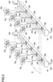
- Fig. 5 is a schematic diagram illustrating a second example of the hydroponics device according to the present invention.
- the hydroponics device includes a delivery channel 42 and a delivery channel 44.
- the delivery channel 42 is provided for taproots 28a of a group of plants 28 P1 , 28 P2 , 28 P3 and 28 P4 and holds a predetermined quantity of the nutrient solution LQ1.
- the delivery channel 44 is provided for taproots 28a of a group of plants 28 P5 , 28 P6 , 28 P7 and 28 P5 and holds a predetermined quantity of the nutrient solution LQ1.
- the hydroponics device shown in Fig. 5 includes the cover support 10C, the tank 12 and the pump 12P provided to the example shown in Fig. 2 .
- solar plant factories or closed plant factories using artificial light are equipped with multistage cultivation shelves (not shown) on which a plurality of hydroponics devices are arranged.
- Fig. 5 shows one representative hydroponics device.
- the delivery channels 42 and 44 have the same structure, the following description mainly explains the delivery channel 42 and omits explanation of the delivery channel 44.
- the delivery channel 42 which is shaped like a gutter, has an interior as a reservoir for holding a predetermined quantity of the nutrient solution LQ1 supplied from the tank 12 via the supply path Du2.
- the reservoir has a top that is open to the growth space 10A mentioned above.
- the other end of the supply path Du2 is open to the liquid surface of the nutrient solution LQ1 in the reservoir.
- an open end of a discharge pipe protrudes by a predetermined length.
- the open end of the discharge pipe serving as a liquid level control means has a protrusion length which is set, for example, to about 3 cm.
- the liquid level of the nutrient solution LQ1 rises, the nutrient solution LQ1 is discharged to the return discharge path Du1, which is ensured to communicate with the tank 12, via the discharge pipe. Therefore, the liquid level of the nutrient solution LQ1 is controlled to a predetermined liquid level LH corresponding to the predetermined length of the taproots 28a of the plants.
- the plants 28 P1 , 28 P2 , 28 P3 , 28 P4 , 28 P5 ... and 28 Pn can be grown.
- this configuration can reduce the quantity of the nutrient solution LQ1 circulated in the delivery channels 42 and 44 compared to the quantity of the nutrient solution LQ1 circulated in the pan 10B shown in Fig. 2 .
- the quantity of the nutrient solution LQ1 used can be reduced.
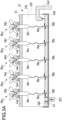
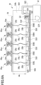
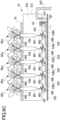
- Figs. 6A , 6B and 6C are schematic diagrams each illustrating a third example of the hydroponics device according to the present invention.
- the hydroponics device includes cultivation containers 50B1, 50B2, 50B3, 50B4 and 50B5 filled with a predetermined quantity of the nutrient solution LQ1 and respectively provided for taproots 28a of the plants 28 P1 , 28 P2 , 28 P3 , 28 P4 , 28 P4 and 28 P5 .
- solar plant factories or closed plant factories using artificial light are equipped with multistage cultivation shelves (not shown) on which a plurality of hydroponics devices are arranged.
- Fig. 6A shows one representative hydroponics device.
- the hydroponics device includes, for example, a tank 12, a pump 12P, a support table 50D, cultivation containers 50B1, 50B2, 50B3, 50B4 and 50B5, a cover 54, and a cover support 50C.
- the tank 12 stores a nutrient solution LQ1 that is a liquid fertilizer whose concentration has been adjusted to a predetermined level.
- the pump 12P is disposed in the tank 12 and supplies the nutrient solution LQ1 in the tank 12 to a supply path Du2 described later.
- the support table 50D forms a lower part of a cultivation planter 50.
- the cultivation containers 50B1, 50B2, 50B3, 50B4 and 50B5 are supported by the support table 50D and hold a predetermined quantity of the nutrient solution LQ1.
- the cover 54 forms an upper part of the cultivation planter 50.
- the cover support 50C supports the cover 54 from beneath the cover 54.
- the cover 54 supports the plants 28 P1 , 28 P2 , 28 P3 , 28 P4 , 28 P5 ... and 28 Pn , which are a predetermined number of different strains of the same species, via respective plant fixing stoppers 54a serving as pads, which will be described later, so that tips 28b of taproots 28a of the plants are immersed in the nutrient solution LQ1 in the respective cultivation containers 50B1, 50B2, 50B3, 50B4 and SOBS.
- the plant fixing stoppers 54a are arranged at positions corresponding to openings of the cover 54.
- the plurality of openings of the cover 54 are formed in a matrix at predetermined intervals.
- the plant fixing stoppers 54a each include, on the inside thereof, a seal holder in which a plurality of sealing members are held being overlaid with each other.
- the plant fixing stoppers 14a may be members, such as urethane sponge mats, having flexibility and stretchability.
- shoots 28c of the plants 28 P1 , 28 P2 , 28 P3 , 28 P4 and 28 P5 can be supported in the cover 54 by the respective plant fixing stoppers 54a.
- the cover support 50C has a growth space 50A on the inside thereof for holding dilating portions 48c in the roots of grown plants 48 P1 , 48 P2 , 48 P3 , 48 P4 and 48 P5 .
- the growth space (air layer) 50A has a height HA exceeding the length in the elongation growth direction of the dilating portions 48c in the roots of the grown plants 48 P1 , 48 P2 , 48 P3 , 48 P4 and 48 P5 at the time of harvest.
- the height HA is set to 50 cm or more.
- the height HA may be set to a predetermined height of less than 50 cm depending on the lengths in the elongation growth direction of the dilating portions in the roots of grown plants of different species at the time of harvest.
- the height HA may be set to a value in the range of about 20 cm or more and 30 cm or less.
- the pump 12P in the tank 12, which serves as a nutrient solution storage, is controlled by a control unit, not shown.
- the control unit uses a detection output signal derived from a liquid level sensor LS provided in a sub-tank 50T.
- the liquid level sensor LS includes three level-detection terminals having different lengths.
- the control unit deactivates the pump 12P based on the detection output signal derived from the liquid level sensor LS. It should be noted that the longest level-detection terminal serves as a common terminal.
- the cultivation containers 50B 1, 50B2, 50B3, 50B4 and 50B5 have reservoirs which are ensured to communicate with each other via respective communication paths 50P.
- the cultivation container SOBS has a reservoir which is ensured to communicate with the sub-tank 50T via a communication path 50P.
- the reservoirs respectively have tops that are open to the growth space 50A mentioned above.
- the other end of the supply path Du2 is open to the surface of the nutrient solution LQ1 in the reservoir of the sub-tank 50T. Accordingly, the liquid level of the nutrient solution LQ1 in the reservoirs of the cultivation containers 50B1, 50B2, 50B3, 50B4 and 50B5 is controlled according to the liquid level in the sub-tank 50T.
- the plants 28 P1 , 28 P2 , 28 P3 , 28 P4 , 28 P5 ... and 28 Pn arranged in the cultivation planter 50 gradually grow.
- dilating portions 38c in the roots grow even more than the shoots 28c. This growth is considered to be due to drought stress in the growth space (air layer) 50A.
- Plants 38 P1 , 38 P2 , 38 P3 , 38 P4 , 38 P5 ... and 38 Pn have grown leaves 38d above the dilating portions 38c in the roots and elongated taproots 38a below the dilating portions 38c in the roots. Tips 38b of the taproots 38a are immersed in the nutrient solution LQ1.
- the plants 38 P1 , 38 P2 , 38 P3 , 38 P4 , 38 P5 ... and 38 Pn when they have grown even more and are going to be harvested, will have dilating portions 48c in the roots with diameters and lengths, as shown in Fig. 6C , which are larger than those of the dilating portions 38c in the roots mentioned above.
- Plants 48 P1 , 48 P2 , 48 P3 , 48 P4 , 48 P5 ... and 48 Pn have grown leaves 48d above the dilating portions 48c in the roots and elongated taproots 48a below the dilating portions 48c of the roots. Tips 48b of the taproots 48a are immersed in the nutrient solution LQ1. In this way, no drain is required and the amount of nutrient solution required can be greatly reduced.
- plants are cultivated by separating the elongation growth of the roots of the plants from the thickening growth of the roots. Accordingly, at the seedling stage where the plants are lightweight and can be cultivated in a small space, it is easy to efficiently grow long seedlings without using a large tank. At the stage where the roots of the plants dilate, increase in weight and are difficult to transfer, only the tips of the roots of the plants have to be immersed in a small quantity of nutrient solution. Thus, if only a suitable space is available, cultivation of root vegetables can be realized. There is no need for a large tank or means for holding a large quantity of liquid.
- root vegetables can be sufficiently cultivated using hydroponics devices which are used for cultivation of leafy vegetables (lettuce) with liquid 3 cm deep. Therefore, there is no need for newly developing hydroponics devices dedicated to root vegetables. It has been considered that a large tank and a large quantity of liquid are indispensable for cultivation of root vegetables. However, they are no longer necessary. Root vegetables, such as medical plants (for use as Chinese medicines or herbal medicines), store active ingredients in the roots. Therefore, besides usage as food, root vegetables are expected to be grown for the purpose of using such active ingredients stored in the roots as products. Development of a low-cost cultivation method can contribute to providing chemical-free root vegetables which ensure stable content of active ingredients due to control of cultivation environments.
Landscapes
- Life Sciences & Earth Sciences (AREA)
- Environmental Sciences (AREA)
- Hydroponics (AREA)
Claims (10)
- Hydrokultur-Vorrichtung, umfassend:einen Nährstofflösung-Speicher (12), in welchem eine Nährstofflösung (LQ1) gespeichert ist;einen Nährstofflösung-Vorratsbehälter (10B), in welchen die Nährstofflösung (LQ1) von dem Nährstofflösung-Speicher geliefert wird; undeine Abdeckung (14), welche eine Mehrzahl von Pflanzen (28P1, 28P2, 28P3, 28P4, 28P5) trägt, welche zu kultivieren sind, wobei die Abdeckung (14) fest von einer Flüssigkeitsoberfläche der Nährstofflösung (LQ1) in dem Nährstofflösung-Vorratsbehälter (10B) beabstandet ist, wobei eine vorbestimmte Distanz zwischen der Abdeckung (14) und der Flüssigkeitsoberfläche sichergestellt ist, dadurch gekennzeichnet, dass:die von der Abdeckung (14) getragenen Pflanzen jeweils Pfahlwurzeln (28a) aufweisen, welche länger als die Längen von Trieben (28c) der Pflanzen sind,wobei die Pfahlwurzeln (28a) jeweilige Spitzen (28b) aufweisen, welche jeweils Wurzelhauben und apikale Meristeme umfassen, wobei lediglich die Spitzen (28B) in die Nährstofflösung (LQ1) in dem Nährstofflösung-Vorratsbehälter (10B) eingetaucht sind;die Vorrichtung eine Luftschicht (10A) umfasst, welche zwischen der Abdeckung (14) und der Flüssigkeitsoberfläche der Nährstofflösung (LQ1) in dem Nährstofflösung-Vorratsbehälter (10B) gebildet ist, um so die Pfahlwurzeln (28a) außer den Spitzen (28b) der Pfahlwurzeln (28a) zu umgeben, undwobei die Luftschicht (10A) eine vorbestimmte Höhe (HA) aufweist.
- Hydrokultur-Vorrichtung nach Anspruch 1, dadurch gekennzeichnet, dass der Nährstofflösung-Vorratsbehälter eine Pfanne ist.
- Hydrokultur-Vorrichtung nach Anspruch 1, dadurch gekennzeichnet, dass der Nährstofflösung-Vorratsbehälter ein Lieferkanal ist.
- Hydrokultur-Vorrichtung nach Anspruch 1, dadurch gekennzeichnet, dass der Nährstofflösung-Vorratsbehälter ein eigenständiger Kultivierungsbehälter ist, welcher für Pflanzen bereitgestellt ist.
- Hydrokultur-Vorrichtung nach Anspruch 1, dadurch gekennzeichnet, dass die Pflanzen jeweilige sich aufweitende Abschnitte in Wurzeln aufweisen, wobei die sich aufweitenden Abschnitte in einem Raum zwischen der Abdeckung und dem Nährstofflösung-Vorratsbehälter gebildet sind.
- Hydrokultur-Vorrichtung nach Anspruch 1, dadurch gekennzeichnet, dass die Luftschicht zwischen der Abdeckung und dem Nährstofflösung-Vorratsbehälter durch eine transparente oder lichtdurchlässige Bahn umschlossen ist.
- Hydrokultur-Vorrichtung nach Anspruch 1, dadurch gekennzeichnet, dass die Luftschicht zwischen der Abdeckung und dem Nährstofflösung-Vorratsbehälter durch eine Bahn umschlossen ist.
- Hydrokultur-Vorrichtung nach Anspruch 1, dadurch gekennzeichnet, dass eine Distanz zwischen der Abdeckung und der Flüssigkeitsoberfläche der Nährstofflösung in dem Nährstofflösung-Vorratsbehälter auf eine gewünschte Länge gemäß einem Wachstum der Pfahlwurzeln steuerbar ist.
- Hydrokultur-Verfahren, dadurch gekennzeichnet, dass das Verfahren die Schritte umfasst:Kultivieren von Pflanzen (28P1, 28P2, 28P3, 28P4, 28P5) in einem ersten Nährstofflösung-Vorratsbehälter, wobei die Pflanzen Pfahlwurzeln (28a) aufweisen, welche länger als die Längen von entsprechenden Trieben (28c) der Pflanzen sind;Aufziehen der Pflanzen, welche in dem ersten Nährstofflösung-Vorratsbehälter kultiviert werden, in einem zweiten Nährstofflösung-Vorratsbehälter, in welchem eine Luftschicht (10A) um Abschnitte der Pfahlwurzeln (28a) der entsprechenden Pflanzen, außer Spitzen (28b) der Pfahlwurzeln (28a), herum gebildet ist, welche jeweils Wurzelhauben und apikale Meristeme umfassen, wobei die Luftschicht (10A) eine vorbestimmte Höhe (HA) aufweist, undwobei lediglich die Spitzen (28b) der Pfahlwurzeln (28a) der entsprechenden Pflanzen in der Nährstofflösung in dem ersten Nährstofflösung-Vorratsbehälter und dem zweiten Nährstofflösung-Vorratsbehälter eingetaucht sind.
- Hydrokultur-Verfahren nach Anspruch 9, dadurch gekennzeichnet, dass in dem Schritt des Kultivierens von Pflanzen in einem ersten Nährstofflösung-Vorratsbehälter die Pflanzen Pfahlwurzeln aufweisen, welche länger als die Längen von entsprechenden Trieben der Pflanzen sind, wobei lediglich die Spitzen der Pfahlwurzeln der Pflanzen in der Nährstofflösung in dem ersten Nährstofflösung-Vorratsbehälter gemäß einem Wachstum der Pfahlwurzeln eingetaucht sind.
Applications Claiming Priority (2)
| Application Number | Priority Date | Filing Date | Title |
|---|---|---|---|
| JP2017218319 | 2017-11-13 | ||
| PCT/JP2018/041447 WO2019093410A1 (ja) | 2017-11-13 | 2018-11-08 | 水耕栽培装置、および、水耕栽培方法 |
Publications (3)
| Publication Number | Publication Date |
|---|---|
| EP3711477A1 EP3711477A1 (de) | 2020-09-23 |
| EP3711477A4 EP3711477A4 (de) | 2020-12-23 |
| EP3711477B1 true EP3711477B1 (de) | 2024-07-17 |
Family
ID=66438374
Family Applications (1)
| Application Number | Title | Priority Date | Filing Date |
|---|---|---|---|
| EP18876180.3A Active EP3711477B1 (de) | 2017-11-13 | 2018-11-08 | Hydrokulturvorrichtung und hydrokulturverfahren |
Country Status (7)
| Country | Link |
|---|---|
| US (1) | US20200260672A1 (de) |
| EP (1) | EP3711477B1 (de) |
| JP (1) | JP7276138B2 (de) |
| KR (1) | KR102718193B1 (de) |
| CN (1) | CN111343860B (de) |
| ES (1) | ES2984858T3 (de) |
| WO (1) | WO2019093410A1 (de) |
Families Citing this family (6)
| Publication number | Priority date | Publication date | Assignee | Title |
|---|---|---|---|---|
| US20210007306A1 (en) * | 2019-07-12 | 2021-01-14 | Harvest2o LLC | Hydroponic system for growing multiple types of plants |
| EP4167340A4 (de) | 2020-07-08 | 2023-12-06 | LG Energy Solution, Ltd. | Verfahren zur herstellung einer feststoffbatterie mit einem feststoffelektrolytmaterial |
| IL279007B2 (en) * | 2020-11-26 | 2023-04-01 | Green Bubble Ltd | Method and device for cultivating plants |
| JP7276907B2 (ja) * | 2021-06-21 | 2023-05-18 | 株式会社エコタイプ次世代植物工場 | オタネニンジンの養液栽培方法 |
| CN114931090A (zh) * | 2022-06-01 | 2022-08-23 | 颜斌 | 一种可智能调控的栽培装置 |
| CN116076349B (zh) * | 2023-04-10 | 2023-06-23 | 山东世伟工贸有限公司 | 一种温室水槽 |
Family Cites Families (20)
| Publication number | Priority date | Publication date | Assignee | Title |
|---|---|---|---|---|
| US2189510A (en) * | 1938-06-16 | 1940-02-06 | Ellis Lab Inc | Hydroculture plant box |
| US3660933A (en) * | 1970-03-02 | 1972-05-09 | Weingarten & Wong Enterprises | Hydroponics system and method |
| US3868787A (en) * | 1971-12-29 | 1975-03-04 | Weingarten & Wong Enterprises | Apparatus for supporting hydroponically grown plants |
| US4059922A (en) * | 1976-01-12 | 1977-11-29 | Digiacinto Joseph A | Sprayer hydroponic grower |
| US4932158A (en) * | 1988-05-25 | 1990-06-12 | Roberts David S | Method and apparatus for hydroponic gardening |
| JPH0494960U (de) * | 1991-01-14 | 1992-08-18 | ||
| JPH04258231A (ja) * | 1991-01-29 | 1992-09-14 | Kawashima Textile Manuf Ltd | 水耕栽培用繊維質シートおよび水耕栽培方法 |
| JP3477645B2 (ja) * | 2001-04-26 | 2003-12-10 | 株式会社生物機能工学研究所 | 露地水耕栽培用定植パネルの防雨カバー装置 |
| JP2007061002A (ja) * | 2005-08-31 | 2007-03-15 | Soatec Inc | 水耕栽培用の養液槽 |
| CN103039339A (zh) * | 2012-12-24 | 2013-04-17 | 何寒 | 一种植物水培生产装置 |
| JP5608799B1 (ja) * | 2013-09-12 | 2014-10-15 | パナソニック株式会社 | 水耕栽培装置 |
| JP5807209B2 (ja) * | 2013-09-26 | 2015-11-10 | パナソニックIpマネジメント株式会社 | 水耕栽培装置 |
| JP2015139410A (ja) * | 2014-01-29 | 2015-08-03 | パナソニックIpマネジメント株式会社 | 水耕栽培装置 |
| NL2012234C2 (en) * | 2014-02-10 | 2015-08-17 | Vivi B V | Plant holder. |
| TW201543993A (zh) * | 2014-05-30 | 2015-12-01 | Yaskawa Denki Seisakusho Kk | 植物栽培單元、單元保持具、植物栽培單元的製造方法、及植物栽培方法 |
| JP6391004B2 (ja) * | 2014-09-03 | 2018-09-19 | パナソニックIpマネジメント株式会社 | 水耕栽培装置 |
| JP6604465B2 (ja) * | 2014-12-24 | 2019-11-13 | パナソニックIpマネジメント株式会社 | 水耕栽培装置 |
| US20170196176A1 (en) * | 2015-03-04 | 2017-07-13 | Jack Griffin | High density indoor farming apparatus, system and method |
| JP2016178887A (ja) * | 2015-03-24 | 2016-10-13 | 株式会社タムロン | 水耕栽培装置、植物工場、及び、水耕栽培方法 |
| JP6919160B2 (ja) | 2015-08-05 | 2021-08-18 | 凸版印刷株式会社 | 栽培用容器、および、それを備える栽培システム |
-
2018
- 2018-11-08 EP EP18876180.3A patent/EP3711477B1/de active Active
- 2018-11-08 ES ES18876180T patent/ES2984858T3/es active Active
- 2018-11-08 KR KR1020207010800A patent/KR102718193B1/ko active Active
- 2018-11-08 JP JP2019552369A patent/JP7276138B2/ja active Active
- 2018-11-08 WO PCT/JP2018/041447 patent/WO2019093410A1/ja not_active Ceased
- 2018-11-08 CN CN201880073047.7A patent/CN111343860B/zh active Active
-
2020
- 2020-05-07 US US16/868,725 patent/US20200260672A1/en not_active Abandoned
Also Published As
| Publication number | Publication date |
|---|---|
| US20200260672A1 (en) | 2020-08-20 |
| JPWO2019093410A1 (ja) | 2020-11-19 |
| WO2019093410A1 (ja) | 2019-05-16 |
| CN111343860B (zh) | 2022-07-08 |
| KR20200084326A (ko) | 2020-07-10 |
| EP3711477A1 (de) | 2020-09-23 |
| EP3711477A4 (de) | 2020-12-23 |
| CN111343860A (zh) | 2020-06-26 |
| ES2984858T3 (es) | 2024-10-31 |
| JP7276138B2 (ja) | 2023-05-18 |
| KR102718193B1 (ko) | 2024-10-17 |
Similar Documents
| Publication | Publication Date | Title |
|---|---|---|
| EP3711477A1 (de) | Hydrokulturvorrichtung und hydrokulturverfahren | |
| CN207767002U (zh) | 用于柑橘育苗的栽培装置 | |
| CN203723212U (zh) | 实验用叶类蔬菜水培装置 | |
| US20120186151A1 (en) | Method for cultivating one or more plants | |
| CN208875040U (zh) | 一种植物种子或幼苗水培装置 | |
| CN207665720U (zh) | 一种海绵板水培育苗装置 | |
| JPH05284864A (ja) | 溶液栽培によるジャガイモの種芋生産方法 | |
| KR101740571B1 (ko) | 씨감자 생산용 순환식 담액수경 장치와 이를 이용한 재배방법 | |
| CN107593310A (zh) | 一种玉米培育种植方法 | |
| CN107624594A (zh) | 一种豌豆培育种植方法 | |
| CN211909818U (zh) | 一种白玉翠黄瓜栽培架 | |
| JP5981494B2 (ja) | 植物栽培万能ポットと収納トレー | |
| KR20170126640A (ko) | 수경산삼 재배장치 | |
| JP2018064462A (ja) | 栽培装置、栽培方法 | |
| CN213343534U (zh) | 一种作物移栽的种子育苗装置 | |
| JP2020110085A (ja) | 植物栽培方法、植物栽培施設、及び水処理装置 | |
| CN210298913U (zh) | 一种新型水培蔬菜育苗种植盆 | |
| CN210298711U (zh) | 一种水培与土培相结合的蔬菜种植袋 | |
| CN110537483A (zh) | 绿叶蔬菜沙基质栽培生产系统 | |
| CN210328852U (zh) | 一种兼具育苗功能的水培蔬菜种植盆 | |
| JP3781275B2 (ja) | 連結プラグを用いる葉菜類の軽石栽培方法 | |
| CN210928789U (zh) | 一种育苗装置 | |
| JPH08103179A (ja) | 乳苗の育成方法 | |
| CN210959629U (zh) | 一种水稻育秧架 | |
| JPH1041A (ja) | ゴボウの水耕栽培方法及び装置 |
Legal Events
| Date | Code | Title | Description |
|---|---|---|---|
| STAA | Information on the status of an ep patent application or granted ep patent |
Free format text: STATUS: THE INTERNATIONAL PUBLICATION HAS BEEN MADE |
|
| PUAI | Public reference made under article 153(3) epc to a published international application that has entered the european phase |
Free format text: ORIGINAL CODE: 0009012 |
|
| STAA | Information on the status of an ep patent application or granted ep patent |
Free format text: STATUS: REQUEST FOR EXAMINATION WAS MADE |
|
| 17P | Request for examination filed |
Effective date: 20200422 |
|
| AK | Designated contracting states |
Kind code of ref document: A1 Designated state(s): AL AT BE BG CH CY CZ DE DK EE ES FI FR GB GR HR HU IE IS IT LI LT LU LV MC MK MT NL NO PL PT RO RS SE SI SK SM TR |
|
| AX | Request for extension of the european patent |
Extension state: BA ME |
|
| REG | Reference to a national code |
Ref country code: DE Ref legal event code: R079 Free format text: PREVIOUS MAIN CLASS: A01G0031000000 Ipc: A01G0031020000 Ref country code: DE Ref legal event code: R079 Ref document number: 602018071997 Country of ref document: DE Free format text: PREVIOUS MAIN CLASS: A01G0031000000 Ipc: A01G0031020000 |
|
| A4 | Supplementary search report drawn up and despatched |
Effective date: 20201124 |
|
| RIC1 | Information provided on ipc code assigned before grant |
Ipc: A01G 31/02 20060101AFI20201118BHEP Ipc: A01G 31/06 20060101ALI20201118BHEP |
|
| DAV | Request for validation of the european patent (deleted) | ||
| DAX | Request for extension of the european patent (deleted) | ||
| STAA | Information on the status of an ep patent application or granted ep patent |
Free format text: STATUS: EXAMINATION IS IN PROGRESS |
|
| 17Q | First examination report despatched |
Effective date: 20230623 |
|
| GRAP | Despatch of communication of intention to grant a patent |
Free format text: ORIGINAL CODE: EPIDOSNIGR1 |
|
| STAA | Information on the status of an ep patent application or granted ep patent |
Free format text: STATUS: GRANT OF PATENT IS INTENDED |
|
| INTG | Intention to grant announced |
Effective date: 20240207 |
|
| GRAS | Grant fee paid |
Free format text: ORIGINAL CODE: EPIDOSNIGR3 |
|
| GRAA | (expected) grant |
Free format text: ORIGINAL CODE: 0009210 |
|
| STAA | Information on the status of an ep patent application or granted ep patent |
Free format text: STATUS: THE PATENT HAS BEEN GRANTED |
|
| AK | Designated contracting states |
Kind code of ref document: B1 Designated state(s): AL AT BE BG CH CY CZ DE DK EE ES FI FR GB GR HR HU IE IS IT LI LT LU LV MC MK MT NL NO PL PT RO RS SE SI SK SM TR |
|
| REG | Reference to a national code |
Ref country code: CH Ref legal event code: EP |
|
| REG | Reference to a national code |
Ref country code: DE Ref legal event code: R096 Ref document number: 602018071997 Country of ref document: DE |
|
| REG | Reference to a national code |
Ref country code: IE Ref legal event code: FG4D |
|
| REG | Reference to a national code |
Ref country code: NL Ref legal event code: FP |
|
| REG | Reference to a national code |
Ref country code: ES Ref legal event code: FG2A Ref document number: 2984858 Country of ref document: ES Kind code of ref document: T3 Effective date: 20241031 |
|
| REG | Reference to a national code |
Ref country code: LT Ref legal event code: MG9D |
|
| PG25 | Lapsed in a contracting state [announced via postgrant information from national office to epo] |
Ref country code: PT Free format text: LAPSE BECAUSE OF FAILURE TO SUBMIT A TRANSLATION OF THE DESCRIPTION OR TO PAY THE FEE WITHIN THE PRESCRIBED TIME-LIMIT Effective date: 20241118 |
|
| REG | Reference to a national code |
Ref country code: AT Ref legal event code: MK05 Ref document number: 1703224 Country of ref document: AT Kind code of ref document: T Effective date: 20240717 |
|
| PG25 | Lapsed in a contracting state [announced via postgrant information from national office to epo] |
Ref country code: PT Free format text: LAPSE BECAUSE OF FAILURE TO SUBMIT A TRANSLATION OF THE DESCRIPTION OR TO PAY THE FEE WITHIN THE PRESCRIBED TIME-LIMIT Effective date: 20241118 |
|
| PG25 | Lapsed in a contracting state [announced via postgrant information from national office to epo] |
Ref country code: NO Free format text: LAPSE BECAUSE OF FAILURE TO SUBMIT A TRANSLATION OF THE DESCRIPTION OR TO PAY THE FEE WITHIN THE PRESCRIBED TIME-LIMIT Effective date: 20241017 |
|
| PG25 | Lapsed in a contracting state [announced via postgrant information from national office to epo] |
Ref country code: GR Free format text: LAPSE BECAUSE OF FAILURE TO SUBMIT A TRANSLATION OF THE DESCRIPTION OR TO PAY THE FEE WITHIN THE PRESCRIBED TIME-LIMIT Effective date: 20241018 Ref country code: FI Free format text: LAPSE BECAUSE OF FAILURE TO SUBMIT A TRANSLATION OF THE DESCRIPTION OR TO PAY THE FEE WITHIN THE PRESCRIBED TIME-LIMIT Effective date: 20240717 Ref country code: PL Free format text: LAPSE BECAUSE OF FAILURE TO SUBMIT A TRANSLATION OF THE DESCRIPTION OR TO PAY THE FEE WITHIN THE PRESCRIBED TIME-LIMIT Effective date: 20240717 |
|
| PG25 | Lapsed in a contracting state [announced via postgrant information from national office to epo] |
Ref country code: BG Free format text: LAPSE BECAUSE OF FAILURE TO SUBMIT A TRANSLATION OF THE DESCRIPTION OR TO PAY THE FEE WITHIN THE PRESCRIBED TIME-LIMIT Effective date: 20240717 |
|
| PG25 | Lapsed in a contracting state [announced via postgrant information from national office to epo] |
Ref country code: LV Free format text: LAPSE BECAUSE OF FAILURE TO SUBMIT A TRANSLATION OF THE DESCRIPTION OR TO PAY THE FEE WITHIN THE PRESCRIBED TIME-LIMIT Effective date: 20240717 |
|
| PG25 | Lapsed in a contracting state [announced via postgrant information from national office to epo] |
Ref country code: IS Free format text: LAPSE BECAUSE OF FAILURE TO SUBMIT A TRANSLATION OF THE DESCRIPTION OR TO PAY THE FEE WITHIN THE PRESCRIBED TIME-LIMIT Effective date: 20241117 Ref country code: AT Free format text: LAPSE BECAUSE OF FAILURE TO SUBMIT A TRANSLATION OF THE DESCRIPTION OR TO PAY THE FEE WITHIN THE PRESCRIBED TIME-LIMIT Effective date: 20240717 |
|
| PG25 | Lapsed in a contracting state [announced via postgrant information from national office to epo] |
Ref country code: HR Free format text: LAPSE BECAUSE OF FAILURE TO SUBMIT A TRANSLATION OF THE DESCRIPTION OR TO PAY THE FEE WITHIN THE PRESCRIBED TIME-LIMIT Effective date: 20240717 |
|
| PG25 | Lapsed in a contracting state [announced via postgrant information from national office to epo] |
Ref country code: RS Free format text: LAPSE BECAUSE OF FAILURE TO SUBMIT A TRANSLATION OF THE DESCRIPTION OR TO PAY THE FEE WITHIN THE PRESCRIBED TIME-LIMIT Effective date: 20241017 |
|
| PG25 | Lapsed in a contracting state [announced via postgrant information from national office to epo] |
Ref country code: RS Free format text: LAPSE BECAUSE OF FAILURE TO SUBMIT A TRANSLATION OF THE DESCRIPTION OR TO PAY THE FEE WITHIN THE PRESCRIBED TIME-LIMIT Effective date: 20241017 Ref country code: PL Free format text: LAPSE BECAUSE OF FAILURE TO SUBMIT A TRANSLATION OF THE DESCRIPTION OR TO PAY THE FEE WITHIN THE PRESCRIBED TIME-LIMIT Effective date: 20240717 Ref country code: NO Free format text: LAPSE BECAUSE OF FAILURE TO SUBMIT A TRANSLATION OF THE DESCRIPTION OR TO PAY THE FEE WITHIN THE PRESCRIBED TIME-LIMIT Effective date: 20241017 Ref country code: LV Free format text: LAPSE BECAUSE OF FAILURE TO SUBMIT A TRANSLATION OF THE DESCRIPTION OR TO PAY THE FEE WITHIN THE PRESCRIBED TIME-LIMIT Effective date: 20240717 Ref country code: IS Free format text: LAPSE BECAUSE OF FAILURE TO SUBMIT A TRANSLATION OF THE DESCRIPTION OR TO PAY THE FEE WITHIN THE PRESCRIBED TIME-LIMIT Effective date: 20241117 Ref country code: HR Free format text: LAPSE BECAUSE OF FAILURE TO SUBMIT A TRANSLATION OF THE DESCRIPTION OR TO PAY THE FEE WITHIN THE PRESCRIBED TIME-LIMIT Effective date: 20240717 Ref country code: GR Free format text: LAPSE BECAUSE OF FAILURE TO SUBMIT A TRANSLATION OF THE DESCRIPTION OR TO PAY THE FEE WITHIN THE PRESCRIBED TIME-LIMIT Effective date: 20241018 Ref country code: FI Free format text: LAPSE BECAUSE OF FAILURE TO SUBMIT A TRANSLATION OF THE DESCRIPTION OR TO PAY THE FEE WITHIN THE PRESCRIBED TIME-LIMIT Effective date: 20240717 Ref country code: BG Free format text: LAPSE BECAUSE OF FAILURE TO SUBMIT A TRANSLATION OF THE DESCRIPTION OR TO PAY THE FEE WITHIN THE PRESCRIBED TIME-LIMIT Effective date: 20240717 Ref country code: AT Free format text: LAPSE BECAUSE OF FAILURE TO SUBMIT A TRANSLATION OF THE DESCRIPTION OR TO PAY THE FEE WITHIN THE PRESCRIBED TIME-LIMIT Effective date: 20240717 |
|
| PG25 | Lapsed in a contracting state [announced via postgrant information from national office to epo] |
Ref country code: SM Free format text: LAPSE BECAUSE OF FAILURE TO SUBMIT A TRANSLATION OF THE DESCRIPTION OR TO PAY THE FEE WITHIN THE PRESCRIBED TIME-LIMIT Effective date: 20240717 Ref country code: DK Free format text: LAPSE BECAUSE OF FAILURE TO SUBMIT A TRANSLATION OF THE DESCRIPTION OR TO PAY THE FEE WITHIN THE PRESCRIBED TIME-LIMIT Effective date: 20240717 Ref country code: RO Free format text: LAPSE BECAUSE OF FAILURE TO SUBMIT A TRANSLATION OF THE DESCRIPTION OR TO PAY THE FEE WITHIN THE PRESCRIBED TIME-LIMIT Effective date: 20240717 |
|
| REG | Reference to a national code |
Ref country code: DE Ref legal event code: R097 Ref document number: 602018071997 Country of ref document: DE |
|
| PG25 | Lapsed in a contracting state [announced via postgrant information from national office to epo] |
Ref country code: EE Free format text: LAPSE BECAUSE OF FAILURE TO SUBMIT A TRANSLATION OF THE DESCRIPTION OR TO PAY THE FEE WITHIN THE PRESCRIBED TIME-LIMIT Effective date: 20240717 |
|
| PG25 | Lapsed in a contracting state [announced via postgrant information from national office to epo] |
Ref country code: CZ Free format text: LAPSE BECAUSE OF FAILURE TO SUBMIT A TRANSLATION OF THE DESCRIPTION OR TO PAY THE FEE WITHIN THE PRESCRIBED TIME-LIMIT Effective date: 20240717 |
|
| PG25 | Lapsed in a contracting state [announced via postgrant information from national office to epo] |
Ref country code: SK Free format text: LAPSE BECAUSE OF FAILURE TO SUBMIT A TRANSLATION OF THE DESCRIPTION OR TO PAY THE FEE WITHIN THE PRESCRIBED TIME-LIMIT Effective date: 20240717 |
|
| PLBE | No opposition filed within time limit |
Free format text: ORIGINAL CODE: 0009261 |
|
| STAA | Information on the status of an ep patent application or granted ep patent |
Free format text: STATUS: NO OPPOSITION FILED WITHIN TIME LIMIT |
|
| REG | Reference to a national code |
Ref country code: DE Ref legal event code: R119 Ref document number: 602018071997 Country of ref document: DE |
|
| 26N | No opposition filed |
Effective date: 20250422 |
|
| REG | Reference to a national code |
Ref country code: CH Ref legal event code: PL |
|
| PG25 | Lapsed in a contracting state [announced via postgrant information from national office to epo] |
Ref country code: MC Free format text: LAPSE BECAUSE OF FAILURE TO SUBMIT A TRANSLATION OF THE DESCRIPTION OR TO PAY THE FEE WITHIN THE PRESCRIBED TIME-LIMIT Effective date: 20240717 |
|
| PG25 | Lapsed in a contracting state [announced via postgrant information from national office to epo] |
Ref country code: LU Free format text: LAPSE BECAUSE OF NON-PAYMENT OF DUE FEES Effective date: 20241108 |
|
| REG | Reference to a national code |
Ref country code: CH Ref legal event code: PL |
|
| GBPC | Gb: european patent ceased through non-payment of renewal fee |
Effective date: 20241108 |
|
| PG25 | Lapsed in a contracting state [announced via postgrant information from national office to epo] |
Ref country code: CH Free format text: LAPSE BECAUSE OF NON-PAYMENT OF DUE FEES Effective date: 20241130 |
|
| REG | Reference to a national code |
Ref country code: BE Ref legal event code: MM Effective date: 20241130 |
|
| PG25 | Lapsed in a contracting state [announced via postgrant information from national office to epo] |
Ref country code: SE Free format text: LAPSE BECAUSE OF FAILURE TO SUBMIT A TRANSLATION OF THE DESCRIPTION OR TO PAY THE FEE WITHIN THE PRESCRIBED TIME-LIMIT Effective date: 20240717 |
|
| PG25 | Lapsed in a contracting state [announced via postgrant information from national office to epo] |
Ref country code: DE Free format text: LAPSE BECAUSE OF NON-PAYMENT OF DUE FEES Effective date: 20250603 |
|
| PG25 | Lapsed in a contracting state [announced via postgrant information from national office to epo] |
Ref country code: GB Free format text: LAPSE BECAUSE OF NON-PAYMENT OF DUE FEES Effective date: 20241108 Ref country code: BE Free format text: LAPSE BECAUSE OF NON-PAYMENT OF DUE FEES Effective date: 20241130 |
|
| PGFP | Annual fee paid to national office [announced via postgrant information from national office to epo] |
Ref country code: FR Payment date: 20250930 Year of fee payment: 8 |
|
| PG25 | Lapsed in a contracting state [announced via postgrant information from national office to epo] |
Ref country code: IE Free format text: LAPSE BECAUSE OF NON-PAYMENT OF DUE FEES Effective date: 20241108 |
|
| PGFP | Annual fee paid to national office [announced via postgrant information from national office to epo] |
Ref country code: NL Payment date: 20251003 Year of fee payment: 8 |
|
| PGFP | Annual fee paid to national office [announced via postgrant information from national office to epo] |
Ref country code: IT Payment date: 20251022 Year of fee payment: 8 |
|
| PGFP | Annual fee paid to national office [announced via postgrant information from national office to epo] |
Ref country code: ES Payment date: 20251209 Year of fee payment: 8 |
|
| PG25 | Lapsed in a contracting state [announced via postgrant information from national office to epo] |
Ref country code: HU Free format text: LAPSE BECAUSE OF FAILURE TO SUBMIT A TRANSLATION OF THE DESCRIPTION OR TO PAY THE FEE WITHIN THE PRESCRIBED TIME-LIMIT; INVALID AB INITIO Effective date: 20181108 |
|
| PG25 | Lapsed in a contracting state [announced via postgrant information from national office to epo] |
Ref country code: CY Free format text: LAPSE BECAUSE OF FAILURE TO SUBMIT A TRANSLATION OF THE DESCRIPTION OR TO PAY THE FEE WITHIN THE PRESCRIBED TIME-LIMIT; INVALID AB INITIO Effective date: 20181108 |