EP3711472A1 - Tastbügel - Google Patents
Tastbügel Download PDFInfo
- Publication number
- EP3711472A1 EP3711472A1 EP19213858.4A EP19213858A EP3711472A1 EP 3711472 A1 EP3711472 A1 EP 3711472A1 EP 19213858 A EP19213858 A EP 19213858A EP 3711472 A1 EP3711472 A1 EP 3711472A1
- Authority
- EP
- European Patent Office
- Prior art keywords
- sensing bracket
- section
- bracket
- upper section
- sensing
- Prior art date
- Legal status (The legal status is an assumption and is not a legal conclusion. Google has not performed a legal analysis and makes no representation as to the accuracy of the status listed.)
- Granted
Links
Images

Classifications
-
- A—HUMAN NECESSITIES
- A01—AGRICULTURE; FORESTRY; ANIMAL HUSBANDRY; HUNTING; TRAPPING; FISHING
- A01D—HARVESTING; MOWING
- A01D41/00—Combines, i.e. harvesters or mowers combined with threshing devices
- A01D41/12—Details of combines
- A01D41/14—Mowing tables
- A01D41/141—Automatic header control
Definitions
- the present invention relates to a feeler bracket for an attachment, in particular a cutter, the feeler bracket having an elongated body, with a receptacle extending transversely to the longitudinal axis being arranged at one end of the elongate body for the implementation of a shaft about which the probe bracket can be pivoted, wherein an opposite free end can be guided over a floor for scanning.
- Front attachments are carried by an agricultural harvesting machine and driven across a field to be harvested in order to cut off the harvested crop and feed it to the harvesting machine for further processing. It is necessary to keep the distance between the attachment and the field soil as constant as possible in order to achieve a uniform cutting height.
- rigid feeler bars To continuously determine the detection of the distance between the attachment and the field floor, it is known to arrange rigid feeler bars on the attachment.
- the sensing arms have an elongated body, at one end of the elongated body a transverse receptacle to the longitudinal axis is arranged for the implementation of a shaft around which the sensing arm can be pivoted, while an opposite, free end of the body can be guided over a floor for scanning .
- the swiveling movement of the sensing bracket is recorded in order to determine the distance.
- the body In order to press the free end against the field floor, the body is spring-loaded at the pivot point.
- the free end of the feeler bar is curved in order to counteract piercing into the field soil when the harvester travels backwards.
- a chain is used to limit the pivoting angle and to protect the feeler bar, which is attached to the free end of the feeler bar and to the frame of the attachment.
- the chain is disadvantageous in that it can hang on this stalks, which can result in the failure of the floor guide function and damage to the sensing bracket or the sensor.
- the curved shape of the free end and the chain cannot always prevent damage to one of the feeler bars when reversing or cornering.
- a sensing bracket of the type mentioned which has an elongated body consisting of a plurality of shaft elements, adjacent shaft elements being connected to one another pivotably about an axis extending transversely to the longitudinal axis of the body.
- a cable is provided on which the shaft elements are drawn in a row.
- Such a feeler bracket has a very complex structure, which makes it expensive to manufacture.
- stalks can get stuck between the individual shaft elements, which has a negative impact on the functionality of the feeler bracket.
- the present invention is based on the object of developing a feeler bracket of the type mentioned at the beginning in such a way that the disadvantages mentioned at the beginning are avoided, in particular that the feeler bracket is characterized by a simpler structure.
- a feeler bracket for an attachment in particular a cutter, is proposed, the probe bracket loaded by a spring force having an elongated body, with a receptacle extending transversely to the longitudinal axis being arranged at one end of the elongate body for the implementation of a shaft which the sensing bracket is pivotable, and wherein an opposite free end can be guided over a floor for scanning.
- the body is divided into at least three sections, an upper section, on which the receptacle is arranged, and a lower section, which forms the free, the floor-scanning end of the sensing bracket, are rigid and an intermediate section, the is arranged between the upper section and the lower section and connects them to one another, is designed to be flexible.
- a chain is not attached to the third section, so that the problem of picking up stalks is avoided.
- the sections of the body are designed so that the sensing bracket in the vertical direction, in which the spring force acts on the body, is sufficiently rigid to prevent sagging due to the spring force.
- the intermediate section enables reversible lateral pivoting or folding about an axis running in the vertical direction when reversing or when cornering.
- the sensing bracket can be protected from damage.
- the quality of the distance measurement is prevented from being influenced by jumping or bending of the sensing bracket.
- the intermediate section can have a greater extent in the vertical direction of the body than in the transverse direction.
- An extension running along a longitudinal axis of the body is referred to as the longitudinal direction.
- the body has a longitudinal extent in the longitudinal direction.
- the transverse direction denotes an extension running perpendicular to the longitudinal axis of the body.
- the body has a width extension in the transverse direction.
- the vertical direction denotes an extension running perpendicular to the longitudinal axis of the body, which extends perpendicular to the plane of the longitudinal and transverse directions. Due to the greater extent in the vertical direction than in the transverse direction, the intermediate section has a high geometrical moment of inertia, as a result of which the rigidity required for scanning the ground is achieved.
- the upper section can preferably be arranged on a substantially U-shaped profile component, to which the upper section is pivotably connected by the shaft.
- the substantially U-shaped profile component can Form recording of the shaft.
- Legs of the profile component running parallel to one another can have coaxially arranged through bores in which the shaft is rotatably mounted.
- the shaft is connected to a sensor for detecting a rotary movement, in particular a rotary potentiometer. The deflection of the sensing bracket can be determined by the sensor, so that the distance to the floor can be deduced.
- a leg spring can preferably be arranged on the shaft, one leg of the leg spring being supported on the profile component and another leg of the leg spring being supported on the upper section.
- the arrangement of the leg spring in the essentially U-shaped profile component saves space and protects the leg spring from soiling.
- a preload is applied to the feeler bar, which presses the feeler bar against the floor. This prevents the feeler bar from being lifted or starting to jump when driving over stubble.
- a stop can be arranged on the profile component, which limits the pivoting movement of the sensing bracket.
- the stop on the profile component assumes the function of the chain without having the disadvantages mentioned at the beginning.
- the upper section and the lower section can each comprise at least one elongated profile element to which the intermediate section is attached.
- the respective profile element of the upper section and the lower section of the body is preferably releasably connected to the intermediate element.
- at least one screw connection can be provided in each case.
- the upper section and the lower section can preferably each comprise two profile elements arranged parallel to one another, between which the intermediate section is arranged in sections.
- the profile elements which are arranged in pairs, extend in sections in the longitudinal direction of the body, whereby the latter is stiffened so that the rigid upper section and the can also form rigid lower section.
- the profile elements are preferably made of a metal.
- the intermediate section can be designed as a component made of an elastic material.
- the component can preferably consist of a plastic.
- An elastomer, for example based on polyurethane, is particularly preferably used as the material for producing the component.
- the profile elements of the upper section and the lower section are preferably made of a metal.
- the particularly plate-shaped profile elements can be screwed together.
- the plate-shaped profile elements take the component forming the intermediate section between them in sections.
- the component forming the intermediate section can extend essentially continuously in the longitudinal direction of the body, starting from the upper section to the lower section.
- the present invention also relates to an attachment for an agricultural harvesting machine, which is characterized in that at least one feeler bar according to one of claims 1 to 10 is arranged on the attachment.
- the front attachment 15 which can in particular be designed as a cutting mechanism, is designed to be movable in that the front attachment 15 is guided in its height as well as its transverse inclination.
- the vertical height adjustment i.e. the longitudinal inclination compensation in the direction of travel as well as the change in the transverse inclination of the front attachment 15, are carried out as a function of the current ground level and thus serve a uniform stubble height of the harvested crop.
- a plurality of tactile bars 1 are arranged at a distance from one another.
- the representation in Fig. 1 shows a schematic representation of the tactile bracket 1 in a perspective view.
- the feeler bar 1 has an elongated body 2, with a receptacle extending transversely to the longitudinal axis 8 for the passage of a shaft 7 being arranged at one end of the elongated body 2.
- the receptacle is designed as an essentially U-shaped profile component 6.
- the sensing bracket 1 is relatively pivotable.
- the elongated body 2 of the feeler bracket 1 is arranged at the end on the underside of the attachment 15.
- the shaft 7 is mounted in the profile component 6. An opposite free end of the body 2 of the sensing bracket 1 can be guided over the floor for scanning.
- the body 2 is divided into at least three sections 3, 4, 5, with an upper section 3, on which the receptacle designed as a profile component 6 is arranged for the passage of the shaft 7, and a lower section 5, the free, the bottom 16 scanning end of the sensing bracket 1 forms, are made rigid.
- the longitudinal direction x denotes an extension running along the longitudinal axis 8 of the body 2.
- the body 2 has a longitudinal extent in the longitudinal direction x.
- An extension running perpendicular to the longitudinal axis 8 of the body 2 is designated with the transverse direction y.
- the body 2 has a width extension in the transverse direction y.
- the vertical direction z denotes an extension running perpendicular to the longitudinal axis 8 of the body 2, which extends perpendicular to the plane of the longitudinal direction x and the transverse direction y.
- the intermediate section 4 has a greater extent in the vertical direction z of the body 2 than in the transverse direction y of the body 2.
- the intermediate section 4 Due to the greater extent in the vertical direction z than in the transverse direction y, the intermediate section 4 has a high geometrical moment of inertia, which means that for scanning the floor 16 necessary rigidity of the tactile bracket 1 is achieved.
- the intermediate section 4 is designed as a component 13 made of an elastic material.
- the component 13 preferably consists of an elastomer.
- Legs 9 of the profile component 6 that run parallel to one another have coaxially arranged through bores in which the shaft 7 is rotatably mounted.
- the shaft 7 is connected to a sensor (not shown) for detecting a rotary movement, in particular a rotary potentiometer.
- the sensor can be used to determine the deflection of the sensing bracket 1, which is caused by an unevenness in the floor.
- the upper section 3 of the feeler bracket 1 comprises two profile elements 11 arranged parallel to one another, between which the intermediate section 4 is arranged in sections.
- the profile elements 11 are plate-shaped.
- the profile elements 11 can be designed as stamped components.
- the component 13 which forms the intermediate section 4 is detachably connected to the profile elements 11 by screw connections 12. In this way, at least the intermediate section 4 can be exchanged easily.
- the lower section 5 of the feeler bracket 1 also comprises two profile elements 14 arranged parallel to one another, between which the intermediate section 4 is arranged in sections. These profile elements 14 are also detachably connected to the component 13 by screw connections 12.
- the profile elements 14 are designed to be essentially plate-shaped. In particular, the profile elements 14 can be designed as stamped components.
- the profile elements 11 and 14 serve to stiffen the component 13, which forms the intermediate section 4, in the upper section 3 and in the lower section 5 and, in particular, to protect the lower section 5 from wear.
- the profile elements 11 and 14 are made of a metal.
- the feeler bar 1 is subjected to a spring force in order to maintain constant contact with the floor 16 to be copied.
- a leg spring 10 is arranged on the shaft 7.
- One leg of the leg spring 10 is supported on the profile component 6 and another leg of the leg spring 10 is supported on the upper section 3.
- the arrangement of the leg spring 10 in the essentially U-shaped profile component saves installation space and protects the leg spring 10 from contamination.
- a preload is applied to the feeler bar 1, which presses the feeler bar 1 against the floor 16. This avoids that the feeler bar 1 is raised or starts to jump when driving over stubble. Due to the stiffening of the component 13 on the one hand and the increased area moment of inertia of the component 13 in the intermediate section 4 on the other hand, bending due to the prestressing by the leg spring 10 is avoided.
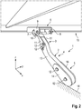
- Fig. 2 is a partial view of the attachment 15, here a cutter, shown from below with a sensing bracket 1 arranged thereon.
- the attachment 15 is shown in a position in which the feeler bar 1 rests at least with its lower section 5 on the floor 16. As can be seen from the illustration, the feeler bar 1 is deflected in the direction of the base 16 due to the prestress by the respective leg spring 10. If the attachment 15 is at its set cutting height, the feeler bar 1 is pressed against the ground. This avoids that the feeler bar 1 is raised or starts to jump when driving over stubble.
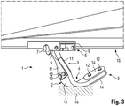
- FIG. 3 shows a partial view of the front attachment 15 from below with the tactile bracket 1 folded over to the side.
- the intermediate section 4 has great flexibility, which enables the harvesting machine to reverse or turn a corner, reversibly laterally, ie in the transverse direction y to flip or swing away. In this way, the feeler bar 1 can be protected from damage.
- the quality of the distance measurement is prevented from being influenced by jumping or bending of the sensing bracket 1 in the vertical direction z due to the high geometrical moment of inertia.
Landscapes
- Life Sciences & Earth Sciences (AREA)
- Environmental Sciences (AREA)
- Harvester Elements (AREA)
- Harvesting Machines For Root Crops (AREA)
Abstract
Description
- Die vorliegende Erfindung betrifft einen Tastbügel für ein Vorsatzgerät, insbesondere ein Schneidwerk, wobei der Tastbügel einen länglichen Körper aufweist, wobei an einem Ende des länglichen Körpers eine quer zur Längsachse verlaufende Aufnahme zur Durchführung einer Welle angeordnet ist, um die der Tastbügel schwenkbar ist, und wobei ein gegenüberliegendes freies Ende zur Abtastung über einen Boden führbar ist.
- Vorsatzgeräte werden von einer landwirtschaftlichen Erntemaschine getragen und angetrieben über ein abzuerntendes Feld geführt, um Erntegut abzuschneiden und der Erntemaschine zur weiteren Verarbeitung zuzuführen. Dabei ist es erforderlich den Abstand zwischen dem Vorsatzgerät und dem Feldboden möglichst konstant zu halten, um eine einheitliche Schnitthöhe zu erzielen. Zur Detektion des Abstands zwischen dem Vorsatzgerät und dem Feldboden fortlaufend zu bestimmen, ist es bekannt, starre Tastbügel an dem Vorsatzgerät anzuordnen. Die Tastbügel weisen einen länglichen Körper auf, wobei an einem Ende des länglichen Körpers eine quer zur Längsachse verlaufende Aufnahme zur Durchführung einer Welle angeordnet ist, um die der Tastbügel schwenkbar ist, während ein gegenüberliegendes, freies Ende des Körpers zur Abtastung über einen Boden führbar ist. Mittels eines Sensors, beispielsweise eines Drehpotentiometers, wird die Schwenkbewegung des Tastbügels erfasst, um den Abstand zu bestimmen. Um das freie Ende gegen den Feldboden zu drücken, ist der Körper im Anlenkpunkt federbelastet. Das freie Ende des Tastbügels ist bogenförmig ausgeführt, um einem Einstechen in den Feldboden bei einer Rückwärtsfahrt der Erntemaschine zu begegnen. Zur Begrenzung des Schwenkwinkels und zum Schutz des Tastbügels kommt eine Kette zum Einsatz, die einerseits am freien Ende des Tastbügels und andererseits am Rahmen des Vorsatzgerätes befestigt ist. Die Kette ist insofern nachteilig, als sich an dieser Halmgut aufhängen kann, was den Ausfall der Bodenführungsfunktion sowie die Beschädigung des Tastbügels oder des Sensors zur Folge haben kann. Zudem können die Bogenform des freien Endes und die Kette nicht immer verhindern, dass es beim Rückwärtsfahren oder einer engen Kurvenfahrt zu einer Beschädigung eines der Tastbügel kommt.
- Aus der
EP 2 865 257 A1 ist ein Tastbügel der eingangs genannten Art bekannt, welcher einen länglichen Körper aufweist, der aus einer Vielzahl von Schaftelementen besteht, wobei benachbarte Schaftelemente um eine quer zur Längsachse des Körpers verlaufende Achse schwenkbar miteinander verbunden sind. Um die Schaftelemente in einer vorgebbaren Betriebsposition zu halten, ist ein Kabel vorgesehen, auf welchem die Schaftelemente hintereinander aufgereiht aufgezogen sind. Ein solcher Tastbügel weist einen sehr komplexen Aufbau auf, wodurch dieser in der Herstellung aufwendig ist. Zudem kann sich zwischen den einzelnen Schaftelementen Halmgut festsetzen, wodurch die Funktionalität des Tastbügels beeinflusst negativ wird. - Der vorliegenden Erfindung liegt die Aufgabe zugrunde, einen Tastbügel der eingangs genannten Art derart weiterzubilden, dass die eingangs genannten Nachteile vermieden werden, insbesondere, dass sich der Tastbügel durch einen einfacheren Aufbau auszeichnet.
- Diese Aufgabe wird erfindungsgemäß durch einen Tastbügel mit den Merkmalen des unabhängigen Anspruches 1 gelöst. Vorteilhafte Weiterbildungen sind Gegenstand der abhängigen Unteransprüche.
- Gemäß dem Anspruch 1 wird ein Tastbügel für ein Vorsatzgerät, insbesondere ein Schneidwerk, vorgeschlagen, wobei der durch eine Federkraft belastete Tastbügel einen länglichen Körper aufweist, wobei an einem Ende des länglichen Körpers eine quer zur Längsachse verlaufende Aufnahme zur Durchführung einer Welle angeordnet ist, um die der Tastbügel schwenkbar ist, und wobei ein gegenüberliegendes freies Ende zur Abtastung über einen Boden führbar ist. Erfindungsgemäß ist vorgesehen, dass der Körper in zumindest drei Abschnitte unterteilt ist, wobei ein oberer Abschnitt, an dem die Aufnahme angeordnet ist, und ein unterer Abschnitt, der das freie, den Boden abtastende Ende des Tastbügels bildet, starr ausgeführt sind und ein Zwischenabschnitt, der zwischen dem oberen Abschnitt und dem unteren Abschnitt angeordnet ist und diese miteinander verbindet, flexibel ausgeführt ist. Dabei wird auf die Anbringung einer Kette am dritten Abschnitt verzichtet, sodass die Problematik der Aufnahme von Halmgut vermieden wird. Die Abschnitte des Körpers sind so ausgeführt, dass der Tastbügel in Hochrichtung, in welcher die Federkraft auf den Körper einwirkt, hinreichend starr ist, um ein Durchbiegen aufgrund der Federkraft zu verhindern. Andererseits ermöglicht der Zwischenabschnitt durch seine flexible Ausführung, dass bei einer Rückwärtsfahrt oder bei einer Kurvenfahrt ein reversibles seitliches Wegschwenken oder Umklappen um eine in Hochrichtung verlaufende Achse möglich ist. Hierdurch lässt sich der Tastbügel vor Beschädigungen bewahren. Andererseits wird eine Beeinflussung der Qualität der Abstandsmessung durch Springen oder Durchbiegen des Tastbügels verhindert.
- Hierzu kann der Zwischenabschnitt in Hochrichtung des Körpers eine größere Ausdehnung aufweisen als in Querrichtung. Mit Längsrichtung ist eine entlang einer Längsachse des Körpers verlaufende Erstreckung bezeichnet. Der Körper weist in Längsrichtung eine Längsausdehnung auf. Mit Querrichtung ist eine senkrecht zur Längsachse des Körpers verlaufende Erstreckung bezeichnet. Der Körper weist in Querrichtung eine Breitenausdehnung auf. Mit Hochrichtung ist eine senkrecht zur Längsachse des Körpers verlaufende Erstreckung bezeichnet, welche senkrecht zur Ebene von Längs- und Querrichtung verläuft. Der Zwischenabschnitt weist aufgrund der größeren Ausdehnung in Hochrichtung als in Querrichtung ein hohes Flächenträgheitsmoment auf, wodurch die für das Abtasten des Bodens notwendige Steifigkeit erreicht wird.
- Bevorzugt kann der obere Abschnitt an einem im Wesentlichen U-förmigen Profilbauteil angeordnet sein, mit welchem der obere Abschnitt durch die Welle schwenkbar verbunden ist. Das im Wesentlichen U-förmige Profilbauteil kann die Aufnahme der Welle bilden. Zueinander parallel verlaufende Schenkel des Profilbauteils können koaxial angeordnete Durchgangsbohrungen aufweisen, in welchen die Welle drehbar gelagert ist. Die Welle ist mit einem Sensor zur Erfassung einer Drehbewegung, insbesondere einem Drehpotentiometer, verbunden. Durch den Sensor lässt sich die Auslenkung des Tastbügels bestimmen, so dass auf den Abstand zum Boden geschlossen werden kann.
- Vorzugsweise kann auf der Welle eine Schenkelfeder angeordnet sein, wobei sich ein Schenkel der Schenkelfeder an dem Profilbauteil und ein anderer Schenkel der Schenkelfeder an dem oberen Abschnitt abstützt. Die Anordnung der Schenkelfeder in dem im Wesentlichen U-förmigen Profilbauteil ist bauraumsparend und schützt die Schenkelfeder vor Verschmutzungen. Mittels der Schenkelfeder wird der Tastbügel mit einer Vorspannung beaufschlagt, welche den Tastbügel gegen den Boden drückt. Hierdurch wird vermieden, dass der Tastbügel beim Überfahren von Stoppeln angehoben wird bzw. beginnt zu springen.
- Weiterhin kann an dem Profilbauteil ein Anschlag angeordnet sein, welcher die Schwenkbewegung des Tastbügels begrenzt. Der Anschlag an dem Profilbauteil übernimmt dabei die Funktion der Kette, ohne deren eingangs erwähnten Nachteile aufzuweisen.
- Insbesondere können der obere Abschnitt und der untere Abschnitt jeweils zumindest ein längliches Profilelement umfassen, an welchen der Zwischenabschnitt befestigt ist. Das jeweilige Profilelement des oberen Abschnitts und des unteren Abschnitts des Körpers ist mit dem Zwischenelement vorzugsweise lösbar verbunden. Hierzu kann jeweils zumindest eine Schraubverbindung vorgesehen sein.
- Vorzugsweise können der obere Abschnitt und der untere Abschnitt jeweils zwei parallel zueinander angeordnete Profilelemente umfassen, zwischen denen der Zwischenabschnitt abschnittsweise angeordnet ist. Die jeweils paarweise angeordneten Profilelemente erstrecken sich abschnittsweise in Längsrichtung des Körpers, wodurch dieser versteift wird, so dass sich der starre obere Abschnitt und der ebenfalls starre untere Abschnitt ausbilden können. Die Profilelemente bestehen bevorzugt aus einem Metall.
- Insbesondere kann der Zwischenabschnitt als ein Bauteil aus einem elastischen Material ausgeführt sein. Bevorzugt kann das Bauteil aus einem Kunststoff bestehen. Besonders bevorzugt wird als Material zur Herstellung des Bauteils ein Elastomer verwendet, beispielsweise auf Polyurethanbasis.
- Hierzu sind die Profilelemente des oberen Abschnittes und des unteren Abschnittes bevorzugt aus einem Metall hergestellt. Die insbesondere plattenförmigen Profilelemente können miteinander verschraubt werden. Dabei nehmen die plattenförmigen Profilelemente das den Zwischenabschnitt bildende Bauteil abschnittsweise zwischen sich auf.
- Weiterhin kann sich das den Zwischenabschnitt bildende Bauteil ausgehend vom oberen Abschnitt bis zum unteren Abschnitt im Wesentlichen durchgehend in Längsrichtung des Körpers erstrecken.
- Des Weiteren betrifft die vorliegende Erfindung ein Vorsatzgerät für eine landwirtschaftliche Erntemaschine, welches dadurch gekennzeichnet ist, dass an dem Vorsatzgerät zumindest ein Tastbügel gemäß einem der Ansprüche 1 bis 10 angeordnet ist.
- Die vorliegende Erfindung wird nachstehend anhand eines in den Zeichnungen dargestellten Ausführungsbeispieles näher erläutert.
- Es zeigen:
- Fig. 1
- eine schematische Darstellung eines Tastbügels in perspektivischer Ansicht;
- Fig. 2
- eine Teilansicht eines Vorsatzgerätes von unten mit daran angeordneten Tastbügeln;
- Fig. 3
- eine Teilansicht eines Vorsatzgerätes von unten mit umgeklapptem Tastbügel.
- Für die Ernte von, insbesondere stängeligem, Erntegut kommen selbstfahrende Erntemaschinen wie Mähdrescher zum Einsatz, welche mit einem Vorsatzgerät 15 zum Abtrennen und zur Aufnahme des Erntegutes ausgestattet sind. Zur optimalen Aufnahme des Ernteguts ist das Vorsatzgerät 15, welches insbesondere als ein Schneidwerk ausgeführt sein kann, beweglich ausgeführt, indem das Vorsatzgerät 15 in seiner Höhe wie auch in seiner Querneigung geführt wird. Die vertikale Höhenverstellung, das heißt der Längsneigungsausgleich in Fahrtrichtung wie auch die Veränderung der Querneigung des Vorsatzgerätes 15, erfolgen in Abhängigkeit von dem aktuellen Bodenniveau und dienen damit einer gleichmäßigen Stoppelhöhe des abgeernteten Ernteguts. Zur Bestimmung des Abstands zwischen dem Vorsatzgerät 15 und dem Boden 16 sind an der Unterseite des Vorsatzgerätes 15, d.h. der dem Boden 16 zugewandten Seite, mehrere Tastbügel 1 beabstandet zueinander angeordnet.
- Die Darstellung in
Fig. 1 zeigt eine schematische Darstellung des Tastbügels 1 in perspektivischer Ansicht. Der Tastbügel 1 weist einen länglichen Körper 2 auf, wobei an einem Ende des länglichen Körpers 2 eine quer zur Längsachse 8 verlaufende Aufnahme zur Durchführung einer Welle 7 angeordnet ist. Die Aufnahme ist als ein im Wesentlichen U-förmiges Profilbauteil 6 ausgeführt. Gegenüber dem U-förmigen Profilbauteil 6 ist der Tastbügel 1 relativ schwenkbar. Mittels des Profilbauteils 6 ist der längliche Körper 2 des Tastbügels 1 endseitig an der Unterseite des Vorsatzgerätes 15 angeordnet. Die Welle 7 ist in dem Profilbauteil 6 gelagert. Ein gegenüberliegendes freies Ende des Körpers 2 des Tastbügels 1 ist zur Abtastung über den Boden führbar. - Der Körper 2 ist in zumindest drei Abschnitte 3, 4, 5 unterteilt ist, wobei ein oberer Abschnitt 3, an dem die als Profilbauteil 6 ausgeführte Aufnahme zur Durchführung der Welle 7 angeordnet ist, und ein unterer Abschnitt 5, der das freie, den Boden 16 abtastende Ende des Tastbügels 1 bildet, starr ausgeführt sind. Ein Zwischenabschnitt 4, der zwischen dem oberen Abschnitt 3 und dem unteren Abschnitt 5 angeordnet ist und diese miteinander verbindet, ist flexibel ausgeführt.
- Mit Längsrichtung x ist eine entlang der Längsachse 8 des Körpers 2 verlaufende Erstreckung bezeichnet. Der Körper 2 weist in Längsrichtung x eine Längsausdehnung auf. Mit Querrichtung y ist eine senkrecht zur Längsachse 8 des Körpers 2 verlaufende Erstreckung bezeichnet. Der Körper 2 weist in Querrichtung y eine Breitenausdehnung auf. Mit Hochrichtung z ist eine senkrecht zur Längsachse 8 des Körpers 2 verlaufende Erstreckung bezeichnet, welche senkrecht zur Ebene von Längsrichtung x und Querrichtung y verläuft. Der Zwischenabschnitt 4 weist in Hochrichtung z des Körpers 2 eine größere Ausdehnung auf als in Querrichtung y des Körpers 2. Der Zwischenabschnitt 4 weist aufgrund der größeren Ausdehnung in Hochrichtung z als in Querrichtung y ein hohes Flächenträgheitsmoment auf, wodurch die für das Abtasten des Bodens 16 notwendige Steifigkeit des Tastbügels 1 erreicht wird. Der Zwischenabschnitt 4 ist als ein Bauteil 13 aus einem elastischen Material ausgeführt. Bevorzugt besteht das Bauteil 13 aus einem Elastomer.
- Zueinander parallel verlaufende Schenkel 9 des Profilbauteils 6 weisen koaxial angeordnete Durchgangsbohrungen auf, in welchen die Welle 7 drehbar gelagert ist. Die Welle 7 ist mit einem - nicht dargestellten - Sensor zur Erfassung einer Drehbewegung, insbesondere einem Drehpotentiometer, verbunden. Durch den Sensor lässt sich die Auslenkung des Tastbügels 1 bestimmen, die durch eine Bodenunebenheit hervorgerufen wird.
- Der obere Abschnitt 3 des Tastbügels 1 umfasst zwei parallel zueinander angeordnete Profilelemente 11, zwischen denen der Zwischenabschnitt 4 abschnittsweise angeordnet ist. Die Profilelemente 11 sind plattenförmig ausgeführt. Insbesondere können die Profilelemente 11 als Stanzbauteile ausgeführt sein. Das Bauteil 13, welches den Zwischenabschnitt 4 ausbildet, ist durch Schraubverbindungen 12 mit den Profilelementen 11 lösbar verbunden. Auf diese Weise lässt sich ein einfacher Austausch zumindest des Zwischenabschnitts 4 durchführen.
- Der untere Abschnitt 5 des Tastbügels 1 umfasst ebenfalls zwei parallel zueinander angeordnete Profilelemente 14, zwischen denen der Zwischenabschnitt 4 abschnittsweise angeordnet ist. Auch diese Profilelemente 14 sind durch Schraubverbindungen 12 mit dem Bauteil 13 lösbar verbunden. Die Profilelemente 14 sind im Wesentlichen plattenförmig ausgeführt. Insbesondere können die Profilelemente 14 als Stanzbauteile ausgeführt sein.
- Die Profilelemente 11 und 14 dienen dazu, das Bauteil 13, welches den Zwischenabschnitt 4 ausbildet, im oberen Abschnitt 3 und im unteren Abschnitt 5 zu versteifen sowie insbesondere im unteren Abschnitt 5 vor Verschleiß zu schützen. Hierzu bestehen die Profilelemente 11 und 14 aus einem Metall.
- Der Tastbügel 1 wird mit einer Federkraft beaufschlagt, um einen stetigen Kontakt mit dem zu kopierenden Boden 16 aufrechtzuerhalten. Hierzu ist an der Welle 7 eine Schenkelfeder 10 angeordnet. Ein Schenkel der Schenkelfeder 10 stützt sich an dem Profilbauteil 6 ab und ein anderer Schenkel der Schenkelfeder 10 stützt sich an dem oberen Abschnitt 3 ab. Die Anordnung der Schenkelfeder 10 in dem im Wesentlichen U-förmigen Profilbauteil ist bauraumsparend und schützt die Schenkelfeder 10 vor Verschmutzungen. Mittels der Schenkelfeder 10 wird der Tastbügel 1 mit einer Vorspannung beaufschlagt, welche den Tastbügel 1 gegen den Boden 16 drückt. Hierdurch wird vermieden, dass der Tastbügel 1 beim Überfahren von Stoppeln angehoben wird bzw. beginnt zu springen. Durch die Versteifung des Bauteils 13 einerseits und das erhöhte Flächenträgheitsmoment des Bauteils 13 im Zwischenabschnitt 4 andererseits wird ein Durchbiegen aufgrund der Vorspannung durch die Schenkelfeder 10 vermieden.
- In
Fig. 2 ist eine Teilansicht des Vorsatzgerätes 15, hier eines Schneidwerks, von unten mit einem daran angeordneten Tastbügel 1 dargestellt. Das Vorsatzgerät 15 ist dabei in einer Position dargestellt, in welcher der Tastbügel 1 zumindest mit seinem unteren Abschnitt 5 auf dem Boden 16 aufliegt. Wie aus der Darstellung ersichtlich ist, ist der Tastbügel 1 aufgrund der Vorspannung durch die jeweilige Schenkelfeder 10 in Richtung des Bodens 16 ausgelenkt. Befindet sich das Vorsatzgerät 15 auf seiner eingestellten Schnitthöhe, so wird der Tastbügel 1 gegen den Boden gedrückt. Hierdurch wird vermieden, dass der Tastbügel 1 beim Überfahren von Stoppeln angehoben wird bzw. beginnt zu springen. - Die Darstellung in
Fig. 3 zeigt eine Teilansicht des Vorsatzgerätes 15 von unten mit seitlich umgeklapptem Tastbügel 1. Durch die Ausführung des Bauteils 13 aus einem Elastomer weist der Zwischenabschnitt 4 eine große Flexibilität auf, welche es bei einer Rückwärtsfahrt oder einer Kurvenfahrt der Erntemaschine ermöglicht, reversibel seitlich, d.h. in Querrichtung y, umzuklappen oder wegzuschwenken. Hierdurch lässt sich der Tastbügel 1 vor Beschädigungen bewahren. Andererseits wird eine Beeinflussung der Qualität der Abstandsmessung durch Springen oder Durchbiegen des Tastbügels 1 in Hochrichtung z aufgrund des hohen Flächenträgheitsmomentes verhindert. -
- 1
- Tastbügel
- 2
- Körper
- 3
- Oberer Abschnitt
- 4
- Zwischenabschnitt
- 5
- Unterer Abschnitt
- 6
- Profilbauteil
- 7
- Welle
- 8
- Längsachse von 1
- 9
- Schenkel
- 10
- Schenkelfeder
- 11
- Profilelement
- 12
- Schraubverbindung
- 13
- Bauteil
- 14
- Profilelement
- 15
- Vorsatzgerät
- 16
- Boden
Claims (11)
- Tastbügel (1) für ein Vorsatzgerät (15), insbesondere ein Schneidwerk, wobei der durch eine Federkraft belastete Tastbügel (1) einen länglichen Körper (2) aufweist, wobei an einem Ende des länglichen Körpers (2) eine quer zur Längsachse (8) verlaufende Aufnahme zur Durchführung einer Welle (7) angeordnet ist, um die der Tastbügel (1) schwenkbar ist, und wobei ein gegenüberliegendes freies Ende des Tastbügels (1) zur Abtastung über einen Boden (16) führbar ist, dadurch gekennzeichnet, dass der Körper (2) in zumindest drei Abschnitte unterteilt ist, wobei ein oberer Abschnitt (3), an dem die Aufnahme angeordnet ist, und ein unterer Abschnitt (5), der das freie, den Boden (16) abtastende Ende des Tastbügels (1) bildet, starr ausgeführt sind und ein Zwischenabschnitt (4), der zwischen dem oberen Abschnitt (3) und dem unteren Abschnitt (5) angeordnet ist und diese miteinander verbindet, flexibel ausgeführt ist.
- Tastbügel (1) nach Anspruch 1, dadurch gekennzeichnet, dass der Zwischenabschnitt (4) in Hochrichtung (z) des Körpers (2) eine größere Ausdehnung aufweist als in Querrichtung (y).
- Tastbügel (1) nach Anspruch 1 oder 2, dadurch gekennzeichnet, dass der obere Abschnitt (3) an einem im Wesentlichen U-förmigen Profilbauteil (6) angeordnet ist, mit welchem der obere Abschnitt (3) durch die Welle (7) schwenkbar verbunden.
- Tastbügel (1) nach Anspruch 3, dadurch gekennzeichnet, dass auf der Welle (7) eine Schenkelfeder (10) angeordnet ist, wobei sich ein Schenkel der Schenkelfeder (10) an dem Profilbauteil (6) und ein anderer Schenkel der Schenkelfeder (10) an dem oberen Abschnitt (3) abstützt.
- Tastbügel (1) nach Anspruch 3 oder 4, dadurch gekennzeichnet, dass an dem Profilbauteil (6) ein Anschlag angeordnet ist, welcher die Schwenkbewegung des Tastbügels (1) begrenzt.
- Tastbügel (1) nach Anspruch einem der Ansprüche 1 bis 5, dadurch gekennzeichnet, dass der obere Abschnitt (3) und der untere Abschnitt (5) jeweils zumindest ein längliches Profilelement (11, 14) umfassen, an welchen der Zwischenabschnitt (4) befestigt ist.
- Tastbügel (1) nach Anspruch 6, dadurch gekennzeichnet, dass der obere Abschnitt (3) und der untere Abschnitt (5) jeweils zwei parallel zueinander angeordnete Profilelemente (11, 14) umfassen, zwischen denen der Zwischenabschnitt (4) abschnittsweise angeordnet ist.
- Tastbügel (1) nach einem der Ansprüche 1 bis 7, dadurch gekennzeichnet, dass der Zwischenabschnitt (4) als ein Bauteil (13) aus einem elastischen Material ausgeführt ist.
- Tastbügel (1) nach einem der vorangehenden Ansprüche, dadurch gekennzeichnet, dass die Profilelemente (11, 14) des oberen Abschnittes (3) und des unteren Abschnittes (5) aus einem Metall hergestellt sind.
- Tastbügel (1) nach einem der vorangehenden Ansprüche, dadurch gekennzeichnet, dass sich das den Zwischenabschnitt (4) bildende Bauteil (13) ausgehend vom oberen Abschnitt (3) bis zum unteren Abschnitt (4) im Wesentlichen durchgehend in Längsrichtung des Körpers (2) erstreckt.
- Vorsatzgerät (15) für eine landwirtschaftliche Erntemaschine, dadurch gekennzeichnet, dass an dem Vorsatzgerät (15) zumindest ein Tastbügel (1) gemäß einem der Ansprüche 1 bis 10 angeordnet ist.
Applications Claiming Priority (1)
| Application Number | Priority Date | Filing Date | Title |
|---|---|---|---|
| DE102019107376.6A DE102019107376A1 (de) | 2019-03-22 | 2019-03-22 | Tastbügel |
Publications (2)
| Publication Number | Publication Date |
|---|---|
| EP3711472A1 true EP3711472A1 (de) | 2020-09-23 |
| EP3711472B1 EP3711472B1 (de) | 2021-11-17 |
Family
ID=68806684
Family Applications (1)
| Application Number | Title | Priority Date | Filing Date |
|---|---|---|---|
| EP19213858.4A Active EP3711472B1 (de) | 2019-03-22 | 2019-12-05 | Tastbügel |
Country Status (2)
| Country | Link |
|---|---|
| EP (1) | EP3711472B1 (de) |
| DE (1) | DE102019107376A1 (de) |
Cited By (1)
| Publication number | Priority date | Publication date | Assignee | Title |
|---|---|---|---|---|
| US20240224850A1 (en) * | 2023-01-09 | 2024-07-11 | Cnh Industrial America Llc | Breakaway rigid header height control system |
Citations (5)
| Publication number | Priority date | Publication date | Assignee | Title |
|---|---|---|---|---|
| US3611286A (en) * | 1970-03-20 | 1971-10-05 | Arthur B Cleveland | Device for sensing the position of a moving vehicle with respect to a furrow |
| US6202395B1 (en) * | 1997-12-31 | 2001-03-20 | Richard Gramm | Combine header height control |
| CA2511418A1 (en) * | 2004-07-29 | 2006-01-29 | Richard Gramm | Height sensor arrangement for agricultural applications |
| EP2865257A1 (de) | 2013-10-22 | 2015-04-29 | Deere & Company | Höhenfühler für Erntekopf |
| EP3360406A1 (de) * | 2017-02-10 | 2018-08-15 | CNH Industrial Belgium NV | Bodenhöhenmessvorrichtung |
-
2019
- 2019-03-22 DE DE102019107376.6A patent/DE102019107376A1/de active Pending
- 2019-12-05 EP EP19213858.4A patent/EP3711472B1/de active Active
Patent Citations (5)
| Publication number | Priority date | Publication date | Assignee | Title |
|---|---|---|---|---|
| US3611286A (en) * | 1970-03-20 | 1971-10-05 | Arthur B Cleveland | Device for sensing the position of a moving vehicle with respect to a furrow |
| US6202395B1 (en) * | 1997-12-31 | 2001-03-20 | Richard Gramm | Combine header height control |
| CA2511418A1 (en) * | 2004-07-29 | 2006-01-29 | Richard Gramm | Height sensor arrangement for agricultural applications |
| EP2865257A1 (de) | 2013-10-22 | 2015-04-29 | Deere & Company | Höhenfühler für Erntekopf |
| EP3360406A1 (de) * | 2017-02-10 | 2018-08-15 | CNH Industrial Belgium NV | Bodenhöhenmessvorrichtung |
Cited By (2)
| Publication number | Priority date | Publication date | Assignee | Title |
|---|---|---|---|---|
| US20240224850A1 (en) * | 2023-01-09 | 2024-07-11 | Cnh Industrial America Llc | Breakaway rigid header height control system |
| US12484474B2 (en) * | 2023-01-09 | 2025-12-02 | Cnh Industrial America Llc | Breakaway rigid header height control system |
Also Published As
| Publication number | Publication date |
|---|---|
| DE102019107376A1 (de) | 2020-09-24 |
| EP3711472B1 (de) | 2021-11-17 |
Similar Documents
| Publication | Publication Date | Title |
|---|---|---|
| EP2754346B1 (de) | Schneidwerk | |
| EP1880591B1 (de) | Kartoffelerntemaschine | |
| DE2556688C2 (de) | Vorrichtung zum Aufnehmen und Weiterbefördern von Erntegut, insbesondere Getreide auf einer Erntemaschine, insbesondere einem Mähdrescher | |
| DE102012108835A1 (de) | Schneidwerk | |
| DE102010037131A1 (de) | Schneidwerk | |
| DD156889A5 (de) | Vorrichtung zum verteilen von siebgut | |
| EP2915421B1 (de) | Stoppelknicker für einen maispflücker | |
| DE2807250A1 (de) | Vorrichtung zum fuehren einer erntemaschine entlang von pflanzenreihen | |
| EP0713639B1 (de) | Tastvorrichtung zur selbsttätigen Seitenführung einer selbstfahrenden Erntemaschine | |
| DE3407333C2 (de) | ||
| EP2238822B1 (de) | Mähfingeranordnung | |
| DE202008004736U1 (de) | Striegelzinkenform und/oder -lagerung | |
| DE2815936C2 (de) | ||
| DE102018105858A1 (de) | Vorsatzgerät eines landwirtschaftlichen Erntefahrzeugs und landwirtschaftliches Erntefahrzeug | |
| DE10123248C1 (de) | Ährenheber für Erntemaschinenmähsysteme | |
| EP3711472B1 (de) | Tastbügel | |
| EP2959765A1 (de) | Schneidwerk mit mittelteil und seitlich dazu angeordneten seitenteilen | |
| DE3035606C2 (de) | Kreiselegge | |
| WO2016198279A1 (de) | Tragschiene eines ährenhebers für erntegut | |
| EP3017683A1 (de) | Bandrechen | |
| EP4543184A1 (de) | Pick-up-vorsatzgerät für eine erntemaschine | |
| DE102004058116A1 (de) | Erntemaschine | |
| DE10058017A1 (de) | Kraftfahrzeugsitz | |
| DE102005040133A1 (de) | Grubber | |
| DE10209722A1 (de) | Verfahren und Vorrichtung zur Verstellung von Führungsblechen |
Legal Events
| Date | Code | Title | Description |
|---|---|---|---|
| PUAI | Public reference made under article 153(3) epc to a published international application that has entered the european phase |
Free format text: ORIGINAL CODE: 0009012 |
|
| STAA | Information on the status of an ep patent application or granted ep patent |
Free format text: STATUS: THE APPLICATION HAS BEEN PUBLISHED |
|
| AK | Designated contracting states |
Kind code of ref document: A1 Designated state(s): AL AT BE BG CH CY CZ DE DK EE ES FI FR GB GR HR HU IE IS IT LI LT LU LV MC MK MT NL NO PL PT RO RS SE SI SK SM TR |
|
| AX | Request for extension of the european patent |
Extension state: BA ME |
|
| STAA | Information on the status of an ep patent application or granted ep patent |
Free format text: STATUS: REQUEST FOR EXAMINATION WAS MADE |
|
| 17P | Request for examination filed |
Effective date: 20210323 |
|
| RBV | Designated contracting states (corrected) |
Designated state(s): AL AT BE BG CH CY CZ DE DK EE ES FI FR GB GR HR HU IE IS IT LI LT LU LV MC MK MT NL NO PL PT RO RS SE SI SK SM TR |
|
| GRAP | Despatch of communication of intention to grant a patent |
Free format text: ORIGINAL CODE: EPIDOSNIGR1 |
|
| STAA | Information on the status of an ep patent application or granted ep patent |
Free format text: STATUS: GRANT OF PATENT IS INTENDED |
|
| INTG | Intention to grant announced |
Effective date: 20210708 |
|
| GRAS | Grant fee paid |
Free format text: ORIGINAL CODE: EPIDOSNIGR3 |
|
| GRAA | (expected) grant |
Free format text: ORIGINAL CODE: 0009210 |
|
| STAA | Information on the status of an ep patent application or granted ep patent |
Free format text: STATUS: THE PATENT HAS BEEN GRANTED |
|
| AK | Designated contracting states |
Kind code of ref document: B1 Designated state(s): AL AT BE BG CH CY CZ DE DK EE ES FI FR GB GR HR HU IE IS IT LI LT LU LV MC MK MT NL NO PL PT RO RS SE SI SK SM TR |
|
| REG | Reference to a national code |
Ref country code: GB Ref legal event code: FG4D Free format text: NOT ENGLISH |
|
| REG | Reference to a national code |
Ref country code: IE Ref legal event code: FG4D Free format text: LANGUAGE OF EP DOCUMENT: GERMAN |
|
| REG | Reference to a national code |
Ref country code: DE Ref legal event code: R096 Ref document number: 502019002773 Country of ref document: DE |
|
| REG | Reference to a national code |
Ref country code: AT Ref legal event code: REF Ref document number: 1447293 Country of ref document: AT Kind code of ref document: T Effective date: 20211215 |
|
| REG | Reference to a national code |
Ref country code: LT Ref legal event code: MG9D |
|
| REG | Reference to a national code |
Ref country code: NL Ref legal event code: MP Effective date: 20211117 |
|
| PG25 | Lapsed in a contracting state [announced via postgrant information from national office to epo] |
Ref country code: RS Free format text: LAPSE BECAUSE OF FAILURE TO SUBMIT A TRANSLATION OF THE DESCRIPTION OR TO PAY THE FEE WITHIN THE PRESCRIBED TIME-LIMIT Effective date: 20211117 Ref country code: LT Free format text: LAPSE BECAUSE OF FAILURE TO SUBMIT A TRANSLATION OF THE DESCRIPTION OR TO PAY THE FEE WITHIN THE PRESCRIBED TIME-LIMIT Effective date: 20211117 Ref country code: FI Free format text: LAPSE BECAUSE OF FAILURE TO SUBMIT A TRANSLATION OF THE DESCRIPTION OR TO PAY THE FEE WITHIN THE PRESCRIBED TIME-LIMIT Effective date: 20211117 Ref country code: BG Free format text: LAPSE BECAUSE OF FAILURE TO SUBMIT A TRANSLATION OF THE DESCRIPTION OR TO PAY THE FEE WITHIN THE PRESCRIBED TIME-LIMIT Effective date: 20220217 |
|
| PG25 | Lapsed in a contracting state [announced via postgrant information from national office to epo] |
Ref country code: IS Free format text: LAPSE BECAUSE OF FAILURE TO SUBMIT A TRANSLATION OF THE DESCRIPTION OR TO PAY THE FEE WITHIN THE PRESCRIBED TIME-LIMIT Effective date: 20220317 Ref country code: SE Free format text: LAPSE BECAUSE OF FAILURE TO SUBMIT A TRANSLATION OF THE DESCRIPTION OR TO PAY THE FEE WITHIN THE PRESCRIBED TIME-LIMIT Effective date: 20211117 Ref country code: PT Free format text: LAPSE BECAUSE OF FAILURE TO SUBMIT A TRANSLATION OF THE DESCRIPTION OR TO PAY THE FEE WITHIN THE PRESCRIBED TIME-LIMIT Effective date: 20220317 Ref country code: PL Free format text: LAPSE BECAUSE OF FAILURE TO SUBMIT A TRANSLATION OF THE DESCRIPTION OR TO PAY THE FEE WITHIN THE PRESCRIBED TIME-LIMIT Effective date: 20211117 Ref country code: NO Free format text: LAPSE BECAUSE OF FAILURE TO SUBMIT A TRANSLATION OF THE DESCRIPTION OR TO PAY THE FEE WITHIN THE PRESCRIBED TIME-LIMIT Effective date: 20220217 Ref country code: NL Free format text: LAPSE BECAUSE OF FAILURE TO SUBMIT A TRANSLATION OF THE DESCRIPTION OR TO PAY THE FEE WITHIN THE PRESCRIBED TIME-LIMIT Effective date: 20211117 Ref country code: LV Free format text: LAPSE BECAUSE OF FAILURE TO SUBMIT A TRANSLATION OF THE DESCRIPTION OR TO PAY THE FEE WITHIN THE PRESCRIBED TIME-LIMIT Effective date: 20211117 Ref country code: HR Free format text: LAPSE BECAUSE OF FAILURE TO SUBMIT A TRANSLATION OF THE DESCRIPTION OR TO PAY THE FEE WITHIN THE PRESCRIBED TIME-LIMIT Effective date: 20211117 Ref country code: GR Free format text: LAPSE BECAUSE OF FAILURE TO SUBMIT A TRANSLATION OF THE DESCRIPTION OR TO PAY THE FEE WITHIN THE PRESCRIBED TIME-LIMIT Effective date: 20220218 |
|
| PG25 | Lapsed in a contracting state [announced via postgrant information from national office to epo] |
Ref country code: SM Free format text: LAPSE BECAUSE OF FAILURE TO SUBMIT A TRANSLATION OF THE DESCRIPTION OR TO PAY THE FEE WITHIN THE PRESCRIBED TIME-LIMIT Effective date: 20211117 Ref country code: SK Free format text: LAPSE BECAUSE OF FAILURE TO SUBMIT A TRANSLATION OF THE DESCRIPTION OR TO PAY THE FEE WITHIN THE PRESCRIBED TIME-LIMIT Effective date: 20211117 Ref country code: RO Free format text: LAPSE BECAUSE OF FAILURE TO SUBMIT A TRANSLATION OF THE DESCRIPTION OR TO PAY THE FEE WITHIN THE PRESCRIBED TIME-LIMIT Effective date: 20211117 Ref country code: ES Free format text: LAPSE BECAUSE OF FAILURE TO SUBMIT A TRANSLATION OF THE DESCRIPTION OR TO PAY THE FEE WITHIN THE PRESCRIBED TIME-LIMIT Effective date: 20211117 Ref country code: EE Free format text: LAPSE BECAUSE OF FAILURE TO SUBMIT A TRANSLATION OF THE DESCRIPTION OR TO PAY THE FEE WITHIN THE PRESCRIBED TIME-LIMIT Effective date: 20211117 Ref country code: DK Free format text: LAPSE BECAUSE OF FAILURE TO SUBMIT A TRANSLATION OF THE DESCRIPTION OR TO PAY THE FEE WITHIN THE PRESCRIBED TIME-LIMIT Effective date: 20211117 Ref country code: CZ Free format text: LAPSE BECAUSE OF FAILURE TO SUBMIT A TRANSLATION OF THE DESCRIPTION OR TO PAY THE FEE WITHIN THE PRESCRIBED TIME-LIMIT Effective date: 20211117 |
|
| REG | Reference to a national code |
Ref country code: DE Ref legal event code: R097 Ref document number: 502019002773 Country of ref document: DE |
|
| PG25 | Lapsed in a contracting state [announced via postgrant information from national office to epo] |
Ref country code: MC Free format text: LAPSE BECAUSE OF FAILURE TO SUBMIT A TRANSLATION OF THE DESCRIPTION OR TO PAY THE FEE WITHIN THE PRESCRIBED TIME-LIMIT Effective date: 20211117 |
|
| PLBE | No opposition filed within time limit |
Free format text: ORIGINAL CODE: 0009261 |
|
| STAA | Information on the status of an ep patent application or granted ep patent |
Free format text: STATUS: NO OPPOSITION FILED WITHIN TIME LIMIT |
|
| 26N | No opposition filed |
Effective date: 20220818 |
|
| PG25 | Lapsed in a contracting state [announced via postgrant information from national office to epo] |
Ref country code: LU Free format text: LAPSE BECAUSE OF NON-PAYMENT OF DUE FEES Effective date: 20211205 Ref country code: IE Free format text: LAPSE BECAUSE OF NON-PAYMENT OF DUE FEES Effective date: 20211205 Ref country code: AL Free format text: LAPSE BECAUSE OF FAILURE TO SUBMIT A TRANSLATION OF THE DESCRIPTION OR TO PAY THE FEE WITHIN THE PRESCRIBED TIME-LIMIT Effective date: 20211117 |
|
| PG25 | Lapsed in a contracting state [announced via postgrant information from national office to epo] |
Ref country code: SI Free format text: LAPSE BECAUSE OF FAILURE TO SUBMIT A TRANSLATION OF THE DESCRIPTION OR TO PAY THE FEE WITHIN THE PRESCRIBED TIME-LIMIT Effective date: 20211117 Ref country code: FR Free format text: LAPSE BECAUSE OF NON-PAYMENT OF DUE FEES Effective date: 20220117 |
|
| P01 | Opt-out of the competence of the unified patent court (upc) registered |
Effective date: 20230516 |
|
| PG25 | Lapsed in a contracting state [announced via postgrant information from national office to epo] |
Ref country code: CY Free format text: LAPSE BECAUSE OF FAILURE TO SUBMIT A TRANSLATION OF THE DESCRIPTION OR TO PAY THE FEE WITHIN THE PRESCRIBED TIME-LIMIT Effective date: 20211117 |
|
| PG25 | Lapsed in a contracting state [announced via postgrant information from national office to epo] |
Ref country code: HU Free format text: LAPSE BECAUSE OF FAILURE TO SUBMIT A TRANSLATION OF THE DESCRIPTION OR TO PAY THE FEE WITHIN THE PRESCRIBED TIME-LIMIT; INVALID AB INITIO Effective date: 20191205 |
|
| REG | Reference to a national code |
Ref country code: CH Ref legal event code: PL |
|
| PG25 | Lapsed in a contracting state [announced via postgrant information from national office to epo] |
Ref country code: LI Free format text: LAPSE BECAUSE OF NON-PAYMENT OF DUE FEES Effective date: 20221231 Ref country code: CH Free format text: LAPSE BECAUSE OF NON-PAYMENT OF DUE FEES Effective date: 20221231 |
|
| PG25 | Lapsed in a contracting state [announced via postgrant information from national office to epo] |
Ref country code: MK Free format text: LAPSE BECAUSE OF FAILURE TO SUBMIT A TRANSLATION OF THE DESCRIPTION OR TO PAY THE FEE WITHIN THE PRESCRIBED TIME-LIMIT Effective date: 20211117 |
|
| PG25 | Lapsed in a contracting state [announced via postgrant information from national office to epo] |
Ref country code: TR Free format text: LAPSE BECAUSE OF FAILURE TO SUBMIT A TRANSLATION OF THE DESCRIPTION OR TO PAY THE FEE WITHIN THE PRESCRIBED TIME-LIMIT Effective date: 20211117 |
|
| GBPC | Gb: european patent ceased through non-payment of renewal fee |
Effective date: 20231205 |
|
| PG25 | Lapsed in a contracting state [announced via postgrant information from national office to epo] |
Ref country code: MT Free format text: LAPSE BECAUSE OF FAILURE TO SUBMIT A TRANSLATION OF THE DESCRIPTION OR TO PAY THE FEE WITHIN THE PRESCRIBED TIME-LIMIT Effective date: 20211117 |
|
| PG25 | Lapsed in a contracting state [announced via postgrant information from national office to epo] |
Ref country code: GB Free format text: LAPSE BECAUSE OF NON-PAYMENT OF DUE FEES Effective date: 20231205 |
|
| PG25 | Lapsed in a contracting state [announced via postgrant information from national office to epo] |
Ref country code: GB Free format text: LAPSE BECAUSE OF NON-PAYMENT OF DUE FEES Effective date: 20231205 |
|
| PGFP | Annual fee paid to national office [announced via postgrant information from national office to epo] |
Ref country code: DE Payment date: 20251211 Year of fee payment: 7 |
|
| PGFP | Annual fee paid to national office [announced via postgrant information from national office to epo] |
Ref country code: IT Payment date: 20251223 Year of fee payment: 7 |
|
| PGFP | Annual fee paid to national office [announced via postgrant information from national office to epo] |
Ref country code: BE Payment date: 20251219 Year of fee payment: 7 |
|
| REG | Reference to a national code |
Ref country code: AT Ref legal event code: MM01 Ref document number: 1447293 Country of ref document: AT Kind code of ref document: T Effective date: 20241205 |
|
| PG25 | Lapsed in a contracting state [announced via postgrant information from national office to epo] |
Ref country code: AT Free format text: LAPSE BECAUSE OF NON-PAYMENT OF DUE FEES Effective date: 20241205 |
|
| PGFP | Annual fee paid to national office [announced via postgrant information from national office to epo] |
Ref country code: AT Payment date: 20260410 Year of fee payment: 5 |