EP2865257A1 - Height sensor for harvesting head - Google Patents
Height sensor for harvesting head Download PDFInfo
- Publication number
- EP2865257A1 EP2865257A1 EP20140186107 EP14186107A EP2865257A1 EP 2865257 A1 EP2865257 A1 EP 2865257A1 EP 20140186107 EP20140186107 EP 20140186107 EP 14186107 A EP14186107 A EP 14186107A EP 2865257 A1 EP2865257 A1 EP 2865257A1
- Authority
- EP
- European Patent Office
- Prior art keywords
- shaft elements
- sensor
- height sensor
- shaft
- cable
- Prior art date
- Legal status (The legal status is an assumption and is not a legal conclusion. Google has not performed a legal analysis and makes no representation as to the accuracy of the status listed.)
- Withdrawn
Links
Images


Classifications
-
- A—HUMAN NECESSITIES
- A01—AGRICULTURE; FORESTRY; ANIMAL HUSBANDRY; HUNTING; TRAPPING; FISHING
- A01D—HARVESTING; MOWING
- A01D41/00—Combines, i.e. harvesters or mowers combined with threshing devices
- A01D41/12—Details of combines
- A01D41/14—Mowing tables
- A01D41/141—Automatic header control
Definitions
- This invention relates to harvesting heads for agricultural harvesters.
- it relates to height sensors for agricultural harvesting heads.
- Harvesting heads for agricultural harvesters are typically carried over the ground at a predetermined height.
- sensors are often provided to sense the distance between the harvesting head of the ground.
- a rigid arm that drags along the ground.
- the rigid arm is connected to a rotary sensor element at its upper end and drags along the ground at its lower end. As the ground engaging end of the rigid arm is pushed upward by the ground, the upper end of the rigid arm rotates the rotary sensor.
- the coil spring of the previous example is eliminated by providing an elongate sensor arm made of a plastic composite. This solves the problems of contaminants becoming wedged between the coils of the coil spring section, but also provides a sensor arm that is more susceptible to damage.
- the sensor arm is made very elongate, and the distal end (i.e. the ground engaging end) must be chained or cabled to the chassis of the agricultural harvesting head to prevent the sensor arm from flexing forward.
- the point at which it contacts the ground is considerably behind the sensor element itself, and thus it may not sense a precipitous change in the height of the agricultural harvesting head until the forward portions of the agricultural harvesting head have already collided with the ground.
- a spring-loaded reversing joint is provided at the upper end of the arm where it attaches to the sensing element.
- This arrangement permits the arm to be pushed forward at its lower end by flexure/pivoting at the reversing joint.
- This arrangement provides only a single point/joint at which the arm can flex forward, while the rest of the arm remains straight and rigid. Unless sufficient clearance is provided around the sensor arm, the sensor arm can reverse, but cannot flex forward and fold flat enough to completely avoid damaging the sensor arm and/or the sensing element, particularly when the harvesting head is disposed close to the ground.
- a height sensor for an agricultural harvesting head that harvests agricultural crops while traveling in a harvesting direction comprising: a sensor element; a sensor arm, the sensor arm comprising a plurality of shaft elements, wherein each of the plurality of shaft elements is pivotally coupled to an adjacent one of the shaft elements, and wherein the plurality of shaft elements are held in a predefined operating position by a cable, and further wherein the cable extends through the plurality of shaft elements.
- Each of the plurality of shaft elements may define a passageway extending therethrough, and through which the cable extends.
- the cable may be anchored at one end to a lower one of the plurality of shaft elements, is slidingly supported in and extends through a second plurality of the plurality of shaft elements.
- a coil spring may be disposed at an upper end of the sensor arm.
- the cable may have an upper end, and the upper end of the cable (may be coupled to the coil spring.
- the cable may be preloaded to hold the sensor arm into a fixed operating shape.
- the height sensor may further comprise a plurality of pivot pins, wherein each of the plurality of pivot pins pivotally couples said each of the plurality of shaft elements to said an adjacent one of the plurality of shaft elements.
- Each of the plurality of pivot pins may extend perpendicular to the harvesting direction. Each of the plurality of pivot pins may extend in a direction parallel to others of the plurality of pivot pins.
- Each of the plurality of shaft elements may be identically constructed to others of the plurality of shaft elements. An upper end of each of the plurality of shaft elements may be received into a lower end of each of said plurality of shaft elements. The lower end of each of the plurality of shaft elements may be shingled over the upper end of another of each of said plurality of shaft elements.
- a height sensor 100 is shown mounted to a support structure 102.
- the support structure 102 and the height sensor 100 travel through an agricultural field in a direction "V".
- the direction "V" is the harvesting direction: the direction the height sensor 100 on the support structure 102 travel when the crop is being harvested by the agricultural harvesting head on which the support structure 102 and the height sensor 100 are mounted.
- the support structure 102 forms a portion of the frame, or is mounted to the frame of an agricultural harvesting head.
- the support structure 102 may be employed as a forwardly extending arm for supporting a reciprocating knife at a leading edge of a platform. It may also be employed as a floating arm for supporting a conveyor roller or conveyor belt of a mowing platform also known as a "draper platform” or “draper head”. Alternatively it may be employed as a row crop separator disposed at either end or in a central region of a row crop harvesting head. Alternatively it may be employed as a crop divider disposed at either end of the mowing platform.
- the height sensor 100 comprises a sensor element 104 that is mounted on a plate 106.
- the plate is fixed to the support structure 102 with a plurality of fasteners 108.
- the height sensor 100 further comprises sensor arm 110.
- the sensor arm 110 is coupled at its upper end to the sensor element 104.
- the sensor arm 110 extends generally downward and rearward.
- the sensor arm 110 has a lower end 112 that is configured to engage and drag along the surface of the ground.
- the sensor arm 110 comprises an upper portion 114 that encloses a spring (see Figure 3 ).
- the upper portion 114 is fixed at its upper end to the sensor element 104.
- the sensor arm 110 further comprises a lower portion 116 that further comprises a plurality (nine in the Figures) of shaft elements 118, an upper terminating shaft element 120, and a lower terminating shaft element 122.
- the sensor arm 110 is in the form of an elongate shaft.
- Each of the individual shaft elements 118, 120, 122 comprise shorter segments of the elongate shaft.
- the individual shaft elements 118, 120, 122 are coupled together in series in an end-to-end arrangement to form the sensor arm 110, in the same manner that individual links in a drive chain are coupled together.
- Each of the plurality of shaft elements 118 comprises an upper end that is coupled to a lower end of a first adjacent one of the plurality of shaft elements 118.
- Each of the plurality of shaft elements 118 comprises a lower end that is coupled to a second adjacent one of the plurality of shaft elements 118.
- All the shaft elements 118 are identical to each other in configuration, and thus the discussion below regarding each of the plurality of shaft elements 118 is equally true for all of the plurality of shaft elements 118.
- Each of the plurality of shaft elements 118 is pivotally coupled to its adjacent ones of the plurality of shaft elements 118 by pivot pins 124.
- These pivot pins 124 define a pivot axis 126 (see Figure 2 ) at the upper end of each one of the plurality of shaft elements 118 that is parallel to a pivot axis 126 at the lower end of each one of the plurality of shaft elements 118.
- all of the pivot axes126 defined by the pivot pins 124 are parallel to each other and are spaced apart along the length of the lower portion 116. All of the pivot axes 126 extend horizontally and generally laterally with respect to the direction of travel "V" of the support structure 102 and the agricultural harvesting head.
- An upper terminating shaft element 120 has a lower end that is configured to engage the upper end of the uppermost one of the plurality of shaft elements 118.
- the upper terminating shaft element 120 has an upper end that is configured to engage the lower end of the upper portion 114.
- a lower terminating shaft element 122 has an upper end that is configured to engage the upper end of the lowermost one of the plurality of shaft elements 118.
- the lower terminating shaft element 122 has a lower end that is configured to engage and drag along the ground.
- the lower end of the lower terminating shaft element 122 forms the lower end 112 of the sensor arm 110.
- the upper portion 114 of the sensor arm 110 is in the form of a tube that is hollow and defines a cavity 300.
- the cavity 300 defines a right circular cylinder.
- the cavity 300 encloses a coil spring 302.
- the lower end of the coil spring 302 abuts the bottom 304 of the upper portion 114 and the cavity 300.
- the upper end of the coil spring 302 abuts a spring retainer 306.
- the spring retainer 306 comprises a washer 308 with an aperture passing therethrough.
- the washer 308 is sized to permit it to slide up and down inside the cavity 300.
- the spring retainer 306 further comprises a threaded fastener 310 that abuts the washer 308.
- a cable 312 that is elongate and flexible is threadedly engaged to the threaded fastener 310 at the upper end of the cable 312.
- the cable 312 extends downward through the coils of the coil spring 302 and exits the cavity 300 through an aperture in the bottom of the upper portion 114.
- the cable 312 extends through hollow central regions of the upper terminating shaft element 120, through hollow central regions of the plurality of shaft elements 118, and through a hollow central region of the lower terminating shaft element 122.
- the cable 312 has a ferrule 314 at its lower end that abuts and is retained in the lower terminating shaft element 122.
- the coil spring 302 can be placed in tension.
- the cable 312 spring loads the shaft elements 118, 120, 122.
- the tension applied to the cable 312 by the coil spring 302 pulls together the upper terminating shaft element 120, the plurality of shaft elements 118 and the lower terminating shaft element 122. This tension pulls the shaft elements together and forces them to assume the normal operating shape shown in Figures 1-3 .
- the individual elements can flex forward with respect to each other, particularly when the agricultural harvesting head is moved in reverse (i.e. opposite the direction of travel "V") with a lower end 112 dragging on the ground but when the sensor arm 110 is released, the coil spring and cable arrangement automatically returns them to the shape shown in Figures 1-3 .
- the upper end of the upper terminating shaft element 120 describes a ring-shaped guide 316 that is received in a corresponding ring-shaped recess 318 in the lower end of the upper portion 114.
- the ring-shaped guide 316 and the ring-shaped recess 318 are so dimensioned that the upper terminating shaft element 120 can rotate with respect to the upper portion 114. It rotates about an axis that is generally parallel to the longitudinal extent of the cable 312. Since the upper terminating shaft element 120, the plurality of shaft elements 118 and the lower terminating shaft element 122 are pivotally coupled to each other with the pivot pins 124, this guide and recess arrangement permits the lower portion 116 of the sensor arm 110 to pivot as one with respect to the upper portion 114.
- FIGs 4A-4D shows details of each individual shaft element 118 of the plurality of shaft elements 118.
- Each shaft element 118 is symmetric about a plane “X" ( Figures 4B, 4D ) that extends vertically and in the fore and aft direction of travel "V".
- a first aperture 402 and an abutment 416 are disposed at the upper end of the shaft element 118.
- the first aperture 402 extends through the upper body portion 404 of the shaft element 118 in a direction perpendicular to the longitudinal extent of the shaft element 118 and perpendicular to the longitudinal extent of the cable 312.
- two apertures 406 and are disposed on opposing lateral sides of the shaft element 118 at the lower end 408 of the shaft element 118.
- the two apertures 406 are formed in two flanges 410 disposed on opposite sides of the lower end 408 of the shaft element 118.
- a mating abutment 418 is also disposed at the lower end 408 of the shaft element 118.
- the upper body portion 404 is dimensioned such that it is received into a gap between the two flanges 410.
- the first aperture 402 and the two apertures 406 are aligned (as best shown in Figure 4A ) in such a manner that one of the pivot pins 124 can be inserted through the first aperture 402 and the two apertures 406 and permit the two adjacent shaft elements 118 that are thereby pinned together to pivot with respect to each other about the pivot axis 126 defined by the pivot pin 124.
- the lower end of the upper terminating shaft element 120 is configured identical to the lower end of the uppermost shaft element 118A. It is similarly coupled to the uppermost shaft element 118A with a pivot pin 124 and similarly pivots with respect to the uppermost shaft element 118A about the pivot axis 126 defined by the pivot pin 124.
- the upper end of the lower terminating shaft element 122 is configured identical to the upper end of the lowermost shaft element 118B. It is similarly coupled to the lowermost shaft element 118B with the pivot pin 124 and similarly pivots with respect to the lowermost shaft element 118B about the pivot axis 126 defined by the pivot pin 124.
- the first aperture 402 and the two apertures 406 are disposed on the front side of the shaft element 118.
- the body of the shaft element 118 defines a passageway 414 that is elongate and 414 that passes through the body of the shaft element 118.
- Each passageway 414 is disposed such that it is aligned with a similar passageway 414 in the adjacent shaft elements 118 to which the shaft element 118 is pinned. In this manner, the passageway 414 in each of the shaft elements 118 forms a long, continuous passageway that extends substantially the entire length of the lower portion 116 of the sensor arm 110. It is this passageway through which the cable 312 passes.
- the cable 312 When the cable 312 is tensioned (by appropriately tightening or loosening the threaded fastener 310 on the upper end of the cable 312), it pulls the upper terminating shaft element 120, the plurality of shaft elements 118, and the lower terminating shaft element 122 together. It mechanically engages the upper terminating shaft element 120 and the lower terminating shaft element 122. All the shaft elements 118 that are disposed between the upper terminating shaft element 120 and the lower terminating shaft element 122 are not tensioned directly by the cable 312.
- the cable 312 passes freely through the shaft elements 118 and can slide with respect to shaft elements 118 as the lower portion 116 of the sensor arm 110 flexes forward from the position illustrated herein and backward again.
- the sliding ability of the cable 312 with respect to the individual shaft elements 118 permits the lower portion to flex that whatever pivot joint defined by pivot pins 124 best reduces the pressure applied by the ground to the lower end 112 of the sensor arm 110, and thereby minimizes the potential for injury to the sensor arm 110.
- this arrangement evenly distributes the abutting force between an abutment 416 and a mating abutment 418 (see Figure 4 ). Even further, tensioning by a common cable eliminates the necessity of providing a separate tensioning spring at each of the pivot pins 124 to individually apply an abutting force between the abutment 416 and the mating abutment 418 (see Figure 4 ).
- the shaft elements 118, 120, 122 While the abutting relationship prevents the shaft elements 118, 120, 122 from pivoting further to the rear with respect to each other, the shaft elements 118, 120, 122 can be pivoted forward with respect to each other (about pivot pins 124) since the cable is tensioned by the coil spring 302 and can increase in length.
- the lower portion 116 can pivot forward at its lower end 112 even if the upper end of the sensor arm 110 is stationary. As it pivots forward, each of the abutments 416 will be pulled away from its mating abutment 418, and each of the shaft elements 118, 120, 122 of the lower portion 116 will pivot forward with respect to the adjacent shaft elements 118, 120, 122 to which said each of the shaft elements 118, 120, 122 is pinned. It is this flexibility that reduces likelihood of damage to the height sensor 100 when the agricultural vehicle on which the agricultural harvesting head is supported travels in reverse (i.e. in a direction opposite to the direction "V" of travel during harvesting).
- each of the shaft elements 118, 120, 122 further protects the sensor arm 110 by limiting the ability of dirt, sticks, twigs, or other particulate matter from entering the gap formed between the abutment 416 and the mating abutment 418.
- the abutment 416 and the mating abutment 418 are shingled.
- An overlapping cover 420 extends outward from the abutment 416 and extends over the top of the mating abutment 418. This cover deflects dirt and other contaminants away from between the abutment 416 and the mating abutment 418.
- the two flanges 410 are disposed the lower end of each shaft element 118 and extend downward therefrom.
- the two flanges 410 extend downward and cover the lateral sides of the upper body portion 404 of the shaft element 118 that is pinned to the two flanges 410. In this manner, contaminants falling on the shaft element 118 are deflected away from the inner surfaces of the two flanges 410 that abut the upper body portion 404, which pivot with respect to each other and rub against each other. In effect, this shingles the lateral sides of the sensor arm 110 at each of the joints between adjacent shaft elements 118.
- the arrangement of the present invention is unlike sensor arms that include a flexible coil spring shaft portion, such as those shown in US6202395 (B1), for example.
- the sensor arm can be flexed in all directions, pulling the adjacent coils apart and thereby permitting contaminants to be inserted between the spring coils, thereby preventing them from returning to their original (unflexed) position.
- the sensor arm cannot be flexed backwards and thereby give a false reading of height.
- some reduced amount of side to side flexure of the sensor arm 110 may be beneficial, for example to translate sideways slightly to get around obstructions such as corn stobs in the field which would otherwise give a false indication of height.
- This slight sideways translation of the sensor arm 110 (slight as compared to the forward flexure of the sensor arm 110, which, in the arrangement shown herein can permit the sensor arm 110 to fold in half) can be provided by slightly enlarging the first aperture 402 such that a limited degree of side-to-side flexure at each of the joints defined by the pivot pins 124 is allowed.
- the total amount of forward flexure of the lower end 112 of the sensor arm 110 when traveling in the reverse direction can be modified by changing the operating length of the coil spring 302.
- the preload on the coil spring 302 by one adjustment (i.e. tightening or loosening the threaded fastener 310) the amount of force required to flex the sensor arm 110 forward can be increased or reduced, respectively.
Landscapes
- Life Sciences & Earth Sciences (AREA)
- Environmental Sciences (AREA)
- Guiding Agricultural Machines (AREA)
- Harvesting Machines For Root Crops (AREA)
- Harvester Elements (AREA)
- Lifting Devices For Agricultural Implements (AREA)
- Length Measuring Devices With Unspecified Measuring Means (AREA)
Abstract
Description
- This invention relates to harvesting heads for agricultural harvesters. In particular, it relates to height sensors for agricultural harvesting heads.
- Harvesting heads for agricultural harvesters are typically carried over the ground at a predetermined height. In order to control the height at which the harvesting head travels sensors are often provided to sense the distance between the harvesting head of the ground.
- In one arrangement, a rigid arm is provided that drags along the ground. In this arrangement, the rigid arm is connected to a rotary sensor element at its upper end and drags along the ground at its lower end. As the ground engaging end of the rigid arm is pushed upward by the ground, the upper end of the rigid arm rotates the rotary sensor.
- One problem with this arrangement occurs when the agricultural harvesting head reverses direction. When this happens, the ground engaging end of the rigid arm embeds in the ground, is pulled forward at its lower end and breaks or damages the sensor element and/or rigid arm.
- In another arrangement, shown in
US 6202395 B1 , the problem of damage is reduced somewhat by replacing a section of the rigid sensor arm with a coil spring. This makes the arm flexible and thus it can be reversed. However, the exposed spring coils of the sensor arm gather contaminants such as dirt, leaves, twigs and other small particles that wedge the coils apart. Depending upon where these contaminants are wedged they can give the arm itself a permanent set or "bend" in the middle. This bend in the middle of the sensor arm causes the sensor arm to indicate the wrong height. Furthermore, the amount of force required to flex the sensor arm cannot be varied in place. It is a function of the spring constant of the coil spring portion of the sensor arm. The only way the spring force can be varied in this arrangement is by removing and replacing the entire sensor arm. Furthermore, the amount of force required to flex the sensor arm is the same whether the arm is flexed backward, forward, to the left or to the right. It would be beneficial to provide an arm that was relatively rigid and inflexible in a lateral direction, yet has a lower end that could flex forward easily when the vehicle was reversed in direction and the sensor arm was in danger of being broken or damaged. The arrangement ofUS 6202395 B1 does not provide for different flexibilities of the sensor arm based on the direction in which the sensor arm is flexed (i.e. rearward, forward, or side-to-side). - In another arrangement, shown in
CA 2511418 A1 , the coil spring of the previous example is eliminated by providing an elongate sensor arm made of a plastic composite. This solves the problems of contaminants becoming wedged between the coils of the coil spring section, but also provides a sensor arm that is more susceptible to damage. In the arrangement ofCA2511418 A1 , the sensor arm is made very elongate, and the distal end (i.e. the ground engaging end) must be chained or cabled to the chassis of the agricultural harvesting head to prevent the sensor arm from flexing forward. Due to the great length of the sensor arm, the point at which it contacts the ground is considerably behind the sensor element itself, and thus it may not sense a precipitous change in the height of the agricultural harvesting head until the forward portions of the agricultural harvesting head have already collided with the ground. - In another arrangement, a spring-loaded reversing joint is provided at the upper end of the arm where it attaches to the sensing element. This arrangement permits the arm to be pushed forward at its lower end by flexure/pivoting at the reversing joint. This arrangement provides only a single point/joint at which the arm can flex forward, while the rest of the arm remains straight and rigid. Unless sufficient clearance is provided around the sensor arm, the sensor arm can reverse, but cannot flex forward and fold flat enough to completely avoid damaging the sensor arm and/or the sensing element, particularly when the harvesting head is disposed close to the ground.
- What is needed, therefore, is a height sensor for an agricultural harvesting head that reduces or eliminates some or all of the problems exhibited by these prior art devices.
- It is an object of this invention to provide such a height sensor.
- This object is achieved by the independent claim. The dependent claims recite features of advantageous embodiments of the invention.
- A height sensor for an agricultural harvesting head that harvests agricultural crops while traveling in a harvesting direction is provided, the height sensor comprising: a sensor element; a sensor arm, the sensor arm comprising a plurality of shaft elements, wherein each of the plurality of shaft elements is pivotally coupled to an adjacent one of the shaft elements, and wherein the plurality of shaft elements are held in a predefined operating position by a cable, and further wherein the cable extends through the plurality of shaft elements.
- Each of the plurality of shaft elements may define a passageway extending therethrough, and through which the cable extends. The cable may be anchored at one end to a lower one of the plurality of shaft elements, is slidingly supported in and extends through a second plurality of the plurality of shaft elements. A coil spring may be disposed at an upper end of the sensor arm. The cable may have an upper end, and the upper end of the cable (may be coupled to the coil spring. The cable may be preloaded to hold the sensor arm into a fixed operating shape. The height sensor may further comprise a plurality of pivot pins, wherein each of the plurality of pivot pins pivotally couples said each of the plurality of shaft elements to said an adjacent one of the plurality of shaft elements. Each of the plurality of pivot pins may extend perpendicular to the harvesting direction. Each of the plurality of pivot pins may extend in a direction parallel to others of the plurality of pivot pins. Each of the plurality of shaft elements may be identically constructed to others of the plurality of shaft elements. An upper end of each of the plurality of shaft elements may be received into a lower end of each of said plurality of shaft elements. The lower end of each of the plurality of shaft elements may be shingled over the upper end of another of each of said plurality of shaft elements.
- An embodiment of the invention is shown in the drawings, in which:
-
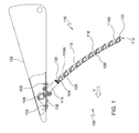
Figure 1 is a side view of a height sensor in accordance with the present invention. -
Figure 2 is a perspective review of the height sensor ofFigure 1 . -
Figure 3 is a cross-sectional view through the length of the height sensor ofFigures 1-2 taken at section line 3-3 inFigure 2 . -
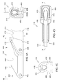
Figures 4A, 4B, 4C and 4D are left side, lower end, upper end, and bottom side views of one of the segments of the sensing arm of the height sensor ofFigures 1-3 . - Referring to
Figures 1-2 , aheight sensor 100 is shown mounted to asupport structure 102. Thesupport structure 102 and theheight sensor 100 travel through an agricultural field in a direction "V". The direction "V" is the harvesting direction: the direction theheight sensor 100 on thesupport structure 102 travel when the crop is being harvested by the agricultural harvesting head on which thesupport structure 102 and theheight sensor 100 are mounted. - The
support structure 102 forms a portion of the frame, or is mounted to the frame of an agricultural harvesting head. In this case, thesupport structure 102 may be employed as a forwardly extending arm for supporting a reciprocating knife at a leading edge of a platform. It may also be employed as a floating arm for supporting a conveyor roller or conveyor belt of a mowing platform also known as a "draper platform" or "draper head". Alternatively it may be employed as a row crop separator disposed at either end or in a central region of a row crop harvesting head. Alternatively it may be employed as a crop divider disposed at either end of the mowing platform. - The
height sensor 100 comprises asensor element 104 that is mounted on aplate 106. The plate is fixed to thesupport structure 102 with a plurality offasteners 108. - The
height sensor 100 further comprisessensor arm 110. Thesensor arm 110 is coupled at its upper end to thesensor element 104. Thesensor arm 110 extends generally downward and rearward. Thesensor arm 110 has alower end 112 that is configured to engage and drag along the surface of the ground. - The
sensor arm 110 comprises anupper portion 114 that encloses a spring (seeFigure 3 ). Theupper portion 114 is fixed at its upper end to thesensor element 104. - The
sensor arm 110 further comprises alower portion 116 that further comprises a plurality (nine in the Figures) ofshaft elements 118, an upper terminatingshaft element 120, and a lower terminatingshaft element 122. Thesensor arm 110 is in the form of an elongate shaft. Each of theindividual shaft elements individual shaft elements sensor arm 110, in the same manner that individual links in a drive chain are coupled together. - Each of the plurality of
shaft elements 118 comprises an upper end that is coupled to a lower end of a first adjacent one of the plurality ofshaft elements 118. - Each of the plurality of
shaft elements 118 comprises a lower end that is coupled to a second adjacent one of the plurality ofshaft elements 118. - All the
shaft elements 118 are identical to each other in configuration, and thus the discussion below regarding each of the plurality ofshaft elements 118 is equally true for all of the plurality ofshaft elements 118. - Each of the plurality of
shaft elements 118 is pivotally coupled to its adjacent ones of the plurality ofshaft elements 118 by pivot pins 124. These pivot pins 124 define a pivot axis 126 (seeFigure 2 ) at the upper end of each one of the plurality ofshaft elements 118 that is parallel to apivot axis 126 at the lower end of each one of the plurality ofshaft elements 118. In this manner, all of the pivot axes126 defined by the pivot pins 124 are parallel to each other and are spaced apart along the length of thelower portion 116. All of the pivot axes 126 extend horizontally and generally laterally with respect to the direction of travel "V" of thesupport structure 102 and the agricultural harvesting head. - An upper terminating
shaft element 120 has a lower end that is configured to engage the upper end of the uppermost one of the plurality ofshaft elements 118. The upper terminatingshaft element 120 has an upper end that is configured to engage the lower end of theupper portion 114. - A lower terminating
shaft element 122 has an upper end that is configured to engage the upper end of the lowermost one of the plurality ofshaft elements 118. The lower terminatingshaft element 122 has a lower end that is configured to engage and drag along the ground. The lower end of the lower terminatingshaft element 122 forms thelower end 112 of thesensor arm 110. - Referring to
Figure 3 , theupper portion 114 of thesensor arm 110 is in the form of a tube that is hollow and defines acavity 300. Thecavity 300 defines a right circular cylinder. Thecavity 300 encloses acoil spring 302. The lower end of thecoil spring 302 abuts the bottom 304 of theupper portion 114 and thecavity 300. The upper end of thecoil spring 302 abuts aspring retainer 306. - The
spring retainer 306 comprises awasher 308 with an aperture passing therethrough. Thewasher 308 is sized to permit it to slide up and down inside thecavity 300. Thespring retainer 306 further comprises a threadedfastener 310 that abuts thewasher 308. Acable 312 that is elongate and flexible is threadedly engaged to the threadedfastener 310 at the upper end of thecable 312. - The
cable 312 extends downward through the coils of thecoil spring 302 and exits thecavity 300 through an aperture in the bottom of theupper portion 114. - The
cable 312 extends through hollow central regions of the upper terminatingshaft element 120, through hollow central regions of the plurality ofshaft elements 118, and through a hollow central region of the lower terminatingshaft element 122. Thecable 312 has aferrule 314 at its lower end that abuts and is retained in the lower terminatingshaft element 122. - In this manner, the
coil spring 302 can be placed in tension. Thecable 312 spring loads theshaft elements cable 312 by thecoil spring 302 pulls together the upper terminatingshaft element 120, the plurality ofshaft elements 118 and the lower terminatingshaft element 122. This tension pulls the shaft elements together and forces them to assume the normal operating shape shown inFigures 1-3 . - As will be explained below in more detail, the individual elements can flex forward with respect to each other, particularly when the agricultural harvesting head is moved in reverse (i.e. opposite the direction of travel "V") with a
lower end 112 dragging on the ground but when thesensor arm 110 is released, the coil spring and cable arrangement automatically returns them to the shape shown inFigures 1-3 . - The upper end of the upper terminating
shaft element 120 describes a ring-shapedguide 316 that is received in a corresponding ring-shapedrecess 318 in the lower end of theupper portion 114. The ring-shapedguide 316 and the ring-shapedrecess 318 are so dimensioned that the upper terminatingshaft element 120 can rotate with respect to theupper portion 114. It rotates about an axis that is generally parallel to the longitudinal extent of thecable 312. Since the upper terminatingshaft element 120, the plurality ofshaft elements 118 and the lower terminatingshaft element 122 are pivotally coupled to each other with the pivot pins 124, this guide and recess arrangement permits thelower portion 116 of thesensor arm 110 to pivot as one with respect to theupper portion 114. -
Figures 4A-4D shows details of eachindividual shaft element 118 of the plurality ofshaft elements 118. Eachshaft element 118 is symmetric about a plane "X" (Figures 4B, 4D ) that extends vertically and in the fore and aft direction of travel "V". - A
first aperture 402 and anabutment 416 are disposed at the upper end of theshaft element 118. Thefirst aperture 402 extends through theupper body portion 404 of theshaft element 118 in a direction perpendicular to the longitudinal extent of theshaft element 118 and perpendicular to the longitudinal extent of thecable 312. - Similarly, two
apertures 406 and are disposed on opposing lateral sides of theshaft element 118 at thelower end 408 of theshaft element 118. The twoapertures 406 are formed in twoflanges 410 disposed on opposite sides of thelower end 408 of theshaft element 118. Amating abutment 418 is also disposed at thelower end 408 of theshaft element 118. - The
upper body portion 404 is dimensioned such that it is received into a gap between the twoflanges 410. In this position, thefirst aperture 402 and the twoapertures 406 are aligned (as best shown inFigure 4A ) in such a manner that one of the pivot pins 124 can be inserted through thefirst aperture 402 and the twoapertures 406 and permit the twoadjacent shaft elements 118 that are thereby pinned together to pivot with respect to each other about thepivot axis 126 defined by thepivot pin 124. - The lower end of the upper terminating
shaft element 120 is configured identical to the lower end of theuppermost shaft element 118A. It is similarly coupled to theuppermost shaft element 118A with apivot pin 124 and similarly pivots with respect to theuppermost shaft element 118A about thepivot axis 126 defined by thepivot pin 124. - The upper end of the lower terminating
shaft element 122 is configured identical to the upper end of thelowermost shaft element 118B. It is similarly coupled to thelowermost shaft element 118B with thepivot pin 124 and similarly pivots with respect to thelowermost shaft element 118B about thepivot axis 126 defined by thepivot pin 124. - The
first aperture 402 and the twoapertures 406 are disposed on the front side of theshaft element 118. The body of theshaft element 118 defines apassageway 414 that is elongate and 414 that passes through the body of theshaft element 118. Eachpassageway 414 is disposed such that it is aligned with asimilar passageway 414 in theadjacent shaft elements 118 to which theshaft element 118 is pinned. In this manner, thepassageway 414 in each of theshaft elements 118 forms a long, continuous passageway that extends substantially the entire length of thelower portion 116 of thesensor arm 110. It is this passageway through which thecable 312 passes. - When the
cable 312 is tensioned (by appropriately tightening or loosening the threadedfastener 310 on the upper end of the cable 312), it pulls the upper terminatingshaft element 120, the plurality ofshaft elements 118, and the lower terminatingshaft element 122 together. It mechanically engages the upper terminatingshaft element 120 and the lower terminatingshaft element 122. All theshaft elements 118 that are disposed between the upper terminatingshaft element 120 and the lower terminatingshaft element 122 are not tensioned directly by thecable 312. Thecable 312 passes freely through theshaft elements 118 and can slide with respect toshaft elements 118 as thelower portion 116 of thesensor arm 110 flexes forward from the position illustrated herein and backward again. The sliding ability of thecable 312 with respect to theindividual shaft elements 118 permits the lower portion to flex that whatever pivot joint defined bypivot pins 124 best reduces the pressure applied by the ground to thelower end 112 of thesensor arm 110, and thereby minimizes the potential for injury to thesensor arm 110. - Further, this arrangement evenly distributes the abutting force between an
abutment 416 and a mating abutment 418 (seeFigure 4 ). Even further, tensioning by a common cable eliminates the necessity of providing a separate tensioning spring at each of the pivot pins 124 to individually apply an abutting force between theabutment 416 and the mating abutment 418 (seeFigure 4 ). - Since all of the
shaft elements cable 312 causes all of theshaft elements pivot pins 124 until anabutment 416 at the upper end of the shaft element 118 (which is disposed on the opposite side of thecable 312 from the pivot pins 124) abuts amating abutment 418 at the lower end of the immediatelyadjacent shaft element 118. This abutting relationship is best shown inFigure 4A . This prevents further rotation of eachshaft element 118 with respect to its adjacent shaft elements. - It is the abutting relationship that causes the
lower portion 116 of thesensor arm 110 to form a rigid, predefined shape having the curvature shown inFigure 1 . - While the abutting relationship prevents the
shaft elements shaft elements coil spring 302 and can increase in length. - In particular, the
lower portion 116 can pivot forward at itslower end 112 even if the upper end of thesensor arm 110 is stationary. As it pivots forward, each of theabutments 416 will be pulled away from itsmating abutment 418, and each of theshaft elements lower portion 116 will pivot forward with respect to theadjacent shaft elements shaft elements height sensor 100 when the agricultural vehicle on which the agricultural harvesting head is supported travels in reverse (i.e. in a direction opposite to the direction "V" of travel during harvesting). - During normal harvesting operations, when the
sensor arm 110 is being dragged along the ground traveling in the direction "V", thelower portion 116 will hold its shape as shown inFigure 1 even as the entire arm pivots up and down with respect to the ground rotating thesensor element 104. This motion causes thesensor element 104 to rotate and to indicate the rising and falling of the ground underneath the support structure 102 (and hence the rising and falling of the agricultural harvesting head). - On occasion, however, the direction of the agricultural harvesting head is reversed and the agricultural harvesting head travels in a direction opposite the direction "V". This will happen, for example, when the operator of the vehicle that carries the agricultural harvesting head reverses its direction of travel and backs the vehicle up.
- When this reversal occurs, the ground upon which the
lower end 112 rests will pull thelower end 112 forward, pivoting each of theshaft elements abutment 416 and themating abutment 418 will be pulled apart, and thecoil spring 302 will be compressed as thecable 312 is pulled downwards into thelower portion 116. Rather than becoming embedded in the ground and breaking off or otherwise being damaged, thesensor arm 110 will survive the reversal undamaged. - The configuration of each of the
shaft elements sensor arm 110 by limiting the ability of dirt, sticks, twigs, or other particulate matter from entering the gap formed between theabutment 416 and themating abutment 418. In particular, theabutment 416 and themating abutment 418 are shingled. An overlapping cover 420 extends outward from theabutment 416 and extends over the top of themating abutment 418. This cover deflects dirt and other contaminants away from between theabutment 416 and themating abutment 418. Furthermore, the twoflanges 410 are disposed the lower end of eachshaft element 118 and extend downward therefrom. The twoflanges 410 extend downward and cover the lateral sides of theupper body portion 404 of theshaft element 118 that is pinned to the twoflanges 410. In this manner, contaminants falling on theshaft element 118 are deflected away from the inner surfaces of the twoflanges 410 that abut theupper body portion 404, which pivot with respect to each other and rub against each other. In effect, this shingles the lateral sides of thesensor arm 110 at each of the joints betweenadjacent shaft elements 118. - Furthermore, by disposing the
first aperture 402 and the twoapertures 406 on the leading edge (i.e. the forward edge) of the sensor arm, there is no gap along the leading edge into which dirt or other contaminants can become embedded. In this manner, the arrangement of the present invention is unlike sensor arms that include a flexible coil spring shaft portion, such as those shown inUS6202395 (B1), for example. In these arrangements, the sensor arm can be flexed in all directions, pulling the adjacent coils apart and thereby permitting contaminants to be inserted between the spring coils, thereby preventing them from returning to their original (unflexed) position. - As an additional advantage, and unlike that shown in the arrangement of
US6202395 (B1), the sensor arm cannot be flexed backwards and thereby give a false reading of height. - As yet another advantage, and also unlike that shown in the arrangement of
US6202395 (B1), the coupling of each of theshaft elements pivot pin 124 prevents thesensor arm 110 from being strangely flexed side-to-side as it travels over the ground. Again, and in comparison, the coil spring arrangement ofUS6202395 (B1) can be flexed from side-to-side as well as forward and backward. The coil spring ofUS6202395 (B1) provides equal flexure of the sensor arm in every direction under the same loads. - Of course, some reduced amount of side to side flexure of the
sensor arm 110 may be beneficial, for example to translate sideways slightly to get around obstructions such as corn stobs in the field which would otherwise give a false indication of height. - This slight sideways translation of the sensor arm 110 (slight as compared to the forward flexure of the
sensor arm 110, which, in the arrangement shown herein can permit thesensor arm 110 to fold in half) can be provided by slightly enlarging thefirst aperture 402 such that a limited degree of side-to-side flexure at each of the joints defined by the pivot pins 124 is allowed. - As yet another advantage, and also unlike that shown in the arrangement of
US6202395 (B1), the total amount of forward flexure of thelower end 112 of thesensor arm 110 when traveling in the reverse direction can be modified by changing the operating length of thecoil spring 302. The shorter the operating length of thecoil spring 302, the shorter the distance that theshaft elements coil spring 302 by one adjustment (i.e. tightening or loosening the threaded fastener 310) the amount of force required to flex thesensor arm 110 forward can be increased or reduced, respectively.
Claims (13)
- A height sensor (100) for an agricultural harvesting head that harvests agricultural crops while traveling in a harvesting direction (V), the height sensor comprising a sensor element (104) and a sensor arm (110), the sensor arm comprising a plurality of shaft elements (118, 120, 122), wherein each of the plurality of shaft elements (118, 120, 122) is pivotally coupled to an adjacent one of the plurality of shaft elements (118, 120, 122), and wherein the plurality of shaft elements (118, 120, 122) are held in a predefined operating position by a cable (312), and further wherein the cable (312) extends through the plurality of shaft elements (118).
- The height sensor (100) of Claim 1, wherein each of the plurality of shaft elements (118, 120) defines a passageway (414) extending therethrough, and through which the cable (312) extends.
- The height sensor (100) of Claim 1, wherein the cable (312) is anchored at one end to a lower one of the plurality of shaft elements (122), is slidingly supported in and extends through a second plurality (118) of the plurality of shaft elements (118, 120).
- The height sensor (100) of Claim 3, further comprising a coil spring (302) disposed at an upper end of the sensor arm (110).
- The height sensor (100) of Claim 4, wherein the cable (312) has an upper end, and further wherein the upper end of the cable (312) is coupled to the coil spring (302).
- The height sensor (100) of Claim 5, wherein the cable (312) is preloaded to hold the sensor arm (110) into a fixed operating shape.
- The height sensor (100) of Claim 1, further comprising a plurality of pivot pins (124), wherein each of the plurality of pivot pins (124) pivotally couples said each of the plurality of shaft elements (118, 120, 122) to said an adjacent one of the plurality of shaft elements (118, 120, 122).
- The height sensor (100) of Claim 7, wherein each of the plurality of pivot pins (124) extends perpendicular to the harvesting direction (V).
- The height sensor (100) of Claim 8, wherein each of the plurality of pivot pins (124) extend in a direction parallel to others of the plurality of pivot pins (124).
- The height sensor (100) of Claim 1, wherein each of the plurality of shaft elements (118) is identically constructed to others of the plurality of shaft elements (118).
- The height sensor (100) of Claim 1, wherein an upper end of each of said plurality of shaft elements (118, 122) is received into a lower end of each of said plurality of shaft elements (118, 120).
- The height sensor (100) of Claim 11, wherein the lower end of each of said plurality of shaft elements (118, 120) is shingled over the upper end of another of each of said plurality of shaft elements (118, 122).
- A header with a height sensor (100) according to one of the preceding claims.
Applications Claiming Priority (1)
| Application Number | Priority Date | Filing Date | Title |
|---|---|---|---|
| US14/060,230 US20150107209A1 (en) | 2013-10-22 | 2013-10-22 | Height Sensor for Harvesting Head |
Publications (1)
| Publication Number | Publication Date |
|---|---|
| EP2865257A1 true EP2865257A1 (en) | 2015-04-29 |
Family
ID=51627983
Family Applications (1)
| Application Number | Title | Priority Date | Filing Date |
|---|---|---|---|
| EP20140186107 Withdrawn EP2865257A1 (en) | 2013-10-22 | 2014-09-24 | Height sensor for harvesting head |
Country Status (7)
| Country | Link |
|---|---|
| US (1) | US20150107209A1 (en) |
| EP (1) | EP2865257A1 (en) |
| CN (1) | CN104541784A (en) |
| AR (1) | AR098149A1 (en) |
| BR (1) | BR102014026116A2 (en) |
| CA (1) | CA2868182A1 (en) |
| EA (1) | EA201401008A1 (en) |
Cited By (2)
| Publication number | Priority date | Publication date | Assignee | Title |
|---|---|---|---|---|
| EP3360406A1 (en) * | 2017-02-10 | 2018-08-15 | CNH Industrial Belgium NV | Ground height gauge assembly |
| EP3711472A1 (en) | 2019-03-22 | 2020-09-23 | CLAAS Selbstfahrende Erntemaschinen GmbH | Push button |
Families Citing this family (6)
| Publication number | Priority date | Publication date | Assignee | Title |
|---|---|---|---|---|
| US9980431B2 (en) * | 2016-09-12 | 2018-05-29 | Cnh Industrial America Llc | Header height control system with multiple height sensors |
| CN110199664A (en) * | 2019-04-09 | 2019-09-06 | 丰疆智能科技股份有限公司 | Work machine and its control method are cut in the agriculture that the drop ceding of Taiwan can be lifted |
| WO2022147601A1 (en) * | 2021-01-05 | 2022-07-14 | Da Silva Moacir Munhoz Sanchez | Support for maize harvester platform height control sensor |
| EP4260674A1 (en) * | 2022-04-13 | 2023-10-18 | CNH Industrial Polska Sp. z o.o. | Height sensor arrangement for a combine header |
| US12484474B2 (en) * | 2023-01-09 | 2025-12-02 | Cnh Industrial America Llc | Breakaway rigid header height control system |
| US20250000004A1 (en) * | 2023-06-30 | 2025-01-02 | Deere & Company | Crop feeler device for machine row guidance |
Citations (4)
| Publication number | Priority date | Publication date | Assignee | Title |
|---|---|---|---|---|
| US6202395B1 (en) | 1997-12-31 | 2001-03-20 | Richard Gramm | Combine header height control |
| EP1155607A1 (en) * | 2000-05-16 | 2001-11-21 | Deere & Company | Height feeler for harvester head |
| CA2511418A1 (en) | 2004-07-29 | 2006-01-29 | Richard Gramm | Height sensor arrangement for agricultural applications |
| EP1911342A2 (en) * | 2006-10-11 | 2008-04-16 | Maschinenfabrik Kemper GmbH & Co. KG | Height sensor for a header |
Family Cites Families (14)
| Publication number | Priority date | Publication date | Assignee | Title |
|---|---|---|---|---|
| US2545452A (en) * | 1946-10-01 | 1951-03-20 | Maurice J Fletcher | Segmented articulated finger |
| US2752835A (en) * | 1951-11-01 | 1956-07-03 | Preston M Wright | Depth control for plows and the like |
| US3611286A (en) * | 1970-03-20 | 1971-10-05 | Arthur B Cleveland | Device for sensing the position of a moving vehicle with respect to a furrow |
| US4661039A (en) * | 1983-10-20 | 1987-04-28 | Donaldson Company | Flexible-frame robot |
| US4833876A (en) * | 1987-04-09 | 1989-05-30 | Tsubakimoto Chain Co. | Carrier for cables and the like |
| US5088561A (en) * | 1990-11-02 | 1992-02-18 | Sukup Manufacturing Company | Sensing apparatus for a guidance system |
| DE4105651A1 (en) * | 1991-02-22 | 1992-09-03 | Kabelschlepp Gmbh | POWER SUPPLY CHAIN |
| US5108350A (en) * | 1991-03-06 | 1992-04-28 | A&A Manufacturing Co., Inc. | Conduit carrier chain |
| DE4121433C1 (en) * | 1991-06-28 | 1993-02-04 | Ekd Gelenkrohr Gmbh, 4006 Erkrath, De | |
| JP3356659B2 (en) * | 1996-10-16 | 2002-12-16 | 株式会社椿本チエイン | Cable drag chain |
| JP3722482B2 (en) * | 2003-02-17 | 2005-11-30 | 株式会社椿本チエイン | Cable protection guide device |
| US6883299B1 (en) * | 2003-08-05 | 2005-04-26 | Richard Gramm | Height sensor arrangement for agricultural applications |
| US8489239B2 (en) * | 2010-11-01 | 2013-07-16 | GM Global Technology Operations LLC | Robust operation of tendon-driven robot fingers using force and position-based control laws |
| US8201388B1 (en) * | 2011-05-02 | 2012-06-19 | Deere & Company | Sensor for a header height control system |
-
2013
- 2013-10-22 US US14/060,230 patent/US20150107209A1/en not_active Abandoned
-
2014
- 2014-09-24 EP EP20140186107 patent/EP2865257A1/en not_active Withdrawn
- 2014-10-13 EA EA201401008A patent/EA201401008A1/en unknown
- 2014-10-20 BR BR102014026116A patent/BR102014026116A2/en not_active IP Right Cessation
- 2014-10-21 CA CA 2868182 patent/CA2868182A1/en not_active Abandoned
- 2014-10-22 AR ARP140103964A patent/AR098149A1/en unknown
- 2014-10-22 CN CN201410566787.8A patent/CN104541784A/en active Pending
Patent Citations (4)
| Publication number | Priority date | Publication date | Assignee | Title |
|---|---|---|---|---|
| US6202395B1 (en) | 1997-12-31 | 2001-03-20 | Richard Gramm | Combine header height control |
| EP1155607A1 (en) * | 2000-05-16 | 2001-11-21 | Deere & Company | Height feeler for harvester head |
| CA2511418A1 (en) | 2004-07-29 | 2006-01-29 | Richard Gramm | Height sensor arrangement for agricultural applications |
| EP1911342A2 (en) * | 2006-10-11 | 2008-04-16 | Maschinenfabrik Kemper GmbH & Co. KG | Height sensor for a header |
Non-Patent Citations (1)
| Title |
|---|
| PALLI, GIANLUCA: "Model and Control of Tendon Actuated Robots", 2007, Bologna, Italy, XP055172121, Retrieved from the Internet <URL:http://amsdottorato.unibo.it/341/1/GianlucaPalli_PhDthesis.pdf> [retrieved on 20150225] * |
Cited By (3)
| Publication number | Priority date | Publication date | Assignee | Title |
|---|---|---|---|---|
| EP3360406A1 (en) * | 2017-02-10 | 2018-08-15 | CNH Industrial Belgium NV | Ground height gauge assembly |
| US10306829B2 (en) | 2017-02-10 | 2019-06-04 | Cnh Industrial America Llc | Ground height gauge assembly |
| EP3711472A1 (en) | 2019-03-22 | 2020-09-23 | CLAAS Selbstfahrende Erntemaschinen GmbH | Push button |
Also Published As
| Publication number | Publication date |
|---|---|
| CA2868182A1 (en) | 2015-04-22 |
| BR102014026116A2 (en) | 2015-09-22 |
| AR098149A1 (en) | 2016-05-04 |
| CN104541784A (en) | 2015-04-29 |
| EA201401008A1 (en) | 2015-04-30 |
| US20150107209A1 (en) | 2015-04-23 |
Similar Documents
| Publication | Publication Date | Title |
|---|---|---|
| US20150107209A1 (en) | Height Sensor for Harvesting Head | |
| US7992372B1 (en) | Draper platform with breakaway joint | |
| US8087224B1 (en) | Flexible draper platform with pivot geometry | |
| US9072222B2 (en) | Self-centering cover for hinged row crop harvesting head | |
| EP2710879B1 (en) | Hinged frame row crop auger conveyor | |
| US8220235B2 (en) | Corn head stripper plate adjusting mechanism | |
| EP2119334B1 (en) | Sensing assembly for detection of one or more plants | |
| CA2827677C (en) | Hinged row crop harvesting head | |
| US8146335B2 (en) | Sensor for a header height control system | |
| RU2619226C2 (en) | Cloth reaper with turning assembly rollers | |
| US10021832B2 (en) | Row divider having a conveyor for an agricultural harvester | |
| EP2896283A2 (en) | Draper header with belt cleaning arrangement | |
| US20220000029A1 (en) | Remotely adjustable row divider for an agricultural harvester | |
| EP2524590A1 (en) | Pivoting center conveyor for draper platform | |
| US20150250098A1 (en) | Stalk Breaker for a Corn Head | |
| US9622413B2 (en) | Agricultual harvesting head with wiper for crop divider | |
| EP2772130A1 (en) | Draper belt platform with additional conveyor in transition area | |
| EP2769612A1 (en) | Frusto-conical conveyor with retracting fingers | |
| US8572942B2 (en) | Curved profile seed pans | |
| US20200253124A1 (en) | Crop flow assistance for harvesting header | |
| EP2708110A1 (en) | Self-adjusting object deflector for an agricultural harvester feeder | |
| US20130160416A1 (en) | Trash finger | |
| JPH06253652A (en) | Reaping and harvesting structure of whole culm feeding combine harvester | |
| US12484474B2 (en) | Breakaway rigid header height control system |
Legal Events
| Date | Code | Title | Description |
|---|---|---|---|
| PUAI | Public reference made under article 153(3) epc to a published international application that has entered the european phase |
Free format text: ORIGINAL CODE: 0009012 |
|
| 17P | Request for examination filed |
Effective date: 20140924 |
|
| AK | Designated contracting states |
Kind code of ref document: A1 Designated state(s): AL AT BE BG CH CY CZ DE DK EE ES FI FR GB GR HR HU IE IS IT LI LT LU LV MC MK MT NL NO PL PT RO RS SE SI SK SM TR |
|
| AX | Request for extension of the european patent |
Extension state: BA ME |
|
| R17P | Request for examination filed (corrected) |
Effective date: 20151029 |
|
| RBV | Designated contracting states (corrected) |
Designated state(s): AL AT BE BG CH CY CZ DE DK EE ES FI FR GB GR HR HU IE IS IT LI LT LU LV MC MK MT NL NO PL PT RO RS SE SI SK SM TR |
|
| GRAP | Despatch of communication of intention to grant a patent |
Free format text: ORIGINAL CODE: EPIDOSNIGR1 |
|
| INTG | Intention to grant announced |
Effective date: 20160425 |
|
| RIN1 | Information on inventor provided before grant (corrected) |
Inventor name: POTLURI, KRISHNA S Inventor name: PIERSON, JOSHUA |
|
| STAA | Information on the status of an ep patent application or granted ep patent |
Free format text: STATUS: THE APPLICATION IS DEEMED TO BE WITHDRAWN |
|
| 18D | Application deemed to be withdrawn |
Effective date: 20160906 |