EP3709015A2 - Bodenzustandbewertungsvorrichtung, bodenzustandbewertungsverfahren und programm - Google Patents
Bodenzustandbewertungsvorrichtung, bodenzustandbewertungsverfahren und programm Download PDFInfo
- Publication number
- EP3709015A2 EP3709015A2 EP20160633.2A EP20160633A EP3709015A2 EP 3709015 A2 EP3709015 A2 EP 3709015A2 EP 20160633 A EP20160633 A EP 20160633A EP 3709015 A2 EP3709015 A2 EP 3709015A2
- Authority
- EP
- European Patent Office
- Prior art keywords
- soil
- vibrations
- feature
- information
- ground surface
- Prior art date
- Legal status (The legal status is an assumption and is not a legal conclusion. Google has not performed a legal analysis and makes no representation as to the accuracy of the status listed.)
- Ceased
Links
- 239000002689 soil Substances 0.000 title claims abstract description 391
- 238000000034 method Methods 0.000 title claims description 20
- 238000000605 extraction Methods 0.000 claims abstract description 21
- XLYOFNOQVPJJNP-UHFFFAOYSA-N water Substances O XLYOFNOQVPJJNP-UHFFFAOYSA-N 0.000 claims description 15
- 239000000203 mixture Substances 0.000 claims description 11
- 230000000644 propagated effect Effects 0.000 claims description 9
- 239000000284 extract Substances 0.000 abstract description 8
- 238000010586 diagram Methods 0.000 description 18
- 238000004891 communication Methods 0.000 description 8
- 230000006870 function Effects 0.000 description 8
- 238000004088 simulation Methods 0.000 description 5
- 238000002474 experimental method Methods 0.000 description 4
- 238000005259 measurement Methods 0.000 description 4
- 238000012545 processing Methods 0.000 description 4
- 238000012546 transfer Methods 0.000 description 4
- 230000005540 biological transmission Effects 0.000 description 3
- 239000004927 clay Substances 0.000 description 3
- 238000007542 hardness measurement Methods 0.000 description 3
- 238000004364 calculation method Methods 0.000 description 2
- 238000005401 electroluminescence Methods 0.000 description 2
- 230000003287 optical effect Effects 0.000 description 2
- 230000035515 penetration Effects 0.000 description 2
- 239000004065 semiconductor Substances 0.000 description 2
- 238000007796 conventional method Methods 0.000 description 1
- 230000007423 decrease Effects 0.000 description 1
- 230000000694 effects Effects 0.000 description 1
- 230000005520 electrodynamics Effects 0.000 description 1
- 238000005516 engineering process Methods 0.000 description 1
- 239000012530 fluid Substances 0.000 description 1
- 238000010348 incorporation Methods 0.000 description 1
- 230000010354 integration Effects 0.000 description 1
- 239000011499 joint compound Substances 0.000 description 1
- 239000004973 liquid crystal related substance Substances 0.000 description 1
- 238000007639 printing Methods 0.000 description 1
- 239000004576 sand Substances 0.000 description 1
- 238000004856 soil analysis Methods 0.000 description 1
Images





Classifications
-
- G—PHYSICS
- G01—MEASURING; TESTING
- G01N—INVESTIGATING OR ANALYSING MATERIALS BY DETERMINING THEIR CHEMICAL OR PHYSICAL PROPERTIES
- G01N33/00—Investigating or analysing materials by specific methods not covered by groups G01N1/00 - G01N31/00
- G01N33/24—Earth materials
- G01N33/246—Earth materials for water content
-
- G—PHYSICS
- G01—MEASURING; TESTING
- G01H—MEASUREMENT OF MECHANICAL VIBRATIONS OR ULTRASONIC, SONIC OR INFRASONIC WAVES
- G01H1/00—Measuring characteristics of vibrations in solids by using direct conduction to the detector
- G01H1/04—Measuring characteristics of vibrations in solids by using direct conduction to the detector of vibrations which are transverse to direction of propagation
- G01H1/06—Frequency
-
- G—PHYSICS
- G01—MEASURING; TESTING
- G01N—INVESTIGATING OR ANALYSING MATERIALS BY DETERMINING THEIR CHEMICAL OR PHYSICAL PROPERTIES
- G01N29/00—Investigating or analysing materials by the use of ultrasonic, sonic or infrasonic waves; Visualisation of the interior of objects by transmitting ultrasonic or sonic waves through the object
- G01N29/04—Analysing solids
- G01N29/045—Analysing solids by imparting shocks to the workpiece and detecting the vibrations or the acoustic waves caused by the shocks
-
- G—PHYSICS
- G01—MEASURING; TESTING
- G01N—INVESTIGATING OR ANALYSING MATERIALS BY DETERMINING THEIR CHEMICAL OR PHYSICAL PROPERTIES
- G01N29/00—Investigating or analysing materials by the use of ultrasonic, sonic or infrasonic waves; Visualisation of the interior of objects by transmitting ultrasonic or sonic waves through the object
- G01N29/04—Analysing solids
- G01N29/07—Analysing solids by measuring propagation velocity or propagation time of acoustic waves
-
- G—PHYSICS
- G01—MEASURING; TESTING
- G01N—INVESTIGATING OR ANALYSING MATERIALS BY DETERMINING THEIR CHEMICAL OR PHYSICAL PROPERTIES
- G01N29/00—Investigating or analysing materials by the use of ultrasonic, sonic or infrasonic waves; Visualisation of the interior of objects by transmitting ultrasonic or sonic waves through the object
- G01N29/04—Analysing solids
- G01N29/12—Analysing solids by measuring frequency or resonance of acoustic waves
-
- G—PHYSICS
- G01—MEASURING; TESTING
- G01N—INVESTIGATING OR ANALYSING MATERIALS BY DETERMINING THEIR CHEMICAL OR PHYSICAL PROPERTIES
- G01N29/00—Investigating or analysing materials by the use of ultrasonic, sonic or infrasonic waves; Visualisation of the interior of objects by transmitting ultrasonic or sonic waves through the object
- G01N29/22—Details, e.g. general constructional or apparatus details
- G01N29/24—Probes
- G01N29/2481—Wireless probes, e.g. with transponders or radio links
-
- G—PHYSICS
- G01—MEASURING; TESTING
- G01N—INVESTIGATING OR ANALYSING MATERIALS BY DETERMINING THEIR CHEMICAL OR PHYSICAL PROPERTIES
- G01N29/00—Investigating or analysing materials by the use of ultrasonic, sonic or infrasonic waves; Visualisation of the interior of objects by transmitting ultrasonic or sonic waves through the object
- G01N29/34—Generating the ultrasonic, sonic or infrasonic waves, e.g. electronic circuits specially adapted therefor
- G01N29/348—Generating the ultrasonic, sonic or infrasonic waves, e.g. electronic circuits specially adapted therefor with frequency characteristics, e.g. single frequency signals, chirp signals
-
- G—PHYSICS
- G01—MEASURING; TESTING
- G01N—INVESTIGATING OR ANALYSING MATERIALS BY DETERMINING THEIR CHEMICAL OR PHYSICAL PROPERTIES
- G01N29/00—Investigating or analysing materials by the use of ultrasonic, sonic or infrasonic waves; Visualisation of the interior of objects by transmitting ultrasonic or sonic waves through the object
- G01N29/36—Detecting the response signal, e.g. electronic circuits specially adapted therefor
- G01N29/38—Detecting the response signal, e.g. electronic circuits specially adapted therefor by time filtering, e.g. using time gates
-
- G—PHYSICS
- G01—MEASURING; TESTING
- G01N—INVESTIGATING OR ANALYSING MATERIALS BY DETERMINING THEIR CHEMICAL OR PHYSICAL PROPERTIES
- G01N29/00—Investigating or analysing materials by the use of ultrasonic, sonic or infrasonic waves; Visualisation of the interior of objects by transmitting ultrasonic or sonic waves through the object
- G01N29/36—Detecting the response signal, e.g. electronic circuits specially adapted therefor
- G01N29/42—Detecting the response signal, e.g. electronic circuits specially adapted therefor by frequency filtering or by tuning to resonant frequency
-
- G—PHYSICS
- G01—MEASURING; TESTING
- G01N—INVESTIGATING OR ANALYSING MATERIALS BY DETERMINING THEIR CHEMICAL OR PHYSICAL PROPERTIES
- G01N29/00—Investigating or analysing materials by the use of ultrasonic, sonic or infrasonic waves; Visualisation of the interior of objects by transmitting ultrasonic or sonic waves through the object
- G01N29/44—Processing the detected response signal, e.g. electronic circuits specially adapted therefor
- G01N29/4409—Processing the detected response signal, e.g. electronic circuits specially adapted therefor by comparison
- G01N29/4436—Processing the detected response signal, e.g. electronic circuits specially adapted therefor by comparison with a reference signal
-
- G—PHYSICS
- G01—MEASURING; TESTING
- G01N—INVESTIGATING OR ANALYSING MATERIALS BY DETERMINING THEIR CHEMICAL OR PHYSICAL PROPERTIES
- G01N29/00—Investigating or analysing materials by the use of ultrasonic, sonic or infrasonic waves; Visualisation of the interior of objects by transmitting ultrasonic or sonic waves through the object
- G01N29/44—Processing the detected response signal, e.g. electronic circuits specially adapted therefor
- G01N29/4454—Signal recognition, e.g. specific values or portions, signal events, signatures
-
- G—PHYSICS
- G01—MEASURING; TESTING
- G01N—INVESTIGATING OR ANALYSING MATERIALS BY DETERMINING THEIR CHEMICAL OR PHYSICAL PROPERTIES
- G01N29/00—Investigating or analysing materials by the use of ultrasonic, sonic or infrasonic waves; Visualisation of the interior of objects by transmitting ultrasonic or sonic waves through the object
- G01N29/44—Processing the detected response signal, e.g. electronic circuits specially adapted therefor
- G01N29/4472—Mathematical theories or simulation
-
- G—PHYSICS
- G01—MEASURING; TESTING
- G01N—INVESTIGATING OR ANALYSING MATERIALS BY DETERMINING THEIR CHEMICAL OR PHYSICAL PROPERTIES
- G01N33/00—Investigating or analysing materials by specific methods not covered by groups G01N1/00 - G01N31/00
- G01N33/24—Earth materials
-
- E—FIXED CONSTRUCTIONS
- E02—HYDRAULIC ENGINEERING; FOUNDATIONS; SOIL SHIFTING
- E02D—FOUNDATIONS; EXCAVATIONS; EMBANKMENTS; UNDERGROUND OR UNDERWATER STRUCTURES
- E02D1/00—Investigation of foundation soil in situ
- E02D1/02—Investigation of foundation soil in situ before construction work
- E02D1/022—Investigation of foundation soil in situ before construction work by investigating mechanical properties of the soil
-
- G—PHYSICS
- G01—MEASURING; TESTING
- G01N—INVESTIGATING OR ANALYSING MATERIALS BY DETERMINING THEIR CHEMICAL OR PHYSICAL PROPERTIES
- G01N2291/00—Indexing codes associated with group G01N29/00
- G01N2291/01—Indexing codes associated with the measuring variable
- G01N2291/014—Resonance or resonant frequency
-
- G—PHYSICS
- G01—MEASURING; TESTING
- G01N—INVESTIGATING OR ANALYSING MATERIALS BY DETERMINING THEIR CHEMICAL OR PHYSICAL PROPERTIES
- G01N2291/00—Indexing codes associated with group G01N29/00
- G01N2291/02—Indexing codes associated with the analysed material
- G01N2291/023—Solids
- G01N2291/0231—Composite or layered materials
-
- G—PHYSICS
- G01—MEASURING; TESTING
- G01N—INVESTIGATING OR ANALYSING MATERIALS BY DETERMINING THEIR CHEMICAL OR PHYSICAL PROPERTIES
- G01N2291/00—Indexing codes associated with group G01N29/00
- G01N2291/02—Indexing codes associated with the analysed material
- G01N2291/024—Mixtures
- G01N2291/02458—Solids in solids, e.g. granules
-
- G—PHYSICS
- G01—MEASURING; TESTING
- G01N—INVESTIGATING OR ANALYSING MATERIALS BY DETERMINING THEIR CHEMICAL OR PHYSICAL PROPERTIES
- G01N2291/00—Indexing codes associated with group G01N29/00
- G01N2291/02—Indexing codes associated with the analysed material
- G01N2291/028—Material parameters
- G01N2291/02827—Elastic parameters, strength or force
-
- G—PHYSICS
- G01—MEASURING; TESTING
- G01N—INVESTIGATING OR ANALYSING MATERIALS BY DETERMINING THEIR CHEMICAL OR PHYSICAL PROPERTIES
- G01N2291/00—Indexing codes associated with group G01N29/00
- G01N2291/02—Indexing codes associated with the analysed material
- G01N2291/028—Material parameters
- G01N2291/02845—Humidity, wetness
-
- G—PHYSICS
- G01—MEASURING; TESTING
- G01N—INVESTIGATING OR ANALYSING MATERIALS BY DETERMINING THEIR CHEMICAL OR PHYSICAL PROPERTIES
- G01N2291/00—Indexing codes associated with group G01N29/00
- G01N2291/02—Indexing codes associated with the analysed material
- G01N2291/028—Material parameters
- G01N2291/0289—Internal structure, e.g. defects, grain size, texture
-
- G—PHYSICS
- G01—MEASURING; TESTING
- G01N—INVESTIGATING OR ANALYSING MATERIALS BY DETERMINING THEIR CHEMICAL OR PHYSICAL PROPERTIES
- G01N2291/00—Indexing codes associated with group G01N29/00
- G01N2291/10—Number of transducers
- G01N2291/102—Number of transducers one emitter, one receiver
-
- G—PHYSICS
- G01—MEASURING; TESTING
- G01N—INVESTIGATING OR ANALYSING MATERIALS BY DETERMINING THEIR CHEMICAL OR PHYSICAL PROPERTIES
- G01N27/00—Investigating or analysing materials by the use of electric, electrochemical, or magnetic means
- G01N27/02—Investigating or analysing materials by the use of electric, electrochemical, or magnetic means by investigating impedance
- G01N27/22—Investigating or analysing materials by the use of electric, electrochemical, or magnetic means by investigating impedance by investigating capacitance
- G01N27/223—Investigating or analysing materials by the use of electric, electrochemical, or magnetic means by investigating impedance by investigating capacitance for determining moisture content, e.g. humidity
-
- G—PHYSICS
- G01—MEASURING; TESTING
- G01N—INVESTIGATING OR ANALYSING MATERIALS BY DETERMINING THEIR CHEMICAL OR PHYSICAL PROPERTIES
- G01N33/00—Investigating or analysing materials by specific methods not covered by groups G01N1/00 - G01N31/00
- G01N33/24—Earth materials
- G01N33/245—Earth materials for agricultural purposes
Definitions
- the present invention relates to a soil condition estimation apparatus, a soil condition estimation method, and a program for estimating soil conditions.
- Japanese Patent Laid-Open Publication No. H11-94732 discloses a soil surface hardness measurement apparatus for measuring the hardness of a soil surface (ground surface).
- This soil surface hardness measurement apparatus drops a cone-shaped sensor of which the penetration depth thereof changes depending on the hardness of a ground surface, so that the sensor falls freely and penetrates soil, and the hardness of the soil surface is measured based on the penetration depth of the sensor.
- WO 2016/136213 discloses a soil quality determination apparatus that determines the type and density of soil as a related technology. This soil quality determination apparatus measures the type and density of soil based on frequency characteristic vibrations, which indicate frequency characteristics of vibrations of soil, and the amount of water.
- the soil surface hardness measurement apparatus disclosed in Japanese Patent Laid-Open Publication No. H11-94732 is an apparatus for measuring the hardness of a ground surface, and this apparatus cannot be employed when the hardness of soil inside the ground is to be measured. Also, this apparatus causes a cone-shaped sensor to freely fall onto a ground surface, and is therefore not suitable for measuring the hardness of a soft soil such as a soil of a farm field. This is because, if a ridge or the like has been formed in the field, the sensor may damage the ridge.
- the soil quality determination apparatus disclosed in WO 2016/136213 can determine the type and density of soil without damaging the ground surface. However, the soil quality determination apparatus disclosed in WO 2016/136213 is not designed to estimate soil conditions at various depths.
- An example object of the present invention is to provide a soil condition estimation apparatus, a soil condition estimation method, and a program for estimating soil conditions at various depths.
- a soil condition estimation apparatus includes:
- a soil condition estimation method includes:
- FIG. 1 is a diagram illustrating an example of a soil condition estimation apparatus.
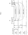
- FIG. 2 is a diagram illustrating soil, and propagation time.
- the soil condition estimation apparatus 1 shown in FIG. 1 is an apparatus that estimates conditions of soil at various depths. As shown in FIG. 1 , the soil condition estimation apparatus 1 includes a selection unit 2, an extraction unit 3, and an estimation unit 4.
- the selection unit 2 selects, by using a propagation time, which is the time it takes for vibrations to propagate through soil, vibrations that have been measured from soil, according to the depth of soil. That is to say, the selection unit selects vibrations corresponding to the depth of soil, based on the fact that the propagation time varies depending on the depth of soil.
- the depth of soil can be expressed as the distance thereof from the ground surface (soil surface) in a vertical direction, for example.
- a soil that ranges from the soil surface to a distance L1 is referred to as a soil layer 1
- a soil that ranges from the distance L1 to a distance L2 is referred to as a soil layer 2
- a soil that ranges from the distance L2 to a distance L3 is referred to as a soil layer 3.
- the propagation time is, specifically, the period of time that elapses from when vibrations are applied to the ground surface of the subject soil to when vibrations corresponding to the applied vibrations are measured at the soil surface.
- a vibrator 21 may be provided on the ground surface to apply vibrations to soil, for example.
- a vibration meter 22 may be provided on the soil surface to measure vibrations that have propagated to the soil surface as a result of the applied vibrations, for example.
- T1 denotes the propagation time of vibrations 1 (a solid line) that propagate to the vibration meter 22 through the soil layer 1
- T2 denotes the propagation time of vibrations 2 (dotted line) that propagate to the vibration meter 22 through the soil layer 2
- T3 denotes the propagation time of vibrations 3 (dashed-dotted line) that propagate to the vibration meter 22 through the soil layer 3.
- the extraction unit 3 extracts a feature of the selected vibrations.
- a feature of vibrations is, for example, information that indicates a feature such as a resonance frequency.
- the estimation unit 4 estimates soil conditions by referencing soil estimation information in which features and soil conditions are associated with each other, using the extracted feature.
- Soil conditions include, for example, the hardness of soil, the amount of roots contained in soil, the amount of water contained in soil, the composition of soil, and so on. However, soil conditions are not limited to the aforementioned conditions.
- FIG. 3 is a diagram illustrating an example of a system that includes the soil condition estimation apparatus.
- a system 20 that includes the soil condition estimation apparatus 1 includes the vibrator 21, the vibration meter 22, and an output device 23 in addition to the soil condition estimation apparatus 1.
- the soil condition estimation apparatus 1 includes a control unit 24, a collecting unit 25, and an output information generation unit 26 in addition to the selection unit 2, the extraction unit 3, and the estimation unit 4.
- the vibrator 21 is a device that is used to apply vibrations to soil. Specifically, the vibrator 21 is provided on the ground surface of soil, and applies vibrations to the soil. The vibrator 21 first acquires, from the control unit 24, vibration setting information that is used to set vibrations that are to be applied by the vibrator 21. Vibration setting information is, for example, information that is used to set a vibration force and a vibration frequency, for example.
- the vibrator 21 upon acquiring vibration setting information from the control unit 24, causes soil to vibrate, based on the vibration setting information.
- vibration methods include a method through which the vibration frequency is swept so that vibrations are generated at a plurality of frequencies in the soil.
- the vibrator 21 may be a mechanical, hydraulic, electrodynamic, piezoelectric, or electromagnetic vibrator, or a hummer, for example.
- the vibrator 21 need only apply vibrations so as not to damage a ridge or the like formed on a soft soil such as a soil of a farm field.
- the vibrator 21 communicates with the control unit 24 via wireless communication, wired communication, or the like.
- the vibration meter 22 is a device for measuring vibrations applied to soil. Specifically, the vibration meter 22 is provided on the ground surface, and measures vibrations applied by the vibrator 21 to soil, from the soil. Next, the vibration meter 22 outputs vibration information that indicates the measured vibrations, to the collecting unit 25.
- the vibration meter 22 may be a mechanical, electromagnetic, piezoelectric, optical, or electromagnetic vibration meter, for example.
- the vibration meter 22 communicates with the control unit 25 via wireless communication, wired communication, or the like.
- the output device 23 acquires output information that has been converted by the output information generation unit 26 so as to be in an outputtable format, and outputs an image, a sound, or the like that is generated based on the output information.
- the output device 23 is, for example, an image display device that employs a liquid crystal, organic EL (Electro Luminescence), or a CRT (Cathode Ray Tube).
- the image display device may also include a sound output device such as a speaker.
- the output device 23 may be a printing device such as a printer. Output information will be described later.
- the following describes the soil condition estimation apparatus.
- the control unit 24 controls at least the vibrator 21 and the collecting unit 25. Specifically, the control unit 24 performs control to transmit vibration setting information to the vibrator 21 and cause the vibrator 21 to apply vibrations. Also, the control unit 24 transmits a vibration start instruction to the collecting unit 25 and causes the collecting unit 25 to collect pieces of vibration information.
- the collecting unit 25 collects pieces of vibration information from the vibration meter 22. Specifically, the collecting unit 25 first collects pieces of vibration information from vibration meter 22 in time series. Next, the collecting unit 25 outputs the pieces of vibration information thus collected to the selection unit 2. The collecting unit 25 also stores pieces of vibration information in a storage unit (not shown).
- the storage unit may be provided inside the soil condition estimation apparatus 1, or provided outside the soil condition estimation apparatus 1.
- the selection unit 2 selects a piece of vibration information corresponding to the subject soil layer from among the pieces of vibration information collected by the collecting unit 25, based on the propagation time of vibrations corresponding to the depth of the subject soil (soil layer). Specifically, the selection unit 2 first acquires pieces of vibration information from the collecting unit 25.
- the selection unit 2 calculates a selection time period based on the propagation time corresponding to the subject soil layer. For example, when the piece of vibration information corresponding to the soil layer 1 is selected, the selection unit 2 calculates the time (selection time period) from when vibrations are applied by the vibrator 21 to soil to when the vibrations 1 that have been reflected by the soil layer 1 can be measured by the vibration meter 22, using the propagation time T1 corresponding to the soil layer 1.
- a selection time period ts1 corresponding to the soil layer 1 is a period of time from a point in time te1-a1, which is earlier than the point in time te1, to a point in time te1+b1, at which vibrations reflected by the soil layer 1 are no longer detectable.
- time a1 start information
- time b1 end information
- selection time periods ts2, ts3, and so on are respectively calculated for the soil layers 2, 3, and so on other than the soil layer 1.
- FIG. 4 is a diagram illustrating an example of a data structure of selection time period generation information.
- the above-described propagation time, start information, and end information regarding each soil layer are stored in the storage unit in advance such that the propagation time, start information, and end information are associated with each other as shown in selection time period generation information 41 in FIG. 4 .
- soil layers, propagation times, and selection time periods may be stored in the storage unit in advance in association with each other as shown in selection time period generation information 42 in FIG. 4 .
- the selection unit 2 selects a piece of vibration information corresponding to the subject soil layer from among the acquired pieces of vibration information, using the selection time period. That is to say, the selection unit 2 selects the piece of vibration information measured in the selection time period corresponding to the subject soil layer.
- the extraction unit 3 extracts a feature of vibrations, using the piece of vibration information thus acquired.
- features of vibrations include a resonance frequency.
- the extraction unit 3 first acquires reference vibration information (an input value x(t)), which serves as a reference corresponding to the vibrations applied by the vibrator 21 to soil, and a piece of vibration information (an output value y(t)) corresponding to the soil layer selected by the selection unit 2.
- Reference vibration information is obtained through experiments or simulations, and is stored in the storage unit.
- reference vibration information may be generated based on vibrations of the soil measured using a vibration meter other than the vibration meter 22 immediately after vibrations have been applied to soil.
- the extraction unit 3 calculates a function that expresses a relationship between the input value x(t) and the output value y(t) corresponding to the input value x(t). For example, the extraction unit 3 calculates a transfer function G(s).
- the transfer function G(s) is expressed as a ratio (Y(s)/X(s)) between an input value X(s) and an output value Y(s), which are obtained by applying Laplace transform to the input value x(t) and the output value y(t).
- the ratio expresses how vibrations are transferred to the soil.
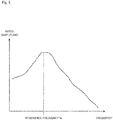
- the extraction unit 3 extracts a frequency corresponding to the peak of the ratio as a feature of the vibrations.
- the frequency corresponding to the peak of the ratio is regarded as a resonance frequency as shown in FIG. 5.
- FIG. 5 is a diagram illustrating the resonance frequency.
- the resonance frequency is used because the resonance frequency changes according to soil conditions and it is possible to estimate soil conditions by using such a relationship between the soil conditions and the resonance frequency.
- a feature of vibrations is not limited to that described above, and a feature other than the resonance frequency may be employed as a feature of vibrations.
- information indicating the sharpness (the Q factor) of the resonance frequency curve may be employed as a feature of vibrations instead of the resonance frequency.
- Information indicating the sharpness of the resonance frequency curve is used because the sharpness of the resonance frequency curve changes according to soil conditions and it is possible to estimate soil conditions by using such a relationship between the soil conditions and the sharpness of the resonance frequency curve.
- the estimation unit 4 estimates the soil conditions by referencing soil estimation information, using the extracted feature. Specifically, the estimation unit 4 first acquires the feature from the extraction unit 3. Next, using the acquired feature, the estimation unit 4 references soil estimation information, in which features and soil conditions are associated with each other, to estimate soil conditions. Soil estimation information has been stored in a storage unit (not shown) in advance, for example.
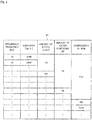
- FIG. 6 is a diagram illustrating an example of a data structure of soil estimation information.
- the soil estimation information 61 shown in FIG. 6 is information in which the hardness (kg/m 2 ) of soil, the amount (m/m 3 ) of roots contained in soil, the amount (%) of water contained in soil, the composition of soil, or two or more of these elements are associated with a resonance frequency (Hz), which is a feature.
- Hz resonance frequency
- the resonance frequency increases as the hardness of soil increases. This is because a hard object is resilient to an external force, and accordingly has a high resonance frequency. Also, the resonance frequency increases as the amount of roots contained in soil increases. This is because it is envisaged that the resonance frequency increases as the amount of roots increase if roots have a higher tension than soil, even though how the resonance frequency changes as the amount of roots increases depends on the type of roots and the type of soil. Another reason is that it is envisaged that the resonance frequency decreases as the amount of water contained in soil increases. This is because it is envisaged that fluids such as water generally have a lower tension than soil. Also, the resonance frequency varies according to the composition of soil (e.g. clay, mud, or sand).
- the composition of soil e.g. clay, mud, or sand
- the resonance frequency is 10 Hz
- the combination of a hardness of 2000 (kg/m 2 ), an amount of roots of 1.0 (m/m 3 ), and an amount of water contained of 30 (%), and clay may be envisaged in addition to the combination of a hardness of 1000 (kg/m 2 ), an amount of roots of 1.0 (m/m 3 ), an amount of water contained of 10 (%), and clay.
- factors other than the hardness may be determined by specifying the amount of roots, the amount of water, and the composition of soil, using a crop simulation, a moisture sensor, a soil analysis, and so on, and the hardness may be determined based on the results of specification.
- the number of dimensions may be increased regarding the features of vibrations.
- the Q factor of the resonance frequency may also be specified as a feature amount, or a plurality of resonance frequencies may be measured, for example. As a result, even if different factors result in the same resonance frequency, it is possible to distinguish between soils that are in different conditions.
- the output information generation unit 26 causes the output device 23 to output soil conditions corresponding to the soil layer. Specifically, the output information generation unit 26 first acquires information indicating soil conditions, from the estimation unit 4. Next, the output information generation unit 26 generates output information that is to be used to cause the output device 23 to output soil conditions corresponding to a soil layer, using information regarding the selected soil layer and the soil conditions corresponding to the soil layer. Thereafter, the output information generation unit 26 outputs the generated output information to the output device 23, and causes the output device 23 to output the soil conditions corresponding to the soil layer.
- FIG. 7 is a diagram illustrating example operations of the soil condition estimation apparatus.
- FIGS. 2 to 6 are referenced as appropriate.
- a soil condition estimation method is performed through operations of the soil condition estimation apparatus. Therefore, a description of a soil condition estimation method according to the present exemplary embodiment is substituted by the following description of operations of the soil condition estimation apparatus.
- step A1 the control unit 24 controls the vibrator 21 to apply vibrations to soil. Specifically, in step A1, the control unit 24 transmits vibration setting information, which is used to set the vibration force and the vibration frequency, to the vibrator 21. Thereafter, the vibrator 21 causes the soil to vibrate, based on the received vibration setting information.
- vibration setting information which is used to set the vibration force and the vibration frequency
- step A2 the collecting unit 25 collects pieces of vibration information measured by the vibration meter 22 from soil. Specifically, in step A2, the collecting unit 25 first collects pieces of vibration information from the vibration meter 22 in time series. Next, the collecting unit 25 outputs the pieces of vibration information thus collected to the selection unit 2. Also, the collecting unit 25 stores the pieces of vibration information in a storage unit (not shown).
- step A3 the selection unit 2 selects, by using the propagation time that vibrations take to propagate through soil, vibrations measured from soil, according to the depth of soil. That is to say, in step A3, the selection unit 2 selects a piece of vibration information corresponding to the subject soil layer from among the pieces of vibration information collected by the collecting unit 25, based on the propagation time of vibrations corresponding to the depth of the subject soil (soil layer).
- the selection unit 2 first acquires the piece of vibration information from the collecting unit 25.
- the selection unit 2 calculates a selection time period from the propagation time corresponding to the subject soil layer. For example, in a case in which the piece of vibration information corresponding to the soil layer 1 is selected, the calculation of a selection time period is performed using the propagation time T1 corresponding to the soil layer 1, to calculate the period of time (selection time period) from when vibrations are applied by the vibrator 21 to soil to when the vibrations 1 that have been reflected by the soil layer 1 can be measured by the vibration meter 22, using the propagation time T1 corresponding to the soil layer 1.
- the selection unit 2 selects the piece of vibration information corresponding to the subject soil layer from among the acquired pieces of vibration information, using the selection time period. That is to say, the selection unit 2 selects the piece of vibration information measured during the selection time period corresponding to the subject soil layer.
- the selection time period ts1 corresponding to the soil layer 1 is a period of time from the point in time te1-a1, which is earlier than the point in time te1, to the point in time te1+b1, at which vibrations reflected by the soil layer 1 are no longer detectable.
- the time al (start information) and the time b1 (end information) can be obtained through experiments or simulations, for example.
- the selection time periods ts2, ts3, and so on are respectively calculated for the soil layers 2, 3, and so on other than the soil layer 1.
- the above-described propagation time, start information, and end information regarding each soil layer are stored in the storage unit in advance such that the propagation time, start information, and end information are associated with each other as shown in the selection time period generation information 41 in FIG. 4 .
- soil layers, propagation times, and selection time periods may be stored in the storage unit in advance in association with each other as shown in the selection time period generation information 42 in FIG. 4 .
- step A4 the extraction unit 3 extracts a feature of the selected vibrations.
- features of vibrations include a resonance frequency.
- step A4 the extraction unit 3 first acquires a piece of reference vibration information (the input value x(t)), which serves as a reference corresponding to the vibrations applied by the vibrator 21 to soil, and a piece of vibration information (the output value y(t)) corresponding to the soil layer selected by the selection unit 2.
- Reference vibration information is obtained through experiments or simulations, and is stored in the storage unit.
- reference vibration information may be generated based on vibrations of soil measured using a vibration meter other than the vibration meter 22 immediately after vibrations have been applied to soil.
- step A4 the extraction unit 3 calculates a function that expresses a relationship between the input value x(t) and the output value y(t) corresponding to the input value x(t). For example, the extraction unit 3 calculates a transfer function G(s).
- the transfer function G(s) is expressed as a ratio (Y(s)/X(s)) between the input value X(s) and the output value Y(s), which are obtained by applying Laplace transform to the input value x(t) and the output value y(t).
- the ratio expresses how vibrations are transferred to the soil.
- step A4 using a relationship between the frequency corresponding to the vibrations (the frequency that has been swept) and the ratio (the amplitude), the extraction unit 3 extracts a frequency corresponding to the peak of the ratio as a feature of the vibrations (a resonance frequency).
- a resonance frequency For example, the frequency corresponding to the peak of the ratio (the amplitude) is regarded as a resonance frequency as shown in FIG. 5.
- FIG. 5 is a diagram illustrating the resonance frequency.
- the resonance frequency is used because the resonance frequency changes according to soil conditions and it is possible to estimate soil conditions by using such a relationship between the soil conditions and the resonance frequency.
- a feature of vibrations is not limited to that described above, and a feature other than the resonance frequency may be employed as a feature of vibrations.
- step A5 the control unit 24 determines whether or not the vibrator 21 has been caused to apply vibrations at all of the preset vibration frequencies. If the vibrator 21 has been caused to apply vibrations at all of the vibration frequencies (step A5: Yes), the control unit 24 performs processing to estimate soil conditions in step A7. If there is any vibration frequency at which vibrations have not been applied (step A5: No), the control unit 24 changes the vibration frequency in step A6. That is to say, the current vibration frequency is changed so as to be swept.
- step A7 using the feature, the estimation unit 4 references soil estimation information, in which features and soil conditions are associated with each other, to estimate soil conditions. Specifically, in step A7, the estimation unit 4 first acquires the feature from the extraction unit 3. Next, using the acquired feature, the estimation unit 4 references soil estimation information, in which features and soil conditions are associated with each other, to estimate soil conditions. Soil estimation information has been stored in a storage unit (not shown) in advance, for example.
- Soil estimation information is information in which the hardness (kg/m 2 ) of soil, the amount (m/m 3 ) of roots contained in soil, the amount (%) of water contained in soil, the composition of soil, or two or more of these elements are associated with a feature (e.g. a resonance frequency (Hz)).
- a feature e.g. a resonance frequency (Hz)
- step A8 the output information generation unit 26 generates output information, using the estimated soil conditions, and outputs the output information to the output device 23.
- the output information generation unit 26 first acquires information indicating soil conditions, from the estimation unit 4. Next, the output information generation unit 26 generates output information that is to be used to cause the output device 23 to output soil conditions corresponding to a soil layer, using information regarding the selected soil layer and the soil conditions corresponding to the soil layer. Thereafter, the output information generation unit 26 outputs the generated output information to the output device 23, and causes the output device 23 to output the soil conditions corresponding to the soil layer.
- the present exemplary embodiment it is only required that measurement can be performed as shown in the gain diagram in FIG. 5 . Therefore, it is possible to perform integration using a weak continuous wave.
- the vibrator 21 by intermittently applying weak vibrations to soil, or continuously applying vibrations to soil, it is possible to increase the S/N ratio of the vibrations that have been measured statistically. Therefore, it is possible to estimate soil conditions without damaging a ridge or the like of a soft soil such as a soil of a farm field.
- the vibration meter 22 it is unnecessary to apply a strong impact because the speed is not measured, and it is possible to provide the vibration meter 22 immediately next to the vibrator 21 to perform measurement. That is to say, with a conventional method through which the hardness is measured using the propagation speed of vibrations, it is necessary to detect a difference in speed, i.e. a difference in arrival time of vibrations. Also, it is necessary to separate the vibration source from the measurement point so that the time difference can be measured, and therefore it is necessary to apply strong vibrations.
- it is unnecessary to detect the difference in speed and it is only necessary that vibrations that have been intermittently or continuously applied to soil using the vibrator 21 are measured using the vibration meter 22, and the magnitude of the measured vibrations can be known. Therefore, it is possible to provide the vibration meter 22 immediately next to the vibrator 21 to perform measurement.
- an appropriate treatment include prompting a worker to plow soil if the soil is hard.
- a program according to an exemplary embodiment of the present invention may be a program that causes a computer to execute steps A1 to A8 shown in FIG. 7 . It is possible to realize the soil condition estimation apparatus and the coil condition estimation method according to the present exemplary embodiment by installing this program onto a computer and executing the program. If this is the case, the processor of the computer functions as the control unit 24, the collecting unit 25, the selection unit 2, the extraction unit 3, the estimation unit 4, and the output information generation unit 26, and performs processing.
- the program according to the present exemplary embodiment may be executed by a computer system that is constituted by a plurality of computers. If this is the case, for example, each computer may function as any of the control unit 24, the collecting unit 25, the selection unit 2, the extraction unit 3, the estimation unit 4, and the output information generation unit 26.
- FIG. 8 is a block diagram showing an example computer that realizes a soil condition estimation apparatus according to an exemplary embodiment of the present invention.
- a computer 110 includes a CPU 111, a main memory 112, a storage device 113, an input interface 114, a display controller 115, a data reader/writer 116, and a communication interface 117. These units are connected via bus 121 so as to be able to perform data communication with each other.
- the computer 110 may include a GPU (Graphics Processing Unit) or a FPGA (Field-Programmable Gate Array) in addition to the CPU111 or instead of the CPU111.
- the CPU111 loads a program (codes) according to the present exemplary embodiment stored in the storage device 113 to the main memory 112, and executes them in a predetermined order to perform various kinds of calculations.
- the main memory 112 is typically a volatile storage device such as a DRAM (Dynamic Random Access Memory).
- the program according to the present exemplary embodiment is provided in the state of being stored in a computer-readable recording medium 120. Note that the program according to the present exemplary embodiment may be distributed on the Internet that is connected via the communication interface 117.
- the storage device 113 includes a hard disk drive, and a semiconductor storage device such as a flash memory.
- the input interface 114 mediates data transmission between the CPU 111 and the input device 118 such as a keyboard or a mouse.
- the display controller 115 is connected to a display device 119, and controls the display of the display device 119.
- the data reader/writer 116 mediates data transmission between the CPU 111 and the recording medium 120, and reads out the program from the recording medium 120 and writes the results of processing performed in the computer 110 to the recording medium 120.
- the communication interface 117 mediates data transmission between the CPU 111 and another computer.
- the recording medium 120 include general-purpose semiconductor storage devices such as a CF(Compact Flash (registered trademark)) and a SD (Secure Digital), a magnetic recording medium such as a flexible disk, and an optical recording medium such as a CD-ROM (Compact Disk Read Only Memory).
- general-purpose semiconductor storage devices such as a CF(Compact Flash (registered trademark)) and a SD (Secure Digital)
- a magnetic recording medium such as a flexible disk
- an optical recording medium such as a CD-ROM (Compact Disk Read Only Memory).
- a soil condition estimation apparatus comprising:
- the soil condition estimation apparatus wherein the selection unit selects vibrations corresponding to the depth of a subject soil, using a selection time period corresponding to the depth of the subject soil, the selection time period being used to select vibrations corresponding to the depth of the subject soil, and being calculated based on a preset propagation time.
- the soil condition estimation apparatus according to Supplementary Note 1 or 2, wherein the propagation time is a period of time from when vibrations are applied to a ground surface of the subject soil to when the vibrations that have propagated through the soil are measured at the ground surface.
- the soil condition estimation apparatus according to any one of Supplementary Notes 1 to 3, wherein the soil estimation information is information in which the hardness of a soil, the amount of roots contained in a soil, the amount of water contained in a soil, the composition of a soil, or two or more of these elements are associated with the feature.
- a soil condition estimation method comprising:
- the soil condition estimation method according to any one of Supplementary Notes 6 to 8, wherein the soil estimation information is information in which the hardness of a soil, the amount of roots contained in a soil, the amount of water contained in a soil, the composition of a soil, or two or more of these elements are associated with the feature.
- a program recorded thereon including instructions that causes a computer to carry out:
- vibrations corresponding to the depth of a subject soil are selected using a selection time period corresponding to the depth of the subject soil, the selection time period being used to select vibrations corresponding to the depth of the subject soil, and being calculated based on a preset propagation time.
- the soil estimation information is information in which the hardness of a soil, the amount of roots contained in a soil, the amount of water contained in a soil, the composition of a soil, or two or more of these elements are associated with the feature.
- the present invention it is possible to estimate soil conditions according to the depth of soil.
- the present invention is useful in a technical field in which soil conditions need be estimated.
Landscapes
- Life Sciences & Earth Sciences (AREA)
- Physics & Mathematics (AREA)
- Chemical & Material Sciences (AREA)
- Health & Medical Sciences (AREA)
- General Physics & Mathematics (AREA)
- Analytical Chemistry (AREA)
- Biochemistry (AREA)
- General Health & Medical Sciences (AREA)
- Immunology (AREA)
- Pathology (AREA)
- Engineering & Computer Science (AREA)
- Signal Processing (AREA)
- Acoustics & Sound (AREA)
- Environmental & Geological Engineering (AREA)
- Medicinal Chemistry (AREA)
- General Life Sciences & Earth Sciences (AREA)
- Geology (AREA)
- Remote Sensing (AREA)
- Food Science & Technology (AREA)
- Mathematical Optimization (AREA)
- Algebra (AREA)
- Mathematical Analysis (AREA)
- Computer Networks & Wireless Communication (AREA)
- Mathematical Physics (AREA)
- Pure & Applied Mathematics (AREA)
- Investigation Of Foundation Soil And Reinforcement Of Foundation Soil By Compacting Or Drainage (AREA)
- Geophysics And Detection Of Objects (AREA)
- Investigating Or Analyzing Materials By The Use Of Ultrasonic Waves (AREA)
- Soil Sciences (AREA)
- Water Supply & Treatment (AREA)
- Environmental Sciences (AREA)
Applications Claiming Priority (1)
| Application Number | Priority Date | Filing Date | Title |
|---|---|---|---|
| JP2019046894A JP6705525B1 (ja) | 2019-03-14 | 2019-03-14 | 土壌状態推定装置、土壌状態推定方法、及びプログラム |
Publications (2)
| Publication Number | Publication Date |
|---|---|
| EP3709015A2 true EP3709015A2 (de) | 2020-09-16 |
| EP3709015A3 EP3709015A3 (de) | 2020-10-14 |
Family
ID=69770452
Family Applications (1)
| Application Number | Title | Priority Date | Filing Date |
|---|---|---|---|
| EP20160633.2A Ceased EP3709015A3 (de) | 2019-03-14 | 2020-03-03 | Bodenzustandbewertungsvorrichtung, bodenzustandbewertungsverfahren und programm |
Country Status (3)
| Country | Link |
|---|---|
| US (1) | US20200292517A1 (de) |
| EP (1) | EP3709015A3 (de) |
| JP (1) | JP6705525B1 (de) |
Citations (3)
| Publication number | Priority date | Publication date | Assignee | Title |
|---|---|---|---|---|
| JPH1194732A (ja) | 1997-09-19 | 1999-04-09 | Matsushita Electric Ind Co Ltd | サンプルセル及びこれを用いた旋光計、尿検査装置 |
| WO2016136213A1 (ja) | 2015-02-26 | 2016-09-01 | 日本電気株式会社 | 土質判定装置、土質判定方法及び土質判定プログラムを記憶する記録媒体 |
| JP2019046894A (ja) | 2017-08-31 | 2019-03-22 | 株式会社ケーヒン | 電子制御装置 |
Family Cites Families (9)
| Publication number | Priority date | Publication date | Assignee | Title |
|---|---|---|---|---|
| JPS5667723A (en) * | 1979-11-07 | 1981-06-08 | Naganori Sato | Measuring method for propagation velocity of vibration wave |
| JP2609108B2 (ja) * | 1987-06-11 | 1997-05-14 | 日瀝化学工業株式会社 | 道路等の構成層の層厚および層質の測定方法 |
| JPH077066B2 (ja) * | 1987-07-06 | 1995-01-30 | 日本電信電話株式会社 | 地層界面及び埋設物の探知方法及びその装置 |
| US5105650A (en) * | 1990-03-08 | 1992-04-21 | Gas Research Institute | Monitoring compaction of backfill |
| US6244102B1 (en) * | 1998-09-18 | 2001-06-12 | Dynasens Ltd. | Method and system for examination and optimal compaction of soil enbankments |
| US6536553B1 (en) * | 2000-04-25 | 2003-03-25 | The United States Of America As Represented By The Secretary Of The Army | Method and apparatus using acoustic sensor for sub-surface object detection and visualization |
| EP2972252B1 (de) * | 2013-03-14 | 2023-10-18 | Robert Ernest Troxler | Systeme und verfahren zur bodeneigenschaften- und bodenfeuchtigkeitsmessung mit einem bodendurchdringenden radar |
| JP6582344B2 (ja) * | 2015-06-23 | 2019-10-02 | 国立研究開発法人土木研究所 | 地盤構造探査方法及び地盤構造探査装置 |
| JP2018146370A (ja) * | 2017-03-06 | 2018-09-20 | 日本電気株式会社 | 土壌監視装置、土壌監視システムおよび土壌監視方法 |
-
2019
- 2019-03-14 JP JP2019046894A patent/JP6705525B1/ja active Active
-
2020
- 2020-03-03 EP EP20160633.2A patent/EP3709015A3/de not_active Ceased
- 2020-03-06 US US16/811,075 patent/US20200292517A1/en not_active Abandoned
Patent Citations (3)
| Publication number | Priority date | Publication date | Assignee | Title |
|---|---|---|---|---|
| JPH1194732A (ja) | 1997-09-19 | 1999-04-09 | Matsushita Electric Ind Co Ltd | サンプルセル及びこれを用いた旋光計、尿検査装置 |
| WO2016136213A1 (ja) | 2015-02-26 | 2016-09-01 | 日本電気株式会社 | 土質判定装置、土質判定方法及び土質判定プログラムを記憶する記録媒体 |
| JP2019046894A (ja) | 2017-08-31 | 2019-03-22 | 株式会社ケーヒン | 電子制御装置 |
Also Published As
| Publication number | Publication date |
|---|---|
| US20200292517A1 (en) | 2020-09-17 |
| JP6705525B1 (ja) | 2020-06-03 |
| JP2020148649A (ja) | 2020-09-17 |
| EP3709015A3 (de) | 2020-10-14 |
Similar Documents
| Publication | Publication Date | Title |
|---|---|---|
| JP4253435B2 (ja) | 地震動の強さ推定方法及びその装置 | |
| CN109416408B (zh) | 震中距估计装置、震中距估计方法以及计算机可读记录介质 | |
| KR102209749B1 (ko) | 지진가속도 시간이력 생성 방법 및 장치 | |
| CN104880728B (zh) | 一种用于宽带扫描的质量控制的方法以及相关装置 | |
| TW201720993A (zh) | 土質判定裝置、土質判定方法及記錄程式之記錄媒體 | |
| US12163823B2 (en) | Weight estimation apparatus, weight estimation method, and computer-readable recording medium | |
| EP3707991A1 (de) | Pflanzenüberwachungsvorrichtung, pflanzenüberwachungsverfahren und programm | |
| JP5087425B2 (ja) | 構造物の健全度診断方法 | |
| EP3709015A2 (de) | Bodenzustandbewertungsvorrichtung, bodenzustandbewertungsverfahren und programm | |
| WO2019058478A1 (ja) | 振動判定装置、振動判定方法及びプログラム | |
| CN114814951B (zh) | 一种获取快慢横波慢度的方法、装置、设备及存储介质 | |
| US20220137003A1 (en) | Structure diagnosis apparatus, structure diagnosis method, and computer-readable recording medium | |
| JP6944899B2 (ja) | 地盤構造推定方法 | |
| JP2021009071A (ja) | 杭評価方法 | |
| RU2482518C1 (ru) | Способ получения радиоголограмм подповерхностных объектов | |
| JP5541486B2 (ja) | 岩盤亀裂推定装置及び岩盤亀裂推定方法 | |
| JP2004045294A (ja) | 構造物の損傷危険度判定システムおよびプログラム | |
| KR101111685B1 (ko) | 파동장의 축적 에너지를 이용한 지하구조 영상화 장치 및 방법 | |
| JP6795049B2 (ja) | 植物監視装置、植物監視方法、及びプログラム | |
| JP7730069B2 (ja) | 加振力最適化システム、加振力最適化方法、及び演算装置 | |
| CN106842329A (zh) | 储层含油饱和度的获取方法与装置 | |
| JP7629376B2 (ja) | 探査装置、探査方法、および、探査システム | |
| JP7237346B2 (ja) | 表面波探査解析装置及び表面波探査解析方法 | |
| JP2026056290A (ja) | スライム判定装置及びスライム判定方法 | |
| JP2018146285A (ja) | 構造物の健全度評価方法及び構造物の健全度評価装置 |
Legal Events
| Date | Code | Title | Description |
|---|---|---|---|
| PUAI | Public reference made under article 153(3) epc to a published international application that has entered the european phase |
Free format text: ORIGINAL CODE: 0009012 |
|
| STAA | Information on the status of an ep patent application or granted ep patent |
Free format text: STATUS: THE APPLICATION HAS BEEN PUBLISHED |
|
| PUAL | Search report despatched |
Free format text: ORIGINAL CODE: 0009013 |
|
| AK | Designated contracting states |
Kind code of ref document: A2 Designated state(s): AL AT BE BG CH CY CZ DE DK EE ES FI FR GB GR HR HU IE IS IT LI LT LU LV MC MK MT NL NO PL PT RO RS SE SI SK SM TR |
|
| AX | Request for extension of the european patent |
Extension state: BA ME |
|
| AK | Designated contracting states |
Kind code of ref document: A3 Designated state(s): AL AT BE BG CH CY CZ DE DK EE ES FI FR GB GR HR HU IE IS IT LI LT LU LV MC MK MT NL NO PL PT RO RS SE SI SK SM TR |
|
| AX | Request for extension of the european patent |
Extension state: BA ME |
|
| RIC1 | Information provided on ipc code assigned before grant |
Ipc: G01N 33/24 20060101AFI20200904BHEP Ipc: G01H 1/00 20060101ALI20200904BHEP |
|
| STAA | Information on the status of an ep patent application or granted ep patent |
Free format text: STATUS: REQUEST FOR EXAMINATION WAS MADE |
|
| 17P | Request for examination filed |
Effective date: 20210414 |
|
| RBV | Designated contracting states (corrected) |
Designated state(s): AL AT BE BG CH CY CZ DE DK EE ES FI FR GB GR HR HU IE IS IT LI LT LU LV MC MK MT NL NO PL PT RO RS SE SI SK SM TR |
|
| STAA | Information on the status of an ep patent application or granted ep patent |
Free format text: STATUS: EXAMINATION IS IN PROGRESS |
|
| 17Q | First examination report despatched |
Effective date: 20220228 |
|
| STAA | Information on the status of an ep patent application or granted ep patent |
Free format text: STATUS: THE APPLICATION HAS BEEN REFUSED |
|
| 18R | Application refused |
Effective date: 20230903 |