EP3708935B1 - Verfahren zur befestigung eines einbauhaushaltgeräts an ein möbelstück - Google Patents
Verfahren zur befestigung eines einbauhaushaltgeräts an ein möbelstück Download PDFInfo
- Publication number
- EP3708935B1 EP3708935B1 EP19000125.5A EP19000125A EP3708935B1 EP 3708935 B1 EP3708935 B1 EP 3708935B1 EP 19000125 A EP19000125 A EP 19000125A EP 3708935 B1 EP3708935 B1 EP 3708935B1
- Authority
- EP
- European Patent Office
- Prior art keywords
- furniture
- adhesive surface
- built
- lateral wall
- refrigerator
- Prior art date
- Legal status (The legal status is an assumption and is not a legal conclusion. Google has not performed a legal analysis and makes no representation as to the accuracy of the status listed.)
- Active
Links
Images




Classifications
-
- F—MECHANICAL ENGINEERING; LIGHTING; HEATING; WEAPONS; BLASTING
- F25—REFRIGERATION OR COOLING; COMBINED HEATING AND REFRIGERATION SYSTEMS; HEAT PUMP SYSTEMS; MANUFACTURE OR STORAGE OF ICE; LIQUEFACTION SOLIDIFICATION OF GASES
- F25D—REFRIGERATORS; COLD ROOMS; ICE-BOXES; COOLING OR FREEZING APPARATUS NOT OTHERWISE PROVIDED FOR
- F25D23/00—General constructional features
- F25D23/10—Arrangements for mounting in particular locations, e.g. for built-in type, for corner type
-
- F—MECHANICAL ENGINEERING; LIGHTING; HEATING; WEAPONS; BLASTING
- F16—ENGINEERING ELEMENTS AND UNITS; GENERAL MEASURES FOR PRODUCING AND MAINTAINING EFFECTIVE FUNCTIONING OF MACHINES OR INSTALLATIONS; THERMAL INSULATION IN GENERAL
- F16B—DEVICES FOR FASTENING OR SECURING CONSTRUCTIONAL ELEMENTS OR MACHINE PARTS TOGETHER, e.g. NAILS, BOLTS, CIRCLIPS, CLAMPS, CLIPS OR WEDGES; JOINTS OR JOINTING
- F16B12/00—Jointing of furniture or the like, e.g. hidden from exterior
- F16B12/04—Non-loosenable joints for non-metal furniture parts, e.g. glued
Definitions
- the present invention relates to the fixing of a built-in domestic appliance inside a furniture.
- the present invention finds advantageous application in the fixing of a built-in refrigerator inside a furniture, to which the following treatment will make explicit reference without losing its generality.
- the built-in refrigerators i.e. the refrigerators intended to be fixed inside a kitchen furniture, are fixed to the furniture by means of screw fixing systems.
- the operator in order to connect the door of the built-in refrigerator to the door of the kitchen furniture, the operator must screw a guide profile (typically with a "T" cross section) to the door of the kitchen furniture by means of a third plurality of fixing screws, and he must fix a sled (typically with a "C" cross-section) at the edge of the door of the refrigerator, after having coupled the sled to the guide profile, so that the sliding coupling between the sled and the guide profile allows to open and close simultaneously the door of the kitchen furniture and the door of the built-in refrigerator.
- a guide profile typically with a "T” cross section
- Screw fixing systems require the use of screwdrivers (often of different shape and size since the fixing screws are not all the same) and they also require a certain skill in handling the screwdrivers, since at least some of the fixing screws are arranged in relatively uncomfortable position to reach. Moreover, when a built-in refrigerator is removed from a furniture (for example, to perform a repair operation), there is a (high) risk of losing one or more fixing screws, especially when the built-in refrigerator is reassembled in the furniture only after some days.
- the object of the present invention is to provide a method for fixing a built-in domestic appliance inside a furniture which are free from the drawbacks described above and which, in particular, allow to simplify and speed up the fixing, i.e. assembly, and the separation, i.e. dismantling, of a built-in domestic appliance inside a furniture.
- the fixing system includes:
- the method for fixing a built-in domestic appliance to a furniture includes the step of:
- the first removable protective film and/or the second removable protective film has a first graspable removal flap which extends beyond the first adhesive surface and/or the second adhesive surface to protrude outside the first lateral wall of the built-in domestic appliance when the built-in domestic appliance is inserted inside the furniture.
- the third removable protective film and/or the fourth removable protective film has a second graspable removal flap which extends beyond the third adhesive surface and/or the fourth adhesive surface to protrude outside the second lateral wall of the built-in domestic appliance when the built-in domestic appliance is inserted inside the furniture.
- the first fixing element comprises a first separable/joinable several times connecting device which is interposed between the first adhesive surface and the second adhesive surface.
- the second fixing element comprises a second separable/joinable several times connecting device which is interposed between the third adhesive surface and the fourth adhesive surface.
- the first separable/joinable several times connecting device comprises a first body which supports the first adhesive surface and a second body which supports the second adhesive surface and is connected to the first body in such a way to be separable/joinable several times.
- the second separable/joinable several times connecting device comprises a third body which supports the third adhesive surface and a fourth body which supports the fourth adhesive surface and is connected to the third body in such a way to be separable/joinable several times.
- each separable connecting device uses a closure system with micro-slots and micro-hooks.
- the second fixing element comprises a spacer group which is interposed between the third adhesive surface and the fourth adhesive surface and has an adjustable thickness to vary the distance between the third adhesive surface and the fourth adhesive surface.
- the spacer group comprises: an inner plate which is connected to the third adhesive surface; an outer plate which is connected to the fourth adhesive surface; a cylindrical seat solidally constrained to the inner plate or the external plate; and an adjustment element which is inserted in the cylindrical seat, is rotatably mounted to the outer plate or to the inner plate, and is adapted to be rotated relative to the cylindrical seat to vary the distance between the two plates.
- the cylindrical seat is threaded and the adjustment element is threaded and screwed into the cylindrical seat.
- the two plates are connected to each other by means of an "U" shaped flexible connecting element.
- the second fixing element comprises a removable reference plate which extends in a direction orthogonal to the third and fourth adhesive surfaces to abut against an inner edge of the door of the furniture when the second fixing element is resting on the second lateral wall of the furniture so as to allow correct arrangement of the second fixing element.
- the fixing system comprises: a guide profile; a third fixing element comprising a fifth adhesive surface suitable to be glued to the door of the furniture, a sixth adhesive surface parallel and opposite to the fifth adhesive surface and suitable to be glued to the guide profile, and a fifth removable protective film which initially covers the fifth adhesive surface; and a sled which can be fixed to a door of the built-in domestic appliance and shaped to can slidably be coupled to the guide profile.
- the third fixing element comprises a third separable/joinable several times connecting device which is interposed between the fifth adhesive surface and the sixth adhesive surface.
- the third separable/joinable several times connecting device comprises a fifth body which supports the fifth adhesive surface and a sixth body which supports the sixth adhesive surface and is connected to the fifth body in such a way to be separable/joinable several times.
- the method for fixing a built-in domestic appliance to a furniture comprising, after gluing the fourth adhesive surface of the second fixing element to the second lateral wall of the furniture and before inserting the built-in domestic appliance into the furniture, the further step of adjusting the thickness of the spacer group so that, once the built-in domestic appliance has been inserted into the furniture, the first lateral wall of the built-in domestic appliance to be contact with the first adhesive surface and the second lateral wall of the built-in appliance to be in contact with the third adhesive surface.
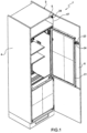
- the number 1 indicates as whole a fixing system for a built-in refrigerator 2 inside a kitchen furniture 3.
- the furniture 3 has a lateral wall 4, a lateral wall 5 which is parallel and opposite to the lateral wall 4, and a door 6 which is hinged to the lateral wall 5.
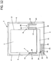
- the fixing system 1 illustrated in the attached figures comprises a fixing element 7 (shown in figure 2 ) and a fixing element 8 (shown in figures 3 and 4 ).
- the fixing element 7 illustrated in figure 2 is suitable to fix a lateral wall 9 of the built-in refrigerator 2 to the lateral wall 4 of the furniture 3; the fixing element 7 has an adhesive surface 10 which, in use, is glued to a lateral wall 9 of the built-in refrigerator 2 and an adhesive surface 11, which is parallel and opposite the adhesive surface 10, and which, in use, is glued to the lateral wall 4 of the furniture 3.
- the fixing element 8 illustrated in figures 3 and 4 is suitable, instead, to fix a lateral wall 12 of the built-in refrigerator 2 to the lateral wall 5 of the furniture 3;
- the fixing element 8 has an adhesive surface 13 which, in use, is glued to the lateral wall 12 of the built-in refrigerator 2 and an adhesive surface 14, which is parallel and opposite to the adhesive surface 13, and which, in use, is glued to the lateral wall 5 of the furniture 3.
- the adhesive surfaces 10-11 and 13-14 are initially covered by respective removable protective films 15, 16, 17 and 18: a removable protective film 15 is arranged on the adhesive surface 10; a removable protective film 16 is arranged on the adhesive surface 11; a removable protective film 17 is arranged on the adhesive surface 13, and a removable protective film 18 is arranged on the adhesive surface 14.
- the removable protective film 15 has a graspable removal flap 19 extending beyond the adhesive surface 10 so that, when the adhesive surface 10 is resting on the lateral wall 9 of the built-in refrigerator 2, the graspable removal flap 19 protrudes outwardly from the lateral wall 9 of the built-in refrigerator 2 (and therefore it can be easily grasped by an installer to be pulled, so as to remove the removable protective film 15).
- the removable protective film 17 preferably has a graspable removal flap 20 extending beyond the adhesive surface 13 so that, when the adhesive surface 13 is resting on the lateral wall 12 of the 2 built-in refrigerator 2, the graspable removal flap 20 protrudes outwardly from the lateral wall 12 of the 2 built-in refrigerator 2 (and therefore it can be easily grasped by an installer to be pulled so as to remove the removable protective film 17).
- the installer who fixes the built-in refrigerator 2 in the furniture 3 can easily remove the removable protective films 15 and 17, by pulling the respective graspable removal flaps 19 and 20, after inserting the built-in refrigerator 2 inside of the furniture 3 in the correct position.
- each removable protective film 15 and 17 is made of a low-friction smooth material so as to permit the built-in refrigerator 2 to slide between the removable protective films 15 and 17, reducing friction to a minimum.
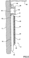
- the fixing system 1 shown in the attached figures preferably comprises a guide profile 22 intended to be fixed to the door 6 of the furniture 2 through a fixing element 23 (shown in figures 6, 7 and 10 ) and a sled 24 intended to be fixed to the door 21 of the built-in refrigerator 2 and shaped so that it can be slidably coupled to the guide profile 22.
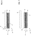
- the fixing element 23 preferably comprises an adhesive surface 25 intended to be glued to the door 6 of the furniture 3 and an adhesive surface 26, which is parallel and opposite the adhesive surface 25, and is intended to be glued to the guide profile 22.
- the adhesive surface 26 of the fixing element 23 is glued from the beginning to the guide profile 22 (i.e. the guide profile 22 is already glued to the fixing element 23 and therefore this gluing operation must not be carried out by the installer); in this case, the fixing element 23 comprises a single removable protective film 27, which is arranged to initially cover the adhesive surface 25, i.e. before the adhesive surface 25 is glued to the door 6 of the furniture 3.
- the fixing element 23 is apart from the guide profile 22 and therefore the fixing element 23 comprises a further removable protective film 28 to initially cover the adhesive surface 26, i.e. before the adhesive surface 26 is glued to the guide profile 22.
- the fixing element 7 preferably comprises a separable/joinable several times connecting device 29 which is interposed between the adhesive surface 10 and the adhesive surface 11.
- the fixing element 8 comprises a separable/joinable several times connecting device 30 which is interposed between the adhesive surface 13 and the adhesive surface 14.
- the fixing element 23 preferably comprises a separable/joinable several times connecting device 31 which is interposed between the adhesive surface 25 and the adhesive surface 26.
- the connecting devices 29, 30 and 31, advantageously, allow to separate and subsequently join together, respectively, the adhesive surfaces 10 and 11, the adhesive surfaces 13 and 14, and the adhesive surfaces 25 and 26, thus allowing the disassembly of the built-in refrigerator 2 from the furniture 3 and the subsequent re-assembly of the built-in refrigerator 2 into the furniture 3.
- the separable/joinable several times connecting device 29 preferably comprises a body 32 which supports the adhesive surface 10, and a body 33 which supports the adhesive surface 11 and is connected to the body 32 in such a way to be separable/joinable several times, so that every time you want to separate the built-in refrigerator 2 from the furniture 3 (i.e. you want to separate the lateral wall 9 of the built-in refrigerator 2 from the lateral wall 4 of the furniture 3) you just need to separate the two bodies 32 and 33, for example by inserting a thin tool between the bodies 32 and 33 of the connecting device 29 so that the thin tool act as a lever for applying a separating force to the bodies 32 and 33.
- the separable/joinable several times connection device 30 preferably comprises a body 34 which supports the adhesive surface 13 and a body 35 which supports the adhesive surface 14 and is connected to the body 34 in such a way to be separable/joinable several times, so that whenever you want to separate the built-in refrigerator 2 from the furniture 3 (i.e. you want to separate the lateral wall 12 of the built-in refrigerator 2 from the lateral wall 5 of the furniture 3) you just need to separate the two bodies 34 and 35, for example by inserting a thin tool between the bodies 34 and 35 of the connecting device 30 so that the thin tool act as a lever for applying a separating force to the bodies 34 and 35.
- the separable/joinable several times device 31 preferably comprises a body 36 which supports the adhesive surface 25 and a body 37 which supports the adhesive surface 26 and is connected to the body 36 in such a way to be separable/joinable several times, so that whenever you want to separate the guide profile 22 from the door 6 of the furniture 3 (or if you want to separate the door 21 of the built-in refrigerator 2 from the door 6 of the piece of furniture 3) you just need to separate the two bodies 36 and 37 between them, for example by inserting a thin tool between the bodies 36 and 37 of the connecting device 31 so that the thin tool act as a lever for applying a separating force to the bodies 36 and 37.
- the connecting devices 29, 30 and 31 use a closing system with micro-slots and micro-hooks to keep the respective bodies 32-37 joined together (i.e. in a body 32-37 are present a plurality of micro-slots while in the other body 32-37 there are a plurality of micro-hooks, which couple mechanically and separably with respective micro-slots) .
- the bodies 32-37 of the connecting devices 29, 30 and 31 may be made of fabric of polymeric material, or of natural fibres.
- the body 32, the body 34 and the body 36 could be made by intertwining the constituent fabric so as to define a first weft
- the body 33, the body 35 and the body 37 could be made by intertwining the same fabric according to a second weft, which is different from the first weft and is configured so as to be suitable to be coupled and decoupled with the first weft several times, so as to be suitable to easily separate/join several times the bodies 32 and 33, 34 and 35, 36 and 37 among them.
- the bodies of the connecting devices 29, 30 and 31 can be made of a non-woven fabric, for example made of polymeric material or alternatively natural fibres, configured to be separable and joinable several times.
- the bodies 32 and 33 of the connecting device 29, the bodies 34 and 35 of the connecting device 30 and the bodies 36 and 37 of the connecting device 31 could be made in such a way as to form a single a layer made, for example, of non-woven fabric, or fabric, which can be separated and reattached several times.
- the fixing element 8 preferably further comprises a spacer assembly 38 which is interposed between the adhesive surface 13 and the adhesive surface 14 and which has an adjustable thickness to vary the distance between the adhesive surfaces 13 and 14.
- the spacer assembly 38 allows the adhesive surfaces 13 and 14 to be moved apart or brought together so as to compensate any small differences in width between the furniture 3 and the built-in refrigerator 2 and so as that the fixing element 8 have a thickness greater than the hinges 39 (partially shown in Figure 1 ), arranged on the lateral wall 5 of the furniture 3 (i.e. the hinges 39 by means of which the door 6 of the furniture 3 is connected to the lateral wall 5) in order to ensure that once the built-in refrigerator 2 is inserted in the furniture 3, the built-in refrigerator 2 comes into contact with the removable protective film 17 or, after the removable protective film 17 has been removed, with the adhesive surface 13. Indeed, if this were not the case, the fixing between the built-in refrigerator 2 and the furniture 3 could be compromised.
- the spacer assembly 38 shown in figure 5 comprises an inner plate 40, which is connected to the adhesive surface 13 (by means of the interposing of the connecting device 30) and carries a cylindrical seat 41, and an outer plate 42, which is connected to the adhesive surface 14 and carries an adjustment element 43 which is rotatably mounted on the outer plate 42.
- the inner plate 40 and the outer plate 42 are arranged in such a way that the cylindrical seat 41 rotatably receives the adjustment element 43 so that by rotating the adjustment element 43 inside the cylindrical seat 41 it is possible to vary the distance between the two plates 40 and 42.
- the spacer assembly 38 shown in figure 5 has a threaded cylindrical seat 41 and a threaded adjusting element 43 screwed into the cylindrical seat 41 so that by screwing or unscrewing the adjustment element 43 with respect to the cylindrical seat 41 there is a forward or a retraction of the adjustment element 43, and therefore of the external plate 42 to which said adjustment element 43 is connected, with respect to the internal plate 40.
- the two plates 40 and 42 are connected to each other by means of an "U" shaped flexible connecting element 44.
- This flexible connecting element 44 serves to keep the two plates 40 and 42 constrained to each other, so that in the case that the adjusting element 43 is rotated too much until to cause, unintentionally, the decouple of the adjusting element 43 with respect to the cylindrical seat 41, the plates 40 and 42 remain bound to each other.
- the adjustment element 43 preferably has a maneuvering portion 45 (typically provided with a slit wide enough to be engaged also by a coin) for screwing and unscrewing the adjustment element 43.
- this maneuvering portion 45 is arranged to be accessible even when the fixing element 8 is fixed to the lateral wall 5 of the furniture 3.
- the cylindrical seat 41 could solidaly constrained to the outer plate 42 and the adjusting element 43 could be mounted rotatable to the inner plate 40.
- the fixing element 8 shown in figure 3, 4 and 5 preferably comprises a removable reference plate 46 which extends in a direction orthogonal to the adhesive surfaces 13 and 14 to abut against an inner edge 47 (shown in Figure 1 )of the door 6 of the furniture 3 when the fixing element 8 is resting against the lateral wall 5 of the piece of furniture 3.
- the removable reference plate 46 is connected to the fixing element 8 by interposition of a weakening portion 48, so as to facilitate the removal of the reference plate 46, once the fixation device 8 has been fixed to the lateral wall 5 of the furniture 3 by means of the adhesive surface 14.
- the built-in refrigerator 2 is outside the furniture 3 and the three fixing elements 7, 8 and 23 are apart from the built-in refrigerator 2 and from the furniture 3.
- the installer removes the removable protective film 16 from the adhesive surface 11 of the fixing element 7 and then glues the adhesive surface 11 to the lateral wall 4 of the furniture 3 to firmly connect the fixing element 7 to the lateral wall 4 of the furniture 3 in a position such as to ensure that the preferred graspable removal flap 19 will protrude with respect to the lateral wall 9 of the built-in refrigerator 2 (when the built-in refrigerator 2 will be positioned inside the furniture 3).
- the installer removes the removable protective film 18 from the adhesive surface 14 of the fixing element 8 and then glues the adhesive surface 14 to the lateral wall 5 of the furniture 3 to firmly connect the fixing element 8 to the lateral wall 5 of the furniture 3 in a position such as to ensure that the preferred graspable removal flap 20 will protrude with respect to the lateral wall 12 of the built-in refrigerator 2 (when the built-in refrigerator 2 will be positioned inside the furniture 3).
- the installer in order to correctly arrange the fixing element 8 shown in figures 3, 4 and 5 to the lateral wall 5 of the furniture 3, the installer, before gluing the adhesive surface 14 to the lateral wall 5 of the furniture 3, arranges the fixing element 8 so that the removable reference plate 46 abut against the inner edge 47 of the door 6 of the furniture 3. After the adhesive surface 14 has been glued to the lateral wall 5 of the furniture 3, then the installer breaks and removes the removable reference plate 46.
- the installer adjusts, if necessary, the thickness of the fixing element 8 acting on the adjustment element 43 of the spacer assembly 38.
- the adjustment of the thickness of the fixing element 8 has the purpose of ensuring that, once the built-in refrigerator 2 has been inserted in the furniture 3, the lateral wall 9 of the built-in refrigerator 2 is in contact with the adhesive surface 10 of the fixing element 7 and that the lateral wall 12 of the built-in refrigerator 2 is in contact with the adhesive surface 13 of the fixing element 8.
- the adjustment element 43 is rotated, for example by means of a normal screwdriver or even by a coin, until the adhesive surfaces 10 and 13, still covered by the respective protective films 15 and 17, do not lie between them at a distance which is substantially equal to the distance between the walls 9 and 12 of the built-in refrigerator 2.
- the installer inserts the built-in refrigerator 2 into the furniture 3, leaving the protection films 15 and 17 in position and then making slide the walls 9 and 12 between the films 15 and 17 of protection.
- the installer removes the removable protective film 15, preferably through the graspable removal flap 19, to glue the adhesive surface 10 of the fixing element 7 to the lateral wall 9 of the built-in refrigerator 2 and removes (subsequently or formerly) the removable protective film 17, preferably by means of the graspable removal flap 20, to glue the adhesive surface 13 of the fixing element 8 to the lateral wall 12 of the built-in refrigerator 2.
- the installer When the door 21 of the built-in refrigerator 2 must also be fixed to the door 6 of the furniture 3, the installer must initially glue the adhesive surface 26 of the fixing element 23 to the guide profile 22, after removing the removable protective film 28 (obviously, if the fixing element 23 is already pre-glued to the guide profile 22, this operation is not necessary). Subsequently, the installer preferably fixes the sled 24 to the door 21 of the built-in refrigerator 2 (typically by means of a screw fixing system of known type); alternatively, the sled 24 could be already pre-mounted on the door 21 of the built-in refrigerator 2. At this point, the installer couples the guide profile 22 (which is preferably glued to the fixing element 23 and is still separated from the door 6 of the furniture 3) to the sled 24.
- the installer removes the protective film 27 from the adhesive surface 25 and he glues the adhesive surface 25 of the fixing element 23 to the door 6 of the furniture 3; this operation is performed extremely easily and quickly, by simply closing the door 6 of the furniture 3 and pressing on the door 6 so that the door 6 sticks to the adhesive surface 25 of the fixing element 23.
- the guide profile 22 has a " disposable " support system which keeps the guide profile 22 in the correct position after the guide profile 22 has been mounted on the sled 24 and before the door 6 of the furniture 3 is closed against the guide profile 22 to glue the adhesive surface 25 of the fixing element 23 to the door 6.
- any one or all of the separable connecting devices 29, 30 and 31 are not present; in this case, to separate the built-in refrigerator 2 from the furniture 3 to which the built-in refrigerator 2 is fixed is necessary to brake (cut) the fixing elements 7, 8 and 23 and to use new fixing elements 7, 8 and 23 to subsequent newly insert the built-in refrigerator 2 into the furniture 3.
- the removable protective films 15 and 17 are provided with the graspable removal flaps 19 and 20; according to other embodiments not shown, the protective films 16 and 18 are provided with respective graspable removal flaps in addition or in alternative to the graspable removal flaps 19 and 20 of the removable protective films 15 and 17 (in this case, the fixing elements 7 and 8 could be glued firstly to the built-in refrigerator 2 and then to the furniture 3 instead of being glued firstly to the furniture 3 and then to the built-in refrigerator 2).
- the built-in domestic appliance 2 which is mounted inside the furniture 3 is a refrigerator; according to other embodiments not illustrated, the built-in domestic appliance 2 which is mounted inside the furniture 3 is for example an oven, a dishwasher, or a washing machine.
- the fixing system 1 described above has numerous advantages.
- the fixing system 1 described above allows the assembly and possible subsequent disassembly of the built-in refrigerator 2 into the furniture 3 in a quickly and easy manner (even without using any tool like a screwdriver).
- the fixing method described above can be easily performed even by an unskilled user.
Landscapes
- Engineering & Computer Science (AREA)
- Chemical & Material Sciences (AREA)
- Combustion & Propulsion (AREA)
- Physics & Mathematics (AREA)
- Mechanical Engineering (AREA)
- Thermal Sciences (AREA)
- General Engineering & Computer Science (AREA)
- Connection Of Plates (AREA)
- Cabinets, Racks, Or The Like Of Rigid Construction (AREA)
- Supports Or Holders For Household Use (AREA)
Claims (1)
- Verfahren zur Befestigung eines Einbauhaushaltgeräts (2) an einem Möbelstück (3) mit einem Befestigungssystem (1), das Folgendes umfasst:
ein erstes Befestigungselement (7), umfassend eine erste Klebefläche (10), dazu geeignet, an einer ersten Seitenwand (9) des Einbauhaushaltgeräts (2) angeklebt zu werden, eine zweite Klebefläche (11) parallel und gegenüber der ersten Klebefläche (10) und dazu geeignet, an der ersten Seitenwand (4) des Möbelstücks (3) angeklebt zu werden, eine erste abnehmbare Schutzfolie (15), die zunächst die erste Klebefläche (10) bedeckt, und eine zweite abnehmbare Schutzfolie (16), die zunächst die zweite Klebefläche (11) bedeckt; und ein zweites Befestigungselement (8), umfassend eine dritte Klebefläche (13), dazu geeignet, an einer zweiten Seitenwand (12) des Einbauhaushaltgeräts (2) angeklebt zu werden, und eine vierte Klebefläche (14) parallel und gegenüber der dritten Klebefläche (13) und dazu geeignet, an der zweiten Seitenwand (5) des Möbelstücks (3) angeklebt zu werden, eine dritte abnehmbare Schutzfolie (17), die zunächst die dritte Klebefläche (13) bedeckt, und eine vierte abnehmbare Schutzfolie (18), die zunächst die vierte Klebefläche (14) bedeckt; wobei das Befestigungsverfahren die folgenden Schritte umfasst:Ankleben der zweiten Klebefläche (11) des ersten Befestigungselements (7) an der ersten Seitenwand (4) des Möbelstücks (3), indem zuerst die zweite Schutzfolie (16) entfernt wird;Ankleben der vierten Klebefläche (14) des zweiten Befestigungselements (8) an der zweiten Seitenwand (5) des Möbelstücks (3), indem zuerst die vierte Schutzfolie (18) entfernt wird;Einsetzen des Einbauhaushaltgeräts (2) in das Möbelstück (3), wobei die erste abnehmbare Schutzfolie (15) und die dritte Schutzfolie (17) in Position bleiben;Entfernen der ersten abnehmbaren Schutzfolie (15), um die erste Klebefläche (10) des ersten Befestigungselements (7) an die erste Seitenwand (9) des Einbauhaushaltgeräts (2) zu kleben; undEntfernen der dritten abnehmbaren Schutzfolie (17), um die dritte Klebefläche (13) des zweiten Befestigungselements (8) an die zweite Seitenwand (12) des Einbauhaushaltgeräts (2) zu kleben.
Priority Applications (3)
| Application Number | Priority Date | Filing Date | Title |
|---|---|---|---|
| EP19000125.5A EP3708935B1 (de) | 2019-03-13 | 2019-03-13 | Verfahren zur befestigung eines einbauhaushaltgeräts an ein möbelstück |
| EP20706782.8A EP3938723B1 (de) | 2019-03-13 | 2020-03-04 | Befestigungssystem eines einbauhaushaltsgeräts an einem möbelstück und verfahren zur befestigung eines einbauhaushaltgeräts an ein möbelstück |
| PCT/EP2020/055749 WO2020182586A1 (en) | 2019-03-13 | 2020-03-04 | Fixing system of a built-in domestic appliance to a furniture and method for fixing a built-in domestic appliance to a furniture |
Applications Claiming Priority (1)
| Application Number | Priority Date | Filing Date | Title |
|---|---|---|---|
| EP19000125.5A EP3708935B1 (de) | 2019-03-13 | 2019-03-13 | Verfahren zur befestigung eines einbauhaushaltgeräts an ein möbelstück |
Publications (2)
| Publication Number | Publication Date |
|---|---|
| EP3708935A1 EP3708935A1 (de) | 2020-09-16 |
| EP3708935B1 true EP3708935B1 (de) | 2024-12-11 |
Family
ID=65817706
Family Applications (2)
| Application Number | Title | Priority Date | Filing Date |
|---|---|---|---|
| EP19000125.5A Active EP3708935B1 (de) | 2019-03-13 | 2019-03-13 | Verfahren zur befestigung eines einbauhaushaltgeräts an ein möbelstück |
| EP20706782.8A Active EP3938723B1 (de) | 2019-03-13 | 2020-03-04 | Befestigungssystem eines einbauhaushaltsgeräts an einem möbelstück und verfahren zur befestigung eines einbauhaushaltgeräts an ein möbelstück |
Family Applications After (1)
| Application Number | Title | Priority Date | Filing Date |
|---|---|---|---|
| EP20706782.8A Active EP3938723B1 (de) | 2019-03-13 | 2020-03-04 | Befestigungssystem eines einbauhaushaltsgeräts an einem möbelstück und verfahren zur befestigung eines einbauhaushaltgeräts an ein möbelstück |
Country Status (2)
| Country | Link |
|---|---|
| EP (2) | EP3708935B1 (de) |
| WO (1) | WO2020182586A1 (de) |
Citations (3)
| Publication number | Priority date | Publication date | Assignee | Title |
|---|---|---|---|---|
| EP0718459B1 (de) * | 1994-10-25 | 2003-04-02 | Whirlpool Europe B.V. | Verfahren und Vorrichtung zum Befestigen eines Türblattes an der Gerätetür eines Einbauhaushaltgerätes |
| CN106590462A (zh) * | 2016-12-30 | 2017-04-26 | 芜湖研高粘胶新材料有限公司 | 一种无基材双面胶带 |
| CN207347501U (zh) * | 2017-06-02 | 2018-05-11 | 东华大学 | 一种易于粘贴的框型双面胶 |
Family Cites Families (7)
| Publication number | Priority date | Publication date | Assignee | Title |
|---|---|---|---|---|
| WO1990010362A1 (en) * | 1989-02-23 | 1990-09-07 | Subler Denis L | Telephone earpiece cushion |
| JP3011930B1 (ja) * | 1998-12-11 | 2000-02-21 | 積水化学工業株式会社 | 床板の施工方法 |
| KR100766108B1 (ko) * | 2004-05-21 | 2007-10-11 | 엘지전자 주식회사 | 빌트인타입 냉장고용 위치설정구조 |
| KR20110000953A (ko) * | 2009-06-29 | 2011-01-06 | 이정화 | 가전제품 또는 가구의 상부 보호용 커버 플레이트 |
| DE102010031485A1 (de) * | 2010-07-16 | 2012-01-19 | BSH Bosch und Siemens Hausgeräte GmbH | Haushaltsgerät mit einer Matte |
| JP5860685B2 (ja) * | 2011-12-06 | 2016-02-16 | 株式会社東芝 | 断熱キャビネット |
| ITVA20120038A1 (it) * | 2012-10-18 | 2014-04-19 | Whirlpool Co | Sistema di montaggio di pannelli su porte di frigoriferi da incasso |
-
2019
- 2019-03-13 EP EP19000125.5A patent/EP3708935B1/de active Active
-
2020
- 2020-03-04 WO PCT/EP2020/055749 patent/WO2020182586A1/en not_active Ceased
- 2020-03-04 EP EP20706782.8A patent/EP3938723B1/de active Active
Patent Citations (3)
| Publication number | Priority date | Publication date | Assignee | Title |
|---|---|---|---|---|
| EP0718459B1 (de) * | 1994-10-25 | 2003-04-02 | Whirlpool Europe B.V. | Verfahren und Vorrichtung zum Befestigen eines Türblattes an der Gerätetür eines Einbauhaushaltgerätes |
| CN106590462A (zh) * | 2016-12-30 | 2017-04-26 | 芜湖研高粘胶新材料有限公司 | 一种无基材双面胶带 |
| CN207347501U (zh) * | 2017-06-02 | 2018-05-11 | 东华大学 | 一种易于粘贴的框型双面胶 |
Also Published As
| Publication number | Publication date |
|---|---|
| EP3938723B1 (de) | 2024-12-11 |
| EP3708935A1 (de) | 2020-09-16 |
| WO2020182586A1 (en) | 2020-09-17 |
| WO2020182586A8 (en) | 2021-04-22 |
| EP3938723A1 (de) | 2022-01-19 |
Similar Documents
| Publication | Publication Date | Title |
|---|---|---|
| KR101712431B1 (ko) | 슬라이딩 방식의 도어 개폐장치 | |
| NO343822B1 (no) | Tettebånd av mykskum og fremgangsmåte for dets tilvirkning | |
| EP3708935A1 (de) | Befestigungssystem eines einbauhaushaltsgeräts an einem möbelstück und verfahren zur befestigung eines einbauhaushaltgeräts an ein möbelstück | |
| US11846408B2 (en) | Mountable device and method | |
| CN106438619B (zh) | 利用紧固件插入物在复合面板中的紧固件安装 | |
| US8745925B2 (en) | Coupling mechanism for sliding doors | |
| EP2772601A1 (de) | Tür mit griff | |
| US20170322189A1 (en) | Clamping device for a sample preparation | |
| WO2007106465A3 (en) | Package for holding multiple media discs and methods of making the same | |
| JP5226716B2 (ja) | 光ファイバ被覆除去装置 | |
| WO2023007350A1 (en) | A ventilated wall with rapid application system | |
| CN109901681A (zh) | 一种硬盘托架 | |
| EP2510835B1 (de) | Einrichtung zur Herstellung eines integrierten Griffes in einer bewegbaren Platte von Möbeln und bewegbare Platte mit einer solchen Einrichtung | |
| US8783992B2 (en) | Shutter repair system | |
| CN217537391U (zh) | 一种防火板稳固安装机构 | |
| JP7761931B2 (ja) | 壁紙糊付機装着用のカットテープ芯 | |
| EP2341292A1 (de) | Ofentür mit einer Kunststofftürsäule und Verfahren zur Montage besagter Kunststofftürsäule | |
| EP2977533A1 (de) | Scharnier für türen | |
| CN109158874A (zh) | 转移结构 | |
| CN108868413A (zh) | 可调节铰链装置及冰箱 | |
| AU2023903294A0 (en) | Centrifuge separator apparatus with adjustable inlet assembly | |
| CN309780863S (en) | Cassette rack | |
| AU2025904653A0 (en) | Adjustable drawer organiser with flexible side flaps and magnetic divider system | |
| AU2021903262A0 (en) | Centrifuge separator apparatus with adjustable inlet assembly | |
| CA3270480A1 (en) | Control method of the performance state of a heating system |
Legal Events
| Date | Code | Title | Description |
|---|---|---|---|
| STAA | Information on the status of an ep patent application or granted ep patent |
Free format text: STATUS: UNKNOWN |
|
| PUAI | Public reference made under article 153(3) epc to a published international application that has entered the european phase |
Free format text: ORIGINAL CODE: 0009012 |
|
| STAA | Information on the status of an ep patent application or granted ep patent |
Free format text: STATUS: THE APPLICATION HAS BEEN PUBLISHED |
|
| AK | Designated contracting states |
Kind code of ref document: A1 Designated state(s): AL AT BE BG CH CY CZ DE DK EE ES FI FR GB GR HR HU IE IS IT LI LT LU LV MC MK MT NL NO PL PT RO RS SE SI SK SM TR |
|
| AX | Request for extension of the european patent |
Extension state: BA ME |
|
| STAA | Information on the status of an ep patent application or granted ep patent |
Free format text: STATUS: REQUEST FOR EXAMINATION WAS MADE |
|
| 17P | Request for examination filed |
Effective date: 20210316 |
|
| RBV | Designated contracting states (corrected) |
Designated state(s): AL AT BE BG CH CY CZ DE DK EE ES FI FR GB GR HR HU IE IS IT LI LT LU LV MC MK MT NL NO PL PT RO RS SE SI SK SM TR |
|
| STAA | Information on the status of an ep patent application or granted ep patent |
Free format text: STATUS: EXAMINATION IS IN PROGRESS |
|
| 17Q | First examination report despatched |
Effective date: 20221222 |
|
| GRAP | Despatch of communication of intention to grant a patent |
Free format text: ORIGINAL CODE: EPIDOSNIGR1 |
|
| STAA | Information on the status of an ep patent application or granted ep patent |
Free format text: STATUS: GRANT OF PATENT IS INTENDED |
|
| RIC1 | Information provided on ipc code assigned before grant |
Ipc: A47L 15/42 20060101ALN20240903BHEP Ipc: F16B 12/04 20060101ALN20240903BHEP Ipc: C09J 7/00 20180101ALI20240903BHEP Ipc: F25D 23/10 20060101AFI20240903BHEP |
|
| INTG | Intention to grant announced |
Effective date: 20240917 |
|
| RIC1 | Information provided on ipc code assigned before grant |
Ipc: A47L 15/42 20060101ALN20240910BHEP Ipc: F16B 12/04 20060101ALN20240910BHEP Ipc: C09J 7/00 20180101ALI20240910BHEP Ipc: F25D 23/10 20060101AFI20240910BHEP |
|
| GRAS | Grant fee paid |
Free format text: ORIGINAL CODE: EPIDOSNIGR3 |
|
| GRAA | (expected) grant |
Free format text: ORIGINAL CODE: 0009210 |
|
| STAA | Information on the status of an ep patent application or granted ep patent |
Free format text: STATUS: THE PATENT HAS BEEN GRANTED |
|
| P01 | Opt-out of the competence of the unified patent court (upc) registered |
Free format text: CASE NUMBER: APP_56382/2024 Effective date: 20241016 |
|
| AK | Designated contracting states |
Kind code of ref document: B1 Designated state(s): AL AT BE BG CH CY CZ DE DK EE ES FI FR GB GR HR HU IE IS IT LI LT LU LV MC MK MT NL NO PL PT RO RS SE SI SK SM TR |
|
| REG | Reference to a national code |
Ref country code: GB Ref legal event code: FG4D |
|
| REG | Reference to a national code |
Ref country code: CH Ref legal event code: EP |
|
| REG | Reference to a national code |
Ref country code: IE Ref legal event code: FG4D |
|
| REG | Reference to a national code |
Ref country code: DE Ref legal event code: R096 Ref document number: 602019063280 Country of ref document: DE |
|
| REG | Reference to a national code |
Ref country code: LT Ref legal event code: MG9D |
|
| PG25 | Lapsed in a contracting state [announced via postgrant information from national office to epo] |
Ref country code: HR Free format text: LAPSE BECAUSE OF FAILURE TO SUBMIT A TRANSLATION OF THE DESCRIPTION OR TO PAY THE FEE WITHIN THE PRESCRIBED TIME-LIMIT Effective date: 20241211 |
|
| PG25 | Lapsed in a contracting state [announced via postgrant information from national office to epo] |
Ref country code: FI Free format text: LAPSE BECAUSE OF FAILURE TO SUBMIT A TRANSLATION OF THE DESCRIPTION OR TO PAY THE FEE WITHIN THE PRESCRIBED TIME-LIMIT Effective date: 20241211 |
|
| PG25 | Lapsed in a contracting state [announced via postgrant information from national office to epo] |
Ref country code: BG Free format text: LAPSE BECAUSE OF FAILURE TO SUBMIT A TRANSLATION OF THE DESCRIPTION OR TO PAY THE FEE WITHIN THE PRESCRIBED TIME-LIMIT Effective date: 20241211 |
|
| REG | Reference to a national code |
Ref country code: NL Ref legal event code: MP Effective date: 20241211 |
|
| PG25 | Lapsed in a contracting state [announced via postgrant information from national office to epo] |
Ref country code: ES Free format text: LAPSE BECAUSE OF FAILURE TO SUBMIT A TRANSLATION OF THE DESCRIPTION OR TO PAY THE FEE WITHIN THE PRESCRIBED TIME-LIMIT Effective date: 20241211 |
|
| PG25 | Lapsed in a contracting state [announced via postgrant information from national office to epo] |
Ref country code: NO Free format text: LAPSE BECAUSE OF FAILURE TO SUBMIT A TRANSLATION OF THE DESCRIPTION OR TO PAY THE FEE WITHIN THE PRESCRIBED TIME-LIMIT Effective date: 20250311 |
|
| PG25 | Lapsed in a contracting state [announced via postgrant information from national office to epo] |
Ref country code: LV Free format text: LAPSE BECAUSE OF FAILURE TO SUBMIT A TRANSLATION OF THE DESCRIPTION OR TO PAY THE FEE WITHIN THE PRESCRIBED TIME-LIMIT Effective date: 20241211 Ref country code: GR Free format text: LAPSE BECAUSE OF FAILURE TO SUBMIT A TRANSLATION OF THE DESCRIPTION OR TO PAY THE FEE WITHIN THE PRESCRIBED TIME-LIMIT Effective date: 20250312 |
|
| PG25 | Lapsed in a contracting state [announced via postgrant information from national office to epo] |
Ref country code: RS Free format text: LAPSE BECAUSE OF FAILURE TO SUBMIT A TRANSLATION OF THE DESCRIPTION OR TO PAY THE FEE WITHIN THE PRESCRIBED TIME-LIMIT Effective date: 20250311 |
|
| PG25 | Lapsed in a contracting state [announced via postgrant information from national office to epo] |
Ref country code: NL Free format text: LAPSE BECAUSE OF FAILURE TO SUBMIT A TRANSLATION OF THE DESCRIPTION OR TO PAY THE FEE WITHIN THE PRESCRIBED TIME-LIMIT Effective date: 20241211 |
|
| REG | Reference to a national code |
Ref country code: AT Ref legal event code: MK05 Ref document number: 1750672 Country of ref document: AT Kind code of ref document: T Effective date: 20241211 |
|
| PG25 | Lapsed in a contracting state [announced via postgrant information from national office to epo] |
Ref country code: SM Free format text: LAPSE BECAUSE OF FAILURE TO SUBMIT A TRANSLATION OF THE DESCRIPTION OR TO PAY THE FEE WITHIN THE PRESCRIBED TIME-LIMIT Effective date: 20241211 |
|
| PG25 | Lapsed in a contracting state [announced via postgrant information from national office to epo] |
Ref country code: PL Free format text: LAPSE BECAUSE OF FAILURE TO SUBMIT A TRANSLATION OF THE DESCRIPTION OR TO PAY THE FEE WITHIN THE PRESCRIBED TIME-LIMIT Effective date: 20241211 |
|
| PG25 | Lapsed in a contracting state [announced via postgrant information from national office to epo] |
Ref country code: IS Free format text: LAPSE BECAUSE OF FAILURE TO SUBMIT A TRANSLATION OF THE DESCRIPTION OR TO PAY THE FEE WITHIN THE PRESCRIBED TIME-LIMIT Effective date: 20250411 |
|
| PG25 | Lapsed in a contracting state [announced via postgrant information from national office to epo] |
Ref country code: PT Free format text: LAPSE BECAUSE OF FAILURE TO SUBMIT A TRANSLATION OF THE DESCRIPTION OR TO PAY THE FEE WITHIN THE PRESCRIBED TIME-LIMIT Effective date: 20250411 |
|
| PG25 | Lapsed in a contracting state [announced via postgrant information from national office to epo] |
Ref country code: EE Free format text: LAPSE BECAUSE OF FAILURE TO SUBMIT A TRANSLATION OF THE DESCRIPTION OR TO PAY THE FEE WITHIN THE PRESCRIBED TIME-LIMIT Effective date: 20241211 |
|
| PG25 | Lapsed in a contracting state [announced via postgrant information from national office to epo] |
Ref country code: AT Free format text: LAPSE BECAUSE OF FAILURE TO SUBMIT A TRANSLATION OF THE DESCRIPTION OR TO PAY THE FEE WITHIN THE PRESCRIBED TIME-LIMIT Effective date: 20241211 Ref country code: RO Free format text: LAPSE BECAUSE OF FAILURE TO SUBMIT A TRANSLATION OF THE DESCRIPTION OR TO PAY THE FEE WITHIN THE PRESCRIBED TIME-LIMIT Effective date: 20241211 |
|
| PG25 | Lapsed in a contracting state [announced via postgrant information from national office to epo] |
Ref country code: SK Free format text: LAPSE BECAUSE OF FAILURE TO SUBMIT A TRANSLATION OF THE DESCRIPTION OR TO PAY THE FEE WITHIN THE PRESCRIBED TIME-LIMIT Effective date: 20241211 |
|
| PG25 | Lapsed in a contracting state [announced via postgrant information from national office to epo] |
Ref country code: CZ Free format text: LAPSE BECAUSE OF FAILURE TO SUBMIT A TRANSLATION OF THE DESCRIPTION OR TO PAY THE FEE WITHIN THE PRESCRIBED TIME-LIMIT Effective date: 20241211 |
|
| PG25 | Lapsed in a contracting state [announced via postgrant information from national office to epo] |
Ref country code: SE Free format text: LAPSE BECAUSE OF FAILURE TO SUBMIT A TRANSLATION OF THE DESCRIPTION OR TO PAY THE FEE WITHIN THE PRESCRIBED TIME-LIMIT Effective date: 20241211 |
|
| REG | Reference to a national code |
Ref country code: DE Ref legal event code: R097 Ref document number: 602019063280 Country of ref document: DE |
|
| PG25 | Lapsed in a contracting state [announced via postgrant information from national office to epo] |
Ref country code: DK Free format text: LAPSE BECAUSE OF FAILURE TO SUBMIT A TRANSLATION OF THE DESCRIPTION OR TO PAY THE FEE WITHIN THE PRESCRIBED TIME-LIMIT Effective date: 20241211 |
|
| PG25 | Lapsed in a contracting state [announced via postgrant information from national office to epo] |
Ref country code: MC Free format text: LAPSE BECAUSE OF FAILURE TO SUBMIT A TRANSLATION OF THE DESCRIPTION OR TO PAY THE FEE WITHIN THE PRESCRIBED TIME-LIMIT Effective date: 20241211 |
|
| PLBE | No opposition filed within time limit |
Free format text: ORIGINAL CODE: 0009261 |
|
| STAA | Information on the status of an ep patent application or granted ep patent |
Free format text: STATUS: NO OPPOSITION FILED WITHIN TIME LIMIT |
|
| REG | Reference to a national code |
Ref country code: CH Ref legal event code: L10 Free format text: ST27 STATUS EVENT CODE: U-0-0-L10-L00 (AS PROVIDED BY THE NATIONAL OFFICE) Effective date: 20251022 |
|
| REG | Reference to a national code |
Ref country code: CH Ref legal event code: H13 Free format text: ST27 STATUS EVENT CODE: U-0-0-H10-H13 (AS PROVIDED BY THE NATIONAL OFFICE) Effective date: 20251023 |
|
| PG25 | Lapsed in a contracting state [announced via postgrant information from national office to epo] |
Ref country code: LU Free format text: LAPSE BECAUSE OF NON-PAYMENT OF DUE FEES Effective date: 20250313 |
|
| 26N | No opposition filed |
Effective date: 20250912 |
|
| GBPC | Gb: european patent ceased through non-payment of renewal fee |
Effective date: 20250313 |
|
| REG | Reference to a national code |
Ref country code: BE Ref legal event code: MM Effective date: 20250331 |
|
| PG25 | Lapsed in a contracting state [announced via postgrant information from national office to epo] |
Ref country code: GB Free format text: LAPSE BECAUSE OF NON-PAYMENT OF DUE FEES Effective date: 20250313 |
|
| PG25 | Lapsed in a contracting state [announced via postgrant information from national office to epo] |
Ref country code: FR Free format text: LAPSE BECAUSE OF NON-PAYMENT OF DUE FEES Effective date: 20250331 |
|
| PG25 | Lapsed in a contracting state [announced via postgrant information from national office to epo] |
Ref country code: BE Free format text: LAPSE BECAUSE OF NON-PAYMENT OF DUE FEES Effective date: 20250331 |
|
| PG25 | Lapsed in a contracting state [announced via postgrant information from national office to epo] |
Ref country code: CH Free format text: LAPSE BECAUSE OF NON-PAYMENT OF DUE FEES Effective date: 20250331 |
|
| PG25 | Lapsed in a contracting state [announced via postgrant information from national office to epo] |
Ref country code: IE Free format text: LAPSE BECAUSE OF NON-PAYMENT OF DUE FEES Effective date: 20250313 |
|
| PGFP | Annual fee paid to national office [announced via postgrant information from national office to epo] |
Ref country code: DE Payment date: 20260320 Year of fee payment: 8 |
|
| PGFP | Annual fee paid to national office [announced via postgrant information from national office to epo] |
Ref country code: IT Payment date: 20260320 Year of fee payment: 8 |
|
| PGFP | Annual fee paid to national office [announced via postgrant information from national office to epo] |
Ref country code: TR Payment date: 20260302 Year of fee payment: 8 |