EP3708848B1 - Radialverdichter und turbolader mit dem radialverdichter - Google Patents
Radialverdichter und turbolader mit dem radialverdichter Download PDFInfo
- Publication number
- EP3708848B1 EP3708848B1 EP17930425.8A EP17930425A EP3708848B1 EP 3708848 B1 EP3708848 B1 EP 3708848B1 EP 17930425 A EP17930425 A EP 17930425A EP 3708848 B1 EP3708848 B1 EP 3708848B1
- Authority
- EP
- European Patent Office
- Prior art keywords
- passage
- scroll
- wall surface
- rotational axis
- diffuser
- Prior art date
- Legal status (The legal status is an assumption and is not a legal conclusion. Google has not performed a legal analysis and makes no representation as to the accuracy of the status listed.)
- Active
Links
Images


Classifications
-
- F—MECHANICAL ENGINEERING; LIGHTING; HEATING; WEAPONS; BLASTING
- F04—POSITIVE - DISPLACEMENT MACHINES FOR LIQUIDS; PUMPS FOR LIQUIDS OR ELASTIC FLUIDS
- F04D—NON-POSITIVE-DISPLACEMENT PUMPS
- F04D17/00—Radial-flow pumps, e.g. centrifugal pumps; Helico-centrifugal pumps
- F04D17/08—Centrifugal pumps
- F04D17/10—Centrifugal pumps for compressing or evacuating
-
- F—MECHANICAL ENGINEERING; LIGHTING; HEATING; WEAPONS; BLASTING
- F02—COMBUSTION ENGINES; HOT-GAS OR COMBUSTION-PRODUCT ENGINE PLANTS
- F02B—INTERNAL-COMBUSTION PISTON ENGINES; COMBUSTION ENGINES IN GENERAL
- F02B39/00—Component parts, details, or accessories relating to, driven charging or scavenging pumps, not provided for in groups F02B33/00 - F02B37/00
-
- F—MECHANICAL ENGINEERING; LIGHTING; HEATING; WEAPONS; BLASTING
- F04—POSITIVE - DISPLACEMENT MACHINES FOR LIQUIDS; PUMPS FOR LIQUIDS OR ELASTIC FLUIDS
- F04D—NON-POSITIVE-DISPLACEMENT PUMPS
- F04D29/00—Details, component parts, or accessories
- F04D29/40—Casings; Connections of working fluid
- F04D29/42—Casings; Connections of working fluid for radial or helico-centrifugal pumps
- F04D29/4206—Casings; Connections of working fluid for radial or helico-centrifugal pumps especially adapted for elastic fluid pumps
- F04D29/4226—Fan casings
- F04D29/4233—Fan casings with volutes extending mainly in axial or radially inward direction
-
- F—MECHANICAL ENGINEERING; LIGHTING; HEATING; WEAPONS; BLASTING
- F04—POSITIVE - DISPLACEMENT MACHINES FOR LIQUIDS; PUMPS FOR LIQUIDS OR ELASTIC FLUIDS
- F04D—NON-POSITIVE-DISPLACEMENT PUMPS
- F04D29/00—Details, component parts, or accessories
- F04D29/40—Casings; Connections of working fluid
- F04D29/42—Casings; Connections of working fluid for radial or helico-centrifugal pumps
- F04D29/44—Fluid-guiding means, e.g. diffusers
- F04D29/441—Fluid-guiding means, e.g. diffusers especially adapted for elastic fluid pumps
-
- F—MECHANICAL ENGINEERING; LIGHTING; HEATING; WEAPONS; BLASTING
- F05—INDEXING SCHEMES RELATING TO ENGINES OR PUMPS IN VARIOUS SUBCLASSES OF CLASSES F01-F04
- F05D—INDEXING SCHEME FOR ASPECTS RELATING TO NON-POSITIVE-DISPLACEMENT MACHINES OR ENGINES, GAS-TURBINES OR JET-PROPULSION PLANTS
- F05D2220/00—Application
- F05D2220/40—Application in turbochargers
-
- F—MECHANICAL ENGINEERING; LIGHTING; HEATING; WEAPONS; BLASTING
- F05—INDEXING SCHEMES RELATING TO ENGINES OR PUMPS IN VARIOUS SUBCLASSES OF CLASSES F01-F04
- F05D—INDEXING SCHEME FOR ASPECTS RELATING TO NON-POSITIVE-DISPLACEMENT MACHINES OR ENGINES, GAS-TURBINES OR JET-PROPULSION PLANTS
- F05D2240/00—Components
- F05D2240/10—Stators
- F05D2240/12—Fluid guiding means, e.g. vanes
-
- F—MECHANICAL ENGINEERING; LIGHTING; HEATING; WEAPONS; BLASTING
- F05—INDEXING SCHEMES RELATING TO ENGINES OR PUMPS IN VARIOUS SUBCLASSES OF CLASSES F01-F04
- F05D—INDEXING SCHEME FOR ASPECTS RELATING TO NON-POSITIVE-DISPLACEMENT MACHINES OR ENGINES, GAS-TURBINES OR JET-PROPULSION PLANTS
- F05D2240/00—Components
- F05D2240/10—Stators
- F05D2240/14—Casings or housings protecting or supporting assemblies within
-
- F—MECHANICAL ENGINEERING; LIGHTING; HEATING; WEAPONS; BLASTING
- F05—INDEXING SCHEMES RELATING TO ENGINES OR PUMPS IN VARIOUS SUBCLASSES OF CLASSES F01-F04
- F05D—INDEXING SCHEME FOR ASPECTS RELATING TO NON-POSITIVE-DISPLACEMENT MACHINES OR ENGINES, GAS-TURBINES OR JET-PROPULSION PLANTS
- F05D2250/00—Geometry
- F05D2250/50—Inlet or outlet
- F05D2250/52—Outlet
Definitions
- the present disclosure relates to a centrifugal compressor and a turbocharger including the centrifugal compressor.
- an object of at least one embodiment of the present disclosure is to provide a centrifugal compressor and a turbocharger including the centrifugal compressor whereby it is possible to improve the efficiency in a low flow rate operating point.
- the flow passage area of the scroll passage gradually decreases from the outlet toward the tongue. Due to this shape of the scroll passage, the inclination angle of the concave arc portion tends to increase as it approximates to the tongue.
- the inclination angle has a local minimum value or a minimum value in the range of the central angle of 30° to 120° where the inclination angle tends to increase if the scroll passage is formed without considering the size of the inclination angle, it is possible to decrease the inclination angle in the range of the central angle of 30° to 210°.
- interference between the swirl flow and the flow of the compressed fluid discharged from the diffuser passage is reduced, and the occurrence of separation in the scroll passage is reduced.
- it is possible to improve the efficiency of the centrifugal compressor in a low flow rate operating point.
- the second passage wall includes: a flat inner wall surface which defines the diffuser passage and is flat and perpendicular to the rotational axis; a convex inner wall surface defining the scroll passage and curved convexly with respect to the scroll passage; at least one concave inner wall surface defining the scroll passage and forming the at least one concave arc portion in the cross-section of the housing formed by the plane that includes the rotational axis, the at least one concave inner wall surface including a radially outermost concave inner wall surface located outermost in the radial direction of the impeller and connected to the convex arc portion; and an end surface connecting the flat inner surface and the convex inner wall surface at an outermost portion of the flat inner surface in the radial direction of the impeller.
- an outer diameter of the diffuser passage about the rotational axis has a distribution in a circumferential direction of the diffuser passage, and the distribution of the outer diameter of the diffuser passage has a local maximum value or a maximum value in a range of the central angle of 30° to 210°.
- a distance from the rotational axis to the scroll center of the scroll passage has a distribution in a circumferential direction of the diffuser passage, and the distribution of the distance has a local minimum value or a minimum value in a range of the central angle of 30° to 210°.
- a turbocharger comprises: the centrifugal compressor described in any one of the above (1) and (3) to (5).
- the angle between the direction of the swirl flow and the flow direction of a compressed fluid discharged from the diffuser passage decreases.
- interference between the swirl flow and the flow of the compressed fluid discharged from the diffuser passage is reduced, and the occurrence of separation in the scroll passage is reduced.
- centrifugal compressor according to an embodiment of the present disclosure will be described by taking a centrifugal compressor of a turbocharger as an example.
- the centrifugal compressor in the present disclosure is not limited to a centrifugal compressor of a turbocharger, and may be any centrifugal compressor which operates alone.
- a fluid to be compressed by the compressor is air in the following description, the fluid may be replaced by any other fluid.
- the centrifugal compressor 1 includes a housing 2 and an impeller 3 rotatably disposed around the rotational axis L within the housing 2.
- the housing 2 includes a scroll part 4 having a scroll passage 5 of spiral shape formed on the outer peripheral side of the impeller 3, a diffuser part 6 having a pair of passage walls 7, i.e., a first passage wall 7a and a second passage wall 7b, spaced from each other in an extension direction of the rotational axis L, and an air inlet part 9 of cylindrical shape.
- the second passage wall 7b is positioned closer to the scroll center O s of the scroll passage 5 than the first passage wall 7a is in the extension direction of the rotational axis L.
- a diffuser passage 8 is formed and communicates with the scroll passage 5 along the circumferential direction of the scroll passage 5 on the radially inner side of the impeller 3.
- Air flowing into the centrifugal compressor 1 through the air inlet part 9 is compressed by the impeller 3 into compressed air.
- the compressed air flows through the diffuser passage 8 into the scroll passage 5 and then passes through the scroll passage 5 and is discharged from the centrifugal compressor 1.
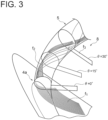
- the circumferential position in the scroll passage 5 from a tongue 4a of the scroll part 4 (see FIG. 2 ) to the outlet of the scroll passage 5 is represented by a central angle ⁇ about the rotational axis L by using the tongue 4a as a reference. Accordingly, the central angle ⁇ representing the circumferential position of the tongue 4a is 0°.
- the flow f 1 of compressed air discharged from the diffuser passage 8 in the vicinity of the tongue 4a swirls and flows through the scroll passage 5 along the inner wall surface of the scroll passage 5.
- this swirl flow f 2 of the compressed air circulates one round along the inner wall surface of the scroll passage 5 (in FIG. 3 , at a position where the central angle ⁇ is 30° approximately)
- the swirl flow f 2 interferes with compressed air f 3 discharged from the diffuser passage 8. This interference is one of factors of separation in the scroll passage 5.
- FIG. 5 shows an exemplary cross-sectional shape of the scroll passage 5 with a reduced inclination angle ⁇ .
- the second passage wall 7b includes a flat inner wall surface 21 which defines the diffuser passage 8 and is flat and perpendicular to the rotational axis L, a flat end surface 22 connected to the radially outermost portion of the flat inner wall surface 21 at right angle, a convex inner wall surface 23 connected to the end surface 22 and curved convexly with respect to the scroll passage 5, and a concave inner wall surface 24 connected to the convex inner wall surface 23 and curved concavely with respect to the scroll passage 5.
- the inner wall surface 5a of the scroll passage 5 is divided into a radially inner portion 5a2 and a radially outer portion 5a3 by a virtual line L' passing through the scroll center O s and parallel to the rotational axis L.
- the end surface 22, the convex inner wall surface 23, and the concave inner wall surface 24 are a part of the portion 5a2 of the inner wall surface 5a.
- Curving convexly with respect to the scroll passage 5 means that the curvature center of a convex arc portion 23a forming the convex inner wall surface 23 is positioned outside the scroll passage 5 in the cross-section of the housing 2 (see FIG. 2 ) including the rotational axis L, and curving concavely with respect to the scroll passage 5 means that the curvature center of a concave arc portion 24a forming the concave inner wall surface 24 is positioned inside the scroll passage 5 in the cross-section of the housing 2 (see FIG. 2 ) including the rotational axis L.
- the present inventors have found that separation is likely to occur in a range of the central angle ⁇ of 30° to 210° by CFD analysis.
- the reason is that when stable swirl flow is generated in the scroll passage 5, the swirl flow in the scroll passage 5 and the flow of the compressed air discharged from the diffuser passage 8 gradually stop interfering with each other, and thus interference is mainly caused on the upstream side in the scroll passage 5. Accordingly, by making the cross-sectional shape of the scroll passage 5 such that the inclination angle ⁇ is small on the upstream side, it is possible to effectively reduce the occurrence of separation.
- the cross-sectional shape of the scroll passage 5 shown in FIG. 5 is the shape of one cross-section of the housing 2 (see FIG. 2 ).
- the cross-sectional shape of the scroll passage 5 changes along the circumferential direction.
- the inclination angle ⁇ changes along the circumferential direction. That is, the inclination angle ⁇ is distributed along the circumferential direction of the scroll passage 5.
- FIG. 6 when the distribution of the inclination angle ⁇ has a minimum value in a range of the circumferential position of the scroll passage 5 where the central angle ⁇ is 30° to 210°, it is possible to effectively reduce the occurrence of separation.
- the distribution of the inclination angle ⁇ may not have the minimum value in the above range, but may have a local minimum value in the range of the central angle ⁇ of 30° to 210°. In other words, in a range of the central angle ⁇ larger than 210°, the distribution of the inclination angle ⁇ may have a value smaller than the local minimum value.
- the outer diameter of the diffuser passage 8 (see FIG. 1 ) is increased locally in the circumferential direction. More specifically, the distribution of the outer diameter of the diffuser passage 8 in the circumferential direction has a local maximum value or a maximum value in the range of the central angle ⁇ of 30° to 210°.
- the end surface 22 of the second passage wall 7b is located on a more radially outer side at a portion where the outer diameter of the diffuser passage 8 is locally increased than at other portions.
- the width of the concave inner wall surface 24 in the radial direction is increased, the inclination of the tangential direction A of the portion 5a1 becomes closer to the horizontal direction, and the inclination angle ⁇ is decreased.
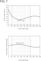
- FIG. 7 shows a graph representing the distribution of the outer diameter of the diffuser passage 8 in the circumferential direction and a graph representing the distribution of the inclination angle ⁇ in this case.
- the inclination angle ⁇ has a minimum value in the range of the central angle ⁇ of 30° to 210°.
- the outer diameter of the diffuser passage 8 has a local maximum value in the range of the central angle ⁇ of 30° to 210°.
- a distance R (see FIG. 2 ) from the rotational axis L to the scroll center O s of the scroll passage 5 is decreased locally in the circumferential direction. More specifically, the distribution of the distance R in the circumferential direction has a local minimum value or a minimum value in the range of the central angle ⁇ of 30° to 210°. Referring to FIG. 5 , the cross-section of the scroll passage 5 is located on a more radially inner side at a portion where the distance R is locally decreased than at other portions, although the outlet of the diffuser passage 8 is at the same position. Thus, since the inclination of the tangential direction A of the portion 5a1 becomes closer to the horizontal direction, the inclination angle ⁇ is decreased.
- FIG. 8 shows a graph representing the distribution of the distance R in the circumferential direction and a graph representing the distribution of inclination angle ⁇ in this case.
- the inclination angle ⁇ has a minimum value in the range of the central angle ⁇ of 30° to 210°.
- the distance R has a local minimum value in the range of the central angle ⁇ of 30° to 210°.
- locally increasing the outer diameter of the diffuser passage 8 (see FIG. 1 ) in the circumferential direction is combined with locally decreasing the distance R (see FIG. 2 ) from the rotational axis L to the scroll center O s of the scroll passage 5 in the circumferential direction. If one of these measures is adopted alone, the outer diameter of the diffuser passage 8 may be excessively locally increased, or the distance R may be excessively locally decreased. In this case, manufacturing may be difficult, or the flow f the compressed air may be adversely affected. However, by combining them, it is possible to moderate the local changes in the outer diameter of the diffuser passage 8 and the distance R.
- the second passage wall 7b includes the flat end surface 22 connected to the flat inner wall surface 21 at right angle, the convex inner wall surface 23 connected to the end surface 22 and curved convexly with respect to the scroll passage 5, and the concave inner wall surface 24 connected to the convex inner wall surface 23 and curved concavely with respect to the scroll passage 5.
- the end surface 22 may not be perpendicular to the flat inner wall surface 21.
- the end surface 22 may be not flat but curved.
- the convex inner wall surface 23 may be eliminated, and the concave inner wall surface 24 and the end surface may be connected to each other.
- FIG. 9 shows an example in which the concave inner wall surface 24 includes two concave inner wall surfaces.
- the two concave inner wall surfaces may form a first concave arc portion 241 and a second concave arc portion 242, respectively.
- the second concave arc portion 242 has a radially inner edge 242a and a radially outer edge 242b, and the edge 242a is connected to the first concave arc portion 241, and the edge 242b is connected to the convex arc portion 23a.
- the inclination angle ⁇ is an angle between the tangential direction A of the radially outer edge of the radially outermost concave arc portion, i.e. the tangential direction A of the radially outer edge 242b of the second concave arc portion 242, and the direction ⁇ perpendicular to the rotational axis L.
- the distribution of the inclination angle ⁇ has a local minimum value or a minimum value in the range of the central angle ⁇ of 30° to 210°, according to the invention it has a minimum value in the range of the central angle ⁇ of 30° to 120° (see FIG. 6 ).
- the flow passage area of the scroll passage 5 gradually decreases from the outlet toward the tongue 4a. Due to this shape of the scroll passage 5, the inclination angle ⁇ (see FIG. 5 ) of the concave arc portion 24a (see FIG. 5 ) tends to increase as it approximates to the tongue 4a.
- the scroll passage 5 is formed without considering the size of the inclination angle ⁇ , the inclination angle ⁇ tends to increase in the range of the central angle ⁇ of 30° to 120°.
- the inclination angle ⁇ is decreased in this range.
- interference between the swirl flow f 2 and the flow f 3 of the compressed fluid discharged from the diffuser passage 8 is reduced, and the occurrence of separation in the scroll passage 8 is reduced.
- the diffuser passage is generally formed by cutting, in the above embodiments, since the flat inner wall surface 21 defining the diffuser passage 8 is flat and perpendicular to the rotational axis L, it is easy to process the diffuser passage 8.
Landscapes
- Engineering & Computer Science (AREA)
- Mechanical Engineering (AREA)
- General Engineering & Computer Science (AREA)
- Chemical & Material Sciences (AREA)
- Combustion & Propulsion (AREA)
- Structures Of Non-Positive Displacement Pumps (AREA)
- Supercharger (AREA)
Claims (5)
- Zentrifugalkompressor (1), umfassend ein Impeller (3) und ein Gehäuse (2),wobei das Gehäuse (2) umfasst:ein Schneckenteil (4) mit einem Schneckendurchgang (5) in einer Spiralform, der an einer Außenumfangsseite des Impellers (3) ausgebildet ist; undein Diffusorteil (6), das ein Paar von Durchgangswänden (7) umfasst, die in einer Erstreckungsrichtung einer Drehachse (L) des Impellers (3) voneinander beabstandet sind, wobei das Diffusorteil (6) einen Diffusordurchgang (8) zwischen dem Paar von Durchgangswänden (7) bildet, wobei der Diffusordurchgang (8) mit dem Schneckendurchgang (5) entlang einer Umfangsrichtung des Schneckendurchgangs (5) an einer radial inneren Seite des Schneckenteils (4) in Verbindung steht,wobei das Paar von Durchgangswänden (7) umfasst:eine erste Durchgangswand (7a); undeine zweite Durchgangswand (7b), die näher an einer Schneckenmitte (Os) des Schneckendurchgangs (5) als die erste Durchgangswand (7a) an der Schneckenmitte (Os) in der Erstreckungsrichtung der Drehachse (L) positioniert ist,wobei die zweite Durchgangswand (7b) einen radial inneren Abschnitt (5a2) einer Innenwandfläche (5a) des Schneckendurchgangs (5) umfasst, und der radial innere Abschnitt (5a2) der Innenwandfläche (5a), der in der zweiten Durchgangswand (7b) enthalten ist, mindestens einen konkaven Bogenabschnitt (24a) mit einer Krümmungsmitte innerhalb des Schneckendurchgangs (5) in einem Querschnitt des Gehäuses (2) bildet, der durch eine Ebene gebildet wird, die die Drehachse (L) umfasst,wobei der mindestens eine konkave Bogenabschnitt (24a) einen radial äußersten konkaven Bogenabschnitt umfasst, der am äußersten in einer radialen Richtung des Impellers (3) angeordnet ist, und ein Neigungswinkel (α) zwischen einer tangentialen Richtung (A) einer radial äußeren Kante (24a1) des radial äußersten konkaven Bogenabschnitts und einer Richtung senkrecht zu der Drehachse (L) eine Verteilung entlang der Umfangsrichtung des Schneckendurchgangs (5) aufweist,dadurch gekennzeichnet, dass, wenn eine Umfangsposition in dem Schneckendurchgang (5) von einer Zunge (4a) des Schneckenteils (4) zu einem Auslass des Schneckendurchgangs (5) durch einen Mittelpunktswinkel (θ) um die Drehachse (L) unter Verwendung der Zunge (4a) als eine Referenz dargestellt wird, die Verteilung des Neigungswinkels (α) einen Minimalwert in einem Bereich des Mittelpunktswinkels (θ) von 30° bis 120° aufweist.
- Zentrifugalkompressor (1) nach Anspruch 1,
wobei die zweite Durchgangswand (7b) umfasst:eine flache Innenwandfläche (21), die den Diffusordurchgang (8) definiert und flach und senkrecht zu der Drehachse (L) ist;eine konvexe Innenwandfläche (23), die den Schneckendurchgang (5) definiert und in Bezug auf den Schneckendurchgang (5) konvex gekrümmt ist;mindestens eine konkave Innenwandfläche (24), die den Schneckendurchgang (5) definiert und den mindestens einen konkaven Bogenabschnitt (24a) in dem Querschnitt des Gehäuses (2) bildet, der durch die Ebene gebildet wird, die die Drehachse (L) umfasst, wobei die mindestens eine konkave Innenwandfläche (24) eine radial äußerste konkave Innenwandfläche umfasst, die am äußersten in der radialen Richtung des Impellers (3) angeordnet ist, wobei die radial äußerste konkave Innenwandfläche mit der konvexen Innenwandfläche (23) verbunden ist; undeine Endfläche (22), die die flache Innenfläche und die konvexe Innenwandfläche (23) an einem äußersten Abschnitt der flachen Innenfläche in der radialen Richtung des Impellers (3) verbindet. - Zentrifugalkompressor (1) nach einem der Ansprüche 1 oder 2,
wobei ein Außendurchmesser des Diffusordurchgangs (8) um die Drehachse (L) eine Verteilung in einer Umfangsrichtung des Diffusordurchgangs (8) aufweist und die Verteilung des Außendurchmessers des Diffusordurchgangs (8) einen lokalen Maximalwert oder einen Maximalwert in einem Bereich des Mittelpunktswinkels (θ) von 30° bis 210° aufweist. - Zentrifugalkompressor nach einem der Ansprüche 1 bis 3, wobei ein Abstand (R) von der Drehachse (L) zu der Schneckenmitte (Os) des Schneckendurchgangs (5) eine Verteilung in einer Umfangsrichtung des Diffusordurchgangs (8) aufweist und die Verteilung des Abstands (R) einen lokalen Minimalwert oder einen Minimalwert in einem Bereich des Mittelpunktswinkels (θ) von 30° bis 210° aufweist.
- Turbolader, umfassend den Zentrifugalkompressor (1) nach einem der Ansprüche 1 bis 4.
Applications Claiming Priority (1)
| Application Number | Priority Date | Filing Date | Title |
|---|---|---|---|
| PCT/JP2017/039909 WO2019087385A1 (ja) | 2017-11-06 | 2017-11-06 | 遠心圧縮機及びこの遠心圧縮機を備えたターボチャージャ |
Publications (3)
| Publication Number | Publication Date |
|---|---|
| EP3708848A1 EP3708848A1 (de) | 2020-09-16 |
| EP3708848A4 EP3708848A4 (de) | 2021-07-07 |
| EP3708848B1 true EP3708848B1 (de) | 2025-05-07 |
Family
ID=66331524
Family Applications (1)
| Application Number | Title | Priority Date | Filing Date |
|---|---|---|---|
| EP17930425.8A Active EP3708848B1 (de) | 2017-11-06 | 2017-11-06 | Radialverdichter und turbolader mit dem radialverdichter |
Country Status (5)
| Country | Link |
|---|---|
| US (1) | US11073164B2 (de) |
| EP (1) | EP3708848B1 (de) |
| JP (1) | JP6842564B2 (de) |
| CN (1) | CN110573748B (de) |
| WO (1) | WO2019087385A1 (de) |
Families Citing this family (7)
| Publication number | Priority date | Publication date | Assignee | Title |
|---|---|---|---|---|
| US11795969B2 (en) | 2019-05-30 | 2023-10-24 | Mitsubishi Heavy Industries Engine & Turbocharger, Ltd. | Centrifugal compressor and turbocharger |
| JP7413514B2 (ja) * | 2020-04-17 | 2024-01-15 | 三菱重工エンジン&ターボチャージャ株式会社 | スクロールケーシングおよび遠心圧縮機 |
| DE112020006913T5 (de) * | 2020-05-21 | 2023-01-19 | Mitsubishi Heavy Industries Engine & Turbocharger, Ltd. | Schneckengehäuse und zentrifugalverdichter |
| CN116057265B (zh) * | 2020-12-09 | 2025-07-25 | 株式会社Ihi | 离心压缩机及增压器 |
| CN114857088B (zh) * | 2022-05-30 | 2024-06-25 | 杭州老板电器股份有限公司 | 一种吸油烟机 |
| US20240355437A1 (en) * | 2023-04-21 | 2024-10-24 | Matrixcare, Inc. | Machine learning-based summarization and evaluation of clinical data |
| CN120281415A (zh) * | 2024-01-08 | 2025-07-08 | 宁波环球广电科技有限公司 | 参数调整方法及系统 |
Family Cites Families (10)
| Publication number | Priority date | Publication date | Assignee | Title |
|---|---|---|---|---|
| JP2005188337A (ja) * | 2003-12-25 | 2005-07-14 | Toyota Motor Corp | 作動流体還流路を有する過給用コンプレッサ |
| DE102007034236A1 (de) | 2007-07-23 | 2009-02-05 | Continental Automotive Gmbh | Radialverdichter mit einem Diffusor für den Einsatz bei einem Turbolader |
| JP5204016B2 (ja) * | 2009-03-17 | 2013-06-05 | 株式会社神戸製鋼所 | ターボ圧縮機 |
| JP5517914B2 (ja) * | 2010-12-27 | 2014-06-11 | 三菱重工業株式会社 | 遠心圧縮機のスクロール構造 |
| JP5479316B2 (ja) * | 2010-12-28 | 2014-04-23 | 三菱重工業株式会社 | 遠心圧縮機のスクロール構造 |
| JP5517981B2 (ja) | 2011-03-17 | 2014-06-11 | 三菱重工業株式会社 | 遠心圧縮機のスクロール構造 |
| JP5439423B2 (ja) * | 2011-03-25 | 2014-03-12 | 三菱重工業株式会社 | 遠心圧縮機のスクロール形状 |
| JP6062888B2 (ja) | 2014-07-07 | 2017-01-18 | トヨタ自動車株式会社 | 過給機 |
| DE112016005630T5 (de) * | 2015-12-10 | 2018-08-30 | Ihi Corporation | Ausstosspartie für einen radialverdichter |
| US10837297B2 (en) | 2015-12-25 | 2020-11-17 | Mitsubishi Heavy Industries Engine & Turbocharger, Ltd. | Centrifugal compressor and turbocharger |
-
2017
- 2017-11-06 US US16/605,454 patent/US11073164B2/en active Active
- 2017-11-06 WO PCT/JP2017/039909 patent/WO2019087385A1/ja not_active Ceased
- 2017-11-06 EP EP17930425.8A patent/EP3708848B1/de active Active
- 2017-11-06 JP JP2019550120A patent/JP6842564B2/ja active Active
- 2017-11-06 CN CN201780090061.3A patent/CN110573748B/zh active Active
Also Published As
| Publication number | Publication date |
|---|---|
| WO2019087385A1 (ja) | 2019-05-09 |
| JPWO2019087385A1 (ja) | 2020-04-23 |
| EP3708848A4 (de) | 2021-07-07 |
| US20210123456A1 (en) | 2021-04-29 |
| JP6842564B2 (ja) | 2021-03-17 |
| CN110573748A (zh) | 2019-12-13 |
| CN110573748B (zh) | 2021-06-01 |
| EP3708848A1 (de) | 2020-09-16 |
| US11073164B2 (en) | 2021-07-27 |
Similar Documents
| Publication | Publication Date | Title |
|---|---|---|
| EP3708848B1 (de) | Radialverdichter und turbolader mit dem radialverdichter | |
| JP7082948B2 (ja) | 遠心圧縮機、ターボチャージャ | |
| CN108700089B (zh) | 离心压缩机以及涡轮增压器 | |
| US10788045B2 (en) | Discharge section structure for centrifugal compressor | |
| US12460562B2 (en) | Mixed flow turbine and turbocharger | |
| CN107614885B (zh) | 涡壳以及离心压缩机 | |
| CN115380169B (zh) | 叶轮及离心压缩机 | |
| CN111911455A (zh) | 离心压缩机的叶轮、离心压缩机以及涡轮增压器 | |
| US11209015B2 (en) | Centrifugal compressor | |
| JP2021011828A (ja) | 多段遠心圧縮機 | |
| CN108700090A (zh) | 压缩机涡旋及离心压缩机 | |
| CN110582648B (zh) | 离心压缩机以及具有该离心压缩机的涡轮增压器 | |
| US11965524B2 (en) | Centrifugal compressor and turbocharger | |
| US11905969B2 (en) | Scroll structure of centrifugal compressor and centrifugal compressor | |
| US20250198310A1 (en) | Turbine | |
| JP7232332B2 (ja) | 遠心圧縮機のスクロール構造及び遠心圧縮機 | |
| JP6950831B2 (ja) | 遠心圧縮機 | |
| JP2025094607A (ja) | 軸流タービン | |
| JP2012057489A (ja) | 遠心圧縮機のディフューザおよびこれを備えた遠心圧縮機 | |
| JPWO2019193683A1 (ja) | 遠心圧縮機及びこの遠心圧縮機を備えたターボチャージャ |
Legal Events
| Date | Code | Title | Description |
|---|---|---|---|
| STAA | Information on the status of an ep patent application or granted ep patent |
Free format text: STATUS: THE INTERNATIONAL PUBLICATION HAS BEEN MADE |
|
| PUAI | Public reference made under article 153(3) epc to a published international application that has entered the european phase |
Free format text: ORIGINAL CODE: 0009012 |
|
| STAA | Information on the status of an ep patent application or granted ep patent |
Free format text: STATUS: REQUEST FOR EXAMINATION WAS MADE |
|
| 17P | Request for examination filed |
Effective date: 20191030 |
|
| AK | Designated contracting states |
Kind code of ref document: A1 Designated state(s): AL AT BE BG CH CY CZ DE DK EE ES FI FR GB GR HR HU IE IS IT LI LT LU LV MC MK MT NL NO PL PT RO RS SE SI SK SM TR |
|
| AX | Request for extension of the european patent |
Extension state: BA ME |
|
| DAV | Request for validation of the european patent (deleted) | ||
| DAX | Request for extension of the european patent (deleted) | ||
| A4 | Supplementary search report drawn up and despatched |
Effective date: 20210604 |
|
| RIC1 | Information provided on ipc code assigned before grant |
Ipc: F04D 29/44 20060101AFI20210528BHEP Ipc: F02B 39/00 20060101ALI20210528BHEP Ipc: F04D 29/42 20060101ALI20210528BHEP |
|
| STAA | Information on the status of an ep patent application or granted ep patent |
Free format text: STATUS: EXAMINATION IS IN PROGRESS |
|
| 17Q | First examination report despatched |
Effective date: 20230324 |
|
| GRAP | Despatch of communication of intention to grant a patent |
Free format text: ORIGINAL CODE: EPIDOSNIGR1 |
|
| STAA | Information on the status of an ep patent application or granted ep patent |
Free format text: STATUS: GRANT OF PATENT IS INTENDED |
|
| INTG | Intention to grant announced |
Effective date: 20241212 |
|
| GRAS | Grant fee paid |
Free format text: ORIGINAL CODE: EPIDOSNIGR3 |
|
| GRAA | (expected) grant |
Free format text: ORIGINAL CODE: 0009210 |
|
| STAA | Information on the status of an ep patent application or granted ep patent |
Free format text: STATUS: THE PATENT HAS BEEN GRANTED |
|
| AK | Designated contracting states |
Kind code of ref document: B1 Designated state(s): AL AT BE BG CH CY CZ DE DK EE ES FI FR GB GR HR HU IE IS IT LI LT LU LV MC MK MT NL NO PL PT RO RS SE SI SK SM TR |
|
| REG | Reference to a national code |
Ref country code: GB Ref legal event code: FG4D |
|
| REG | Reference to a national code |
Ref country code: CH Ref legal event code: EP |
|
| REG | Reference to a national code |
Ref country code: DE Ref legal event code: R096 Ref document number: 602017089399 Country of ref document: DE |
|
| REG | Reference to a national code |
Ref country code: IE Ref legal event code: FG4D |
|
| REG | Reference to a national code |
Ref country code: NL Ref legal event code: MP Effective date: 20250507 |
|
| PG25 | Lapsed in a contracting state [announced via postgrant information from national office to epo] |
Ref country code: ES Free format text: LAPSE BECAUSE OF FAILURE TO SUBMIT A TRANSLATION OF THE DESCRIPTION OR TO PAY THE FEE WITHIN THE PRESCRIBED TIME-LIMIT Effective date: 20250507 Ref country code: FI Free format text: LAPSE BECAUSE OF FAILURE TO SUBMIT A TRANSLATION OF THE DESCRIPTION OR TO PAY THE FEE WITHIN THE PRESCRIBED TIME-LIMIT Effective date: 20250507 Ref country code: PT Free format text: LAPSE BECAUSE OF FAILURE TO SUBMIT A TRANSLATION OF THE DESCRIPTION OR TO PAY THE FEE WITHIN THE PRESCRIBED TIME-LIMIT Effective date: 20250908 |
|
| REG | Reference to a national code |
Ref country code: LT Ref legal event code: MG9D |
|
| PG25 | Lapsed in a contracting state [announced via postgrant information from national office to epo] |
Ref country code: GR Free format text: LAPSE BECAUSE OF FAILURE TO SUBMIT A TRANSLATION OF THE DESCRIPTION OR TO PAY THE FEE WITHIN THE PRESCRIBED TIME-LIMIT Effective date: 20250808 Ref country code: NO Free format text: LAPSE BECAUSE OF FAILURE TO SUBMIT A TRANSLATION OF THE DESCRIPTION OR TO PAY THE FEE WITHIN THE PRESCRIBED TIME-LIMIT Effective date: 20250807 |
|
| PG25 | Lapsed in a contracting state [announced via postgrant information from national office to epo] |
Ref country code: PL Free format text: LAPSE BECAUSE OF FAILURE TO SUBMIT A TRANSLATION OF THE DESCRIPTION OR TO PAY THE FEE WITHIN THE PRESCRIBED TIME-LIMIT Effective date: 20250507 Ref country code: NL Free format text: LAPSE BECAUSE OF FAILURE TO SUBMIT A TRANSLATION OF THE DESCRIPTION OR TO PAY THE FEE WITHIN THE PRESCRIBED TIME-LIMIT Effective date: 20250507 |
|
| REG | Reference to a national code |
Ref country code: AT Ref legal event code: MK05 Ref document number: 1792735 Country of ref document: AT Kind code of ref document: T Effective date: 20250507 |
|
| PG25 | Lapsed in a contracting state [announced via postgrant information from national office to epo] |
Ref country code: BG Free format text: LAPSE BECAUSE OF FAILURE TO SUBMIT A TRANSLATION OF THE DESCRIPTION OR TO PAY THE FEE WITHIN THE PRESCRIBED TIME-LIMIT Effective date: 20250507 |
|
| PG25 | Lapsed in a contracting state [announced via postgrant information from national office to epo] |
Ref country code: HR Free format text: LAPSE BECAUSE OF FAILURE TO SUBMIT A TRANSLATION OF THE DESCRIPTION OR TO PAY THE FEE WITHIN THE PRESCRIBED TIME-LIMIT Effective date: 20250507 |
|
| PG25 | Lapsed in a contracting state [announced via postgrant information from national office to epo] |
Ref country code: AT Free format text: LAPSE BECAUSE OF FAILURE TO SUBMIT A TRANSLATION OF THE DESCRIPTION OR TO PAY THE FEE WITHIN THE PRESCRIBED TIME-LIMIT Effective date: 20250507 |
|
| PG25 | Lapsed in a contracting state [announced via postgrant information from national office to epo] |
Ref country code: RS Free format text: LAPSE BECAUSE OF FAILURE TO SUBMIT A TRANSLATION OF THE DESCRIPTION OR TO PAY THE FEE WITHIN THE PRESCRIBED TIME-LIMIT Effective date: 20250807 |
|
| PG25 | Lapsed in a contracting state [announced via postgrant information from national office to epo] |
Ref country code: IS Free format text: LAPSE BECAUSE OF FAILURE TO SUBMIT A TRANSLATION OF THE DESCRIPTION OR TO PAY THE FEE WITHIN THE PRESCRIBED TIME-LIMIT Effective date: 20250907 |
|
| PG25 | Lapsed in a contracting state [announced via postgrant information from national office to epo] |
Ref country code: LV Free format text: LAPSE BECAUSE OF FAILURE TO SUBMIT A TRANSLATION OF THE DESCRIPTION OR TO PAY THE FEE WITHIN THE PRESCRIBED TIME-LIMIT Effective date: 20250507 |
|
| PGFP | Annual fee paid to national office [announced via postgrant information from national office to epo] |
Ref country code: DE Payment date: 20250930 Year of fee payment: 9 |
|
| PG25 | Lapsed in a contracting state [announced via postgrant information from national office to epo] |
Ref country code: SM Free format text: LAPSE BECAUSE OF FAILURE TO SUBMIT A TRANSLATION OF THE DESCRIPTION OR TO PAY THE FEE WITHIN THE PRESCRIBED TIME-LIMIT Effective date: 20250507 Ref country code: DK Free format text: LAPSE BECAUSE OF FAILURE TO SUBMIT A TRANSLATION OF THE DESCRIPTION OR TO PAY THE FEE WITHIN THE PRESCRIBED TIME-LIMIT Effective date: 20250507 |
|
| PG25 | Lapsed in a contracting state [announced via postgrant information from national office to epo] |
Ref country code: CZ Free format text: LAPSE BECAUSE OF FAILURE TO SUBMIT A TRANSLATION OF THE DESCRIPTION OR TO PAY THE FEE WITHIN THE PRESCRIBED TIME-LIMIT Effective date: 20250507 |
|
| PG25 | Lapsed in a contracting state [announced via postgrant information from national office to epo] |
Ref country code: EE Free format text: LAPSE BECAUSE OF FAILURE TO SUBMIT A TRANSLATION OF THE DESCRIPTION OR TO PAY THE FEE WITHIN THE PRESCRIBED TIME-LIMIT Effective date: 20250507 |
|
| PG25 | Lapsed in a contracting state [announced via postgrant information from national office to epo] |
Ref country code: SK Free format text: LAPSE BECAUSE OF FAILURE TO SUBMIT A TRANSLATION OF THE DESCRIPTION OR TO PAY THE FEE WITHIN THE PRESCRIBED TIME-LIMIT Effective date: 20250507 Ref country code: RO Free format text: LAPSE BECAUSE OF FAILURE TO SUBMIT A TRANSLATION OF THE DESCRIPTION OR TO PAY THE FEE WITHIN THE PRESCRIBED TIME-LIMIT Effective date: 20250507 |
|
| PG25 | Lapsed in a contracting state [announced via postgrant information from national office to epo] |
Ref country code: IT Free format text: LAPSE BECAUSE OF FAILURE TO SUBMIT A TRANSLATION OF THE DESCRIPTION OR TO PAY THE FEE WITHIN THE PRESCRIBED TIME-LIMIT Effective date: 20250507 |
|
| REG | Reference to a national code |
Ref country code: DE Ref legal event code: R097 Ref document number: 602017089399 Country of ref document: DE |
|
| PLBE | No opposition filed within time limit |
Free format text: ORIGINAL CODE: 0009261 |
|
| STAA | Information on the status of an ep patent application or granted ep patent |
Free format text: STATUS: NO OPPOSITION FILED WITHIN TIME LIMIT |
|
| REG | Reference to a national code |
Ref country code: CH Ref legal event code: L10 Free format text: ST27 STATUS EVENT CODE: U-0-0-L10-L00 (AS PROVIDED BY THE NATIONAL OFFICE) Effective date: 20260318 |
|
| 26N | No opposition filed |
Effective date: 20260210 |