EP3708833B1 - Elektrische membranpumpe mit offset kulissenkurbel - Google Patents
Elektrische membranpumpe mit offset kulissenkurbel Download PDFInfo
- Publication number
- EP3708833B1 EP3708833B1 EP20161431.0A EP20161431A EP3708833B1 EP 3708833 B1 EP3708833 B1 EP 3708833B1 EP 20161431 A EP20161431 A EP 20161431A EP 3708833 B1 EP3708833 B1 EP 3708833B1
- Authority
- EP
- European Patent Office
- Prior art keywords
- piston
- diaphragm
- crankshaft
- axis
- cylinder
- Prior art date
- Legal status (The legal status is an assumption and is not a legal conclusion. Google has not performed a legal analysis and makes no representation as to the accuracy of the status listed.)
- Active
Links
Images


Classifications
-
- F—MECHANICAL ENGINEERING; LIGHTING; HEATING; WEAPONS; BLASTING
- F04—POSITIVE - DISPLACEMENT MACHINES FOR LIQUIDS; PUMPS FOR LIQUIDS OR ELASTIC FLUIDS
- F04B—POSITIVE-DISPLACEMENT MACHINES FOR LIQUIDS; PUMPS
- F04B39/00—Component parts, details, or accessories, of pumps or pumping systems specially adapted for elastic fluids, not otherwise provided for in, or of interest apart from, groups F04B25/00 - F04B37/00
- F04B39/0094—Component parts, details, or accessories, of pumps or pumping systems specially adapted for elastic fluids, not otherwise provided for in, or of interest apart from, groups F04B25/00 - F04B37/00 crankshaft
-
- F—MECHANICAL ENGINEERING; LIGHTING; HEATING; WEAPONS; BLASTING
- F04—POSITIVE - DISPLACEMENT MACHINES FOR LIQUIDS; PUMPS FOR LIQUIDS OR ELASTIC FLUIDS
- F04B—POSITIVE-DISPLACEMENT MACHINES FOR LIQUIDS; PUMPS
- F04B43/00—Machines, pumps, or pumping installations having flexible working members
- F04B43/02—Machines, pumps, or pumping installations having flexible working members having plate-like flexible members, e.g. diaphragms
- F04B43/04—Pumps having electric drive
-
- F—MECHANICAL ENGINEERING; LIGHTING; HEATING; WEAPONS; BLASTING
- F04—POSITIVE - DISPLACEMENT MACHINES FOR LIQUIDS; PUMPS FOR LIQUIDS OR ELASTIC FLUIDS
- F04C—ROTARY-PISTON, OR OSCILLATING-PISTON, POSITIVE-DISPLACEMENT MACHINES FOR LIQUIDS; ROTARY-PISTON, OR OSCILLATING-PISTON, POSITIVE-DISPLACEMENT PUMPS
- F04C2/00—Rotary-piston machines or pumps
- F04C2/02—Rotary-piston machines or pumps of arcuate-engagement type, i.e. with circular translatory movement of co-operating members, each member having the same number of teeth or tooth-equivalents
- F04C2/063—Rotary-piston machines or pumps of arcuate-engagement type, i.e. with circular translatory movement of co-operating members, each member having the same number of teeth or tooth-equivalents with coaxially-mounted members having continuously-changing circumferential spacing between them
- F04C2/07—Rotary-piston machines or pumps of arcuate-engagement type, i.e. with circular translatory movement of co-operating members, each member having the same number of teeth or tooth-equivalents with coaxially-mounted members having continuously-changing circumferential spacing between them having crankshaft-and-connecting-rod type drive
-
- F—MECHANICAL ENGINEERING; LIGHTING; HEATING; WEAPONS; BLASTING
- F04—POSITIVE - DISPLACEMENT MACHINES FOR LIQUIDS; PUMPS FOR LIQUIDS OR ELASTIC FLUIDS
- F04B—POSITIVE-DISPLACEMENT MACHINES FOR LIQUIDS; PUMPS
- F04B1/00—Multi-cylinder machines or pumps characterised by number or arrangement of cylinders
- F04B1/005—Pumps with cylinder axis arranged substantially tangentially to a circle centred on main shaft axis
-
- F—MECHANICAL ENGINEERING; LIGHTING; HEATING; WEAPONS; BLASTING
- F04—POSITIVE - DISPLACEMENT MACHINES FOR LIQUIDS; PUMPS FOR LIQUIDS OR ELASTIC FLUIDS
- F04B—POSITIVE-DISPLACEMENT MACHINES FOR LIQUIDS; PUMPS
- F04B1/00—Multi-cylinder machines or pumps characterised by number or arrangement of cylinders
- F04B1/04—Multi-cylinder machines or pumps characterised by number or arrangement of cylinders having cylinders in star- or fan-arrangement
- F04B1/0404—Details or component parts
- F04B1/0408—Pistons
-
- F—MECHANICAL ENGINEERING; LIGHTING; HEATING; WEAPONS; BLASTING
- F04—POSITIVE - DISPLACEMENT MACHINES FOR LIQUIDS; PUMPS FOR LIQUIDS OR ELASTIC FLUIDS
- F04B—POSITIVE-DISPLACEMENT MACHINES FOR LIQUIDS; PUMPS
- F04B15/00—Pumps adapted to handle specific fluids, e.g. by selection of specific materials for pumps or pump parts
- F04B15/02—Pumps adapted to handle specific fluids, e.g. by selection of specific materials for pumps or pump parts the fluids being viscous or non-homogeneous
-
- F—MECHANICAL ENGINEERING; LIGHTING; HEATING; WEAPONS; BLASTING
- F04—POSITIVE - DISPLACEMENT MACHINES FOR LIQUIDS; PUMPS FOR LIQUIDS OR ELASTIC FLUIDS
- F04B—POSITIVE-DISPLACEMENT MACHINES FOR LIQUIDS; PUMPS
- F04B17/00—Pumps characterised by combination with, or adaptation to, specific driving engines or motors
- F04B17/03—Pumps characterised by combination with, or adaptation to, specific driving engines or motors driven by electric motors
-
- F—MECHANICAL ENGINEERING; LIGHTING; HEATING; WEAPONS; BLASTING
- F04—POSITIVE - DISPLACEMENT MACHINES FOR LIQUIDS; PUMPS FOR LIQUIDS OR ELASTIC FLUIDS
- F04B—POSITIVE-DISPLACEMENT MACHINES FOR LIQUIDS; PUMPS
- F04B39/00—Component parts, details, or accessories, of pumps or pumping systems specially adapted for elastic fluids, not otherwise provided for in, or of interest apart from, groups F04B25/00 - F04B37/00
- F04B39/0005—Component parts, details, or accessories, of pumps or pumping systems specially adapted for elastic fluids, not otherwise provided for in, or of interest apart from, groups F04B25/00 - F04B37/00 adaptations of pistons
- F04B39/0022—Component parts, details, or accessories, of pumps or pumping systems specially adapted for elastic fluids, not otherwise provided for in, or of interest apart from, groups F04B25/00 - F04B37/00 adaptations of pistons piston rods
-
- F—MECHANICAL ENGINEERING; LIGHTING; HEATING; WEAPONS; BLASTING
- F04—POSITIVE - DISPLACEMENT MACHINES FOR LIQUIDS; PUMPS FOR LIQUIDS OR ELASTIC FLUIDS
- F04B—POSITIVE-DISPLACEMENT MACHINES FOR LIQUIDS; PUMPS
- F04B43/00—Machines, pumps, or pumping installations having flexible working members
- F04B43/02—Machines, pumps, or pumping installations having flexible working members having plate-like flexible members, e.g. diaphragms
- F04B43/025—Machines, pumps, or pumping installations having flexible working members having plate-like flexible members, e.g. diaphragms two or more plate-like pumping members in parallel
- F04B43/026—Machines, pumps, or pumping installations having flexible working members having plate-like flexible members, e.g. diaphragms two or more plate-like pumping members in parallel each plate-like pumping flexible member working in its own pumping chamber
-
- F—MECHANICAL ENGINEERING; LIGHTING; HEATING; WEAPONS; BLASTING
- F04—POSITIVE - DISPLACEMENT MACHINES FOR LIQUIDS; PUMPS FOR LIQUIDS OR ELASTIC FLUIDS
- F04B—POSITIVE-DISPLACEMENT MACHINES FOR LIQUIDS; PUMPS
- F04B43/00—Machines, pumps, or pumping installations having flexible working members
- F04B43/02—Machines, pumps, or pumping installations having flexible working members having plate-like flexible members, e.g. diaphragms
- F04B43/06—Pumps having fluid drive
- F04B43/067—Pumps having fluid drive the fluid being actuated directly by a piston
-
- F—MECHANICAL ENGINEERING; LIGHTING; HEATING; WEAPONS; BLASTING
- F04—POSITIVE - DISPLACEMENT MACHINES FOR LIQUIDS; PUMPS FOR LIQUIDS OR ELASTIC FLUIDS
- F04B—POSITIVE-DISPLACEMENT MACHINES FOR LIQUIDS; PUMPS
- F04B45/00—Pumps or pumping installations having flexible working members and specially adapted for elastic fluids
- F04B45/04—Pumps or pumping installations having flexible working members and specially adapted for elastic fluids having plate-like flexible members, e.g. diaphragms
- F04B45/047—Pumps having electric drive
-
- F—MECHANICAL ENGINEERING; LIGHTING; HEATING; WEAPONS; BLASTING
- F04—POSITIVE - DISPLACEMENT MACHINES FOR LIQUIDS; PUMPS FOR LIQUIDS OR ELASTIC FLUIDS
- F04B—POSITIVE-DISPLACEMENT MACHINES FOR LIQUIDS; PUMPS
- F04B53/00—Component parts, details or accessories not provided for in, or of interest apart from, groups F04B1/00 - F04B23/00 or F04B39/00 - F04B47/00
- F04B53/006—Crankshafts
-
- F—MECHANICAL ENGINEERING; LIGHTING; HEATING; WEAPONS; BLASTING
- F04—POSITIVE - DISPLACEMENT MACHINES FOR LIQUIDS; PUMPS FOR LIQUIDS OR ELASTIC FLUIDS
- F04B—POSITIVE-DISPLACEMENT MACHINES FOR LIQUIDS; PUMPS
- F04B53/00—Component parts, details or accessories not provided for in, or of interest apart from, groups F04B1/00 - F04B23/00 or F04B39/00 - F04B47/00
- F04B53/14—Pistons, piston-rods or piston-rod connections
-
- F—MECHANICAL ENGINEERING; LIGHTING; HEATING; WEAPONS; BLASTING
- F04—POSITIVE - DISPLACEMENT MACHINES FOR LIQUIDS; PUMPS FOR LIQUIDS OR ELASTIC FLUIDS
- F04B—POSITIVE-DISPLACEMENT MACHINES FOR LIQUIDS; PUMPS
- F04B53/00—Component parts, details or accessories not provided for in, or of interest apart from, groups F04B1/00 - F04B23/00 or F04B39/00 - F04B47/00
- F04B53/16—Casings; Cylinders; Cylinder liners or heads; Fluid connections
-
- F—MECHANICAL ENGINEERING; LIGHTING; HEATING; WEAPONS; BLASTING
- F04—POSITIVE - DISPLACEMENT MACHINES FOR LIQUIDS; PUMPS FOR LIQUIDS OR ELASTIC FLUIDS
- F04C—ROTARY-PISTON, OR OSCILLATING-PISTON, POSITIVE-DISPLACEMENT MACHINES FOR LIQUIDS; ROTARY-PISTON, OR OSCILLATING-PISTON, POSITIVE-DISPLACEMENT PUMPS
- F04C11/00—Combinations of two or more machines or pumps, each being of rotary-piston or oscillating-piston type; Pumping installations
- F04C11/005—Combinations of two or more machines or pumps, each being of rotary-piston or oscillating-piston type; Pumping installations of dissimilar working principle
- F04C11/006—Combinations of two or more machines or pumps, each being of rotary-piston or oscillating-piston type; Pumping installations of dissimilar working principle having complementary function
-
- F—MECHANICAL ENGINEERING; LIGHTING; HEATING; WEAPONS; BLASTING
- F04—POSITIVE - DISPLACEMENT MACHINES FOR LIQUIDS; PUMPS FOR LIQUIDS OR ELASTIC FLUIDS
- F04B—POSITIVE-DISPLACEMENT MACHINES FOR LIQUIDS; PUMPS
- F04B43/00—Machines, pumps, or pumping installations having flexible working members
- F04B43/02—Machines, pumps, or pumping installations having flexible working members having plate-like flexible members, e.g. diaphragms
Definitions
- the present disclosure relates to positive displacement pumps that are utilized to move liquids and slurries. More particularly, but not exclusively, the present disclosure relates to diaphragm pumps having an electric motor that is used to activate one or more diaphragms of the pump.
- Pumps can be used to facilitate the transfer of fluids, including, but not limited to, liquids, slurries, and mixtures.
- pumps such as, for example, positive displacement pumps, can be designed to handle a range of fluid viscosity, including fluids that include a relatively significant solid content, as well as be designed to pump relatively harsh chemicals.
- DE 10 2016 101 479 A1 refers to a known diaphragm compressor.
- US2012269664A1 relates to a motor pump unit with a dual diaphragm pump, wherein diaphragms and driving parts are made of one piece.
- DE4008459A1 is directed to a known double membrane pump.
- Positive displacement pumps can take a variety of different forms, including, for example, positive displacement pumps that utilize diaphragms or pistons in connection with the intake, and subsequent discharge, of a fluid from a chamber of the pump.
- positive displacement pumps that diaphragm pumps such pumps often include a pair of opposed diaphragms that reciprocate relative to one another along a common axis.
- these "double diaphragm" pumps have been pneumatically driven with high-pressure air.
- Such designs can allow pressures generated by the pump to be controlled by the pressure of the air in the system.
- a pneumatic drive can often prevent the generation of sparks, such air-operated diaphragm pumps are often suitable for operation in potentially explosive environments.
- AODP air operated diaphragm pumps
- the high-pressure air of the AODP is typically generated by an air compressor, which can be an additional piece of equipment, and associated cost, that is needed for the system.
- the reliance upon pneumatics can result in poor net operational energy usage due to the relatively significant losses of energy in the creation, transport, and conversion of high-pressure gas to mechanical work.
- the present invention relates to an apparatus comprising a diaphragm pump as defined in claim 1. Additionally, the present invention relates to a method according to claim 11. Additional features of the diaphragm pump apparatus or system and of the corresponding method are set out in the appended dependent claims and can provide further advantages.
- This Summary is provided to introduce a selection of concepts in a simplified form that are further described below in the Detailed Description. This Summary is not intended to identify key features or essential features of the claimed subject matter, nor is it intended to be used to limit the scope of the claimed subject matter. The scope of protection of the present invention is defined by the respective subject-matter of the appended claims.
- An aspect of an embodiment of the present disclosure is a diaphragm pump that can include a crankcase and a crankshaft, the crankshaft being at least partially positioned within the crankcase and rotatable about a rotational axis.
- the diaphragm pump can include a piston that is coupled to the crankshaft by a connecting rod, the piston being reciprocally displaceable within a piston cylinder and along an axis of motion between a suction stroke and a discharge stroke, the axis of motion intersecting a connection between the piston and the connecting rod.
- a diaphragm housing can be coupled to an end of the piston cylinder, and can be configured to at least partially define a pumping chamber and pump fluid through the pumping chamber as the piston reciprocates.
- a diaphragm pump system can include a crankcase, and a crankshaft that is at least partially positioned within the crankcase and coupled to the electric motor. Further, the crankshaft can be rotatable about a rotational axis. At least three pistons can be radially arranged around the crankcase, each piston of the at least three pistons being coupled to a throw of the crankshaft by a connecting rod. Additionally, each piston can be reciprocally displaceable within a piston cylinder and along an axis of motion between a suction stroke and a discharge stroke, the axis of motion for each piston of the at least three pistons intersects a connection between the piston and the connecting rod.
- the diaphragm pump system can also include at least three diaphragm housings that are each coupled to an end of a piston cylinder and configured to at least partially define a pumping chamber and pump fluid through the pumping chamber as the piston reciprocates. Further, the axis of motion of each of the at least three pistons may not intersect the rotational axis of the crankshaft such that a peak magnitude of piston side load forces encountered during the discharge stroke are reduced and a peak magnitude of piston side load forces encountered during the suction stroke is increased such that, relative to an arrangement in which the axes of motion do intersect the rotational axis, a closer balance is attained between the piston side load forces of the discharge stroke and the suction stroke.
- a diaphragm pump that can include a crankcase and a crankshaft, the crankshaft being at least partially positioned within the crankcase and rotatable about a rotational axis.
- the diaphragm pump can include a piston that is coupled to the crankshaft by a connecting rod, the piston being reciprocally displaceable within a piston cylinder between a suction stroke and a discharge stroke.
- a diaphragm housing can be coupled to an end of the piston cylinder, and can be configured to at least partially define a pumping chamber and pump fluid through the pumping chamber as the piston reciprocates.
- the piston cylinder can extend about a central longitudinal cylinder axis that intersects the rotational axis.
- the piston can be pivotally coupled to the connecting rod by a wrist pin that is positioned along a central longitudinal axis of the wrist pin that is parallel to, linearly offset from, the central longitudinal cylinder axis such that, relative to an arrangement in which the wrist pin is not linearly offset from the central longitudinal cylinder axis, a peak magnitude of piston side load forces encountered during the discharge stroke is reduced and a peak magnitude of piston side load forces encountered during the suction stroke is increased so as to attain a closer balance between the piston side load forces of the discharge stroke and the suction stroke.
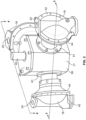
- FIG. 1 illustrates a diaphragm pump system 50 according to an illustrated embodiment of the present disclosure.
- the diaphragm pump system 50 can include, among other components, a diaphragm pump 10 that is operably coupled to a control system 12 and a driver 14. While embodiments discussed herein are discussed in terms of diaphragm pump systems, including electric diaphragm pump systems, at least certain features can also be applicable to a variety of other types of pump systems, including, but not limited to, other types of pumps and positive displacement pumps, including, but not limited to, positive displacement pumps that utilize pistons rather than diaphragms for displacement of fluids into/from a pumping chamber of the pump. Additionally, at least certain features of the diaphragm pump systems discussed herein can provide relatively significant advantages when compared to at least pneumatic diaphragm pump systems, including, but not limited to, increased energy efficiency in net operational energy usage.
- the control system 12 can include, for example, an external embedded controller 11 that is communicatively coupled to a human-machine interface 13, among other components.
- the external controller 11 can be configured to automate the operation of the diaphragm pump 10 for at least purposes of batching or dosing.
- the external controller 11 can also be configured to add other cycle counting functionality for the system 50.
- the external controller 11 can be configured to correlate speed of a driver 14, such as, for example, a motor speed, with a flow rate of a process fluid being pumped by the diaphragm pump.
- the external controller 11 can also include an override for extended periods of a stall event.
- the control system 12 may be optional to supplement a motor drive, such as a variable frequency drive (VFD) 15 that is configured to operate the driver 14.
- VFD variable frequency drive
- the diaphragm pump 10 can be mechanically coupled to the driver 14. While a variety of types of drivers 14 can be utilized, including, but not limited to, a variety of different types of engines and motors, according to the illustrated embodiment, the driver 14 is an electric motor. Additionally, the driver 14 can be operably coupled to a crankshaft 40 ( Figure 4 ) of the diaphragm pump system 50 such that operation of the driver 14 can facilitate rotational displacement of at least the crankshaft 40 about a crankshaft axis (or "rotational axis") 100 ( Figure 4 ).
- such operable coupling of the driver 14 to the crankshaft 40 can include a gearbox 16 that can be configured to adjust and/or control the relative speeds and torque transmitted from the driver 14 to the crankshaft 40.
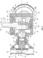
- the diaphragm pump 10 can include a crankcase 17, a plurality of diaphragm housings 18, a common inlet manifold 20 ( Figure 5 ), a common outlet manifold 38, and a slider crank mechanism 21 ( Figure 3 ), among other components.
- the crankcase 17 can include a lower crankcase 26 and an upper crankcase 28.
- the lower crankcase 26 can provide a lower crankcase cavity 86.
- the crankshaft 40 can protrude from the crankcase 17 for operable connection with the driver 14, as previously discussed.
- each diaphragm housing 18 can be coupled to an adjacent piston 68 of the slider crank mechanism 21, as shown, for example, in Figure 3 .
- the illustrated slider crank mechanism 21 can also include a cam 82 of the crankshaft 40, which can also referred to as a throw, and a connecting rod 62, as shown, for example, in Figure 4 .
- each of the diaphragm housings 18 can have generally similar components.
- at least certain components of the slider crank mechanism 21 that are associated with a particular diaphragm housing 18 can have the same configuration as other similar components of the slider crank mechanism 21 that are associated with another diaphragm housing 18.
- each of piston 68, piston cylinder 60, and/or connecting rod 62 of the slider crank mechanism 21 that is used with a particular diaphragm housing 18 can have similar configuration and features as a similar component that is used with another diaphragm housing 18.
- the diaphragm housing 18 can be configured to minimize or avoid contamination of process fluid that may leak past the diaphragm 80, such as, for example, leak past the diaphragm 80 as a result of the diaphragm 80 being damaged or worn. Such minimization or prevention of leakage past the diaphragm 80 can also minimize the disruption in the operation of, and/or damage to, the diaphragm 80, and thus the diaphragm pump 10. Additionally, the diaphragm pump 10 can similarly be designed to minimize or avoid contamination of the process fluid that may have leaked through the diaphragm 80.
- the containment cavity 81 can include low-pressure air, such as, for example, air that is around ambient pressure, including, for example, without about 0,68 bar (10 pounds per square inch (psi)) of ambient air pressure, as measured when the diaphragm pump 10 is not operating.
- This low-pressure air can be passed among the containment cavities 81 of the separate diaphragm housings 18. Because each diaphragm 80 is in a different phase of its stroke at any one time, significant pressure is not built up in the containment cavities 81.
- the piston 68 and piston cylinder 60 can be designed for controlled metal-to-metal sliding contact. Further, one or both of the piston 68 and the piston cylinder 60 can be surface treated, such as with a diamond coating, so as to control wear of one or both of the piston 68 and the piston cylinder 60. In other embodiments, a rolling contact can be provided between the piston 68 and the piston cylinder 60, such as, for example, via a rolling element bearing that is a recirculating ball track that is running against a rail.
- a sleeve or rider band 70 can be positioned circumferentially around a portion of the piston 6a that can minimize or prevent metal-to-metal contact between the piston 68 and an adjacent portion of the piston cylinder 60.
- the sleeve 70 which can be replaceable as a wear part, can be made from a variety of materials, including, for example, polymers, ceramics, or metals.
- Example polymers that may provide suitable wear properties across the necessary pressure and velocity ranges of the piston 68 can include Torlon ® , polyester reinforced resin, and bronze filled polytetrafluoroethylene (PTFE), among other materials.
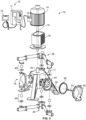
- Figure 6 illustrates a side view of a diaphragm pump 10 mounted to an alternative stand 30' in accordance with at least one embodiment of the subject disclosure.
- the stand 30' depicted in Figure 6 differs from the stand 30 of Figure 5 , and can comprise an upper stand portion 31, a lower stand portion 32, a stand base 34, and a plurality of supports 36.
- the diaphragm pump 10 can be attached to stand 30' at the upper portion stand portion 31, and/or at the lower stand portion 32.
- the stand base 34 can serve to secure the diaphragm pump 10 to a work surface or floor, among other surfaces. Additionally, the stand base 34 can be configured for relatively easily picked up, and moving, by a forklift or other trolley.
- Such a vertical orientation of the diaphragm pump 10 can provide numerous advantages, including, for example, a significantly reduced workplace footprint, and horizontal access to the pump 10 that may be relatively free of other pump equipment, which can be beneficial to the ability to perform maintenance on the pump 10, including, replacement, servicing and/or cleaning of the pump 10 and/or the components of the pump 10. Additionally, such a vertical orientation of the diaphragm pump 10 can permit one-way check valves 48 to operate based on gravity, which can potentially reduce the number of components of the check valves 48, including, for, example, avoiding springs to bias the balls within the check valves 48.
- the driver 14 depicted in Figures 1 , 5 , and 6 is shown as being mounted in a vertical orientation, the driver 14, as well as other components of the diaphragm pump system 50, can be mounted in a variety of other orientations.
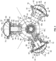
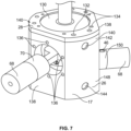
- Figure 7 illustrates a side perspective view of a crankcase 17 and pistons 68 of a diaphragm pump 10 according to an illustrated embodiment of the present disclosure. Moreover, Figure 7 depicts at least the lower crankcase 26 and the upper crankcase 28, with two of the pistons 68 protruding therefrom being viewable.
- the degree of the forces that act on the diaphragm pump 10 during the suction stroke versus those that act on the diaphragm pump 10 during the compression stroke can be very different.
- at least certain components of the diaphragm pump 10 utilized in the displacement of the diaphragms 80 can experience a relatively significant higher level ofload forces on the discharge stroke than the forces that those components encounter during the return/suction stroke. Accordingly, such components may experience higher wear rates on, and require increased mechanical integrity for, the discharge portion of the stroke.
- the slider crank mechanism 221 can have one or more pistons 68 that are displaced in a reciprocating manner within a corresponding piston cylinder 60 along an axis of motion 216 that is offset, and thus located out of plane, from the rotational axis 100 of the crankshaft 40.
- the axis of motion 216 intersects the corresponding connection at the wrist pin 64 of the piston 68 to the connecting rod 62.
- the axis of motion 216 extends through both the location at which the center of the wrist pin 64 is positioned when the piston 68 completes the discharge stroke, and the location at which the center of the wrist pin 64 is positioned when the piston 68 completes the suction stroke.
- the locations of the center of the wrist pin 64 when the piston 68 completes the discharge and suction strokes can be positioned on a central axis of the wrist pin 68 that is generally positioned along, or shared by, the axis of motion 216.
- the degree of offset between the axis of motion 216 and the rotational axis 100 of the crankshaft 40 can, according to certain embodiments, be a distance between at least the axis of motion 216 and the rotational axis 100 of the crankshaft 40.
- Offsetting of the axis of motion 216 relative to the rotational axis 100 of the crankshaft 40 can be achieved in a variety of different manners.
- the slider crank mechanism 221 depicted in Figures 11A and 11B is configured such that the axis of motion 216 along which the associated piston 68 is displaced in a reciprocating manner is linearly offset from the rotational axis 100 of the crankshaft 40.
- Such linear offsetting can be achieved, for example, by linearly adjusting the location of the axis of motion 216 such that the axis of motion 216 does not intersects, and is offset from, the rotational axis 100 of the crankshaft 40.
- the generally vertical orientation of the axis of motion 216 associated with a third piston 68 shown in Figure 11B is offset in a generally horizontal direction (as indicated by the direction "x" in Figure 11B ) such that rather than intersecting the rotational axis 100 of the crankshaft 40, the axis of motion 216 instead is offset to the right side of the rotational axis 100.
- Such linear offsetting of the axis of motion 216 of the slider crank mechanism 221 can be achieved in a variety of different manners.
- the cylinder bore 59 can be positioned or oriented such that the central longitudinal axis 218 of the cylinder bore 59 is linearly offset from the rotational axis 100 of the crankshaft 40.
- the central longitudinal axis 218 of the cylinder bore 59 and the corresponding axis of motion 216 can be offset by generally the same distance or magnitude, and in the same direction, from the rotational axis 100 of the crankshaft 40.
- the lower crankcase 26 can include one or more apertures 88 that are each sized and positioned to receive, or otherwise be coupled to, at least a portion of a piston cylinder 60.
- Such apertures 88 can be positioned and/or oriented such that the central longitudinal axis 217 of the aperture 88 is linearly offset from the rotational axis 100 of the crankshaft 40.
- such a central longitudinal axis 217 of the aperture 88 can be positioned such that, when the piston cylinders 60 are attached to the lower crankcase 26 and the slider crank mechanism 221 is assembled, the axis of motion 216 of the associated piston 68 is coplanar to the central longitudinal axis 217 of the aperture 88, and the central longitudinal axis 217 of the aperture 88 and the corresponding axis of motion 216 are therefore offset by generally the same distance or magnitude from the rotational axis 100 of the crank shaft 40.
- the magnitude of the offset between the axes of motion 216 and the rotational axis 100 of the crankshaft can be based on a variety of criteria, including, for example, but not limited to, stroke length.
- the axes of motion 216 may be offset from the rotational axis 100 of the crankshaft 40 by a distance of 0,254 cm (0.1 inches) to around 1,27 cm (0.5 inches), and more specifically, offset by about 0,399 cm (0.157 inches), among other distances.
- the offset features of the slider crank mechanism 221 can be configured to increase the duration of the discharge stroke during displacement of the piston 68 and associated operation of the diaphragm housings 118. As the degree of forces and stresses encountered on the discharge stroke can often be higher than those encountered on the suction stroke, increasing the amount of time spent on the discharge stroke can improve a balance between the piston side load forces and stresses that can be encountered during the discharge and suction strokes. As a result, the offset features of the slider crank mechanism 221 can reduce the maximum forces and stresses that are experienced by at least certain components of the slider crank mechanism 221 and/or the diaphragm housings 118.
- Such reduction of maximum forces and stresses can eliminate or reduce any need to overdesign at least the offset slider crank mechanism 221 and/or the diaphragm housings 118 of the pump 10, which can provide a cost savings. Further, such improved balancing of forces can facilitate a better balance of the expected wear on the diaphragms 80, as well as the wear between at least the interface between the piston cylinders 60 and the associated piston 68, sleeve or rider band 70, and/or an associated linear guide assembly ( Figures 15A and 15B ), and thereby extend the useable life span of such components.
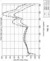
- Figure 12 provides a chart depicting examples of piston side load as a function of crank angle for slider crank mechanisms 221 of diaphragm pumps 10 having three levels of offset distance of the axes of motion 216 from the rotational axis 100.
- the illustrated piston side load force drops, at its lowest, to around 356 N (80 pounds-force (Ibf)), and reaches a maximum of around 2669 (600 lbf) during the discharge stroke.
- the maximum piston side load during the discharge stroke is about 7.5 times larger than the maximum piston-side load experienced during the suction stroke.
- an improved balance between the piston side load forces between the suction and discharge strokes is shown, as indicated by the piston side load force on the suction stroke reaching about -130 lbf, and the maximum piston side load force during the discharge stroke being about 450 lbf.
- the maximum piston side load forces during the discharge stroke drops to being about 3.5 times larger than the maximum piston side load forces on the suction stroke.
- such balancing of the piston side load force between the discharge and suction stroke can further be enhanced by increasing the offset distance to 1 cm (0.4 inches).
- the maximum piston side load forces for the suction and discharge strokes in this example are around 890 N (200 lbf) and around 1334 N (300 lbf), respectively.
- the maximum piston side load force for the discharge stroke drops to be about 1.5 times larger than the maximum piston side load force for the suction stroke. Accordingly, variations in the offset distance can reduce a peak magnitude of piston side load forces encountered during the discharge stroke while increasing a peak magnitude of piston side load forces encountered during the suction stroke. As a result, a closer balance can be attained between the piston side load forces that are encountered during the discharge and suction strokes.
- the diaphragm pump 10 can be designed and built using components that can withstand lower levels of forces. Moreover, with reference to the data shown in Figure 12 , rather than building a diaphragm pump 10 that can at least withstand maximum piston side load forces of around 2669 N (600 lbf), as shown as being experienced by the example slider crank mechanism 221 that had no offset feature, the diaphragm pump 10 can instead be built to at least withstand maximum piston side load forces of around 1334 N (300 lbf), as shown as being experienced by the example slider crank mechanism 221 having an offset of 1 cm (0.4 inches).
- Such a reduction of maximum forces and stresses via incorporation of offset features into the slider crank mechanism 221 can thus reduce, if not eliminate, any need to overdesign, such as, for example, oversize, components of at least the slider crank mechanism 221, which can provide cost and size advantages in terms of the components and manufacturing of the diaphragm pump.
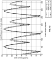
- the outlet pressure shown in Figure 13 can be the combined pressure effect of a diaphragm pump 10 having three diaphragm housings 118, and thus three corresponding pistons 68.
- the overall outlet pressure of the diaphragm pump 10 generally remains the same for each of the three levels of offset. Further, the extent that Figures 12 and 13 illustrate maximum piston side load forces and maximum I minimum pressures occurring at different crank angles, such differences can be attributed to at least changes in the durations of the suction and discharge strokes, as previously discussed.
- Figure 13 also demonstrates the use of an odd number of diaphragm housings 118 as increasing the number of pressure peaks that occur per each operating cycle.
- the number of pressure peaks can be equal to two times the number of diaphragm housings 118. Accordingly, as the data depicted in Figure 13 corresponds to an exemplary diaphragm pump 10 having three diaphragm housings 118, and the number of pressure peaks that occur per cycle is six, with three pressure peaks being generally around 7.92 bar (115 psi) and three other pressure peaks being generally around 7.03 bar (102 psi).
- the number of pressure peaks is typically equal to the number of diaphragm housings as each diaphragm has only one pressure peak.
- the additional pressure peaks provided by the use of an odd number of diaphragm housings 118 can be the product of the increased duration of the overlapping time periods in which multiple diaphragm housings 118 are undergoing discharge strokes.
- the duration at which multiple diaphragm housings 118 are simultaneously undergoing discharge strokes can also be increased.
- the increase in the number of pressure peaks per cycle can enhance loading sharing by the diaphragms 80 of the pump 10, as well as improve the average pressure that can be attained by the pump 10.
- the offset feature of the slider crank mechanism 221 can be provided in a variety of other manners.
- the wrist pin 64 can be linearly offset from the corresponding cylinder axis 116.
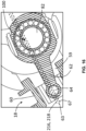
- Figure 14 illustrates a wrist pin 64 housed in a wrist pin cavity 65 in a piston 68 that is attached to a connecting rod 62 that is coupled to a cam 82.
- the cylinder axis 116 for a corresponding piston cylinder 60 (not shown), which also can serve as the axis of motion along which the piston 68 is reciprocally displaced, is positioned to intersect the rotational axis 100, with the rotational axis 100 not being positioned at the center of the cam 82.
- the central longitudinal axis 67 of the wrist pin 64 is positioned on the piston 68 at a location that is linearly offset from cylinder axis 116, as indicated by the distance "X" in Figure 14 .
- the pump 10 can include a slider crank mechanism 221 in which the axis of motion 216 for each diaphragm housing 18 is angularly offset relative to at least the rotational axis 100 of the crankshaft 40 such that the axis of motion 216 does not intersect the rotational axis 100.
- such offsetting of the axis of motion 216 can be achieved by angularly offsetting the central longitudinal axis 218 of the cylinder bore 59 of the piston cylinder 60 relative to at least the rotational axis 100 of the crankshaft 40.
- the cylinder bore S9 can be formed in the piston cylinder 60 such that the central longitudinal axis 218 of the cylinder bore S9 is angularly offset relative to a central longitudinal axis 63 of the piston cylinder 60.
- the central longitudinal axis 63 of the piston cylinder 60, and not the central longitudinal axis 218 of the cylinder bore S9 can be positioned and oriented to intersect the rotational axis 100.
- Figure 15A illustrates an enlarged view a portion of a pump 10 and an associated piston 68 of a slider crank mechanism 221 in which reciprocal displacement of the piston 68 is guided by a linear guide or bearing assembly 202.
- the linear guide assembly 202 can include a bearing block 204, a plurality of balls or rollers (not shown), and a rail 206.
- the plurality of balls or rollers which can function as bearings, can be positioned between the bearing block 204 and the rail 206 such that the balls or rollers are rotated as the bearing block 204 is linearly displaced along the rail 206, thereby assisting in the linear displacement of the bearing block 204 along the rail 206.
- bearing block 204 and rail 206 can having mating shapes so as facilitate the bearing block 204 being maintained in engagement with the rail 206, as well at least assist in maintaining the plurality of balls or rollers at an operable position between the bearing block 204 and the rail 206.
- Figure 15 also illustrates an embodiment in which the cylinder axis 216 for the corresponding piston cylinder 60, which also can serve as the axis of motion along which the piston 68 is reciprocally displaced, is positioned to intersect the rotational axis 100 of the crankshaft 40, with the rotational axis 100 not being positioned at the center of the cam 82.
- the central longitudinal axis 67 of the wrist pin 64 can be parallel to, but linearly offset from, the axis of motion 116, as indicated by the distance "X" in Figure 15A .
- Such an offset of the wrist pin 64 can also provide the connecting rod 62 with an adjusted angle of attack relative to the piston 68 that can at least increase the duration of the discharge stroke, which can also facilitate an improved balance of the piston side load forces experience during the suction and discharge strokes.
- linear guide assembly 202 is discussed above with respect to being used with a slider crank mechanism 221 having offset features similar to those shown in at least Figure 14 , the linear guide assembly 202 can also be used with other slider crank mechanisms that can have other types of offset features or configurations. Additionally, the linear guide assembly 202 can also be used with slider crank mechanisms that do not utilize offset features.
Landscapes
- Engineering & Computer Science (AREA)
- Mechanical Engineering (AREA)
- General Engineering & Computer Science (AREA)
- Reciprocating Pumps (AREA)
Claims (15)
- Eine Vorrichtung, die Folgendes beinhaltet:
eine Membranpumpe (10) die eine Vielzahl von Membranen (80) aufweist, die mindestens teilweise eine Vielzahl von Pumpkammern (46) definieren, wobei jede Membran (80) so strukturiert ist, dass sie sich zwischen einer ersten Position und einer zweiten Position hin- und herbewegt, um ein Fluid zu pumpen, wobei die Membranpumpe (10) Folgendes umfasst:ein Kurbelgehäuse (17) und eine Kurbelwelle (40), die mindestens teilweise in dem Kurbelgehäuse (17) angeordnet ist;dadurch gekennzeichnet, dass ein Ständer (30) so konfiguriert ist, dass er das Kurbelgehäuse (17) stützt, wobei der Ständer (30) so konfiguriert ist, dass er eine horizontale Stützfläche berührt;wobei die Kurbelwelle (40) eine Kurbelwellenachse aufweist, die in einer vertikalen Richtung durch den Ständer (30) ausgerichtet ist, wobei die Kurbelwelle betriebsmäßig mit einem Motor verbunden ist, sodass der Motor Leistung bereitstellt, um die Kurbelwelle (40) während des Betriebs zu drehen;wobei mindestens ein Nocken (82) so konfiguriert ist, dass er sich mit der Kurbelwelle (40) dreht, um die Hin- und Herbewegung der Vielzahl von Membranen (80) zu bewirken, wobei jede der Vielzahl von Membranen (80) so ausgerichtet ist, dass sie sich entlang einer Zylinderachse (116) orthogonal zu der Kurbelwellenachse hin und her bewegt;wobei die Membranpumpe (10) mindestens drei Membranen (80) und mindestens drei Pumpkammern (46) umfasst und wobei die mindestens drei Pumpkammern (46) gleichmäßig um die Kurbelwellenachse (100) verteilt sind, sodass die zwischen benachbarten Zylinderachsen (116) gebildeten Winkel im Wesentlichen gleich sind. - Vorrichtung gemäß Anspruch 1, wobei die Zylinderachsen (116) der Vielzahl von Membranen (80) relativ zueinander vertikal verschoben sind.
- Vorrichtung gemäß Anspruch 1 oder 2,
wobei jede der mindestens drei Membranen (80) durch einen einzigen Nocken (82) hin- und herbewegt wird. - Vorrichtung gemäß einem der vorhergehenden Ansprüche, wobei der Motor ein Elektromotor (14) mit einem drehbaren Rotor ist, wobei der drehbare Rotor in Leistungskommunikation mit der Kurbelwelle (40) steht und um eine Rotorachse parallel zu der Kurbelwellenachse drehbar ist;
wobei optional der Motor so konfiguriert ist, dass er angetrieben wird, um eine Drehzahl der Kurbelwelle (40) zu reduzieren und ein Drehmoment aufrechtzuerhalten, wenn ein Durchflussunterbrechungsereignis auftritt. - Vorrichtung gemäß einem der vorhergehenden Ansprüche, wobei der Ständer (30) eine Vielzahl von Füßen umfasst, die sich von dem Kurbelgehäuse (17) aus erstrecken.
- Vorrichtung gemäß einem der vorhergehenden Ansprüche, wobei jede der Zylinderachsen (116) gegenüber der Kurbelwellenachse (100) versetzt ist und wobei die Membranpumpe (10) ferner einen Zylinder (60) für jede der Vielzahl von Membranen (80) umfasst, wobei jeder Zylinder (60) entlang der Zylinderachse (116) eingerichtet ist und ein Kolben (68) innerhalb des Zylinders (60) angeordnet ist, wobei der Kolben (68) mit der Kurbelwelle (40) durch eine Verbindungsstange verbunden ist.
- Vorrichtung gemäß Anspruch 6, wobei jeder der Kolben (68) so strukturiert ist, dass er die jeweilige Membran (80) direkt zwischen der ersten Position und der zweiten Position bewegt;
wobei optional eine hin- und hergehende Verschiebung jedes der Kolben (68) entlang der Zylinderachse (116) durch ein Wälzelementlager zwischen dem Kolben (68) und dem Zylinder (60) geführt wird. - Vorrichtung gemäß Anspruch 7, wobei eine Dichtung zwischen dem Kolben (68) und dem Zylinder (60) angeordnet ist, um zu verhindern, dass ein Schmiermittel in einen Einschließungshohlraum (81) gelangt, wobei sich der Einschließungshohlraum (81) relativ zu der Membran (80) gegenüber der Pumpkammer (46) befindet;
wobei die Dichtung optional eine dem Schmiermittel zugewandte Dichtung und eine dem Einschließungshohlraum (81) zugewandte Dichtung umfasst, wobei die dem Einschließungshohlraum zugewandte Dichtung eine Faltenbalgdichtung ist. - Vorrichtung gemäß einem der Ansprüche 6-8, wobei die Membranen so ausgerichtet sind, dass eine bogenförmige Form eines ringförmigen flexiblen Abschnitts (83) jeder Membran (80) in einer Richtung im Allgemeinen weg von der Pumpkammer (46) angeordnet ist.
- Vorrichtung gemäß Anspruch 6, wobei jeder der Kolben ein Reiterband umfasst, das in Umfangsrichtung um mindestens einen Abschnitt des jeweiligen Kolbens positioniert ist.
- Ein Verfahren, das Folgendes beinhaltet:Einsetzen einer Kurbelwelle (40) mindestens teilweise in ein Kurbelgehäuse (17) einer Membranpumpe (10), wobei die Kurbelwelle (40) mindestens einen Nocken (82) und eine Kurbelwellenachse aufweist;dadurch gekennzeichnet, dass die Membranpumpe (10) mindestens drei Membranen (80) und mindestens drei Pumpkammern (46) beinhaltet;Koppeln eines Elektromotors (14) mit dem Kurbelgehäuse, wobei der Elektromotor (14) in Leistungskommunikation mit der Kurbelwelle (40) steht;Koppeln eines Ständers (30) mit dem Kurbelgehäuse (17), sodass die Kurbelwellenachse vertikal ausgerichtet ist, wenn das Kurbelgehäuse (17) von dem Ständer (30) gestützt wird;Ausrichten einer Zylinderachse (116) jedes der mindestens drei Membranpumpenzylinder (60) relativ zu der Kurbelwelle (40), wobei jede der jeweiligen Zylinderachsen (116) einen rechten Winkel zu der Kurbelwellenachse bildet, wenn sie von einer Seite quer sowohl zu der jeweiligen Zylinderachse (116) als auch zu der Kurbelwellenachse betrachtet wird; undBefestigen der mindestens drei Membranpumpenzylinder (60) an dem Kurbelgehäuse (17), wobei die Membranpumpenzylinder (60) in gleichen Winkeln um die Kurbelwellenachse (100) beabstandet sind.
- Verfahren gemäß Anspruch 11, das ferner das Ausrichten des Ständers (30) derart umfasst, dass die jeweiligen Zylinderachsen (116) der mindestens drei Membranpumpenzylinder horizontal sind.
- Verfahren gemäß Anspruch 11 oder 12, das ferner das Platzieren eines Kolbens (68) in jedem der jeweiligen Vielzahl von Membranpumpenzylindern (60) und das Verbinden einer Membran (68) in jedem jeweiligen Zylinder (60) mit dem jeweiligen Kolben (68) umfasst;
ferner optional umfassend das Befestigen einer Verbindungsstange (62) zwischen jedem Kolben (68) und dem Nocken (82). - Verfahren gemäß einem der Ansprüche 11-13, wobei das Ausrichten der Zylinderachse (116) das Versetzen der Zylinderachse (116) gegenüber der Kurbelwellenachse (100) umfasst.
- Verfahren gemäß einem der Ansprüche 11-14, das ferner Folgendes umfasst:Koppeln eines Wälzelementlagers zwischen jedem Kolben (68) und jedem Zylinder (60);Installieren einer dem Öl zugewandten Dichtung und einer dem Einschließungshohlraum (81) zugewandten Dichtung; und/oderBefestigen eines Reiterbandes (70) in Umfangsrichtung um mindestens einen Abschnitt eines jeden Kolbens (68).
Priority Applications (1)
| Application Number | Priority Date | Filing Date | Title |
|---|---|---|---|
| EP24186672.2A EP4417813A3 (de) | 2019-03-11 | 2020-03-06 | Elektrische membranpumpe mit offset kulissenkurbel |
Applications Claiming Priority (2)
| Application Number | Priority Date | Filing Date | Title |
|---|---|---|---|
| US201962816732P | 2019-03-11 | 2019-03-11 | |
| US16/723,425 US11434902B2 (en) | 2019-03-11 | 2019-12-20 | Electric diaphragm pump with offset slider crank |
Related Child Applications (1)
| Application Number | Title | Priority Date | Filing Date |
|---|---|---|---|
| EP24186672.2A Division EP4417813A3 (de) | 2019-03-11 | 2020-03-06 | Elektrische membranpumpe mit offset kulissenkurbel |
Publications (2)
| Publication Number | Publication Date |
|---|---|
| EP3708833A1 EP3708833A1 (de) | 2020-09-16 |
| EP3708833B1 true EP3708833B1 (de) | 2024-07-10 |
Family
ID=69779991
Family Applications (2)
| Application Number | Title | Priority Date | Filing Date |
|---|---|---|---|
| EP24186672.2A Pending EP4417813A3 (de) | 2019-03-11 | 2020-03-06 | Elektrische membranpumpe mit offset kulissenkurbel |
| EP20161431.0A Active EP3708833B1 (de) | 2019-03-11 | 2020-03-06 | Elektrische membranpumpe mit offset kulissenkurbel |
Family Applications Before (1)
| Application Number | Title | Priority Date | Filing Date |
|---|---|---|---|
| EP24186672.2A Pending EP4417813A3 (de) | 2019-03-11 | 2020-03-06 | Elektrische membranpumpe mit offset kulissenkurbel |
Country Status (3)
| Country | Link |
|---|---|
| US (3) | US11434902B2 (de) |
| EP (2) | EP4417813A3 (de) |
| CN (2) | CN111692083B (de) |
Families Citing this family (8)
| Publication number | Priority date | Publication date | Assignee | Title |
|---|---|---|---|---|
| EP4127475B1 (de) | 2020-03-31 | 2024-10-23 | Graco Minnesota Inc. | Elektrisch betriebene pumpe für ein mehr komponenten-sprüh-system |
| EP4127471A1 (de) | 2020-03-31 | 2023-02-08 | Graco Minnesota Inc. | Elektrisch betriebene verdrängerpumpe |
| CN112178143B (zh) * | 2020-09-22 | 2021-08-10 | 青岛理工大学(临沂)管理委员会办公室 | 一种可控制平衡惯性力的曲柄滑块机构 |
| CN112696341A (zh) * | 2020-12-21 | 2021-04-23 | 深圳安吉尔饮水产业集团有限公司 | 隔膜增压泵的泵头、隔膜增压泵、水处理装置 |
| GB202210470D0 (en) * | 2022-07-15 | 2022-08-31 | Seaweed Energy Ltd | Apparatus and method for wave energy conversion |
| CN117145944B (zh) * | 2023-10-18 | 2025-08-26 | 四川千里倍益康医疗科技股份有限公司 | 无级变幅传动机构及筋膜枪 |
| CN117006025B (zh) * | 2023-08-22 | 2024-01-26 | 无锡市东亚泵业有限公司 | 一种注聚泵 |
| US20250257728A1 (en) * | 2024-02-14 | 2025-08-14 | Ingersoll-Rand Industrial U.S., Inc. | Pump with conduit system fluidly coupled to cylinders |
Family Cites Families (32)
| Publication number | Priority date | Publication date | Assignee | Title |
|---|---|---|---|---|
| US781678A (en) * | 1904-05-17 | 1905-02-07 | Clarence H Richwood | Air-compressing machine. |
| DE837205C (de) * | 1948-10-02 | 1952-04-21 | Bochumer Eisen Heintzmann | Pumpe |
| US2997029A (en) * | 1958-06-20 | 1961-08-22 | Thomsen Supply Inc | Fluid powered actuator |
| GB933643A (en) * | 1959-01-30 | 1963-08-08 | Dowty Hydraulic Units Ltd | Improvements in control apparatus for power transmissions |
| US4381179A (en) * | 1980-10-31 | 1983-04-26 | Lear Siegler, Inc. | Pumps with floating wrist pins |
| EP0055467B1 (de) * | 1980-12-29 | 1984-12-05 | LEWA Herbert Ott GmbH + Co. | Membranpumpe mit druckentlastet eingespannter Membran |
| CN2051679U (zh) * | 1989-08-08 | 1990-01-24 | 淄博农药机械厂 | 多缸活塞式隔膜泵 |
| DE4008459A1 (de) | 1990-03-16 | 1991-09-19 | Bosch Gmbh Robert | Doppelmembranpumpe |
| US5380267A (en) * | 1993-06-18 | 1995-01-10 | Datascope Investment Corp. | Noise-attenuating pneumatic compressor and medical apparatus incorporating same |
| US5558381A (en) * | 1994-10-14 | 1996-09-24 | Hughes Aircraft Co. | Carrier opener system |
| US5893318A (en) * | 1996-04-03 | 1999-04-13 | Cheng; Chi | Ball bearing piston and liner |
| DE19640596A1 (de) * | 1996-10-01 | 1998-04-02 | Rexroth Mannesmann Gmbh | Radialkolbenpumpe |
| US5934646A (en) * | 1997-04-04 | 1999-08-10 | Nok Corporation | Gate valve and cylinder apparatus |
| US6832900B2 (en) * | 2003-01-08 | 2004-12-21 | Thomas Industries Inc. | Piston mounting and balancing system |
| US6865981B2 (en) * | 2003-03-11 | 2005-03-15 | Ingersoll-Rand Company | Method of producing a pump |
| US20040197201A1 (en) * | 2003-04-03 | 2004-10-07 | Nicolae Moisidis | 4-Stage diaphragm compressor |
| US7329105B2 (en) * | 2003-12-03 | 2008-02-12 | Haldex Brake Corporation | Multi-directional pump |
| DE102005029481B4 (de) * | 2005-06-24 | 2008-04-10 | Bran + Luebbe Gmbh | Pumpengetriebe |
| EP1816350B1 (de) * | 2006-02-06 | 2012-04-11 | Peroni Pompe S.p.A. | Hubkolbenmembranpumpe |
| US7736132B2 (en) * | 2006-04-03 | 2010-06-15 | Respironics Oxytec, Inc. | Compressors and methods for use |
| MX2010009494A (es) * | 2008-02-28 | 2010-11-12 | Douglas K Furr | Motor de explosion interna de alta eficiencia. |
| DE102009054941A1 (de) * | 2009-12-18 | 2011-06-22 | Continental Teves AG & Co. OHG, 60488 | Motor-Pumpenaggregat |
| ITRE20130083A1 (it) * | 2013-11-08 | 2015-05-09 | Imovilli Pompe S R L | Pompa volumetrica alternativa a membrana per liquidi |
| US20170067455A1 (en) * | 2014-02-26 | 2017-03-09 | Techni Waterjet Pty Ltd | Linear actuator |
| CN204239208U (zh) * | 2014-07-23 | 2015-04-01 | 浙江伊诺环保科技有限公司 | 新型膜驱动变频计量泵 |
| US10082207B2 (en) * | 2014-12-23 | 2018-09-25 | Dresser-Rand Company | Piston assembly |
| JP6720213B2 (ja) * | 2015-01-22 | 2020-07-08 | エスピーエックス フロウ テクノロジー ジャーマニー ゲゼルシャフト ミット ベシュレンクテル ハフツング | クランク機構を備えたプロセスポンプ |
| DE102016101479A1 (de) * | 2016-01-28 | 2017-08-03 | Pierburg Gmbh | Membranverdichter |
| US20170218943A1 (en) * | 2016-01-29 | 2017-08-03 | Ramparts, Llc | Controller for pump system |
| US20170298919A1 (en) * | 2016-04-18 | 2017-10-19 | Ingersoll-Rand Company | Direct drive linear motor for conventionally arranged double diaphragm pump |
| JP6425683B2 (ja) * | 2016-05-27 | 2018-11-21 | 紀州技研工業株式会社 | ダイアフラムポンプ |
| CN107100830A (zh) * | 2017-04-20 | 2017-08-29 | 佛山市三水区广顺自动化设备有限公司 | 一种电动三缸活塞式隔膜泵 |
-
2019
- 2019-12-20 US US16/723,425 patent/US11434902B2/en active Active
-
2020
- 2020-03-06 EP EP24186672.2A patent/EP4417813A3/de active Pending
- 2020-03-06 EP EP20161431.0A patent/EP3708833B1/de active Active
- 2020-03-10 CN CN202010161297.5A patent/CN111692083B/zh active Active
- 2020-03-10 CN CN202411265538.5A patent/CN119103083B/zh active Active
-
2022
- 2022-07-06 US US17/858,500 patent/US11835043B2/en active Active
-
2023
- 2023-10-25 US US18/493,919 patent/US20240068471A1/en active Pending
Also Published As
| Publication number | Publication date |
|---|---|
| US11835043B2 (en) | 2023-12-05 |
| EP4417813A2 (de) | 2024-08-21 |
| CN111692083A (zh) | 2020-09-22 |
| EP4417813A3 (de) | 2024-10-09 |
| US20220333596A1 (en) | 2022-10-20 |
| CN119103083B (zh) | 2025-11-28 |
| US20200291936A1 (en) | 2020-09-17 |
| CN119103083A (zh) | 2024-12-10 |
| US11434902B2 (en) | 2022-09-06 |
| EP3708833A1 (de) | 2020-09-16 |
| CN111692083B (zh) | 2024-09-27 |
| US20240068471A1 (en) | 2024-02-29 |
Similar Documents
| Publication | Publication Date | Title |
|---|---|---|
| EP3708833B1 (de) | Elektrische membranpumpe mit offset kulissenkurbel | |
| US6412454B1 (en) | Rotary power unit | |
| CN201568303U (zh) | 对称平衡式同步旋转压缩机械 | |
| US7635255B2 (en) | Long piston hydraulic machines | |
| CA2494996C (en) | Long-piston hydraulic machines | |
| WO2001012990A1 (en) | Diaphragm pump | |
| KR100781391B1 (ko) | 구동모터를 이용한 왕복펌프 | |
| CN216554247U (zh) | 一种回转活塞压缩机 | |
| US20060120882A1 (en) | Motor or pump assemblies | |
| US11326587B2 (en) | Fluid pump | |
| CN100348862C (zh) | 双作用径向柱塞泵 | |
| CN114992077B (zh) | 一种往复泵 | |
| US20030202892A1 (en) | Positive displacement pump | |
| US4117770A (en) | Axial-piston hydraulic machine | |
| EP0482774A2 (de) | Verdrängerpumpe mit Dreh-Hubkolben | |
| US6978712B2 (en) | Variable displacement piston type pump | |
| KR20090126599A (ko) | 정밀유량제어에 적용되는 로타리 피스톤 펌프를 사용하는구성요소와 연결방식. | |
| EP2679819A1 (de) | Variable radiale Reihenflüssigkeitsvorrichtungen | |
| WO2023117320A1 (en) | Fluid pump, pump assembly and method of pumping fluid | |
| RU2569398C2 (ru) | Объемная роторная машина | |
| CN105041595A (zh) | 一种旋转曲面变量四柱塞高压无油水泵 | |
| MXPA06009651A (es) | Maquinas hidraulicas de piston largo |
Legal Events
| Date | Code | Title | Description |
|---|---|---|---|
| PUAI | Public reference made under article 153(3) epc to a published international application that has entered the european phase |
Free format text: ORIGINAL CODE: 0009012 |
|
| STAA | Information on the status of an ep patent application or granted ep patent |
Free format text: STATUS: THE APPLICATION HAS BEEN PUBLISHED |
|
| AK | Designated contracting states |
Kind code of ref document: A1 Designated state(s): AL AT BE BG CH CY CZ DE DK EE ES FI FR GB GR HR HU IE IS IT LI LT LU LV MC MK MT NL NO PL PT RO RS SE SI SK SM TR |
|
| AX | Request for extension of the european patent |
Extension state: BA ME |
|
| STAA | Information on the status of an ep patent application or granted ep patent |
Free format text: STATUS: REQUEST FOR EXAMINATION WAS MADE |
|
| 17P | Request for examination filed |
Effective date: 20210315 |
|
| RBV | Designated contracting states (corrected) |
Designated state(s): AL AT BE BG CH CY CZ DE DK EE ES FI FR GB GR HR HU IE IS IT LI LT LU LV MC MK MT NL NO PL PT RO RS SE SI SK SM TR |
|
| STAA | Information on the status of an ep patent application or granted ep patent |
Free format text: STATUS: EXAMINATION IS IN PROGRESS |
|
| 17Q | First examination report despatched |
Effective date: 20221021 |
|
| GRAP | Despatch of communication of intention to grant a patent |
Free format text: ORIGINAL CODE: EPIDOSNIGR1 |
|
| STAA | Information on the status of an ep patent application or granted ep patent |
Free format text: STATUS: GRANT OF PATENT IS INTENDED |
|
| INTG | Intention to grant announced |
Effective date: 20240220 |
|
| GRAS | Grant fee paid |
Free format text: ORIGINAL CODE: EPIDOSNIGR3 |
|
| GRAA | (expected) grant |
Free format text: ORIGINAL CODE: 0009210 |
|
| STAA | Information on the status of an ep patent application or granted ep patent |
Free format text: STATUS: THE PATENT HAS BEEN GRANTED |
|
| AK | Designated contracting states |
Kind code of ref document: B1 Designated state(s): AL AT BE BG CH CY CZ DE DK EE ES FI FR GB GR HR HU IE IS IT LI LT LU LV MC MK MT NL NO PL PT RO RS SE SI SK SM TR |
|
| REG | Reference to a national code |
Ref country code: CH Ref legal event code: EP |
|
| REG | Reference to a national code |
Ref country code: DE Ref legal event code: R096 Ref document number: 602020033603 Country of ref document: DE |
|
| REG | Reference to a national code |
Ref country code: LT Ref legal event code: MG9D |
|
| REG | Reference to a national code |
Ref country code: NL Ref legal event code: MP Effective date: 20240710 |
|
| PG25 | Lapsed in a contracting state [announced via postgrant information from national office to epo] |
Ref country code: PT Free format text: LAPSE BECAUSE OF FAILURE TO SUBMIT A TRANSLATION OF THE DESCRIPTION OR TO PAY THE FEE WITHIN THE PRESCRIBED TIME-LIMIT Effective date: 20241111 |
|
| REG | Reference to a national code |
Ref country code: AT Ref legal event code: MK05 Ref document number: 1702238 Country of ref document: AT Kind code of ref document: T Effective date: 20240710 |
|
| PG25 | Lapsed in a contracting state [announced via postgrant information from national office to epo] |
Ref country code: NL Free format text: LAPSE BECAUSE OF FAILURE TO SUBMIT A TRANSLATION OF THE DESCRIPTION OR TO PAY THE FEE WITHIN THE PRESCRIBED TIME-LIMIT Effective date: 20240710 |
|
| PG25 | Lapsed in a contracting state [announced via postgrant information from national office to epo] |
Ref country code: PT Free format text: LAPSE BECAUSE OF FAILURE TO SUBMIT A TRANSLATION OF THE DESCRIPTION OR TO PAY THE FEE WITHIN THE PRESCRIBED TIME-LIMIT Effective date: 20241111 Ref country code: NL Free format text: LAPSE BECAUSE OF FAILURE TO SUBMIT A TRANSLATION OF THE DESCRIPTION OR TO PAY THE FEE WITHIN THE PRESCRIBED TIME-LIMIT Effective date: 20240710 |
|
| PG25 | Lapsed in a contracting state [announced via postgrant information from national office to epo] |
Ref country code: NO Free format text: LAPSE BECAUSE OF FAILURE TO SUBMIT A TRANSLATION OF THE DESCRIPTION OR TO PAY THE FEE WITHIN THE PRESCRIBED TIME-LIMIT Effective date: 20241010 |
|
| PG25 | Lapsed in a contracting state [announced via postgrant information from national office to epo] |
Ref country code: FI Free format text: LAPSE BECAUSE OF FAILURE TO SUBMIT A TRANSLATION OF THE DESCRIPTION OR TO PAY THE FEE WITHIN THE PRESCRIBED TIME-LIMIT Effective date: 20240710 Ref country code: GR Free format text: LAPSE BECAUSE OF FAILURE TO SUBMIT A TRANSLATION OF THE DESCRIPTION OR TO PAY THE FEE WITHIN THE PRESCRIBED TIME-LIMIT Effective date: 20241011 Ref country code: PL Free format text: LAPSE BECAUSE OF FAILURE TO SUBMIT A TRANSLATION OF THE DESCRIPTION OR TO PAY THE FEE WITHIN THE PRESCRIBED TIME-LIMIT Effective date: 20240710 |
|
| PG25 | Lapsed in a contracting state [announced via postgrant information from national office to epo] |
Ref country code: BG Free format text: LAPSE BECAUSE OF FAILURE TO SUBMIT A TRANSLATION OF THE DESCRIPTION OR TO PAY THE FEE WITHIN THE PRESCRIBED TIME-LIMIT Effective date: 20240710 |
|
| PG25 | Lapsed in a contracting state [announced via postgrant information from national office to epo] |
Ref country code: LV Free format text: LAPSE BECAUSE OF FAILURE TO SUBMIT A TRANSLATION OF THE DESCRIPTION OR TO PAY THE FEE WITHIN THE PRESCRIBED TIME-LIMIT Effective date: 20240710 |
|
| PG25 | Lapsed in a contracting state [announced via postgrant information from national office to epo] |
Ref country code: AT Free format text: LAPSE BECAUSE OF FAILURE TO SUBMIT A TRANSLATION OF THE DESCRIPTION OR TO PAY THE FEE WITHIN THE PRESCRIBED TIME-LIMIT Effective date: 20240710 Ref country code: IS Free format text: LAPSE BECAUSE OF FAILURE TO SUBMIT A TRANSLATION OF THE DESCRIPTION OR TO PAY THE FEE WITHIN THE PRESCRIBED TIME-LIMIT Effective date: 20241110 |
|
| PG25 | Lapsed in a contracting state [announced via postgrant information from national office to epo] |
Ref country code: HR Free format text: LAPSE BECAUSE OF FAILURE TO SUBMIT A TRANSLATION OF THE DESCRIPTION OR TO PAY THE FEE WITHIN THE PRESCRIBED TIME-LIMIT Effective date: 20240710 |
|
| PG25 | Lapsed in a contracting state [announced via postgrant information from national office to epo] |
Ref country code: ES Free format text: LAPSE BECAUSE OF FAILURE TO SUBMIT A TRANSLATION OF THE DESCRIPTION OR TO PAY THE FEE WITHIN THE PRESCRIBED TIME-LIMIT Effective date: 20240710 Ref country code: RS Free format text: LAPSE BECAUSE OF FAILURE TO SUBMIT A TRANSLATION OF THE DESCRIPTION OR TO PAY THE FEE WITHIN THE PRESCRIBED TIME-LIMIT Effective date: 20241010 |
|
| PG25 | Lapsed in a contracting state [announced via postgrant information from national office to epo] |
Ref country code: RS Free format text: LAPSE BECAUSE OF FAILURE TO SUBMIT A TRANSLATION OF THE DESCRIPTION OR TO PAY THE FEE WITHIN THE PRESCRIBED TIME-LIMIT Effective date: 20241010 Ref country code: PL Free format text: LAPSE BECAUSE OF FAILURE TO SUBMIT A TRANSLATION OF THE DESCRIPTION OR TO PAY THE FEE WITHIN THE PRESCRIBED TIME-LIMIT Effective date: 20240710 Ref country code: NO Free format text: LAPSE BECAUSE OF FAILURE TO SUBMIT A TRANSLATION OF THE DESCRIPTION OR TO PAY THE FEE WITHIN THE PRESCRIBED TIME-LIMIT Effective date: 20241010 Ref country code: LV Free format text: LAPSE BECAUSE OF FAILURE TO SUBMIT A TRANSLATION OF THE DESCRIPTION OR TO PAY THE FEE WITHIN THE PRESCRIBED TIME-LIMIT Effective date: 20240710 Ref country code: IS Free format text: LAPSE BECAUSE OF FAILURE TO SUBMIT A TRANSLATION OF THE DESCRIPTION OR TO PAY THE FEE WITHIN THE PRESCRIBED TIME-LIMIT Effective date: 20241110 Ref country code: HR Free format text: LAPSE BECAUSE OF FAILURE TO SUBMIT A TRANSLATION OF THE DESCRIPTION OR TO PAY THE FEE WITHIN THE PRESCRIBED TIME-LIMIT Effective date: 20240710 Ref country code: GR Free format text: LAPSE BECAUSE OF FAILURE TO SUBMIT A TRANSLATION OF THE DESCRIPTION OR TO PAY THE FEE WITHIN THE PRESCRIBED TIME-LIMIT Effective date: 20241011 Ref country code: FI Free format text: LAPSE BECAUSE OF FAILURE TO SUBMIT A TRANSLATION OF THE DESCRIPTION OR TO PAY THE FEE WITHIN THE PRESCRIBED TIME-LIMIT Effective date: 20240710 Ref country code: ES Free format text: LAPSE BECAUSE OF FAILURE TO SUBMIT A TRANSLATION OF THE DESCRIPTION OR TO PAY THE FEE WITHIN THE PRESCRIBED TIME-LIMIT Effective date: 20240710 Ref country code: BG Free format text: LAPSE BECAUSE OF FAILURE TO SUBMIT A TRANSLATION OF THE DESCRIPTION OR TO PAY THE FEE WITHIN THE PRESCRIBED TIME-LIMIT Effective date: 20240710 Ref country code: AT Free format text: LAPSE BECAUSE OF FAILURE TO SUBMIT A TRANSLATION OF THE DESCRIPTION OR TO PAY THE FEE WITHIN THE PRESCRIBED TIME-LIMIT Effective date: 20240710 |
|
| REG | Reference to a national code |
Ref country code: DE Ref legal event code: R097 Ref document number: 602020033603 Country of ref document: DE |
|
| PG25 | Lapsed in a contracting state [announced via postgrant information from national office to epo] |
Ref country code: RO Free format text: LAPSE BECAUSE OF FAILURE TO SUBMIT A TRANSLATION OF THE DESCRIPTION OR TO PAY THE FEE WITHIN THE PRESCRIBED TIME-LIMIT Effective date: 20240710 Ref country code: SM Free format text: LAPSE BECAUSE OF FAILURE TO SUBMIT A TRANSLATION OF THE DESCRIPTION OR TO PAY THE FEE WITHIN THE PRESCRIBED TIME-LIMIT Effective date: 20240710 Ref country code: DK Free format text: LAPSE BECAUSE OF FAILURE TO SUBMIT A TRANSLATION OF THE DESCRIPTION OR TO PAY THE FEE WITHIN THE PRESCRIBED TIME-LIMIT Effective date: 20240710 |
|
| PG25 | Lapsed in a contracting state [announced via postgrant information from national office to epo] |
Ref country code: EE Free format text: LAPSE BECAUSE OF FAILURE TO SUBMIT A TRANSLATION OF THE DESCRIPTION OR TO PAY THE FEE WITHIN THE PRESCRIBED TIME-LIMIT Effective date: 20240710 |
|
| PG25 | Lapsed in a contracting state [announced via postgrant information from national office to epo] |
Ref country code: CZ Free format text: LAPSE BECAUSE OF FAILURE TO SUBMIT A TRANSLATION OF THE DESCRIPTION OR TO PAY THE FEE WITHIN THE PRESCRIBED TIME-LIMIT Effective date: 20240710 |
|
| PGFP | Annual fee paid to national office [announced via postgrant information from national office to epo] |
Ref country code: FR Payment date: 20250328 Year of fee payment: 6 |
|
| PG25 | Lapsed in a contracting state [announced via postgrant information from national office to epo] |
Ref country code: SK Free format text: LAPSE BECAUSE OF FAILURE TO SUBMIT A TRANSLATION OF THE DESCRIPTION OR TO PAY THE FEE WITHIN THE PRESCRIBED TIME-LIMIT Effective date: 20240710 |
|
| PGFP | Annual fee paid to national office [announced via postgrant information from national office to epo] |
Ref country code: GB Payment date: 20250331 Year of fee payment: 6 |
|
| PLBE | No opposition filed within time limit |
Free format text: ORIGINAL CODE: 0009261 |
|
| STAA | Information on the status of an ep patent application or granted ep patent |
Free format text: STATUS: NO OPPOSITION FILED WITHIN TIME LIMIT |
|
| 26N | No opposition filed |
Effective date: 20250411 |
|
| PGFP | Annual fee paid to national office [announced via postgrant information from national office to epo] |
Ref country code: DE Payment date: 20250331 Year of fee payment: 6 |
|
| PGFP | Annual fee paid to national office [announced via postgrant information from national office to epo] |
Ref country code: IT Payment date: 20250328 Year of fee payment: 6 |
|
| PG25 | Lapsed in a contracting state [announced via postgrant information from national office to epo] |
Ref country code: SE Free format text: LAPSE BECAUSE OF FAILURE TO SUBMIT A TRANSLATION OF THE DESCRIPTION OR TO PAY THE FEE WITHIN THE PRESCRIBED TIME-LIMIT Effective date: 20240710 |
|
| PG25 | Lapsed in a contracting state [announced via postgrant information from national office to epo] |
Ref country code: MC Free format text: LAPSE BECAUSE OF FAILURE TO SUBMIT A TRANSLATION OF THE DESCRIPTION OR TO PAY THE FEE WITHIN THE PRESCRIBED TIME-LIMIT Effective date: 20240710 |
|
| REG | Reference to a national code |
Ref country code: CH Ref legal event code: H13 Free format text: ST27 STATUS EVENT CODE: U-0-0-H10-H13 (AS PROVIDED BY THE NATIONAL OFFICE) Effective date: 20251024 |
|
| PG25 | Lapsed in a contracting state [announced via postgrant information from national office to epo] |
Ref country code: LU Free format text: LAPSE BECAUSE OF NON-PAYMENT OF DUE FEES Effective date: 20250306 |