EP3707995B1 - Milchtank - Google Patents
Milchtank Download PDFInfo
- Publication number
- EP3707995B1 EP3707995B1 EP20162760.1A EP20162760A EP3707995B1 EP 3707995 B1 EP3707995 B1 EP 3707995B1 EP 20162760 A EP20162760 A EP 20162760A EP 3707995 B1 EP3707995 B1 EP 3707995B1
- Authority
- EP
- European Patent Office
- Prior art keywords
- milk
- guide pin
- recess
- tank
- stirring rod
- Prior art date
- Legal status (The legal status is an assumption and is not a legal conclusion. Google has not performed a legal analysis and makes no representation as to the accuracy of the status listed.)
- Active
Links
Images

Classifications
-
- A—HUMAN NECESSITIES
- A01—AGRICULTURE; FORESTRY; ANIMAL HUSBANDRY; HUNTING; TRAPPING; FISHING
- A01J—MANUFACTURE OF DAIRY PRODUCTS
- A01J9/00—Milk receptacles
- A01J9/04—Milk receptacles with cooling arrangements
Definitions
- the present invention relates to a milk tank, preferably a milk cooling tank with a stirring device.
- the FR2933080B1 discloses a guide for a stirrer in the form of a ball.
- a guide made of several rods in combination with this ball can be provided, or a guide through a cylindrical ring. It is also possible that the positions of both guide elements are swapped.
- a disadvantage of this design is the alignment of the stirrer rod, which is attached to the upper part of the tank, with the axis of the cylindrical ring, which is attached to the lower part of the tank, or the axis of the circular path, which is defined by the rods, which are attached to the lower part of the tank. Any offset creates contact forces between the ball and the ring or the rods, which leads to heating of the milk and a risk of the milk turning into butter, which impairs the quality of the milk.
- the BE 672 572 A discloses an immersion stirrer for a milk jug, by means of which chilled milk can be stirred.
- the stirring blade of the immersion stirrer is held by a sleeve which is open at the bottom and has struts to stabilize the stirring movement.
- the EN 32 42 346 A1 reveals a stirring device from the paper industry
- the object of the present invention is to create a milk tank which can be manufactured with larger manufacturing tolerances and thus cost-efficiently, time-efficiently and which guarantees a high milk quality during processing.
- the present invention solves this problem by providing a milk tank with the features of claim 1 and/or 9.
- a milk tank according to the invention has a hollow space as a reservoir for storing and/or cooling milk.
- the reservoir preferably serves both for storing and for cooling milk.
- the tank has a stirring device with a stirring rod, also called a stirring shaft, which is arranged in the cavity.
- the stirring device can also have a drive unit and a drive shaft.
- the stirring rod can be connected to the drive shaft at an upper end.
- the stirring rod also preferably has stirring blades in its lower third for homogenizing the milk, which protrude radially.
- two or three stirring blades can be provided on one or more levels.
- the stirring rod has a first guide means, preferably at the end.
- the bottom of the tank has a second guide means.
- the guide means interact with each other.
- a recess according to the understanding of the present invention preferably has a bowl-shaped design, wherein the outer surfaces of this design are provided as stop surfaces for the other guide means.
- the recess can also extend over the entire length of the stirring rod. For hygienic reasons, however, it is preferred if the recess has a base.
- the recess can have a preferred depth of less than 20 cm, preferably less than 10 cm.
- the other of the two aforementioned guide means is designed as a guide pin. This protrudes at least partially into the recess, so that the recess serves as a stop for the pin if the stirring rod moves radially to its axis of rotation.
- the guide pin has a head with a contact surface with the recess. This contact surface is the surface that is brought into contact with the recess when the stirring rod is deflected radially.
- the head of the guide pin is designed as a torus and/or a double cone.
- this is formed from two conical surfaces that run towards each other.
- the two conical surfaces have a common base area that forms the contact zone.
- An imaginary or real intersection area of the two surfaces is arranged on the circumference around the base area.
- the contact surface of the guide pin which strikes the recess in the event of a radial movement of the stirring rod, is assigned according to the invention to the torus or the contact area of the two surfaces.
- two conical, tapered surfaces can also be provided above and below the torus.
- recesses can be realized, e.g. a recess with a hexagonal cross-section.
- the recess can preferably be designed as a cylindrical recess.
- the guide pin is fixed to the bottom of the milk tank. This also means that the position of the recess is on the stirring rod. The opening of the recess is directed towards the guide pin, allowing for easy and uncomplicated flow due to gravity.
- the minimum distance between the guide pin and the recess when the guide pin is centrally positioned in the recess, i.e. the clearance, is preferably at least 0.1 mm, preferably between 0.2 and 1.8 mm.
- interruptions in the contact surface of the guide pin can also be provided. This can additionally support the flow of milk or cleaning medium.
- the guide pin can be fixed by mechanical connecting means, preferably by a single connecting means, particularly preferably by screwing.
- the invention relates to a milk tank with a cavity for storing and cooling milk, wherein the tank has a stirring device with a stirring rod which is arranged in the cavity.
- the mechanical joint is designed as a cardan joint or alternatively as a ball head joint.
- the stirring rod can be suspended in the tank via the mechanical joint at a first end in a low-stress manner, wherein the stirring rod is guided via the guide means at a second end.
- the milk tank can in particular and preferably be designed as a vertical milk tank, but the milk tank can also be designed horizontally within the scope of the present invention.
- the milk tank can preferably have a longitudinal axis A, wherein the stirring rod is arranged parallel to the longitudinal axis A.
- the stirring rod can have a length of more than 2 meters.
- the bottom surface of the milk tank on which the guide pin is arranged runs at an angle to the longitudinal axis of the milk tank.
- "angled” does not mean parallel to the longitudinal axis and also not perpendicular to the longitudinal axis of the milk tank.
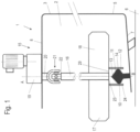
- FIG.1 A milk tank 1 of an arrangement for storing milk is shown schematically.
- This milk tank 1 is part of an arrangement for milk cooling and is designed in particular as a milk cooling tank.
- the arrangement also has a cooling circuit which operates according to the principle of a compression refrigeration machine and optionally an external control system for controlling and/or monitoring the operating states of the milk tank. Operating states are, for example, the empty state as "stand-by", emptying e.g. into a tank truck or filling, which typically takes place gradually.
- the milk tank 1 has a cavity 2 for receiving and cooling milk, which is delimited by a tank wall 3.
- the milk tank is preferably a vertical milk tank.
- the vertical milk tank 1 has a cylindrical surface 5, which defines a longitudinal axis A of the milk tank 1 and is part of the tank wall 3.
- other surfaces e.g. a surface of a prism with four, six, eight or more edges, are also possible.
- This longitudinal axis is essentially perpendicular to the base 6 on which the vertical milk tank 1 is set up and/or mounted.
- the milk tank 1 can have support feet (not shown in detail) and/or, in another embodiment, a support ring.
- the milk tank 1 has a bottom 7 at the end of the cylinder jacket surface 5 towards the base 6 and an end section 8 in the opposite direction for the end closure of the milk tank 1.
- the base 7 has a surface inclined to the longitudinal axis A of the milk tank in contact with a coolant.
- a guide pin 10 projects from the base surface 7 into the cavity 2.
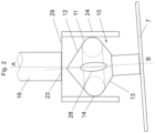
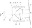
- This guide pin 10 is in Fig. 2 shown in detail. It has a longitudinal axis B and a bearing head 11 with two converging surfaces 12 and 13, the radius of which increases as the surfaces approach each other, and they taper off conically.
- the guide pin 10 has a radial contact surface 14, which is shaped as a torus. This is in Fig. 2 Alternatively, the two conical surfaces 12 and 13 that run towards each other can also form a double-conical shape of the head 11'. This is a variant of a guide pin 10' in Fig.4 in variation of Fig.2 shown. Tapered means that the radius of the surface is increasingly widening. Converging means, on the other hand, that the surfaces 12 and 13 approach each other in their axial course.
- the guide pin 10 serves to guide a stirring device 15.
- This stirring device 15 has a stirring rod 16 and stirring blades 17 and 18 projecting radially from the stirring rod.
- Fig.1 Only two stirring blades 17 and 18 are shown, but it is also possible that 3 or more stirring blades can be provided.
- the stirring rod 16 of the vertical milk tank 1 can be several meters long. Vibrations of the stirring rod are therefore possible during operation.
- the guide pin 10' makes it possible to compensate for these vibrations.
- a drive unit 19 which sets the stirring rod in rotation.
- This can in particular be a motor or a gear motor, which is preferably attached to the Outside of the milk tank 1 at the end section 8.
- the drive unit 19 is connected to the stirring rod 16 by a drive shaft 20.
- the offset between the axis A of the stirring rod 16 and the longitudinal axis B of the guide pin 10 generates wear forces between the contact zone of the guide pin 10 and the holder 24.
- a mechanical joint 21 is arranged between the drive shaft 20 and the stirring rod 16.
- the joint 21 can preferably be designed as a universal joint and/or as a ball joint or as an elastic, in particular torsionally elastic, coupling.
- Fig.1 shows the variant of a cardan joint, also called a universal joint. It has an intermediate piece 22 which can rotate about two axes, so that it is possible for the angle of deflection between the stirring rod 16 and the drive shaft 20 to change slightly during operation of the stirring device in order to reduce force influences, e.g. due to misalignment when assembling the stirring device 15, in particular the stirring rod 16.
- one of the two connection partners i.e. the drive shaft 20 or the stirring rod 16 has a ball head at a first end 22 and the other connection partner has a dome-shaped receptacle which can partially encompass the ball head.
- the guide pin 10 serves to guide the stirring rod 16 at its second end 23 opposite the drive shaft 20.
- the stirring rod 16 has a cylindrical recess 24 at the second end 23.
- the outer surface of the recess 24 is particularly cylindrical.
- the recess 24 is preferably open on at least one side towards the bottom 7 of the milk tank 1.
- the bottom of the recess 24, however, does not necessarily have to be flat but can be of variable design.
- the guide pin 10 serves to guide the cylindrical recess 24, into which the head 11 of the guide pin 10 projects at least partially and with play for movement within the recess 24.
- the recess 24 is open downwards, i.e. towards the base 7.
- the play i.e. the minimum distance between the recess 24 and the guide pin 10, can preferably be at least 0.1 mm, particularly preferably between 0.2 and 1.8 mm.
- the recess 24 does not sit directly on the guide pin 10, but the stirring rod 16 is suspended from the end section 8 of the milk tank 1, e.g. via the drive shaft 20 and the drive unit 19.
- the guide pin 10 can be conical at the end, in particular tapering towards the bottom 29 of the recess 24.
- the guide pin is connected, preferably detachably, to the bottom 7 of the milk tank 1 via mechanical connecting means, in particular screwed, particularly preferably screwed in a watertight manner.
- a double-conical shape of a bearing pin 10 is easier to manufacture than a spherical shape.
- the stirring device can compensate for movements of the stirring rod, which can occur in particular in the vertical variant of a milk tank due to the great length of the stirring rod.
- the guide pin 10 or recess 24 can have interruptions 28, e.g. grooves, arranged parallel or obliquely to the longitudinal axis B in order to enable a better drainage of milk or, in the case of cleaning, of water which gets into the space between the guide pin 10 and the recess 24.
- interruptions 28 e.g. grooves, arranged parallel or obliquely to the longitudinal axis B in order to enable a better drainage of milk or, in the case of cleaning, of water which gets into the space between the guide pin 10 and the recess 24.
- the Fig. 1-4 The variant of a milk tank according to the invention shown and described enables the homogenization of the milk and the temperature within a vertical tank.
- a vertical tank can, for example, be more than 7 meters high, with the appropriate dimensioning of the stirring device.
- the bearing of the stirring rod drive in the upper area of the tank enables a reduced weight load and friction on the guide means close to the ground, which in Fig. 1-4 the guide pin 10, 10', 10" and the recess 24 respectively.
Landscapes
- Life Sciences & Earth Sciences (AREA)
- Animal Husbandry (AREA)
- Environmental Sciences (AREA)
- Food-Manufacturing Devices (AREA)
- Accessories For Mixers (AREA)
Description
- Die vorliegende Erfindung betrifft einen Milchtank, vorzugsweise einen Milchkühltank mit einer Rührvorrichtung.
- Bei Milchtanks, insbesondere vertikalen Milchtank, werden meist lange Rührstäbe eingesetzt, um auch kleine Milchmengen im unteren Bereich des Milchtanks zu homogenisieren und die Gefahr eines Gefrierens von Milch relativ gering zu halten. Diese Rührer müssen bodennah geführt werden.
- Die
FR 2933080 B1 - Die
BE 672 572 A - Die
DE 32 42 346 A1 offenbart eine Rührvorrichtung aus der Papierindustrie - Ausgehend vom vorgenannten Stand der Technik ist es die Aufgabe der vorliegenden Erfindung einen Milchtank zu schaffen, welcher mit größeren Fertigungstoleranzen und dadurch kosteneffizient, zeiteffizient herstellbar ist und welcher eine hohe Milchqualität bei der Verarbeitung garantiert.
- Die vorliegende Erfindung löst diese Aufgabe durch das Bereitstellen eines Milchtanks mit den Merkmalen des Anspruchs 1 und/oder 9.
- Ein erfindungsgemäßer Milchtank weist einen Hohlraum als Reservoir zur Lagerung und/oder Kühlung von Milch auf. Bevorzugt dient das Reservoir dabei sowohl für die Lagerung als auch für die Kühlung von Milch.
- Der Tank weist eine Rührvorrichtung mit einem Rührstab, auch Rührwelle genannt, auf, welcher in dem Hohlraum angeordnet ist. Die Rührvorrichtung kann zudem eine Antriebseinheit und eine Antriebswelle aufweisen. Der Rührstab kann an einem oberen Ende mit der Antriebswelle verbunden sein. Der Rührstab weist zudem vorzugsweise in seinem unteren Drittel Rührblätter zur Homogenisierung der Milch auf, welche radial hervorstehen. Bevorzugt können zwei oder drei Rührblätter auf einer oder mehreren Ebenen vorgesehen sein.
- Der Rührstab weist, vorzugsweise endständig, ein erstes Führungsmittel auf. Der Boden des Tanks weist ein zweites Führungsmittel auf. Die Führungsmittel wechselwirken miteinander.
- Eines der beiden vorgenannten Führungsmittel ist als eine Ausnehmung ausgebildet. Eine Ausnehmung nach dem Verständnis der vorliegenden Erfindung weist vorzugsweise eine napfförmige Ausgestaltung auf, wobei die Mantelflächen dieser Ausgestaltung als Anschlagflächen für das andere Führungsmittel vorgesehen ist. Im Fall, dass der Rührstab als Hohlstab ausgebildet ist, kann sich die Ausnehmung auch über die gesamte Länge des Rührstabes erstrecken. Aus hygienischen Gründen ist es allerdings bevorzugt, wenn die Ausnehmung einen Boden aufweist. Die Ausnehmung kann dabei eine bevorzugte Tiefe von weniger als 20 cm, vorzugsweise weniger als 10 cm, aufweisen.
- Das andere der beiden vorgenannten Führungsmittel ist als ein Führungszapfen ausgebildet. Dieser ragt zumindest bereichsweise in die Ausnehmung hinein, so dass Ausnehmung als Anschlag für den Zapfen dient, sofern der Rührstab sich radial zu seiner Drehachse bewegt.
- Der Führungszapfen weist einen Kopf mit einer Kontaktfläche mit der Ausnehmung auf. Diese Kontaktfläche ist die Fläche, welche zum Anschlag mit der Ausnehmung bei radialer Auslenkung des Rührstabes gebracht wird.
- Der Kopf des Führungszapfens ist erfindungsgemäß als ein Torus und/oder ein Doppelkonus ausgebildet. Im Fall des Doppelkonus wird dieser aus zwei aufeinander zulaufende und zudem konisch-auslaufenden Flächen gebildet. Die beiden konisch-auslaufenden Flächen weisen eine gemeinsame Grundfläche auf, welche die Kontaktzone bildet. Umfangsseitig um die Grundfläche ist ein imaginärer oder realer Kreuzungsbereich der beiden Flächen angeordnet.
- Die Kontaktfläche des Führungszapfens, welche im Fall einer radialen Bewegung des Rührstabes an die Ausnehmung anschlägt, ist dabei erfindungsgemäß dem Torus oder dem Kontaktbereich der beiden Flächen zugeordnet.
- Im Fall des Torus können in einer vorteilhaften Ausführungsvariante oberhalb und unterhalb des Torus ebenfalls zwei aufeinander zulaufende, konisch-auslaufende Flächen vorgesehen sein.
- Weitere vorteilhafte Ausgestaltungen der Erfindung sind Gegenstand der Unteransprüche.
- Es sind im Rahmen der vorliegenden Erfindung verschiedene Varianten von Ausnehmungen realisierbar, z.B. eine Ausnehmung mit hexagonalem Querschnitt. Die Ausnehmung kann allerdings vorzugsweise als zylindrische Ausnehmung ausgebildet sein.
- Um ein Abfließen der Milch oder eines Reinigungsmediums aus der Ausnehmung zu erleichtern, ist es von Vorteil, wenn der Führungszapfen zu am Boden des Milchtanks festgelegt ist. Dies heißt zugleich, dass die Position der Ausnehmung am Rührstab ist. Durch die zum Führungszapfen hin gerichtete Öffnung der Ausnehmung kann ein Abfließen aufgrund der Schwerkraft einfach und unkompliziert erfolgen.
- Bevorzugt liegt ein Spiel zwischen dem Führungszapfen und der zylindrischen Ausnehmung vor. Der der Minimalabstand zwischen dem Führungszapfen und der Ausnehmung bei zentrischer Positionierung des Führungszapfens in der Ausnehmung, also das Spiel, beträgt bevorzugt zumindest 0,1 mm, vorzugsweise zwischen 0,2 bis 1,8 mm.
- Parallel oder schräg zur Längsachse B des Führungszapfens können zudem bevorzugt Unterbrechungen in der Kontaktfläche des Führungszapfens, vorzugsweise Rillen, vorgesehen sind. Dadurch kann ein Abfließen der Milch oder des Reinigungsmediums zusätzlich unterstützt werden.
- Der Führungszapfen kann ausgehend von der Kontaktfläche eine konische Fläche aufweisen, welche zum Boden der Ausnehmung hin spitz zuläuft.
- Der Führungszapfen kann über mechanische Verbindungsmittel, vorzugsweise über ein einziges Verbindungsmittel, besonders bevorzugt durch Verschraubung, festgelegt sein.
- Weiterhin erfindungsgemäß ist ein Milchtank mit einem Hohlraum zur Lagerung und Kühlung von Milch, wobei der Tank ein Rührvorrichtung mit einem Rührstab aufweist, welcher in dem Hohlraum angeordnet ist.
- Die Rührvorrichtung weist erfindungsgemäß eine Antriebseinheit mit einer Antriebswelle auf, welche über ein mechanisches Gelenk mit dem Rührstab verbunden ist. Das mechanische Gelenk ermöglicht eine lotrechte Auslenkung des Rührstabes, so dass eine geringfügige montagebedingte Fehlausrichtung des Rührstabes ausgeglichen werden kann und Fertigungstoleranzen erhöht werden können. Weiterhin sind die Kräfte zwischen der Kontaktzone und der Ausnehmung praktisch Null, was zu keiner Erwärmung der Milch oder zu einer Gefahr der Butterung führt und eine hohe Milchqualität garantiert.
- Dabei ist es von Vorteil, wenn das mechanische Gelenk als Kardan-Gelenk oder alternativ als Kugelkopf-Gelenk ausgebildet ist.
- Der Rührstab kann belastungsarm im Tank über das mechanische Gelenk hängend an einem ersten Ende aufgehängt sein, wobei der Rührstab über die Führungsmittel an einem zweiten Ende geführt ist.
- Der Milchtank kann insbesondere und bevorzugt als vertikaler Milchtank ausgebildet sein, allerdings kann der Milchtank im Rahmen der vorliegenden Erfindung auch horizontal ausgebildet sein. Bevorzugt kann der Milchtank eine Längsachse A aufweisen, wobei der Rührstab parallel zur Längsachse A angeordnet ist.
- Ebenfalls bevorzugt kann der Rührstab eine Länge von mehr als 2 Metern aufweist.
- Bevorzugt verläuft die Bodenfläche des Milchtanks, an welcher der Führungszapfen angeordnet ist, gegenüber der Längsachse des Milchtanks schräg. Schräg bedeutet bekanntermaßen nicht parallel zur Längsachse und auch nicht senkrecht zur Längsachse des Milchtanks.
- Weitere Vorteile, Merkmale und Einzelheiten der Erfindung ergeben sich aus der nachfolgenden Beschreibung, in der mehrere Ausführungsbeispiele der Erfindung anhand der beiliegenden Zeichnungen näher erläutert werden. Der Fachmann wird die in den Zeichnungen, der Beschreibung und den Ansprüchen in Kombination offenbarten Merkmale zweckmäßigerweise auch einzeln betrachten und zu sinnvollen weiteren Kombinationen zusammenfassen. Es zeigen:
- Fig. 1
- schematische Darstellung eines erfindungsgemäßen Milchtanks
- Fig. 2
- Detailansicht einer ersten Ausführungsvariante eines Führungszapfens in einem erfindungsgemäßen Milchtank
- Fig. 3
- Detailansicht des Führungszapfens in einer Draufsicht in einen erfindungsgemäßen Milchtank; und
- Fig. 4
- Detailansicht einer dritten Ausführungsvariante eines Führungszapfens in einem erfindungsgemäßen Milchtank.
- In
Fig. 1 ist schematisch ein Milchtank 1 einer Anordnung zum Lagern von Milch dargestellt. - Dieser Milchtank 1 ist Teil einer Anordnung zur Milchkühlung und ist insbesondere als Milchkühltank ausgebildet, weiterhin weist die Anordnung einen Kühlkreislauf auf, welcher nach dem Prinzip einer Kompressionskältemaschine arbeitet, und optional eine externe Steueranlage zur Steuerung und/oder Überwachung der Betriebszustände des Milchtanks. Als Betriebszustände sind z.B. der Leerzustand als "Stand-by", die Entleerung z.B. in einen Tankwagen oder die Befüllung, welche typischerweise allmählich erfolgt, zu verstehen. Der Milchtank 1 weist einen Hohlraum 2 zur Aufnahme und Kühlung von Milch auf, welcher durch eine Tankwand 3 begrenzt wird.
- Die Tankwand 3 weist eine Wandpartie oder mehrere Wandpartien auf, welche in Kontakt mit einem Kühlmittel stehen und welche sowohl im Bereich eines Bodens 7 als auch im unteren Bereich des Hohlraums 5 des Milchtanks zum Kühlen der Milch angeordnet sind und welche Teil zumindest eines Verdampfers oder mehrerer Verdampfer des vorgenannten Kühlkreislaufs ist oder sind. Der Kühlkreislauf kann zusätzlich zu dem Verdampfer oder den Verdampfern zumindest einen Kompressor, ein Regelorgan und einen Kondensator aufweisen.
- Wie aus
Fig. 1 erkennbar, handelt es sich bei dem Milchtank bevorzugt um einen vertikalen Milchtank. Der vertikale Milchtank 1 weist eine Zylindermantelfläche 5 auf, welche eine Längsachse A des Milchtanks 1 definiert und Teil der Tankwand 3 ist. Alternativ sind auch andere Mantelflächen, z.B. um eine Mantelfläche eines Prismas mit vier, sechs, acht oder mehr Kanten, handeln - Diese Längsachse steht im Wesentlichen senkrecht zum Untergrund 6, auf welchem der vertikale Milchtank 1 aufgestellt und/oder montiert ist. Dabei kann der Milchtank 1 über nicht-näher dargestellte Stützfüße verfügen und/oder in einer weiteren Ausführungsweise über einen Stützring verfügen.
- Der Milchtank 1 weist endständig an der Zylindermantelfläche 5 zum Untergrund 6 hin einen Boden 7 und in entgegengesetzter Richtung einen Endabschnitt 8 zum endseitigen Verschluss des Milchtanks 1 auf.
- Der Boden 7 weist eine zur Längsachse A des Milchtanks schräge Fläche in Kontakt mit einem Kühlmittel auf. Von der Bodenfläche 7 ragt ein Führungszapfen 10 in den Hohlraum 2 hinein. Dieser Führungszapfen 10 ist in
Fig. 2 im Detail dargestellt. Er weist eine Längsachse B und einen Lagerkopf 11 mit zwei aufeinander zulaufende Flächen 12 und 13 auf, deren Radius sich bei Annäherung der Flächen jeweils zunehmend erweitert, sie laufen konisch aus. - Im Übergangsbereich dieser beiden Flächen 12 und 13 weist der Führungszapfen 10 eine radiale Kontaktfläche 14 auf, welche als Torus ausgeformt ist. Dies ist in
Fig. 2 dargestellt. Alternativ können die beiden aufeinander zulaufende, konisch-auslaufende Flächen 12 und 13 auch eine doppelkonische Form des Kopfes 11' ausbilden. Dies ist einer Ausführungsvariante eines Führungszapfens 10' inFig. 4 in Abwandlung zuFig. 2 dargestellt. Konisch-auslaufend bedeutet dabei, dass sich der Radius der Fläche zunehmend erweitert. Aufeinander zulaufend bedeutet hingegen, dass sich die Flächen 12 und 13 in ihrem axialen Verlauf aneinander annähern. - Der Führungszapfen 10 dient der Führung einer Rührvorrichtung 15. Diese Rührvorrichtung 15 weist einen Rührstab 16 auf und radial vom Rührstab hervorstehende Rührblätter 17 und 18. In
Fig. 1 sind lediglich zwei Rührblätter 17 und 18 dargestellt, es ist allerdings auch möglich, dass 3 oder mehr Rührblätter vorgesehen sein können. - Der Rührstab 16 des vertikalen Milchtanks 1 kann mehrere Meter lang sein. Schwingungen des Rührstabs sind somit im Betrieb möglich. Der Führungszapfen 10 'ermöglicht es, diese Schwingungen auszugleichen.
- Weiterer Bestandteil der Rührvorrichtung 15 ist eine Antriebseinheit 19, welche den Rührstab in Rotation versetzt. Dabei kann es sich insbesondere um einen Motor oder einen Getriebemotor handeln, welcher vorzugsweise an der Außenseite des Milchtanks 1 am Endabschnitt 8 festgelegt ist. Die Verbindung der Antriebseinheit 19 mit dem Rührstab 16 erfolgt dabei durch eine Antriebswelle 20.
- Der Versatz zwischen der Achse A des Rührstabs 16 und der Längsachse B des Führungszapfens 10 erzeugt Verschleißkräfte zwischen der Kontaktzone dem Führungszapfen 10 und der Aufnahme 24. Um diese Kräfte zu beseitigen ist zwischen der Antriebswelle 20 und dem Rührstab 16 ein mechanisches Gelenk 21 angeordnet.
- Das Gelenk 21 kann bevorzugt als Kardangelenk und/oder als Kugelkopfgelenk oder als eine elastische, insbesondere drehelastische, Kupplung ausgebildet sein.
Fig. 1 zeigt die Variante eines Kardangelenks, auch Kreuzgelenk genannt. Es weist ein Zwischenstück 22 auf, welches um zwei Achsen rotierbar ist, so dass es möglich wird, dass sich der Beugungswinkel zwischen dem Rührstab 16 und der Antriebswelle 20 im Betrieb der Rührvorrichtung geringfügig verändern kann um Krafteinflüssen, z.B. durch Fehlausrichtung bei Montage der Rührvorrichtung 15, insbesondere des Rührstabs 16, zu mindern. - Im Fall eines Kugelkopfgelenks besitzt wahlweise einer der beiden Verbindungspartner, also die Antriebswelle 20 oder der Rührstab 16 an einem ersten Ende 22 einen Kugelkopf und der andere Verbindungspartner eine kalottenförmige Aufnahme, welche den Kugelkopf bereichsweise umgreifen kann.
- Der Führungszapfen 10 dient der endständigen Führung des Rührstabs 16 am seinem zur Antriebswelle 20 entgegengesetzten zweiten Ende 23. Hierfür weist der Rührstab 16 an dem zweiten Ende 23 eine zylindrische Ausnehmung 24 auf. Zylindrisch ist dabei insbesondere die Mantelfläche der Ausnehmung 24, Die Ausnehmung 24 ist bevorzugt zumindest einseitig zum Boden 7 des Milchtanks 1 hin offen ausgebildet. Der Boden der Ausnehmung 24 braucht hingegen nicht zwingend eben sondern kann variabel ausgebildet sein.
- Der Führungszapfen 10 dient der Führung der zylindrischen Ausnehmung 24, in welche der Kopf 11 des Führungszapfens 10 zumindest bereichsweise und mit Spiel zur Bewegung innerhalb der Ausnehmung 24 hineinragt. Hierfür ist die Ausnehmung 24 nach unten, also zum Boden 7 hin, offen. Das Spiel, also der Mindestabstand zwischen der Ausnehmung 24 und dem Führungszapfen 10, kann vorzugsweise zumindest 0,1 mm, besonders bevorzugt zwischen 0,2 bis 1,8 mm, betragen.
- Die Ausnehmung 24 sitzt dabei nicht unmittelbar auf dem Führungszapfen 10 auf, sondern der Rührstab 16 ist hängend an dem Endabschnitt 8 des Milchtanks 1, z.B. über die Antriebswelle 20 und die Antriebseinheit 19, festgelegt.
- Der Führungszapfen 10 kann endständig konisch, insbesondere zum Boden 29 der Ausnehmung 24 hin spitz zulaufend, ausgebildet sein. Der Führungszapfen ist dabei, vorzugsweise lösbar, über mechanische Verbindungsmittel mit dem Boden 7 des Milchtanks 1 verbunden, insbesondere verschraubt, besonders bevorzugt wasserdicht verschraubt.
- Der Gegenstand der Erfindung ist nicht auf das dargestellte Ausführungsbeispiel beschränkt. So ist es beispielsweise auch möglich im Rahmen der mechanischen Umkehr die Ausnehmung 24 am Boden 7 des Milchtanks1 und den Führungszapfen 10 endständig am Rührstab 16 anzuordnen.
- Dadurch wird, anders als beim Zusammenwirken zweier Zylinderflächen zwischen einem Führungszapfen und einer Ausnehmung, bei Verwendung einer torus- oder doppelkonischen Form des Lagerkopfes 11 ein Verkanten der Flächen bei Vibrationen, oder bei Fehlausrichtung des Rührstabs 16, z.B. durch geringfügig-versetzte Montage der Antriebseinheit 19 oder des Führungszapfens 10, verhindert.
- Zugleich ist insbesondere eine doppelkonische Form eines Lagerzapfens 10 im Vergleich zu einer Kugelform einfacher fertigbar. Im Zusammenspiel mit dem gelenkgelagerten Rührstab 16, welcher über das Gelenk 21 mit der Antriebswelle 20 verbunden ist, kann die Rührvorrichtung Bewegungen des Rührstabs ausgleichen, welcher insbesondere in der vertikalen Variante eines Milchtanks aufgrund der großen Länge des Rührstabes vorkommen kann.
- Der Führungszapfen 10 oder Ausnehmung 24 können parallel oder schräg zur Längsachse B angeordnete Unterbrechungen 28, z.B. Rillen, aufweisen, um einen besseren Abfluss von Milch, oder im Reinigungsfall von Wasser, welches in den Raum zwischen dem Führungszapfen 10 und der Ausnehmung 24 gelangt, zu ermöglichen.
- Die in
Fig. 1-4 dargestellte und beschriebene Variante eines erfindungsgemäßen Milchtanks ermöglicht die Homogenisierung der Milch und der Temperatur innerhalb eines vertikalen Tanks. Ein solcher Tank kann beispielsweise mehr als 7 Meter hoch sein, bei entsprechender Dimensionierung der Rührvorrichtung. Die Lagerung des Rührstabantriebs im oberen Bereich des Tanks ermöglicht dabei eine verminderte Gewichtsbelastung und Reibung auf die bodennahen Führungsmittel, welche inFig. 1-4 jeweils der Führungszapfen 10, 10', 10" und die Ausnehmung 24 sind. -
- 1
- Milchtank
- 2
- Hohlraum zur Aufnahme und Kühlung von Milch
- 3
- Tankwand
- 5
- Zylindermantelfläche
- 6
- Untergrund
- 7
- geneigter Boden des Milchtanks
- 8
- oberer Endabschnitt
- 10, 10',
- Führungszapfen
- 11, 11'
- Lagerkopf
- 12, 13
- konische Flächen
- 14
- radiale Kontaktfläche
- 15
- Rührvorrichtung
- 16
- Rührstab
- 17, 18
- Rührblätter
- 19
- Antriebseinheit
- 20
- Antriebswelle
- 21
- mechanisches Gelenk
- 22
- oberes Ende des Rührstabs
- 23
- unteres Ende des Rührstabs
- 24
- zylindrische Ausnehmung außenseitig vom Lagerkopf
- 28
- Unterbrechungen
- 29
- Boden der Ausnehmung außenseitig vom Lagerkopf
- 30
- Schraubkanal
- A
- Längsachse
- B
- Längsachse
Claims (17)
- Milchtank (1) mit einem Hohlraum (2) zur Lagerung und/oder Kühlung von Milch, wobei der Tank (1) eine Rührvorrichtung (15) mit einem Rührstab (16) aufweist, welcher in dem Hohlraum (2) angeordnet ist,wobei der Rührstab (16) ein erstes Führungsmittel aufweist und wobei der Boden (7) des Milchtanks (1) ein zweites Führungsmittel aufweist, welche miteinander wechselwirken,wobei zumindest eines der vorgenannten Führungsmittel eine Ausnehmung (24 ist und eines der vorgenannten Führungsmittel ein Führungszapfen (10, 10', 10") ist, welcher bereichsweise in die Ausnehmung (24) hineinragt,wobei der Führungszapfen (10, 10', 10") einen Lagerkopf (11, 11', 11") aufweist, mit einer Kontaktfläche (14) mit der Ausnehmung, (24) dadurch gekennzeichnet, dassder Lagerkopf (11, 11', 11") des Führungszapfens (10, 10', 10") einen Torus und/oder einen Doppelkonus mit zwei aufeinander zulaufende, konisch-auslaufende Flächen (12, 13) aufweist, und wobei die Kontaktfläche (14) dem Torus, oder dem Kreuzungsbereich der beiden Flächen (12, 13) zugeordnet ist.
- Milchtank nach Anspruch 1, dadurch gekennzeichnet, dass die Ausnehmung (24) als zylindrische Ausnehmung ausgebildet ist
- Milchtank nach Anspruch 1 oder 2, dadurch gekennzeichnet, dass der Führungszapfen (10, 10') mit dem Boden (7) des Milchtanks (1) lösbar und/oder fest verbunden ist.
- Milchtank nach einem der vorhergehenden Ansprüche, dadurch gekennzeichnet, dass ein Spiel zwischen dem Führungszapfen (10, 10') und der zylindrischen Ausnehmung (24) vorliegt
- Milchtank nach einem der vorhergehenden Ansprüche, dadurch gekennzeichnet, dass der Minimalabstand zwischen dem Führungszapfen (10, 10') und der Ausnehmung (24) bei zentrischer Positionierung des Führungszapfens (10, 10') in der Ausnehmung (24) zumindest 0,1 mm, vorzugsweise zwischen 0,2 bis 1,8 mm, beträgt.
- Milchtank nach einem der vorhergehenden Ansprüche, dadurch gekennzeichnet, dass parallel oder schräg zur Längsachse (B) des Führungszapfens (10') Unterbrechungen (28) der Kontaktfläche (14) des Führungszapfens (10'), vorzugsweise Rillen, vorgesehen sind, insbesondere zur Vermeidung von Ansammlungen und Butterung von Milch und zur Erleichterung der Reinigung.
- Milchtank nach einem der vorhergehenden Ansprüche, dadurch gekennzeichnet, dass der Führungszapfen (10, 10') ausgehend von der Kontaktfläche (14) eine konische Fläche (12) aufweist, welche zum Boden (29) der Ausnehmung (24) hin, insbesondere spitz, zuläuft um ein Ansammeln von Milch zu vermeiden.
- Milchtank nach einem der vorhergehenden Ansprüche, dadurch gekennzeichnet, dass der Führungszapfen (10, 10') über mechanische Verbindungsmittel, vorzugsweise über ein einziges Verbindungsmittel, besonders bevorzugt durch Verschraubung, festgelegt ist und vorzugsweise durch eine Dichtung geschützt ist um ein Ansammeln von Milch zu vermeiden.
- Milchkühltank (1) mit einem Hohlraum (2) zur Lagerung und Kühlung von Milch, wobei der Milchkühltank (1) eine Rührvorrichtung (15) mit einem Rührstab (16) aufweist, welcher in dem Hohlraum (2) angeordnet ist, wobei die Rührvorrichtung (15) eine Antriebseinheit (19) mit einer Antriebswelle (20) aufweist, welche über ein mechanisches Gelenk (21) mit dem Rührstab (16) verbunden ist.
- Milchkühltank nach Anspruch 9, dadurch gekennzeichnet, dass die Rührvorrichtung (15) eine Antriebseinheit (19) aufweist, welche den Rührstab (16) in Rotation versetzt und welche an der Außenseite des Milchtanks (1) festgelegt ist.
- Milchkühltank nach Anspruch 9 oder 10, dadurch gekennzeichnet, dass das mechanische Gelenk (21) als Kardan-Gelenk oder als Kugelkopf-Gelenk ausgebildet ist.
- Milchkühltank nach Anspruch 9 oder 10, dadurch gekennzeichnet, dass das mechanische Gelenk (21) als elastische Kupplung ausgebildet ist.
- Milchkühltank nach einem der vorhergehenden Ansprüche, dadurch gekennzeichnet, dass der Rührstab (16) im Milchtank (1) über das mechanische Gelenk (21) hängend an einem ersten Ende (22) aufgehängt ist, wobei der Rührstab (16) über die Führungsmittel an einem zweiten Ende (23) geführt ist.
- Milchkühltank nach einem der vorhergehenden Ansprüche, dadurch gekennzeichnet, dass der Milchtank (1) als vertikaler Milchtank ausgebildet ist.
- Milchtank nach einem der vorhergehenden Ansprüche, dadurch gekennzeichnet, dass der Milchkühltank (1) eine Längsachse (A) aufweist, wobei der Rührstab (16) parallel zur Längsachse (A) angeordnet ist.
- Milchkühltank nach einem der vorhergehenden Ansprüche, dadurch gekennzeichnet, dass der Rührstab (16) eine Länge von mehr als 2 Metern aufweist.
- Milchkühltank nach einem der vorhergehenden Ansprüche, dadurch gekennzeichnet, dass die Bodenfläche (7) des Milchtanks (1), an welcher der Führungszapfen (10, 10') angeordnet ist, gegenüber der Längsachse (A) des Milchtanks (1) schräg verläuft.
Applications Claiming Priority (1)
| Application Number | Priority Date | Filing Date | Title |
|---|---|---|---|
| DE202019101469.5U DE202019101469U1 (de) | 2019-03-14 | 2019-03-14 | Milchtank |
Publications (2)
| Publication Number | Publication Date |
|---|---|
| EP3707995A1 EP3707995A1 (de) | 2020-09-16 |
| EP3707995B1 true EP3707995B1 (de) | 2024-09-04 |
Family
ID=69810681
Family Applications (1)
| Application Number | Title | Priority Date | Filing Date |
|---|---|---|---|
| EP20162760.1A Active EP3707995B1 (de) | 2019-03-14 | 2020-03-12 | Milchtank |
Country Status (2)
| Country | Link |
|---|---|
| EP (1) | EP3707995B1 (de) |
| DE (1) | DE202019101469U1 (de) |
Citations (1)
| Publication number | Priority date | Publication date | Assignee | Title |
|---|---|---|---|---|
| EP3572778A1 (de) * | 2018-05-25 | 2019-11-27 | Robert Bosch GmbH | Flüssigkeitsbehälter, insbesondere milchtank mit rührwerksüberwachung |
Family Cites Families (3)
| Publication number | Priority date | Publication date | Assignee | Title |
|---|---|---|---|---|
| FR1459081A (fr) * | 1965-01-09 | 1966-04-29 | Wwk Kuehlung | Réfrigérateur à immersion pour réfrigération du lait |
| CH658875A5 (de) * | 1982-11-01 | 1986-12-15 | Escher Wyss Gmbh | Ruehrvorrichtung fuer papierstoff. |
| FR2933080B1 (fr) * | 2008-06-30 | 2010-06-25 | Serap Industries | Enceinte de stockage a zones ponctuelles de contact entre l'extremite de son arbre agitateur et des moyens de guidage |
-
2019
- 2019-03-14 DE DE202019101469.5U patent/DE202019101469U1/de not_active Expired - Lifetime
-
2020
- 2020-03-12 EP EP20162760.1A patent/EP3707995B1/de active Active
Patent Citations (1)
| Publication number | Priority date | Publication date | Assignee | Title |
|---|---|---|---|---|
| EP3572778A1 (de) * | 2018-05-25 | 2019-11-27 | Robert Bosch GmbH | Flüssigkeitsbehälter, insbesondere milchtank mit rührwerksüberwachung |
Also Published As
| Publication number | Publication date |
|---|---|
| EP3707995A1 (de) | 2020-09-16 |
| DE202019101469U1 (de) | 2020-06-18 |
Similar Documents
| Publication | Publication Date | Title |
|---|---|---|
| DE4232934A1 (de) | Doppel-Impeller zum Rühren von sterilen Flüssigkeiten | |
| EP2358467A1 (de) | Mischer mit drehbarem mischbehälter | |
| WO2017045846A2 (de) | Rührorgan, rührstabanordnung sowie transport- und lagerbehälter für flüssigkeiten mit einer rührstabanordnung | |
| WO2012072166A1 (de) | Getriebedeckel und getriebe | |
| DE102013214733A1 (de) | Linearantrieb | |
| DE102008049265A1 (de) | Mischer | |
| EP2179188B1 (de) | Gleitlager und reaktor hiermit | |
| EP3707995B1 (de) | Milchtank | |
| DE102010002213A1 (de) | Drehbarer Düsenpropeller für Wasserfahrzeuge | |
| DE102004037580A1 (de) | Getriebeanordnung | |
| DD148187A5 (de) | Konus-schneckenmischer | |
| DE102007010907B4 (de) | Zellenradschleuse | |
| DE60105446T2 (de) | Anordnung mit exzentrisch versetzen rollen für eine verstellbare luftschraube | |
| EP2759042B1 (de) | Spalttopf für eine magnetkupplung mit verbesserter fluidströmung | |
| DE10123637B4 (de) | Propellerrührwerk zum Aufrühren von Rohöl | |
| DE4110814A1 (de) | Hubschrauber-hauptrotor | |
| EP2187790B1 (de) | System zum lagern der antriebswelle einer küchenmaschine | |
| EP0407712A2 (de) | Feuerfeste Stator/Rotor-Einheit für einen Verschluss im Ausguss eines Metallschmelze enthaltenden Behälters | |
| WO2017215950A1 (de) | Gelenkanordnung für eine gelenkwelle | |
| DE3800148A1 (de) | Kugelgelenklager | |
| DE102005049373A1 (de) | Lagervorrichtung für ein Rührwerk | |
| DE9101112U1 (de) | Zapfenmitnehmer für ein Kardangelenk | |
| AT286723B (de) | Kupplung | |
| DE102006030105A1 (de) | Längenvariable Welle | |
| DE102006039535B4 (de) | Zapfenkreuz mit zwei Zapfenpaaren für ein Kreuzgelenk und Verwendung des Zapfenkreuzes |
Legal Events
| Date | Code | Title | Description |
|---|---|---|---|
| PUAI | Public reference made under article 153(3) epc to a published international application that has entered the european phase |
Free format text: ORIGINAL CODE: 0009012 |
|
| STAA | Information on the status of an ep patent application or granted ep patent |
Free format text: STATUS: THE APPLICATION HAS BEEN PUBLISHED |
|
| AK | Designated contracting states |
Kind code of ref document: A1 Designated state(s): AL AT BE BG CH CY CZ DE DK EE ES FI FR GB GR HR HU IE IS IT LI LT LU LV MC MK MT NL NO PL PT RO RS SE SI SK SM TR |
|
| AX | Request for extension of the european patent |
Extension state: BA ME |
|
| RAP1 | Party data changed (applicant data changed or rights of an application transferred) |
Owner name: GEA FARM TECHNOLOGIES JAPY SAS |
|
| STAA | Information on the status of an ep patent application or granted ep patent |
Free format text: STATUS: REQUEST FOR EXAMINATION WAS MADE |
|
| 17P | Request for examination filed |
Effective date: 20210310 |
|
| RBV | Designated contracting states (corrected) |
Designated state(s): AL AT BE BG CH CY CZ DE DK EE ES FI FR GB GR HR HU IE IS IT LI LT LU LV MC MK MT NL NO PL PT RO RS SE SI SK SM TR |
|
| RAP3 | Party data changed (applicant data changed or rights of an application transferred) |
Owner name: JAPY TECH |
|
| STAA | Information on the status of an ep patent application or granted ep patent |
Free format text: STATUS: EXAMINATION IS IN PROGRESS |
|
| 17Q | First examination report despatched |
Effective date: 20231027 |
|
| GRAP | Despatch of communication of intention to grant a patent |
Free format text: ORIGINAL CODE: EPIDOSNIGR1 |
|
| STAA | Information on the status of an ep patent application or granted ep patent |
Free format text: STATUS: GRANT OF PATENT IS INTENDED |
|
| INTG | Intention to grant announced |
Effective date: 20240513 |
|
| GRAS | Grant fee paid |
Free format text: ORIGINAL CODE: EPIDOSNIGR3 |
|
| GRAA | (expected) grant |
Free format text: ORIGINAL CODE: 0009210 |
|
| STAA | Information on the status of an ep patent application or granted ep patent |
Free format text: STATUS: THE PATENT HAS BEEN GRANTED |
|
| AK | Designated contracting states |
Kind code of ref document: B1 Designated state(s): AL AT BE BG CH CY CZ DE DK EE ES FI FR GB GR HR HU IE IS IT LI LT LU LV MC MK MT NL NO PL PT RO RS SE SI SK SM TR |
|
| REG | Reference to a national code |
Ref country code: GB Ref legal event code: FG4D Free format text: NOT ENGLISH |
|
| REG | Reference to a national code |
Ref country code: CH Ref legal event code: EP |
|
| REG | Reference to a national code |
Ref country code: IE Ref legal event code: FG4D Free format text: LANGUAGE OF EP DOCUMENT: GERMAN |
|
| REG | Reference to a national code |
Ref country code: DE Ref legal event code: R096 Ref document number: 502020009068 Country of ref document: DE |
|
| REG | Reference to a national code |
Ref country code: LT Ref legal event code: MG9D |
|
| REG | Reference to a national code |
Ref country code: NL Ref legal event code: MP Effective date: 20240904 |
|
| PG25 | Lapsed in a contracting state [announced via postgrant information from national office to epo] |
Ref country code: NO Free format text: LAPSE BECAUSE OF FAILURE TO SUBMIT A TRANSLATION OF THE DESCRIPTION OR TO PAY THE FEE WITHIN THE PRESCRIBED TIME-LIMIT Effective date: 20241204 |
|
| P01 | Opt-out of the competence of the unified patent court (upc) registered |
Free format text: CASE NUMBER: APP_64647/2024 Effective date: 20241206 |
|
| PG25 | Lapsed in a contracting state [announced via postgrant information from national office to epo] |
Ref country code: GR Free format text: LAPSE BECAUSE OF FAILURE TO SUBMIT A TRANSLATION OF THE DESCRIPTION OR TO PAY THE FEE WITHIN THE PRESCRIBED TIME-LIMIT Effective date: 20241205 Ref country code: PL Free format text: LAPSE BECAUSE OF FAILURE TO SUBMIT A TRANSLATION OF THE DESCRIPTION OR TO PAY THE FEE WITHIN THE PRESCRIBED TIME-LIMIT Effective date: 20240904 Ref country code: FI Free format text: LAPSE BECAUSE OF FAILURE TO SUBMIT A TRANSLATION OF THE DESCRIPTION OR TO PAY THE FEE WITHIN THE PRESCRIBED TIME-LIMIT Effective date: 20240904 |
|
| PG25 | Lapsed in a contracting state [announced via postgrant information from national office to epo] |
Ref country code: BG Free format text: LAPSE BECAUSE OF FAILURE TO SUBMIT A TRANSLATION OF THE DESCRIPTION OR TO PAY THE FEE WITHIN THE PRESCRIBED TIME-LIMIT Effective date: 20240904 |
|
| PG25 | Lapsed in a contracting state [announced via postgrant information from national office to epo] |
Ref country code: LV Free format text: LAPSE BECAUSE OF FAILURE TO SUBMIT A TRANSLATION OF THE DESCRIPTION OR TO PAY THE FEE WITHIN THE PRESCRIBED TIME-LIMIT Effective date: 20240904 |
|
| PG25 | Lapsed in a contracting state [announced via postgrant information from national office to epo] |
Ref country code: HR Free format text: LAPSE BECAUSE OF FAILURE TO SUBMIT A TRANSLATION OF THE DESCRIPTION OR TO PAY THE FEE WITHIN THE PRESCRIBED TIME-LIMIT Effective date: 20240904 |
|
| PG25 | Lapsed in a contracting state [announced via postgrant information from national office to epo] |
Ref country code: ES Free format text: LAPSE BECAUSE OF FAILURE TO SUBMIT A TRANSLATION OF THE DESCRIPTION OR TO PAY THE FEE WITHIN THE PRESCRIBED TIME-LIMIT Effective date: 20240904 Ref country code: RS Free format text: LAPSE BECAUSE OF FAILURE TO SUBMIT A TRANSLATION OF THE DESCRIPTION OR TO PAY THE FEE WITHIN THE PRESCRIBED TIME-LIMIT Effective date: 20241204 |
|
| PG25 | Lapsed in a contracting state [announced via postgrant information from national office to epo] |
Ref country code: RS Free format text: LAPSE BECAUSE OF FAILURE TO SUBMIT A TRANSLATION OF THE DESCRIPTION OR TO PAY THE FEE WITHIN THE PRESCRIBED TIME-LIMIT Effective date: 20241204 Ref country code: PL Free format text: LAPSE BECAUSE OF FAILURE TO SUBMIT A TRANSLATION OF THE DESCRIPTION OR TO PAY THE FEE WITHIN THE PRESCRIBED TIME-LIMIT Effective date: 20240904 Ref country code: NO Free format text: LAPSE BECAUSE OF FAILURE TO SUBMIT A TRANSLATION OF THE DESCRIPTION OR TO PAY THE FEE WITHIN THE PRESCRIBED TIME-LIMIT Effective date: 20241204 Ref country code: LV Free format text: LAPSE BECAUSE OF FAILURE TO SUBMIT A TRANSLATION OF THE DESCRIPTION OR TO PAY THE FEE WITHIN THE PRESCRIBED TIME-LIMIT Effective date: 20240904 Ref country code: HR Free format text: LAPSE BECAUSE OF FAILURE TO SUBMIT A TRANSLATION OF THE DESCRIPTION OR TO PAY THE FEE WITHIN THE PRESCRIBED TIME-LIMIT Effective date: 20240904 Ref country code: GR Free format text: LAPSE BECAUSE OF FAILURE TO SUBMIT A TRANSLATION OF THE DESCRIPTION OR TO PAY THE FEE WITHIN THE PRESCRIBED TIME-LIMIT Effective date: 20241205 Ref country code: FI Free format text: LAPSE BECAUSE OF FAILURE TO SUBMIT A TRANSLATION OF THE DESCRIPTION OR TO PAY THE FEE WITHIN THE PRESCRIBED TIME-LIMIT Effective date: 20240904 Ref country code: ES Free format text: LAPSE BECAUSE OF FAILURE TO SUBMIT A TRANSLATION OF THE DESCRIPTION OR TO PAY THE FEE WITHIN THE PRESCRIBED TIME-LIMIT Effective date: 20240904 Ref country code: BG Free format text: LAPSE BECAUSE OF FAILURE TO SUBMIT A TRANSLATION OF THE DESCRIPTION OR TO PAY THE FEE WITHIN THE PRESCRIBED TIME-LIMIT Effective date: 20240904 |
|
| PG25 | Lapsed in a contracting state [announced via postgrant information from national office to epo] |
Ref country code: NL Free format text: LAPSE BECAUSE OF FAILURE TO SUBMIT A TRANSLATION OF THE DESCRIPTION OR TO PAY THE FEE WITHIN THE PRESCRIBED TIME-LIMIT Effective date: 20240904 |
|
| PG25 | Lapsed in a contracting state [announced via postgrant information from national office to epo] |
Ref country code: PT Free format text: LAPSE BECAUSE OF FAILURE TO SUBMIT A TRANSLATION OF THE DESCRIPTION OR TO PAY THE FEE WITHIN THE PRESCRIBED TIME-LIMIT Effective date: 20250106 Ref country code: IS Free format text: LAPSE BECAUSE OF FAILURE TO SUBMIT A TRANSLATION OF THE DESCRIPTION OR TO PAY THE FEE WITHIN THE PRESCRIBED TIME-LIMIT Effective date: 20250104 |
|
| PG25 | Lapsed in a contracting state [announced via postgrant information from national office to epo] |
Ref country code: RO Free format text: LAPSE BECAUSE OF FAILURE TO SUBMIT A TRANSLATION OF THE DESCRIPTION OR TO PAY THE FEE WITHIN THE PRESCRIBED TIME-LIMIT Effective date: 20240904 Ref country code: SM Free format text: LAPSE BECAUSE OF FAILURE TO SUBMIT A TRANSLATION OF THE DESCRIPTION OR TO PAY THE FEE WITHIN THE PRESCRIBED TIME-LIMIT Effective date: 20240904 |
|
| PG25 | Lapsed in a contracting state [announced via postgrant information from national office to epo] |
Ref country code: EE Free format text: LAPSE BECAUSE OF FAILURE TO SUBMIT A TRANSLATION OF THE DESCRIPTION OR TO PAY THE FEE WITHIN THE PRESCRIBED TIME-LIMIT Effective date: 20240904 |
|
| PG25 | Lapsed in a contracting state [announced via postgrant information from national office to epo] |
Ref country code: CZ Free format text: LAPSE BECAUSE OF FAILURE TO SUBMIT A TRANSLATION OF THE DESCRIPTION OR TO PAY THE FEE WITHIN THE PRESCRIBED TIME-LIMIT Effective date: 20240904 |
|
| PG25 | Lapsed in a contracting state [announced via postgrant information from national office to epo] |
Ref country code: IT Free format text: LAPSE BECAUSE OF FAILURE TO SUBMIT A TRANSLATION OF THE DESCRIPTION OR TO PAY THE FEE WITHIN THE PRESCRIBED TIME-LIMIT Effective date: 20240904 Ref country code: SK Free format text: LAPSE BECAUSE OF FAILURE TO SUBMIT A TRANSLATION OF THE DESCRIPTION OR TO PAY THE FEE WITHIN THE PRESCRIBED TIME-LIMIT Effective date: 20240904 |
|
| REG | Reference to a national code |
Ref country code: DE Ref legal event code: R097 Ref document number: 502020009068 Country of ref document: DE |
|
| PG25 | Lapsed in a contracting state [announced via postgrant information from national office to epo] |
Ref country code: DK Free format text: LAPSE BECAUSE OF FAILURE TO SUBMIT A TRANSLATION OF THE DESCRIPTION OR TO PAY THE FEE WITHIN THE PRESCRIBED TIME-LIMIT Effective date: 20240904 |
|
| PLBE | No opposition filed within time limit |
Free format text: ORIGINAL CODE: 0009261 |
|
| STAA | Information on the status of an ep patent application or granted ep patent |
Free format text: STATUS: NO OPPOSITION FILED WITHIN TIME LIMIT |
|
| 26N | No opposition filed |
Effective date: 20250605 |
|
| PG25 | Lapsed in a contracting state [announced via postgrant information from national office to epo] |
Ref country code: SE Free format text: LAPSE BECAUSE OF FAILURE TO SUBMIT A TRANSLATION OF THE DESCRIPTION OR TO PAY THE FEE WITHIN THE PRESCRIBED TIME-LIMIT Effective date: 20240904 |
|
| PG25 | Lapsed in a contracting state [announced via postgrant information from national office to epo] |
Ref country code: MC Free format text: LAPSE BECAUSE OF FAILURE TO SUBMIT A TRANSLATION OF THE DESCRIPTION OR TO PAY THE FEE WITHIN THE PRESCRIBED TIME-LIMIT Effective date: 20240904 |
|
| REG | Reference to a national code |
Ref country code: CH Ref legal event code: H13 Free format text: ST27 STATUS EVENT CODE: U-0-0-H10-H13 (AS PROVIDED BY THE NATIONAL OFFICE) Effective date: 20251023 |
|
| PG25 | Lapsed in a contracting state [announced via postgrant information from national office to epo] |
Ref country code: LU Free format text: LAPSE BECAUSE OF NON-PAYMENT OF DUE FEES Effective date: 20250312 |
|
| GBPC | Gb: european patent ceased through non-payment of renewal fee |
Effective date: 20250312 |
|
| REG | Reference to a national code |
Ref country code: BE Ref legal event code: MM Effective date: 20250331 |
|
| PG25 | Lapsed in a contracting state [announced via postgrant information from national office to epo] |
Ref country code: GB Free format text: LAPSE BECAUSE OF NON-PAYMENT OF DUE FEES Effective date: 20250312 |
|
| PG25 | Lapsed in a contracting state [announced via postgrant information from national office to epo] |
Ref country code: BE Free format text: LAPSE BECAUSE OF NON-PAYMENT OF DUE FEES Effective date: 20250331 |
|
| PG25 | Lapsed in a contracting state [announced via postgrant information from national office to epo] |
Ref country code: CH Free format text: LAPSE BECAUSE OF NON-PAYMENT OF DUE FEES Effective date: 20250331 |
|
| PG25 | Lapsed in a contracting state [announced via postgrant information from national office to epo] |
Ref country code: IE Free format text: LAPSE BECAUSE OF NON-PAYMENT OF DUE FEES Effective date: 20250312 |
|
| PGFP | Annual fee paid to national office [announced via postgrant information from national office to epo] |
Ref country code: DE Payment date: 20260216 Year of fee payment: 7 |
|
| PGFP | Annual fee paid to national office [announced via postgrant information from national office to epo] |
Ref country code: FR Payment date: 20260123 Year of fee payment: 7 |