EP3707450B1 - Absperrschieber - Google Patents
Absperrschieber Download PDFInfo
- Publication number
- EP3707450B1 EP3707450B1 EP17808790.4A EP17808790A EP3707450B1 EP 3707450 B1 EP3707450 B1 EP 3707450B1 EP 17808790 A EP17808790 A EP 17808790A EP 3707450 B1 EP3707450 B1 EP 3707450B1
- Authority
- EP
- European Patent Office
- Prior art keywords
- slide valve
- slide
- seal
- rail
- halves
- Prior art date
- Legal status (The legal status is an assumption and is not a legal conclusion. Google has not performed a legal analysis and makes no representation as to the accuracy of the status listed.)
- Active
Links
Images




Classifications
-
- F—MECHANICAL ENGINEERING; LIGHTING; HEATING; WEAPONS; BLASTING
- F16—ENGINEERING ELEMENTS AND UNITS; GENERAL MEASURES FOR PRODUCING AND MAINTAINING EFFECTIVE FUNCTIONING OF MACHINES OR INSTALLATIONS; THERMAL INSULATION IN GENERAL
- F16K—VALVES; TAPS; COCKS; ACTUATING-FLOATS; DEVICES FOR VENTING OR AERATING
- F16K3/00—Gate valves or sliding valves, i.e. cut-off apparatus with closing members having a sliding movement along the seat for opening and closing
- F16K3/02—Gate valves or sliding valves, i.e. cut-off apparatus with closing members having a sliding movement along the seat for opening and closing with flat sealing faces; Packings therefor
- F16K3/0272—Gate valves or sliding valves, i.e. cut-off apparatus with closing members having a sliding movement along the seat for opening and closing with flat sealing faces; Packings therefor permitting easy assembly or disassembly
-
- F—MECHANICAL ENGINEERING; LIGHTING; HEATING; WEAPONS; BLASTING
- F16—ENGINEERING ELEMENTS AND UNITS; GENERAL MEASURES FOR PRODUCING AND MAINTAINING EFFECTIVE FUNCTIONING OF MACHINES OR INSTALLATIONS; THERMAL INSULATION IN GENERAL
- F16K—VALVES; TAPS; COCKS; ACTUATING-FLOATS; DEVICES FOR VENTING OR AERATING
- F16K27/00—Construction of housing; Use of materials therefor
- F16K27/04—Construction of housing; Use of materials therefor of sliding valves
-
- F—MECHANICAL ENGINEERING; LIGHTING; HEATING; WEAPONS; BLASTING
- F16—ENGINEERING ELEMENTS AND UNITS; GENERAL MEASURES FOR PRODUCING AND MAINTAINING EFFECTIVE FUNCTIONING OF MACHINES OR INSTALLATIONS; THERMAL INSULATION IN GENERAL
- F16K—VALVES; TAPS; COCKS; ACTUATING-FLOATS; DEVICES FOR VENTING OR AERATING
- F16K27/00—Construction of housing; Use of materials therefor
- F16K27/04—Construction of housing; Use of materials therefor of sliding valves
- F16K27/044—Construction of housing; Use of materials therefor of sliding valves slide valves with flat obturating members
-
- F—MECHANICAL ENGINEERING; LIGHTING; HEATING; WEAPONS; BLASTING
- F16—ENGINEERING ELEMENTS AND UNITS; GENERAL MEASURES FOR PRODUCING AND MAINTAINING EFFECTIVE FUNCTIONING OF MACHINES OR INSTALLATIONS; THERMAL INSULATION IN GENERAL
- F16K—VALVES; TAPS; COCKS; ACTUATING-FLOATS; DEVICES FOR VENTING OR AERATING
- F16K3/00—Gate valves or sliding valves, i.e. cut-off apparatus with closing members having a sliding movement along the seat for opening and closing
- F16K3/02—Gate valves or sliding valves, i.e. cut-off apparatus with closing members having a sliding movement along the seat for opening and closing with flat sealing faces; Packings therefor
- F16K3/16—Gate valves or sliding valves, i.e. cut-off apparatus with closing members having a sliding movement along the seat for opening and closing with flat sealing faces; Packings therefor with special arrangements for separating the sealing faces or for pressing them together
- F16K3/20—Gate valves or sliding valves, i.e. cut-off apparatus with closing members having a sliding movement along the seat for opening and closing with flat sealing faces; Packings therefor with special arrangements for separating the sealing faces or for pressing them together by movement of the seats
-
- F—MECHANICAL ENGINEERING; LIGHTING; HEATING; WEAPONS; BLASTING
- F16—ENGINEERING ELEMENTS AND UNITS; GENERAL MEASURES FOR PRODUCING AND MAINTAINING EFFECTIVE FUNCTIONING OF MACHINES OR INSTALLATIONS; THERMAL INSULATION IN GENERAL
- F16K—VALVES; TAPS; COCKS; ACTUATING-FLOATS; DEVICES FOR VENTING OR AERATING
- F16K3/00—Gate valves or sliding valves, i.e. cut-off apparatus with closing members having a sliding movement along the seat for opening and closing
- F16K3/02—Gate valves or sliding valves, i.e. cut-off apparatus with closing members having a sliding movement along the seat for opening and closing with flat sealing faces; Packings therefor
- F16K3/16—Gate valves or sliding valves, i.e. cut-off apparatus with closing members having a sliding movement along the seat for opening and closing with flat sealing faces; Packings therefor with special arrangements for separating the sealing faces or for pressing them together
- F16K3/20—Gate valves or sliding valves, i.e. cut-off apparatus with closing members having a sliding movement along the seat for opening and closing with flat sealing faces; Packings therefor with special arrangements for separating the sealing faces or for pressing them together by movement of the seats
- F16K3/207—Gate valves or sliding valves, i.e. cut-off apparatus with closing members having a sliding movement along the seat for opening and closing with flat sealing faces; Packings therefor with special arrangements for separating the sealing faces or for pressing them together by movement of the seats by means of hydraulic forces
-
- F—MECHANICAL ENGINEERING; LIGHTING; HEATING; WEAPONS; BLASTING
- F16—ENGINEERING ELEMENTS AND UNITS; GENERAL MEASURES FOR PRODUCING AND MAINTAINING EFFECTIVE FUNCTIONING OF MACHINES OR INSTALLATIONS; THERMAL INSULATION IN GENERAL
- F16K—VALVES; TAPS; COCKS; ACTUATING-FLOATS; DEVICES FOR VENTING OR AERATING
- F16K3/00—Gate valves or sliding valves, i.e. cut-off apparatus with closing members having a sliding movement along the seat for opening and closing
- F16K3/22—Gate valves or sliding valves, i.e. cut-off apparatus with closing members having a sliding movement along the seat for opening and closing with sealing faces shaped as surfaces of solids of revolution
-
- F—MECHANICAL ENGINEERING; LIGHTING; HEATING; WEAPONS; BLASTING
- F16—ENGINEERING ELEMENTS AND UNITS; GENERAL MEASURES FOR PRODUCING AND MAINTAINING EFFECTIVE FUNCTIONING OF MACHINES OR INSTALLATIONS; THERMAL INSULATION IN GENERAL
- F16K—VALVES; TAPS; COCKS; ACTUATING-FLOATS; DEVICES FOR VENTING OR AERATING
- F16K31/00—Actuating devices; Operating means; Releasing devices
- F16K31/44—Mechanical actuating means
- F16K31/52—Mechanical actuating means with crank, eccentric, or cam
- F16K31/523—Mechanical actuating means with crank, eccentric, or cam comprising a sliding valve
-
- F—MECHANICAL ENGINEERING; LIGHTING; HEATING; WEAPONS; BLASTING
- F27—FURNACES; KILNS; OVENS; RETORTS
- F27B—FURNACES, KILNS, OVENS OR RETORTS IN GENERAL; OPEN SINTERING OR LIKE APPARATUS
- F27B1/00—Shaft or like vertical or substantially vertical furnaces
- F27B1/10—Details, accessories or equipment specially adapted for furnaces of these types
-
- F—MECHANICAL ENGINEERING; LIGHTING; HEATING; WEAPONS; BLASTING
- F27—FURNACES; KILNS; OVENS; RETORTS
- F27D—DETAILS OR ACCESSORIES OF FURNACES, KILNS, OVENS OR RETORTS, IN SO FAR AS THEY ARE OF KINDS OCCURRING IN MORE THAN ONE KIND OF FURNACE
- F27D99/00—Subject matter not provided for in other groups of this subclass
- F27D99/0073—Seals
Definitions
- the present invention relates to a gate valve according to the preamble of claim 1.
- Gate valves of the type mentioned at the outset are used in particular for the gas-tight shut-off of connecting pieces arranged on a blast furnace, which are used to connect measuring probes which can be inserted into the blast furnace through the connecting piece.
- the gate valves must ensure that, in a shut-off position, neither gas, dust nor debris can get from the blast furnace into the vicinity of the blast furnace.
- the gate valves Due to the constant exposure to the blast furnace atmosphere and the stress on the valve plates when the measuring probe is extended and retracted, the gate valves are subject to high wear and tear, which necessitates frequent maintenance of the gate valves in order to ensure that they function properly.
- the slide plate is located, which is provided with a slide seal to achieve a gas-tight shut-off position is provided, between housing parts of the valve body, so that to carry out maintenance measures, so in particular to replace the valve seal, a dismantling of the valve body is necessary.
- the DE 40 00 139 A1 a gate valve which has the slide plate in an arrangement between an upper housing part and a lower housing part, the slide seal being arranged adjacent to the slide plate in a seal receptacle formed in the upper housing part.
- a gate valve which has a movable slide plate in a slide housing in a slide guide between a shut-off position and an open position, the slide guide being provided with a slide seal to achieve a gas-tight shut-off position and the slide guide being connected to the slide housing via a flange connection.
- the U.S. 1,874,627 A shows in two different embodiments a gate valve which has a gate valve which is integrally formed in a gate valve housing and in a second embodiment a gate valve with a gate valve which is arranged in the gate valve housing and which is also formed as a seal, with one of the gate valve guides for sealing a gate valve from the environment independently formed further seal is provided.
- the present invention is based on the object of proposing a gate valve which enables maintenance measures to be carried out on the valve seal in a simplified manner.
- the gate valve according to the invention has the features of claim 1.
- the slide guide is connected to the slide housing via a flange connection in such a way that the slide guide can be removed from the slide housing radially to a flow axis of the gate slide.
- the slide guide can be removed from the housing together with the slide seal in the inventive slide valve. It is therefore no longer necessary to dismantle the housing to replace the slide seal. Rather, the slide guide can be removed radially from the slide housing so that the slide housing can remain in place while the slide seal is being replaced, so that the assembly effort required to replace a slide seal is minimized.
- the slide guide comprises two guide halves, each of which is provided with a sealing element of the slide seal that serves to seal against one of two opposing slide plate surfaces.
- a defined sealing force can be set with which the sealing elements rest against the slide plate surfaces, in particular in cooperation with pneumatically actuated sealing elements, via a distance between the slide plate and the guide halves set by the axial support device .
- the guide halves preferably have an annular flange on one housing connection side for forming the flange connection as a clamping connection with an annular flange formed on a housing part of the slide valve housing.
- a clamp connection enables a simple dismantling of the guide halves by a radial removal of the guide halves from the on-site following the loosening of the clamp connections, especially in the case when a clamping or clamping ring combined with the opposing ring flanges is provided to form the clamp connection remaining valve body.
- the guide halves preferably have a seal carrier which is used for connection to a housing part of the slide valve housing.
- the guide halves can preferably be removed from the slide housing independently of one another, so that the masses to be handled can be kept as low as possible when the slide seal is replaced.
- the guide halves can be removed from the slide valve housing as a coherent assembly unit, it is possible to remove both guide halves simultaneously in one assembly process, and in this context it proves to be particularly advantageous if the slide plate forms part of the assembly unit having the guide halves.
- Such a configuration makes it possible to reduce the time required for a maintenance operation to a minimum, since the slide plate can be exchanged together with the guide halves in an assembly or handling process and thus no time is required to combine the guide halves with the slide plate.
- the guide halves can in particular be adapted to different surfaces of the slide plate surfaces.
- a particularly simple embodiment of an assembly lock is possible if the guide halves are braced against one another with axial tensioning devices.
- the guide halves are designed differently and the slide plate is designed in the shape of a shell.
- the guide halves for the arrangement of the sealing element have a seal carrier, which also serves to form a support device, such that the support device forms a receptacle for the sealing element.
- a particularly compact design of the guide halves is thus possible, in which the support device fulfills a multiple function.
- Fig. 1 shows in a front view a gate valve 20 designed as a flat-plate gate valve, which is connected in a blast furnace periphery to a connection piece 21 of a blast furnace 22 and enables the gas-tight connection of a measuring probe 24, which after the gate valve 20 has been moved from its shut-off position to its open position by a particularly in Fig. 4 illustrated passage opening 43 of a slide plate 32 can be introduced into the interior of the blast furnace 22.
- Fig. 2 shows a corresponding arrangement in which a shut-off valve 25 designed as a spherical valve is connected to a connection piece 96 of the blast furnace 22, the shut-off valve 25 enabling the gas-tight connection of a measuring probe 97 arranged on a mount 23.
- the shut-off valve 20 which in the present case is designed as a flat-plate valve, has a valve housing 26 which, as in particular Fig. 6 shows, between two housing parts 27, 28 has a slide guide 29 with two guide halves 30, 31, between which a slide plate 32, designed as a flat plate in the case of the gate slide shown here, designed as a flat plate slide, is arranged.
- the guide halves 30, 31 each have a sealing element 33, 34.
- the sealing elements 33, 34 are designed as pneumatic hose seals and therefore have a cavity 37 which can be acted upon by gas pressure via a pressure line 62.
- the guide halves 30, 31 have wipers 41, 42 which, when the slide plate is transferred 32 in your in the Figures 3 to 7 Open position shown, scrape off any dirt particles adhering to a closure section 44 above the through opening 43 from the slide leaf surfaces 45, 46 in order to protect the sealing elements 33, 34 from being impaired by dirt particles.
- the guide halves 30, 31 in the present case also enable the arrangement of an axial support device 47, 48 serving to support both sides against the slider blade surfaces 45, 46, whereby the support devices 47, 48 can be designed as PTFE rings, for example.
- Fig. 6 shows that the guide halves 30, 31 each have an annular flange 49, 50, which are arranged to form a clamping connection 51, 52 each adjacent to an annular flange 53, 54 formed on the adjacent housing part 27, 28, the annular flanges 49, 53 and 50, respectively , 54 in the relative arrangement shown are braced against one another by clamping rings 55, 56, each of which is designed in two parts.
- each guide half 30, 31 can after removal of the respective clamping connection 51, 52 ( Fig. 6 ) by loosening bolt connections 59, which in each case connect two half rings 57, 58 of the clamping rings 55, 56 with one another, referring to a flow axis 60 of the gate valve 20, are removed radially from the valve housing 26 after only one side cover 61 of the housing has been removed.
- the gate valve 20 can remain in place in its position on the connecting piece 21 of the blast furnace 22.
- Fig. 9 shows the in its relative arrangement to a blast furnace 22 in Fig. 2 shown, here designed as a spherical valve gate valve 25 in isometric representation.
- the gate valve 25 has a spherically designed gate valve plate 63, here referred to as a dome, which, in contrast to the gate valve plate 32 of the gate valve 20, which is designed as a flat plate, does not have a translational drive device 64 (see FIG Fig. 5 ) is provided for translational transfer of the slide plate 32 from an open position to a shut-off position and vice versa, but a rotary drive 65 (see Fig. 9 and 12th ) which, as in Fig. 11 indicated by the arrow indicating the direction of rotation, executes a rotary movement about a pivot axis 66 in order to transfer the slide plate 63 from the illustrated open position into a shut-off position.
- a translational drive device 64 see FIG Fig. 5
- a rotary drive 65 see Fig. 9 and 12th
- a slide guide 67 of the gate valve 25 for adaptation to the spherical design of the slide plate 63 has two differently designed guide halves 68, 69, each of which has a seal carrier 72, 73 for the arrangement of a sealing element 70, 71, which at the same time for the formation of an axial support device serve in such a way that the support devices form a receptacle for the sealing elements 70, 71.
- the guide halves 68, 69 of the gate valve 62 are each provided with a scraper 74, 75.
- clamping connections 79 are provided between the guide halves 68, 69 and the housing parts 76, 77 such that the housing parts 76, 77 and the guide halves 68, 69 each adjoin one another with annular flanges 81, 82 or 83, 84 are provided, which, as already referring to above on the Fig. 6 and 8th explained, are clamped together via two-part clamping rings 85, 86.
- the assembly lock 87 in the present case comprising three bolt connections 88, which the guide halves 68, 69 with the interposed slide plate 63, as in the Figures 12 and 13 shown, bracing.
- the clamping connections 79, 80 between the guide halves 68, 69 and the housing parts 76, 77 and a coupling 94 formed between the rotary drive 65 and the slide plate 63 are only released after the assembly lock 87 has been implemented.
- the assembly unit 91 which is connected to a mounting rail 90 arranged on the valve housing 78 via a driver 89, can then be removed from the valve housing 78 in a weight-relieved manner radially to a flow axis 95 of the gate valve 25.
- valve housing 78 of the gate valve 25 is to be connected to the in Fig. 2
- the measuring probe 24 shown is provided with a stuffing box 92 which, via a compensator 93, enables a variable entry angle of the measuring probe 24 into the blast furnace 22 through the arrangement formed from the stuffing box 92 and the gate valve 25.
- a corresponding arrangement is also provided for the gate valve 20.
Landscapes
- Engineering & Computer Science (AREA)
- General Engineering & Computer Science (AREA)
- Mechanical Engineering (AREA)
- Sliding Valves (AREA)
- Details Of Valves (AREA)
Description
- Die vorliegende Erfindung betrifft einen Absperrschieber nach dem Oberbegriff des Anspruchs 1.
- Absperrschieber der eingangs genannten Art dienen insbesondere zur gasdichten Absperrung von an einem Hochofen angeordneten Anschlussstutzen, die zum Anschluss von Messsonden dienen, welche durch den Anschlussstutzen in den Hochofen eingefahren werden können. Die Absperrschieber müssen sicherstellen, dass in einer Absperrstellung weder Gas noch Staub oder Möllerstoffe aus dem Hochofen in die Umgebung des Hochofens gelangen können.
- Aufgrund der ständigen Beaufschlagung mit der Hochofenatmosphäre und der Beanspruchung der Schieberplatten beim Ein- und Ausfahren der Messsonde unterliegen die Absperrschieber einem hohen Verschleiß, der eine entsprechend häufige Wartung der Absperrschieber notwendig macht, um deren einwandfreie Funktion gewährleisten zu können.
- Bei bekannten Absperrschiebern befindet sich die Schieberplatte, die mit einer Schieberdichtung zur Erzielung einer gasdichten Absperrstellung versehen ist, zwischen Gehäuseteilen des Schiebergehäuses, sodass zur Durchführung von Wartungsmaßnahmen, also insbesondere zum Austausch der Schieberdichtung, eine Zerlegung des Schiebergehäuses notwendig ist.
- So zeigt beispielsweise die
DE 40 00 139 A1 einen Absperrschieber, der die Schieberplatte in einer Anordnung zwischen einem Gehäuseoberteil und einem Gehäuseunterteil aufweist, wobei die Schieberdichtung benachbart der Schieberplatte in einer im Gehäuseoberteil ausgebildeten Dichtungsaufnahme angeordnet ist. - Aus der
WO 2017/124192 A1 ist ein Absperrschieber bekannt, der in einem Schiebergehäuse in einer Schieberführung zwischen einer Absperrstellung und einer Öffnungsstellung eine bewegbare Schieberplatte aufweist, wobei die Schieberführung mit einer Schieberdichtung zur Erzielung einer gasdichten Absperrstellung versehen ist und die Schieberführung über eine Flanschverbindung mit dem Schiebergehäuse verbunden ist. - Die
US 1 874 627 A zeigt in zwei unterschiedlichen Ausführungsformen einen Absperrschieber, der eine in einem Schiebergehäuse integral ausgebildete Schieberführung und in einer zweiten Ausführungsform einen Absperrschieber mit einer im Schiebergehäuse angeordneten Schieberführung aufweist, die gleichzeitig als Dichtung ausgebildet ist, wobei zur Abdichtung einer Schieberplatte gegenüber der Umgebung eine von der Schieberführung unabhängig ausgebildete weitere Dichtung vorgesehen ist. - Der vorliegenden Erfindung liegt die Aufgabe zugrunde, einen Absperrschieber vorzuschlagen, der eine vereinfachte Durchführung von Wartungsmaßnahmen an der Schieberdichtung ermöglicht.
- Zur Lösung dieser Aufgabe weist der erfindungsgemäße Absperrschieber die Merkmale des Anspruchs 1 auf.
- Erfindungsgemäß ist die Schieberführung über eine Flanschverbindung mit dem Schiebergehäuse verbunden, derart, dass die Schieberführung radial zu einer Durchströmungsachse des Absperrschiebers dem Schiebergehäuse entnommen werden kann.
- Im Gegensatz zu dem bekannten Absperrschieber, bei dem die Schieberplatte zwischen dem Gehäuseoberteil und dem Gehäuseunterteil angeordnet ist, sodass eine Schieberführung durch das Gehäuse selbst ausgebildet ist, kann bei dem erfindungsgemäß ausgestalteten Absperrschieber die Schieberführung zusammen mit der Schieberdichtung dem Gehäuse entnommen werden. Eine Zerlegung des Gehäuses ist somit zum Austausch der Schieberdichtung nicht mehr notwendig. Vielmehr kann die Schieberführung dem Schiebergehäuse radial entnommen werden, sodass das Schiebergehäuse während des Austausches der Schieberdichtung an Ort und Stelle verbleiben kann, sodass der mit dem Austausch einer Schieberdichtung erforderliche Montageaufwand minimiert wird.
- Erfindungsgemäß umfasst die Schieberführung zwei Führungshälften, die jeweils mit einem zur Abdichtung gegen eine von zwei einander gegenüberliegenden Schieberplattenflächen dienenden Dichtungselement der Schieberdichtung versehen sind. Hiermit ist zusätzlich zu der vereinfachten Wartung des Absperrschiebers eine doppelt wirkende Abdichtung der Schieberplatte realisiert, die sowohl eine Abdichtung der Schieberplatte zur Hochofenatmosphäre hin, als auch eine Abdichtung der Schieberplatte zur Umgebung hin ermöglicht.
- Wenn die Führungshälften jeweils eine axiale Stützeinrichtung zur beidseitigen Abstützung gegen die Schieberplattenflächen aufweisen, lässt sich insbesondere im Zusammenwirken mit pneumatisch beaufschlagten Dichtungselementen über einen durch die axiale Stützeinrichtung eingestellten Abstand der Schieberplatte gegenüber den Führungshälften eine definierte Dichtkraft einstellen, mit der die Dichtungselemente gegen die Schieberplattenflächen anliegen.
- Vorzugsweise weisen die Führungshälften an einer Gehäuseanschlussseite einen Ringflansch zur Ausbildung der Flanschverbindung als Klemmverbindung mit einem an einem Gehäuseteil des Schiebergehäuses ausgebildeten Ringflansch auf. Eine derartige Klemmverbindung ermöglicht insbesondere in dem Fall, wenn zur Ausbildung der Klemmverbindung ein mit den einander gegenüberliegenden Ringflanschen kombinierter Klemm- oder Spannring vorgesehen ist, eine einfache Demontage der Führungshälften durch eine dem Lösen der Klemmverbindungen nachfolgende radiale Entnahme der Führungshälften aus dem an Ort und Stelle verbleibenden Schiebergehäuse.
- Vorzugsweise weisen die Führungshälften zur Anordnung des Dichtungselements einen Dichtungsträger auf, der zur Verbindung mit einem Gehäuseteil des Schiebergehäuses dient.
- Vorzugsweise sind die Führungshälften unabhängig voneinander dem Schiebergehäuse entnehmbar, sodass die beim Austausch der Schieberdichtung zur handhabenden Massen möglichst gering gehalten werden können.
- Wenn die Führungshälften als zusammenhängende Montageeinheit dem Schiebergehäuse entnehmbar sind, ist es möglich, in einem Montagevorgang beide Führungshälften gleichzeitig zu entnehmen, wobei es sich in diesem Zusammenhang als besonders vorteilhaft erweist, wenn die Schieberplatte einen Bestandteil der die Führungshälften aufweisenden Montageeinheit ausbildet. Eine derartige Ausgestaltung ermöglicht es, den mit einem Wartungsvorgang verbundenen Zeitaufwand auf ein Minimum zu reduzieren, da die Schieberplatte zusammen mit den Führungshälften in einem Montage- oder Handhabungsvorgang austauschbar ist und somit kein zeitlicher Aufwand für die Kombination der Führungshälften mit der Schieberplatte anfällt.
- Wenn die Führungshälften unterschiedlich ausgebildet sind, können die Führungshälften insbesondere an unterschiedliche Oberflächen der Schieberplattenflächen angepasst sein.
- Um die Relativanordnung der zwischen den Führungshälften aufgenommenen Schieberplatte während des Montagevorgangs zu sichern, ist es vorteilhaft, wenn zur Ausbildung der Montageeinheit die Führungshälften unter zwischenliegender Anordnung des Schieberplatte mittels einer temporären Montagesicherung miteinander verbunden sind.
- Eine besonders einfache Ausgestaltung einer Montagesicherung ist möglich, wenn die Führungshälften mit axialen Spanneinrichtungen gegeneinander verspannt sind.
- In einer besonderen Ausführungsform des Absperrschiebers sind die Führungshälften unterschiedlich ausgebildet und die Schieberplatte ist schalenförmig ausgebildet.
- Bei einer derartigen Ausführungsform des Absperrschiebers ist es besonders vorteilhaft, wenn die Führungshälften zur Anordnung des Dichtungselements einen Dichtungsträger aufweisen, der gleichzeitig zur Ausbildung einer Stützeinrichtung dient, derart, dass die Stützeinrichtung eine Aufnahme für das Dichtungselement ausbildet. Somit ist eine besonders kompakte Ausgestaltung der Führungshälften möglich, bei denen die Stützeinrichtung eine Mehrfachfunktion erfüllt.
- Nachfolgend werden bevorzugte Ausführungsformen der Erfindung anhand der Zeichnungen näher erläutert.
- Es zeigen:
- Fig. 1
- einen an einer Hochofenperipherie angeordneten, als Flachplattenschieber ausgeführten Absperrschieber, in Vorderansicht;
- Fig. 2
- einen an einer Hochofenperipherie angeordneten, als Kalottenschieber ausgeführten Absperrschieber in Vorderansicht;
- Fig. 3
- den in
Fig. 1 dargestellten Flachplattenschieber in isometrischer Darstellung; - Fig. 4
- den in
Fig. 3 dargestellten Flachplattenschieber in einer Schnittdarstellung gemäß Schnittlinienverlauf IV - IV; - Fig. 5
- den in
Fig. 3 dargestellten Flachplattenschieber in einer Schnittdarstellung gemäß Schnittlinienverlauf V - V; - Fig. 6
- eine vergrößerte Detaildarstellung des in
Fig. 5 dargestellten Flachplattenschiebers; - Fig. 7
- eine Schnittdarstellung des in
Fig. 3 dargestellten Flachplattenschiebers gemäß Schnittlinienverlauf VII - VII; - Fig. 8
- den in
Fig. 3 dargestellten Flachplattenschieber während der Demontage einer Führungshälfte einer Schieberführung; - Fig. 9
- den in
Fig. 2 dargestellten Kalottenschieber in isometrischer Darstellung; - Fig. 10 den
- in
Fig. 9 dargestellten Kalottenschieber gemäß Schnittlinienverlauf X - X; - Fig. 11
- den in
Fig. 9 dargestellten Kalottenschieber gemäß Schnittlinienverlauf XI - XI; - Fig. 12
- den in
Fig. 9 dargestellten Kalottenschieber in Seitenansicht mit einer aus der Schieberplatte und den Führungshälften gebildeten Montageeinheit vor der Entnahme aus dem Schiebergehäuse; - Fig. 13
- die in
Fig. 12 dargestellte Montageeinheit während der Entnahme aus dem Schiebergehäuse. -
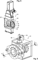
Fig. 1 zeigt in einer Vorderansicht einen als Flachplattenschieber ausgebildeten Absperrschieber 20, der in einer Hochofenperipherie an einen Anschlussstutzen 21 eines Hochofens 22 angeschlossen ist und den gasdichten Anschluss einer Messsonde 24 ermöglicht, die nach Überführung des Absperrschiebers 20 von seiner Absperrstellung in seine Öffnungsstellung durch eine insbesondere inFig. 4 dargestellte Durchgangsöffnung 43 einer Schieberplatte 32 in den Innenraum des Hochofens 22 eingeführt werden kann.Fig. 2 zeigt eine entsprechende Anordnung, bei der ein als Kalottenschieber ausgeführter Absperrschieber 25 an einen Anschlussstutzen 96 des Hochofens 22 angeschlossen ist, wobei der Absperrschieber 25 den gasdichten Anschluss einer auf einer Lafette 23 angeordneten Messsonde 97 ermöglicht. - Wie insbesondere aus einer Zusammenschau der
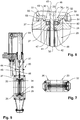
Fig. 3 bis 7 hervorgeht, weist der im vorliegenden Fall als Flachplattenschieber ausgeführte Absperrschieber 20 ein Schiebergehäuse 26 auf, das, wie insbesondereFig. 6 zeigt, zwischen zwei Gehäuseteilen 27, 28 eine Schieberführung 29 mit zwei Führungshälften 30, 31 aufweist, zwischen denen eine im Falle des hier dargestellten, als Flachplattenschieber ausgeführten Absperrschiebers 20 als ebene Platte ausgeführte Schieberplatte 32 angeordnet ist. - Wie insbesondere der
Fig. 6 zu entnehmen ist, weisen die Führungshälften 30, 31 jeweils ein Dichtungselement 33, 34 auf. Die Dichtungselemente 33, 34 sind im vorliegenden Fall als pneumatische Schlauchdichtungen ausgebildet und weisen daher einen Hohlraum 37 auf, der über eine Druckleitung 62 mit Gasdruck beaufschlagbar ist. - Neben den Dichtungselementen 33, 34 weisen die Führungshälften 30, 31 Abstreifer 41, 42 auf, welche bei einer Überführung der Schieberplatte 32 in ihre in den
Fig. 3 bis 7 dargestellte Öffnungsstellung etwaige an einem oberhalb der Durchgangsöffnung 43 auf einem Verschlussabschnitt 44 anhaftende Schmutzpartikel von Schieberblattflächen 45, 46 abstreifen, um die Dichtungselemente 33, 34 vor einer Beeinträchtigung durch Schmutzpartikel zu schützen. - Wie insbesondere
Fig. 6 zeigt, ermöglichen die Führungshälften 30, 31 im vorliegenden Fall darüber hinaus die Anordnung jeweils einer zur beidseitigen Abstützung gegen die Schieberblattflächen 45, 46 dienenden axialen Stützeinrichtung 47, 48, wobei die Stützeinrichtungen 47, 48 beispielsweise als PTFE-Ringe ausgeführt sein können. -
Fig. 6 zeigt, dass die Führungshälften 30, 31 jeweils einen Ringflansch 49, 50 aufweisen, die zur Ausbildung einer Klemmverbindung 51, 52 jeweils benachbart einem an dem angrenzenden Gehäuseteil 27, 28 ausgebildeten Ringflansch 53, 54 angeordnet sind, wobei die Ringflansche 49, 53 beziehungsweise 50, 54 in der dargestellten Relativanordnung durch jeweils zweiteilig ausgeführte Klemmringe 55, 56 gegeneinander verspannt sind. - Wie insbesondere aus
Fig. 8 ersichtlich ist, kann jede Führungshälfte 30, 31 nach Entfernung der jeweiligen Klemmverbindung 51, 52 (Fig. 6 ) durch Lösen von Bolzenverbindungen 59, die jeweils zwei Halbringe 57, 58 der Klemmringe 55, 56 miteinander verbindenden, Bezug nehmend auf eine Durchströmungsachse 60 des Absperrschiebers 20 radial dem Schiebergehäuses 26 entnommen werden, nachdem lediglich ein Seitendeckel 61 des Gehäuses entfernt worden ist. - Wie insbesondere aus einer Zusammenschau der
Fig. 1 und6 deutlich wird, kann zur Entfernung des Seitendeckels 61 und der nachfolgenden Demontage der Führungshälften 30, 31 der Schieberführung 29 der Absperrschieber 20 an Ort und Stelle in seiner Position am Anschlussstutzen 21 des Hochofens 22 verbleiben. -
Fig. 9 zeigt den in seiner Relativanordnung zu einem Hochofen 22 inFig. 2 dargestellten, hier als Kalottenschieber ausgeführten Absperrschieber 25 in isometrischer Darstellung. Wie insbesondere aus der Schnittdarstellung gemäßFig. 11 deutlich wird, weist der Absperrschieber 25 eine sphärisch ausgebildete, hier als Kalotte bezeichnete Schieberplatte 63 auf, die im Unterschied zu der als ebene Platte ausgeführten Schieberplatte 32 des Absperrschiebers 20 nicht mit einer translatorischen Antriebseinrichtung 64 (sieheFig. 5 ) zur translatorischen Überführung der Schieberplatte 32 von einer Öffnungsstellung in einer Absperrstellung und umgekehrt versehen ist, sondern einen Drehantrieb 65 (sieheFig. 9 und12 ) aufweist, der, wie inFig. 11 durch den Drehrichtungspfeil angedeutet, zur Überführung der Schieberplatte 63 aus der dargestellten Öffnungsstellung in eine Absperrstellung eine Drehbewegung um eine Schwenkachse 66 ausführt. - Wie
Fig. 11 zeigt, weist eine Schieberführung 67 des Absperrschiebers 25 zur Anpassung an die sphärische Ausgestaltung der Schieberplatte 63 zwei unterschiedlich ausgebildete Führungshälften 68, 69 auf, die jeweils zur Anordnung eines Dichtungselements 70, 71 einen Dichtungsträger 72, 73 aufweisen, die gleichzeitig zur Ausbildung einer axialen Stützeinrichtung dienen, derart, dass die Stützeinrichtungen eine Aufnahme für die Dichtungselemente 70, 71 ausbilden. - Entsprechend den Führungshälften 30, 31 des Absperrschiebers 20 sind auch die Führungshälften 68, 69 des Absperrschiebers 62 jeweils mit einem Abstreifer 74, 75 versehen. Zur Verbindung mit jeweils einem Gehäuseteil 76, 77 eines Schiebergehäuses 78 sind zwischen den Führungshälften 68, 69 und den Gehäuseteilen 76, 77 Klemmverbindungen 79vorgesehen, derart, dass die Gehäuseteile 76, 77 und die Führungshälften 68, 69 jeweils einander angrenzend mit Ringflanschen 81, 82 beziehungsweise 83, 84 versehen sind, welche, wie bereits zuvor bezugnehmend auf die
Fig. 6 und8 erläutert, über zweiteilige Klemmringe 85, 86 miteinander verspannt sind. - Zur Demontage der Führungshälften 68, 69 werden die Führungshälften 68, 69 und die zwischen den Führungshälften 68, 69 aufgenommene Schieberplatte 63 mittels einer temporären Montagesicherung 87 zu einer Montageeinheit 91 zusammengefasst, wobei die Montagesicherung 87 im vorliegenden Fall drei Bolzenverbindungen 88 umfasst, welche die Führungshälften 68, 69 mit der zwischenliegend angeordneten Schieberplatte 63, wie in den
Fig. 12 und 13 dargestellt, verspannen. Erst nach Ausführung der Montagesicherung 87 werden die Klemmverbindungen 79, 80 zwischen den Führungshälften 68, 69 und den Gehäuseteilen 76, 77 sowie eine zwischen dem Drehantrieb 65 und der Schieberplatte 63 ausgebildete Kupplung 94 gelöst. Anschließend kann die Montageeinheit 91, die über einen Mitnehmer 89 mit einer am Schiebergehäuse 78 angeordneten Montageschiene 90 verbunden ist, für den Monteur gewichtsentlastet radial zu einer Durchströmungsachse 95 des Absperrschiebers 25 dem Schiebergehäuse 78 entnommen werden. - Wie insbesondere den
Fig. 9 bis 11 zu entnehmen ist, ist das Schiebergehäuse 78 des Absperrschiebers 25 zum Anschluss an die inFig. 2 dargestellte Messsonde 24 mit einer Stopfbuchse 92 versehen, welche über einen Kompensator 93, der einen variablen Eintrittswinkel der Messsonde 24 durch die aus der Stopfbuchse 92 und dem Absperrschieber 25 gebildete Anordnung in den Hochofen 22 ermöglicht. WieFig. 1 zeigt, ist eine entsprechende Anordnung auch für den Absperrschieber 20 vorgesehen. - Aus dem Vorstehenden wird deutlich, dass der Austausch der mit den Dichtungselementen 33, 34 bzw. 70, 71 versehenen Schieberführungen 29 bzw. 67 sowohl an dem Absperrschieber 20 als auch an dem Absperrschieber 25 nicht nur unter Beibehaltung der installierten Position der Absperrschieber 20, 25 am Hochofen 22 erfolgen kann, sondern dass insbesondere auch eine Trennung der Schiebergehäuse 26, 78 der Absperrschieber 20, 25 von angeschlossenen Komponenten, wie hier insbesondere die jeweils über den Kompensator 93 an die Schiebergehäuse 26, 78 angeschlossene Stopfbuchsen 92 nicht erforderlich ist.
Claims (12)
- Absperrschieber (20, 25) mit einer in einem Schiebergehäuse (26, 78) in einer Schieberführung (29, 67) zwischen einer Absperrstellung und einer Öffnungsstellung bewegbaren Schieberplatte (32, 63), wobei die Schieberführung (29, 67) mit einer Schieberdichtung zur Erzielung einer gasdichten Absperrstellung versehen ist, wobei die Schieberführung (29, 67) über eine Flanschverbindung mit dem Schiebergehäuse (26, 78) verbunden ist,
dadurch gekennzeichnet,
dass die Schieberführung (29, 67) zwei Führungshälften (30, 31; 68, 69) umfasst, die jeweils mit einem zur Abdichtung gegen eine von zwei einander gegenüberliegenden Schieberblattflächen (45, 46) dienenden Dichtungselement (33, 34; 70, 71) der Schieberdichtung versehen sind, derart, dass die Schieberführung (29, 67) radial zu einer Durchströmungsachse (60, 95) des Absperrschiebers (20, 25) zusammen mit der Schieberdichtung dem Schiebergehäuse (26, 78) entnommen werden kann. - Absperrschieber nach Anspruch 1,
dadurch gekennzeichnet,
dass die Führungshälften (30, 31; 68, 69) jeweils eine axiale Stützeinrichtung (47, 48) zur beidseitigen Abstützung gegen die Schieberplattenflächen (45, 46) aufweisen. - Absperrschieber nach Anspruch 1 oder 2,
dadurch gekennzeichnet,
dass die Führungshälften (30, 31; 68, 69) an einer Gehäuseanschlussseite einen Ringflansch (49, 50; 83, 84) zur Ausbildung der Flanschverbindung als Klemmverbindung (51, 52; 79, 80) mit einem an einem Gehäuseteil (27, 28; 76, 77) des Schiebergehäuses (26, 78) ausgebildeten Ringflansch (53, 54; 81, 82) aufweisen. - Absperrschieber nach einem der vorangehenden Ansprüche,
dadurch gekennzeichnet,
dass die Führungshälften (30, 31) zur Anordnung des Dichtungselements (33, 34) einen Dichtungsträger aufweisen, der zur Verbindung mit einem Gehäuseteil (27, 28) des Schiebergehäuses (26) dient. - Absperrschieber nach einem der vorangehenden Ansprüche,
dadurch gekennzeichnet,
dass die Führungshälften (30, 31) unabhängig voneinander dem Schiebergehäuse (26) entnehmbar sind. - Absperrschieber nach einem der vorangehenden Ansprüche,
dadurch gekennzeichnet,
dass die Führungshälften (30, 31) unterschiedlich ausgebildet sind. - Absperrschieber nach einem der vorangehenden Ansprüche,
dadurch gekennzeichnet,
dass die Führungshälften (68, 69) als zusammenhängende Montageeinheit (91) dem Schiebergehäuse (78) entnehmbar sind. - Absperrschieber nach Anspruch 7,
dadurch gekennzeichnet,
dass die Schieberplatte (63) einen Bestandteil der Montageeinheit (91) ausbildet. - Absperrschieber nach Anspruch 8,
dadurch gekennzeichnet,
dass zur Ausbildung der Montageeinheit (91) die Führungshälften (68, 69) unter zwischenliegender Anordnung der Schieberplatte (63) mittels einer temporären Montagesicherung (87) miteinander verbunden sind. - Absperrschieber nach Anspruch 9,
dadurch gekennzeichnet,
dass zur Ausbildung der Montagesicherung (87) die Führungshälften (68, 69) mit axialen Spanneinrichtungen gegeneinander verspannt sind. - Absperrschieber nach Anspruch 10,
dadurch gekennzeichnet,
dass die Führungshälften (68, 69) unterschiedlich ausgebildet sind und die Schieberplatte (63) schalenförmig ausgebildet ist. - Absperrschieber nach Anspruch 11,
dadurch gekennzeichnet,
dass die Führungshälften (68, 69) zur Anordnung des Dichtungselements (70, 71) einen Dichtungsträger (72, 73) aufweisen, der gleichzeitig zur Ausbildung einer Stützeinrichtung dient, derart, dass die Stützeinrichtung eine Aufnahme für das Dichtungselement (70, 71) ausbildet.
Applications Claiming Priority (1)
| Application Number | Priority Date | Filing Date | Title |
|---|---|---|---|
| PCT/EP2017/078798 WO2019091563A1 (de) | 2017-11-09 | 2017-11-09 | Absperrschieber |
Publications (2)
| Publication Number | Publication Date |
|---|---|
| EP3707450A1 EP3707450A1 (de) | 2020-09-16 |
| EP3707450B1 true EP3707450B1 (de) | 2021-10-27 |
Family
ID=60574528
Family Applications (1)
| Application Number | Title | Priority Date | Filing Date |
|---|---|---|---|
| EP17808790.4A Active EP3707450B1 (de) | 2017-11-09 | 2017-11-09 | Absperrschieber |
Country Status (10)
| Country | Link |
|---|---|
| US (1) | US11306827B2 (de) |
| EP (1) | EP3707450B1 (de) |
| JP (1) | JP7037647B2 (de) |
| KR (1) | KR102354578B1 (de) |
| CN (1) | CN111344529B (de) |
| BR (1) | BR112020007599B1 (de) |
| CA (1) | CA3079274C (de) |
| RU (1) | RU2768902C2 (de) |
| UA (1) | UA127603C2 (de) |
| WO (1) | WO2019091563A1 (de) |
Cited By (1)
| Publication number | Priority date | Publication date | Assignee | Title |
|---|---|---|---|---|
| JP7037647B2 (ja) | 2017-11-09 | 2022-03-16 | ティエムティ - タッピング メジャーリング テクノロジー エスエイアールエル | スライドバルブ |
Families Citing this family (2)
| Publication number | Priority date | Publication date | Assignee | Title |
|---|---|---|---|---|
| USD1047328S1 (en) * | 2021-12-22 | 2024-10-15 | Woodpeckers, Llc | Blast gate |
| GB2641061A (en) * | 2024-05-14 | 2025-11-19 | Woodward Peter | Valve |
Family Cites Families (15)
| Publication number | Priority date | Publication date | Assignee | Title |
|---|---|---|---|---|
| US384849A (en) * | 1888-06-19 | Harbison p | ||
| US1874627A (en) * | 1930-07-01 | 1932-08-30 | Fred E Riley | Gate valve with nonplugging seat constructions |
| US4444214A (en) * | 1981-05-18 | 1984-04-24 | Continental Disc Corporation | Replaceable rupture disc cartridge arrangement |
| ATE99396T1 (de) * | 1989-11-08 | 1994-01-15 | Cooper Ind Inc | Ventil mit auswechselbarem einsatzstueck. |
| DE4000139C3 (de) | 1990-01-04 | 1997-03-13 | Schuette Meyer Schuettgutabspe | Flachschieber, insbes. Schüttgutschieber |
| US6497245B1 (en) * | 1999-10-13 | 2002-12-24 | Denso Corporation | Intake air controller for internal combustion engine and manufacturing the same |
| US6220282B1 (en) * | 1999-11-03 | 2001-04-24 | Hunter Innovations, Inc. | Backflow prevention apparatus |
| CN2403961Y (zh) | 2000-01-25 | 2000-11-01 | 姜立 | 平行板阀 |
| DE10053850A1 (de) * | 2000-10-30 | 2002-05-08 | Bosch Gmbh Robert | Exzenterventil |
| RU2350814C1 (ru) * | 2007-07-25 | 2009-03-27 | Геннадий Гаврилович Плотников | Шиберная задвижка |
| RU2467235C2 (ru) * | 2010-05-31 | 2012-11-20 | Общество с ограниченной ответственностью "Научно Производственная Фирма Кубаньнефтемаш" | Задвижка шиберная |
| PL2994673T3 (pl) | 2013-05-07 | 2018-05-30 | Victaulic Company | Zawór z dającym się usunąć gniazdem |
| EP3405707B1 (de) | 2016-01-22 | 2021-02-24 | Oxo Fab Inc. | Plattenschieber |
| CN206017821U (zh) | 2016-08-26 | 2017-03-15 | 江苏苏盐阀门机械有限公司 | 一种新型平板阀 |
| JP7037647B2 (ja) | 2017-11-09 | 2022-03-16 | ティエムティ - タッピング メジャーリング テクノロジー エスエイアールエル | スライドバルブ |
-
2017
- 2017-11-09 JP JP2020520159A patent/JP7037647B2/ja active Active
- 2017-11-09 WO PCT/EP2017/078798 patent/WO2019091563A1/de not_active Ceased
- 2017-11-09 US US16/754,908 patent/US11306827B2/en not_active Expired - Fee Related
- 2017-11-09 KR KR1020207010948A patent/KR102354578B1/ko active Active
- 2017-11-09 RU RU2020117181A patent/RU2768902C2/ru active
- 2017-11-09 CA CA3079274A patent/CA3079274C/en active Active
- 2017-11-09 BR BR112020007599-0A patent/BR112020007599B1/pt active IP Right Grant
- 2017-11-09 CN CN201780096487.XA patent/CN111344529B/zh active Active
- 2017-11-09 EP EP17808790.4A patent/EP3707450B1/de active Active
- 2017-11-09 UA UAA202003181A patent/UA127603C2/uk unknown
Cited By (1)
| Publication number | Priority date | Publication date | Assignee | Title |
|---|---|---|---|---|
| JP7037647B2 (ja) | 2017-11-09 | 2022-03-16 | ティエムティ - タッピング メジャーリング テクノロジー エスエイアールエル | スライドバルブ |
Also Published As
| Publication number | Publication date |
|---|---|
| UA127603C2 (uk) | 2023-11-01 |
| JP2021502522A (ja) | 2021-01-28 |
| KR20200081365A (ko) | 2020-07-07 |
| RU2768902C2 (ru) | 2022-03-25 |
| BR112020007599A2 (pt) | 2020-09-29 |
| RU2020117181A (ru) | 2021-12-10 |
| CA3079274C (en) | 2023-08-01 |
| JP7037647B2 (ja) | 2022-03-16 |
| RU2020117181A3 (de) | 2021-12-10 |
| CN111344529B (zh) | 2022-07-12 |
| WO2019091563A1 (de) | 2019-05-16 |
| BR112020007599B1 (pt) | 2022-07-26 |
| US20200263794A1 (en) | 2020-08-20 |
| EP3707450A1 (de) | 2020-09-16 |
| KR102354578B1 (ko) | 2022-01-24 |
| US11306827B2 (en) | 2022-04-19 |
| CA3079274A1 (en) | 2019-05-16 |
| CN111344529A (zh) | 2020-06-26 |
Similar Documents
| Publication | Publication Date | Title |
|---|---|---|
| DE3828693C1 (de) | ||
| EP3749861B2 (de) | Exzenterschneckenpumpe | |
| EP0658501A1 (de) | Vorrichtung zum Kuppeln von Behältnissen | |
| DE3014874A1 (de) | Absperrventil | |
| DE102011015062A1 (de) | Filtergehäuse eines Luftfilters und Verschlusselement eines Filtergehäuses | |
| DE102011121281A1 (de) | Maul- oder klauenförmige Spaltdichtung | |
| DE19520409C1 (de) | Vorrichtung zum Kuppeln von Behältnissen mit Blas- und Absaugeinrichtung | |
| EP3707450A1 (de) | Absperrschieber | |
| EP3017933B1 (de) | Vorrichtung zum laserauftragsschweissen zur additiven fertigung dreidimensionaler objekte | |
| DE2014481A1 (de) | Vorrichtung und Verfahren zum Einsetzen von Ventilen zwischen die Flansche einer Flanschenrohrverbindung | |
| DE3874668T2 (de) | Vorrichtung zur entkuppelbaren verbindung zweier dichter hohlraeume. | |
| DE2814486A1 (de) | Drehschieber zur steuerung der stroemung eines festen, teilchenfoermigen materials | |
| WO2007065552A1 (de) | Greifvorrichtung für einen roboter oder einen portallader | |
| DE202011109164U1 (de) | Maul- oder klauenförmige Spaltdichtung | |
| WO2005108079A1 (de) | Druckmaschine mit drehübertrager zum einführen eines flüssigen oder gasförmigen mediums | |
| EP2193092B1 (de) | Andockeinrichtung aus zwei kupplungsverschlüssen zum umweltdichten transfer von schüttgut, enthaltend mindestens eine verriegelungseinheit | |
| DE10316673A1 (de) | Vorrichtung zum Ankuppeln einer Kühlmittelzuführung an eine Walze | |
| DE10230396B4 (de) | Arbeitskammer | |
| EP2113650B1 (de) | Luftfiltergehäuse mit schwenkbarer Reinlufthaube | |
| DE202009018738U1 (de) | Leicht lösbares Kupplungssystem zur axialen Kupplung von zwei Flanschen | |
| DE102009054425A1 (de) | Abzieheinrichtung zum Abziehen von Elektrodenkappen von Schweißelektroden | |
| DE2529138A1 (de) | Flansch-platten-anordnung, sowie verfahren zu deren herstellung | |
| WO2001053176A1 (de) | Verfahren und vorrichtung zum koppeln von behältern und/oder leitungen | |
| EP0305549B1 (de) | Kammer zum entzundern von flachstahl mit schleifpulver | |
| DE202018101406U1 (de) | Drehauswerfer für Fördergut |
Legal Events
| Date | Code | Title | Description |
|---|---|---|---|
| STAA | Information on the status of an ep patent application or granted ep patent |
Free format text: STATUS: UNKNOWN |
|
| STAA | Information on the status of an ep patent application or granted ep patent |
Free format text: STATUS: THE INTERNATIONAL PUBLICATION HAS BEEN MADE |
|
| PUAI | Public reference made under article 153(3) epc to a published international application that has entered the european phase |
Free format text: ORIGINAL CODE: 0009012 |
|
| STAA | Information on the status of an ep patent application or granted ep patent |
Free format text: STATUS: REQUEST FOR EXAMINATION WAS MADE |
|
| 17P | Request for examination filed |
Effective date: 20200512 |
|
| AK | Designated contracting states |
Kind code of ref document: A1 Designated state(s): AL AT BE BG CH CY CZ DE DK EE ES FI FR GB GR HR HU IE IS IT LI LT LU LV MC MK MT NL NO PL PT RO RS SE SI SK SM TR |
|
| AX | Request for extension of the european patent |
Extension state: BA ME |
|
| DAV | Request for validation of the european patent (deleted) | ||
| DAX | Request for extension of the european patent (deleted) | ||
| REG | Reference to a national code |
Ref country code: DE Ref legal event code: R079 Ref document number: 502017011852 Country of ref document: DE Free format text: PREVIOUS MAIN CLASS: F27B0001100000 Ipc: F16K0031520000 |
|
| GRAP | Despatch of communication of intention to grant a patent |
Free format text: ORIGINAL CODE: EPIDOSNIGR1 |
|
| STAA | Information on the status of an ep patent application or granted ep patent |
Free format text: STATUS: GRANT OF PATENT IS INTENDED |
|
| RIC1 | Information provided on ipc code assigned before grant |
Ipc: F16K 27/04 20060101ALI20210416BHEP Ipc: F16K 3/20 20060101ALI20210416BHEP Ipc: F16K 3/02 20060101ALI20210416BHEP Ipc: F27B 1/10 20060101ALI20210416BHEP Ipc: F16K 3/22 20060101ALI20210416BHEP Ipc: F16K 31/52 20060101AFI20210416BHEP |
|
| INTG | Intention to grant announced |
Effective date: 20210518 |
|
| RIN1 | Information on inventor provided before grant (corrected) |
Inventor name: HUTMACHER, PATRICK Inventor name: STEICHEN, CHARLES |
|
| GRAS | Grant fee paid |
Free format text: ORIGINAL CODE: EPIDOSNIGR3 |
|
| GRAA | (expected) grant |
Free format text: ORIGINAL CODE: 0009210 |
|
| STAA | Information on the status of an ep patent application or granted ep patent |
Free format text: STATUS: THE PATENT HAS BEEN GRANTED |
|
| AK | Designated contracting states |
Kind code of ref document: B1 Designated state(s): AL AT BE BG CH CY CZ DE DK EE ES FI FR GB GR HR HU IE IS IT LI LT LU LV MC MK MT NL NO PL PT RO RS SE SI SK SM TR |
|
| REG | Reference to a national code |
Ref country code: GB Ref legal event code: FG4D Free format text: NOT ENGLISH |
|
| REG | Reference to a national code |
Ref country code: CH Ref legal event code: EP |
|
| REG | Reference to a national code |
Ref country code: DE Ref legal event code: R096 Ref document number: 502017011852 Country of ref document: DE |
|
| REG | Reference to a national code |
Ref country code: AT Ref legal event code: REF Ref document number: 1442083 Country of ref document: AT Kind code of ref document: T Effective date: 20211115 |
|
| REG | Reference to a national code |
Ref country code: IE Ref legal event code: FG4D Free format text: LANGUAGE OF EP DOCUMENT: GERMAN |
|
| REG | Reference to a national code |
Ref country code: NL Ref legal event code: FP |
|
| REG | Reference to a national code |
Ref country code: LT Ref legal event code: MG9D |
|
| PG25 | Lapsed in a contracting state [announced via postgrant information from national office to epo] |
Ref country code: RS Free format text: LAPSE BECAUSE OF FAILURE TO SUBMIT A TRANSLATION OF THE DESCRIPTION OR TO PAY THE FEE WITHIN THE PRESCRIBED TIME-LIMIT Effective date: 20211027 Ref country code: LT Free format text: LAPSE BECAUSE OF FAILURE TO SUBMIT A TRANSLATION OF THE DESCRIPTION OR TO PAY THE FEE WITHIN THE PRESCRIBED TIME-LIMIT Effective date: 20211027 Ref country code: FI Free format text: LAPSE BECAUSE OF FAILURE TO SUBMIT A TRANSLATION OF THE DESCRIPTION OR TO PAY THE FEE WITHIN THE PRESCRIBED TIME-LIMIT Effective date: 20211027 Ref country code: BG Free format text: LAPSE BECAUSE OF FAILURE TO SUBMIT A TRANSLATION OF THE DESCRIPTION OR TO PAY THE FEE WITHIN THE PRESCRIBED TIME-LIMIT Effective date: 20220127 |
|
| PG25 | Lapsed in a contracting state [announced via postgrant information from national office to epo] |
Ref country code: IS Free format text: LAPSE BECAUSE OF FAILURE TO SUBMIT A TRANSLATION OF THE DESCRIPTION OR TO PAY THE FEE WITHIN THE PRESCRIBED TIME-LIMIT Effective date: 20220227 Ref country code: SE Free format text: LAPSE BECAUSE OF FAILURE TO SUBMIT A TRANSLATION OF THE DESCRIPTION OR TO PAY THE FEE WITHIN THE PRESCRIBED TIME-LIMIT Effective date: 20211027 Ref country code: PT Free format text: LAPSE BECAUSE OF FAILURE TO SUBMIT A TRANSLATION OF THE DESCRIPTION OR TO PAY THE FEE WITHIN THE PRESCRIBED TIME-LIMIT Effective date: 20220228 Ref country code: PL Free format text: LAPSE BECAUSE OF FAILURE TO SUBMIT A TRANSLATION OF THE DESCRIPTION OR TO PAY THE FEE WITHIN THE PRESCRIBED TIME-LIMIT Effective date: 20211027 Ref country code: NO Free format text: LAPSE BECAUSE OF FAILURE TO SUBMIT A TRANSLATION OF THE DESCRIPTION OR TO PAY THE FEE WITHIN THE PRESCRIBED TIME-LIMIT Effective date: 20220127 Ref country code: LV Free format text: LAPSE BECAUSE OF FAILURE TO SUBMIT A TRANSLATION OF THE DESCRIPTION OR TO PAY THE FEE WITHIN THE PRESCRIBED TIME-LIMIT Effective date: 20211027 Ref country code: HR Free format text: LAPSE BECAUSE OF FAILURE TO SUBMIT A TRANSLATION OF THE DESCRIPTION OR TO PAY THE FEE WITHIN THE PRESCRIBED TIME-LIMIT Effective date: 20211027 Ref country code: GR Free format text: LAPSE BECAUSE OF FAILURE TO SUBMIT A TRANSLATION OF THE DESCRIPTION OR TO PAY THE FEE WITHIN THE PRESCRIBED TIME-LIMIT Effective date: 20220128 Ref country code: ES Free format text: LAPSE BECAUSE OF FAILURE TO SUBMIT A TRANSLATION OF THE DESCRIPTION OR TO PAY THE FEE WITHIN THE PRESCRIBED TIME-LIMIT Effective date: 20211027 |
|
| REG | Reference to a national code |
Ref country code: CH Ref legal event code: PL |
|
| REG | Reference to a national code |
Ref country code: DE Ref legal event code: R097 Ref document number: 502017011852 Country of ref document: DE |
|
| PG25 | Lapsed in a contracting state [announced via postgrant information from national office to epo] |
Ref country code: SM Free format text: LAPSE BECAUSE OF FAILURE TO SUBMIT A TRANSLATION OF THE DESCRIPTION OR TO PAY THE FEE WITHIN THE PRESCRIBED TIME-LIMIT Effective date: 20211027 Ref country code: SK Free format text: LAPSE BECAUSE OF FAILURE TO SUBMIT A TRANSLATION OF THE DESCRIPTION OR TO PAY THE FEE WITHIN THE PRESCRIBED TIME-LIMIT Effective date: 20211027 Ref country code: RO Free format text: LAPSE BECAUSE OF FAILURE TO SUBMIT A TRANSLATION OF THE DESCRIPTION OR TO PAY THE FEE WITHIN THE PRESCRIBED TIME-LIMIT Effective date: 20211027 Ref country code: MC Free format text: LAPSE BECAUSE OF FAILURE TO SUBMIT A TRANSLATION OF THE DESCRIPTION OR TO PAY THE FEE WITHIN THE PRESCRIBED TIME-LIMIT Effective date: 20211027 Ref country code: EE Free format text: LAPSE BECAUSE OF FAILURE TO SUBMIT A TRANSLATION OF THE DESCRIPTION OR TO PAY THE FEE WITHIN THE PRESCRIBED TIME-LIMIT Effective date: 20211027 Ref country code: DK Free format text: LAPSE BECAUSE OF FAILURE TO SUBMIT A TRANSLATION OF THE DESCRIPTION OR TO PAY THE FEE WITHIN THE PRESCRIBED TIME-LIMIT Effective date: 20211027 Ref country code: BE Free format text: LAPSE BECAUSE OF NON-PAYMENT OF DUE FEES Effective date: 20211130 |
|
| REG | Reference to a national code |
Ref country code: BE Ref legal event code: MM Effective date: 20211130 |
|
| PLBE | No opposition filed within time limit |
Free format text: ORIGINAL CODE: 0009261 |
|
| STAA | Information on the status of an ep patent application or granted ep patent |
Free format text: STATUS: NO OPPOSITION FILED WITHIN TIME LIMIT |
|
| 26N | No opposition filed |
Effective date: 20220728 |
|
| PG25 | Lapsed in a contracting state [announced via postgrant information from national office to epo] |
Ref country code: IE Free format text: LAPSE BECAUSE OF NON-PAYMENT OF DUE FEES Effective date: 20211109 Ref country code: AL Free format text: LAPSE BECAUSE OF FAILURE TO SUBMIT A TRANSLATION OF THE DESCRIPTION OR TO PAY THE FEE WITHIN THE PRESCRIBED TIME-LIMIT Effective date: 20211027 |
|
| PG25 | Lapsed in a contracting state [announced via postgrant information from national office to epo] |
Ref country code: SI Free format text: LAPSE BECAUSE OF FAILURE TO SUBMIT A TRANSLATION OF THE DESCRIPTION OR TO PAY THE FEE WITHIN THE PRESCRIBED TIME-LIMIT Effective date: 20211027 |
|
| PGFP | Annual fee paid to national office [announced via postgrant information from national office to epo] |
Ref country code: TR Payment date: 20221107 Year of fee payment: 6 Ref country code: IT Payment date: 20221130 Year of fee payment: 6 |
|
| PG25 | Lapsed in a contracting state [announced via postgrant information from national office to epo] |
Ref country code: CY Free format text: LAPSE BECAUSE OF FAILURE TO SUBMIT A TRANSLATION OF THE DESCRIPTION OR TO PAY THE FEE WITHIN THE PRESCRIBED TIME-LIMIT Effective date: 20211027 |
|
| PG25 | Lapsed in a contracting state [announced via postgrant information from national office to epo] |
Ref country code: LI Free format text: LAPSE BECAUSE OF NON-PAYMENT OF DUE FEES Effective date: 20220701 Ref country code: HU Free format text: LAPSE BECAUSE OF FAILURE TO SUBMIT A TRANSLATION OF THE DESCRIPTION OR TO PAY THE FEE WITHIN THE PRESCRIBED TIME-LIMIT; INVALID AB INITIO Effective date: 20171109 Ref country code: CH Free format text: LAPSE BECAUSE OF NON-PAYMENT OF DUE FEES Effective date: 20220701 |
|
| PGFP | Annual fee paid to national office [announced via postgrant information from national office to epo] |
Ref country code: FR Payment date: 20231122 Year of fee payment: 7 Ref country code: CZ Payment date: 20231027 Year of fee payment: 7 |
|
| PG25 | Lapsed in a contracting state [announced via postgrant information from national office to epo] |
Ref country code: MK Free format text: LAPSE BECAUSE OF FAILURE TO SUBMIT A TRANSLATION OF THE DESCRIPTION OR TO PAY THE FEE WITHIN THE PRESCRIBED TIME-LIMIT Effective date: 20211027 |
|
| PG25 | Lapsed in a contracting state [announced via postgrant information from national office to epo] |
Ref country code: MT Free format text: LAPSE BECAUSE OF FAILURE TO SUBMIT A TRANSLATION OF THE DESCRIPTION OR TO PAY THE FEE WITHIN THE PRESCRIBED TIME-LIMIT Effective date: 20211027 |
|
| PG25 | Lapsed in a contracting state [announced via postgrant information from national office to epo] |
Ref country code: IT Free format text: LAPSE BECAUSE OF NON-PAYMENT OF DUE FEES Effective date: 20231109 |
|
| PGFP | Annual fee paid to national office [announced via postgrant information from national office to epo] |
Ref country code: LU Payment date: 20241119 Year of fee payment: 8 Ref country code: NL Payment date: 20241120 Year of fee payment: 8 |
|
| PG25 | Lapsed in a contracting state [announced via postgrant information from national office to epo] |
Ref country code: IT Free format text: LAPSE BECAUSE OF NON-PAYMENT OF DUE FEES Effective date: 20231109 |
|
| PGFP | Annual fee paid to national office [announced via postgrant information from national office to epo] |
Ref country code: GB Payment date: 20241121 Year of fee payment: 8 |
|
| PGFP | Annual fee paid to national office [announced via postgrant information from national office to epo] |
Ref country code: AT Payment date: 20241118 Year of fee payment: 8 |
|
| PG25 | Lapsed in a contracting state [announced via postgrant information from national office to epo] |
Ref country code: CZ Free format text: LAPSE BECAUSE OF NON-PAYMENT OF DUE FEES Effective date: 20241109 |
|
| PG25 | Lapsed in a contracting state [announced via postgrant information from national office to epo] |
Ref country code: FR Free format text: LAPSE BECAUSE OF NON-PAYMENT OF DUE FEES Effective date: 20241130 |
|
| PGFP | Annual fee paid to national office [announced via postgrant information from national office to epo] |
Ref country code: DE Payment date: 20260119 Year of fee payment: 9 |
|
| PG25 | Lapsed in a contracting state [announced via postgrant information from national office to epo] |
Ref country code: TR Free format text: LAPSE BECAUSE OF NON-PAYMENT OF DUE FEES Effective date: 20231109 |
|
| REG | Reference to a national code |
Ref country code: NL Ref legal event code: MM Effective date: 20251201 |
|
| PG25 | Lapsed in a contracting state [announced via postgrant information from national office to epo] |
Ref country code: AT Free format text: LAPSE BECAUSE OF NON-PAYMENT OF DUE FEES Effective date: 20251109 |
|
| REG | Reference to a national code |
Ref country code: AT Ref legal event code: MM01 Ref document number: 1442083 Country of ref document: AT Kind code of ref document: T Effective date: 20251109 |
|
| PG25 | Lapsed in a contracting state [announced via postgrant information from national office to epo] |
Ref country code: LU Free format text: LAPSE BECAUSE OF NON-PAYMENT OF DUE FEES Effective date: 20251109 |