EP3706952B1 - Method for machining a glass pane - Google Patents
Method for machining a glass pane Download PDFInfo
- Publication number
- EP3706952B1 EP3706952B1 EP18795572.9A EP18795572A EP3706952B1 EP 3706952 B1 EP3706952 B1 EP 3706952B1 EP 18795572 A EP18795572 A EP 18795572A EP 3706952 B1 EP3706952 B1 EP 3706952B1
- Authority
- EP
- European Patent Office
- Prior art keywords
- glass pane
- variable
- grinding tool
- offset
- edge
- Prior art date
- Legal status (The legal status is an assumption and is not a legal conclusion. Google has not performed a legal analysis and makes no representation as to the accuracy of the status listed.)
- Active
Links
Images


Classifications
-
- B—PERFORMING OPERATIONS; TRANSPORTING
- B24—GRINDING; POLISHING
- B24B—MACHINES, DEVICES, OR PROCESSES FOR GRINDING OR POLISHING; DRESSING OR CONDITIONING OF ABRADING SURFACES; FEEDING OF GRINDING, POLISHING, OR LAPPING AGENTS
- B24B49/00—Measuring or gauging equipment for controlling the feed movement of the grinding tool or work; Arrangements of indicating or measuring equipment, e.g. for indicating the start of the grinding operation
- B24B49/10—Measuring or gauging equipment for controlling the feed movement of the grinding tool or work; Arrangements of indicating or measuring equipment, e.g. for indicating the start of the grinding operation involving electrical means
-
- B—PERFORMING OPERATIONS; TRANSPORTING
- B24—GRINDING; POLISHING
- B24B—MACHINES, DEVICES, OR PROCESSES FOR GRINDING OR POLISHING; DRESSING OR CONDITIONING OF ABRADING SURFACES; FEEDING OF GRINDING, POLISHING, OR LAPPING AGENTS
- B24B49/00—Measuring or gauging equipment for controlling the feed movement of the grinding tool or work; Arrangements of indicating or measuring equipment, e.g. for indicating the start of the grinding operation
- B24B49/16—Measuring or gauging equipment for controlling the feed movement of the grinding tool or work; Arrangements of indicating or measuring equipment, e.g. for indicating the start of the grinding operation taking regard of the load
-
- B—PERFORMING OPERATIONS; TRANSPORTING
- B24—GRINDING; POLISHING
- B24B—MACHINES, DEVICES, OR PROCESSES FOR GRINDING OR POLISHING; DRESSING OR CONDITIONING OF ABRADING SURFACES; FEEDING OF GRINDING, POLISHING, OR LAPPING AGENTS
- B24B9/00—Machines or devices designed for grinding edges or bevels on work or for removing burrs; Accessories therefor
- B24B9/02—Machines or devices designed for grinding edges or bevels on work or for removing burrs; Accessories therefor characterised by a special design with respect to properties of materials specific to articles to be ground
- B24B9/06—Machines or devices designed for grinding edges or bevels on work or for removing burrs; Accessories therefor characterised by a special design with respect to properties of materials specific to articles to be ground of non-metallic inorganic material, e.g. stone, ceramics, porcelain
- B24B9/08—Machines or devices designed for grinding edges or bevels on work or for removing burrs; Accessories therefor characterised by a special design with respect to properties of materials specific to articles to be ground of non-metallic inorganic material, e.g. stone, ceramics, porcelain of glass
- B24B9/10—Machines or devices designed for grinding edges or bevels on work or for removing burrs; Accessories therefor characterised by a special design with respect to properties of materials specific to articles to be ground of non-metallic inorganic material, e.g. stone, ceramics, porcelain of glass of plate glass
- B24B9/107—Machines or devices designed for grinding edges or bevels on work or for removing burrs; Accessories therefor characterised by a special design with respect to properties of materials specific to articles to be ground of non-metallic inorganic material, e.g. stone, ceramics, porcelain of glass of plate glass for glass plates while they are turning
Definitions
- the present invention relates to a method for machining a glass pane, wherein the edge of the glass pane is machined using at least one grinding tool, in that the glass pane and the grinding tool are moved relative to one another.
- the patent application JP 2007 136632 A describes a method, in which the parallel longitudinal sides of a glass sheet are ground by means of two grinding wheels. The currents flowing in the driving motors are shown on a display device in form of two waveforms. There are no measures provided to rectify the problem mentioned above of inaccurate machining due to inaccurate information on the position of the glass pane.
- An object of the present invention is to provide a method that allows precise machining of the edge of a glass pane.
- the offset of the glass pane with respect to a target position can be determined by detecting and evaluating a variable that is a function of the power consumption of the motor used to drive the grinding tool. This allows correction of a possible offset and precise grinding of the glass panes. For example, the current of the motor may be used as such a variable.
- configuring the device for machining a new glass pane shape is simplified, and series production may be monitored to ensure that the ground edges have the desired quality.
- the method according to the invention allows a precise machining of any shape of the glass pane, not only a rectangular shape, but any shape, i.e. a shape having a contour composed of straight and/or curved sections.
- the glass pane to be machined may be e.g. placed on a support to define the actual position. The latter may deviate from the target position by an offset.
- the offset may be considered as a displacement in the plane P defined by the backside of the glass pane.
- the displacement may be a linear and/or rotational one.
- the offset of the glass pane is defined by one or more of the following parameters:
- At least one of the following conditions is met:
- At least one of the three parameters mentioned above is determined in the method by detecting and evaluating the variable being a function of the power consumption of the motor used to drive the grinding tool.
- the variable being a function of the power consumption of the motor used to drive the grinding tool.
- it is not necessary to determine all of said parameters. This may be e.g. the case when one or more parameters is/are less dominant than another one.
- the rotation between the actual and target position may be small and therefore negligible and/or the shift between the actual and target position may tend to be greater along a particular axis than along another axis.
- the offset is determined in units of length and/or in angular units. This may be achieved e.g. by calibration measurements.
- the offset is determined by calculations performed by means of a controller.
- the latter may be provided with a program configured to calculate the offset.
- the calculations may include fitting a mathematical model to the detected curves values of the variable, averaging at least some of the detected values of the variable, taking into account values obtained from calibration measurements, etc.
- the determined offset is taken into account in a subsequent cycle of machining.
- the same glass pane may be machined at least once more and/or another glass pane may be machined.
- a correction is determined which adjusts the actual position of the glass pane to the target position.
- the correction may be taken into account in a subsequent cycle of machining.
- the complete circumferential edge of the glass pane is machined using one or more grinding tools.
- Fig. 1 schematically shows a device that is used for machining a glass pane edge.
- the edge is the circumferential outer area between the top side and the bottom side of the pane.
- the device includes a support 9 on which a glass pane rests during machining, a grinding tool 10 that may be set in rotation by means of an electric motor, for example a spindle motor, and a controller 15.
- An asynchronous motor or synchronous motor, for example, is suitable as an electric motor.
- the grinding tool 10 is designed, for example, as a one- or multi-part grinding disk.
- the support 9 and the grinding tool 10 are movable relative to one another so that an edge of the glass pane may be ground. This is achievable in various ways, for example as follows:
- a corresponding suitable drive and optionally a guide are provided.
- the grinding tool 10 is delivered by means of the drive, for example by path control.
- the grinding tool 10 then follows a fixed, predefined path. It is also conceivable for the grinding tool to be delivered in some other way, for example by force control or by path control and force control.
- Fig. 2 shows by way of example a device having a rotary table 8 that is rotatable about a center of rotation, as indicated by the double arrow 8a, and a grinding tool 10 that is movable back and forth along a linear axis, as indicated by the double arrow 10a.
- the rotary table 8 includes a support 9 in the form of one or more suction units on which a glass pane rests during the machining, and by means of which the glass pane is securely held.
- Fig. 2 also shows a controller 15 and an electric motor 11 for driving the grinding tool 10.
- the grinding tool together with the electric motor 11 is situated on a carriage 12 that is displaceable along a track 13 as a guide.
- a glass pane 1' which is in the actual position is also illustrated.
- the controller 15 has information concerning the desired shape of the glass pane 1', but does not necessarily know the exact location of the glass pane.
- the glass pane 1 in Fig. 1 represents the target position thereof, on the basis of which the controller 15 determines the movement of the support 9 and/or of the grinding tool 10 so that the glass pane edge 1a would be ground in the target position. It is apparent in Fig. 1 that the actual position and the target position are offset relative to one another. An offset may result from a displacement in the plane and/or from a rotation in the plane. In Fig.
- the x axis and y axis define the coordinate system in which the glass pane edge 1a is specified in the target position, while the x' axis and y' axis define the coordinate system in which the glass pane edge 1a' is provided in the actual position.
- the x'-y' coordinate system is displaced relative to the x-y coordinate system by the vector a ⁇ , and is rotated by an angle ⁇ .
- the electrical power consumption of the electric motor 11 while driving the grinding tool 10 is a function only of predefined process parameters, for example the pane shape, grinding speed, delivery, etc. During grinding along an essentially straight path, for example, the power consumption is essentially constant.
- the inventors have now found that an offset results in a corresponding variation in the power consumption.
- Conclusions concerning the offset may thus be drawn by detecting and evaluating a variable that corresponds to the power consumption.
- the current required by the electric motor 11 for driving the grinding tool 10 may be used as a variable that reflects the power consumption.
- the controller 15 is used to control the movement of the support 9 and/or the grinding tool 10, as well as the electric motor 11.
- the controller 15 is provided with a suitable program for evaluating the detected variable.
- the current value of the electric motor 11 and/or some other variable is detected which is a function of the power consumption.
- the position of the grinding tool 10 on the linear axis, and optionally further parameters, for example for force-controlled delivery, are recorded.
- the current is used as the variable to be detected. It is conceivable to use some other electrical variable, for example the voltage or a combination of current and voltage.
- Fig. 3 shows an example of a detected current curve I.
- the ordinate is the current, for example in units of amperes, and the values on the abscissa correspond to the position at the circumference of the glass pane 1a.
- the current value is recurrently detected after a displacement in the position. This results in a number N of measured values. (In the example according to Fig. 3 , this corresponds to approximately 450 measured values. Of course, N may also be different.)
- the measured values are processed in a first step.
- Current dips may occur, as is apparent in Fig. 3 .
- the current dip at the beginning and at the end of the measurement arises from the path plan of the grinding operation.
- the measurement begins with the recording of the values while the grinding tool 10 is still moving toward or away from the glass pane 1'.
- the stated start and end points of the measurement are between the two values having the smallest interval between them. All preceding and subsequent measured values are no longer used in the steps that follow for determining the offset. However, the value of the current required by the grinding tool 10 in idle mode, i.e., without contact with the glass pane 1', may be determined from the omitted measured values.
- the glass pane has a shape according to Fig. 1 ; i.e., it has four rounded corners that are defined by an external radius.
- the direction in which the edge extends, viewed in the top view of the glass pane 1' changes by more than a predefined angular value, for example by more than 45 degrees.
- the grinding tool 10 is grinding in each case during such a change in direction, it has a small support surface, so that almost no glass removal results and the current drops markedly.
- the calculated grinding speed behaves in a complementary manner during the stated changes in direction; i.e., it increases greatly during the current dips.
- the grinding speed v corresponding to the current curve I according to Fig. 3 is illustrated in units of length per unit time (in the present case, millimeters per 20 milliseconds).
- the bottom curve in Fig. 4 shows the derivative v' of the grinding speed v.
- the program uses, for example, the ratio of the spindle current I to the grinding speed v for filtering out the mentioned further current dips.
- the derivative v' at the locations of the stated changes in direction has positive and negative outliers.
- Current measured values for which the value of the derivative v' is above or below a predefined limit value (for example, ⁇ 0.25 in the example in Fig. 4 ) are declared as current dips, and are omitted for the further evaluation or are adjusted, for example by setting them to the average value of the detected current.
- the offset may be determined after the current measured values are processed.
- the offset is definable by three parameters: two parameters for a linear displacement in the plane (for example, the x and y values of the displacement vector a ⁇ ) and one parameter for the rotation ⁇ in the plane.
- two parameters for a linear displacement in the plane for example, the x and y values of the displacement vector a ⁇
- one parameter for the rotation ⁇ in the plane Various methods are conceivable for determining the offset from the plurality of current measured values, for example by fitting a mathematical model to the measuring curves, iteration, etc.
- a weighting function is determined in each case by forming the derivative and normalization to ⁇ 1.
- Fig. 5(a) and Fig. 5(b) show an example of this weighting function for the x and y directions in the case of a rectangular glass pane 1. In each case here, one side of the rectangle has no effect, while the other side has a maximum effect.
- Fig. 5(c) shows the weighting function for the angle that is obtained by forming the derivative of the absolute value of the vector based on the stated values for the x and y coordinates of the glass pane edge 1a.
- the effect is greatest in each case at the corners of the rectangle. In the center of a rectangle side the effect is equal to zero in each case, since the vector is then directed at 90 degrees with respect to the side.
- the current measured values I are reduced by the current value averaged over the entire measurement and multiplied by the weighting function for the x and y directions.
- the curves illustrated in Fig. 6(a) and Fig. 6(b) are obtained.
- the offset in the x and y directions is obtained, in units of amperes per measured value, by averaging the values.
- the offset in the x direction is zero, and in the y direction the offset corresponds approximately to 0.13 A per measured value.
- the current measured values, reduced by the average value are corrected according to the determined x and y offsets, and are then multiplied by the weighting function for the angle.
- the curve according to Fig. 6(c) is obtained with this procedure.
- the angular offset is obtained by averaging the values. In the example according to Fig. 6(c) , this angular offset corresponds to approximately 0.025 amperes per measured value.
- Conversion of the values of the offset into units of length or into angular units is possible by calibration measurements, for example, in which the current of the electric motor 11 is detected at predefined glass thicknesses and grinding speeds as well as predefined values for the offset.
- the calibration measurements may take place by grinding a single glass pane multiple times, or by grinding multiple glass panes.
- the glass pane is optionally disposed of, and the determined values for the offset are used for the subsequent glass panes to be machined.
- a calibration value (for example, in amperes per mm for the linear offset) is determinable by averaging the current values of the second run, subtracting the current value in idle mode, and dividing the result by two, since according to Fig. 5(a), Fig. 5(b) the normalization here extends from -1 to +1.
- the offset is determinable in units of amperes, and by use of the calibration value may be converted into units of mm or degrees.
- the inventors have found that the current curve of the second run may be used to decide whether or not the glass pane has been completely ground, i.e., is free of unmachined and/or only partially machined locations.
- the current value for the offset is relatively large for a pane that is not completely ground. If a predefined threshold value is exceeded, the glass pane is not recognized as completely ground, and is remachined or disposed of.
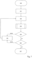
- Fig. 7 summarizes the various method steps explained above:
- the detection and evaluation of the current I may be used not only for configuring the device, but also for monitoring and/or continuously adjusting the series production.
- the offset may be determined, for example, for each glass pane, and for example one-half the offset may be used as a correction value for the next glass pane.
- the measures described here are usable in many ways to grind the edge of a glass pane, in particular automotive window glass and glass panes for monitors and/or displays. Any given edge profiles to be ground are conceivable: rectangular, beveled, C-shaped, rounded edge, stepped cut, etc.
- the detection and evaluation of a variable that is a function of the power consumption of the motor has the advantage, among others, that it is not absolutely necessary to provide additional sensors to determine the offset.
- the device may be configured in such a way that information concerning the detected values of the variable, for example the detected current, the determined offset, the calculated correction, and/or other parameters, is displayed on a monitor.
- values of the variable on only a portion of the grinding path represent sufficient measuring points to determine the offset having a maximum of three parameters.
- the method is also applicable for a device in which more than one grinding tool is used for the grinding, for example two or more grinding tools with motors that are offset relative to one another.
- Each grinding tool may optionally machine only a section of the edge.
- the correction values for each grinding tool may be determined, and an average correction value may then be set.
Landscapes
- Engineering & Computer Science (AREA)
- Mechanical Engineering (AREA)
- Chemical & Material Sciences (AREA)
- Ceramic Engineering (AREA)
- Inorganic Chemistry (AREA)
- Grinding And Polishing Of Tertiary Curved Surfaces And Surfaces With Complex Shapes (AREA)
- Surface Treatment Of Glass (AREA)
- Constituent Portions Of Griding Lathes, Driving, Sensing And Control (AREA)
Applications Claiming Priority (2)
| Application Number | Priority Date | Filing Date | Title |
|---|---|---|---|
| EP17200843 | 2017-11-09 | ||
| PCT/EP2018/079626 WO2019091820A1 (en) | 2017-11-09 | 2018-10-30 | Method for machining a glass pane |
Publications (3)
| Publication Number | Publication Date |
|---|---|
| EP3706952A1 EP3706952A1 (en) | 2020-09-16 |
| EP3706952C0 EP3706952C0 (en) | 2025-06-25 |
| EP3706952B1 true EP3706952B1 (en) | 2025-06-25 |
Family
ID=60301833
Family Applications (1)
| Application Number | Title | Priority Date | Filing Date |
|---|---|---|---|
| EP18795572.9A Active EP3706952B1 (en) | 2017-11-09 | 2018-10-30 | Method for machining a glass pane |
Country Status (8)
| Country | Link |
|---|---|
| US (1) | US20200346320A1 (pl) |
| EP (1) | EP3706952B1 (pl) |
| JP (1) | JP7273836B2 (pl) |
| CN (1) | CN111344110A (pl) |
| HU (1) | HUE073218T2 (pl) |
| PL (1) | PL3706952T3 (pl) |
| TW (1) | TWI811249B (pl) |
| WO (1) | WO2019091820A1 (pl) |
Families Citing this family (1)
| Publication number | Priority date | Publication date | Assignee | Title |
|---|---|---|---|---|
| JP7568609B2 (ja) * | 2019-02-25 | 2024-10-16 | ナブテスコオートモーティブ株式会社 | 空気供給システム、空気供給システムの制御方法、及び空気供給システムの制御プログラム |
Citations (2)
| Publication number | Priority date | Publication date | Assignee | Title |
|---|---|---|---|---|
| JP2003117815A (ja) * | 2001-10-16 | 2003-04-23 | Central Glass Co Ltd | ガラス板周縁部の研磨異常の検出方法 |
| EP1769885A1 (en) * | 2005-10-03 | 2007-04-04 | FOR.EL. BASE di VIANELLO FORTUNATO & C. S.n.c. | Automatic machine for arrissing and grinding the edges of glass sheets |
Family Cites Families (19)
| Publication number | Priority date | Publication date | Assignee | Title |
|---|---|---|---|---|
| US4525958A (en) * | 1981-11-19 | 1985-07-02 | Ppg Industries, Inc. | Method of controlling article speed during edge grinding |
| EP0255476A1 (de) | 1986-07-23 | 1988-02-03 | Bystronic Maschinen AG | Kanten-Schleifmaschine für Glasscheiben |
| JP3667483B2 (ja) * | 1997-02-10 | 2005-07-06 | 株式会社ニデック | レンズ研削加工装置 |
| ITMI990645U1 (it) * | 1999-10-25 | 2001-04-25 | Bovone Internat Holding S A | Dispositivo di avanzamento per macchine per la molatura di lastre di vetro |
| US7205166B2 (en) * | 2002-06-28 | 2007-04-17 | Lam Research Corporation | Method and apparatus of arrayed, clustered or coupled eddy current sensor configuration for measuring conductive film properties |
| ITTO20021010A1 (it) * | 2002-11-20 | 2004-05-21 | Biesse Spa | Metodo per il controllo della posizione operativa di una mola utilizzata su di una macchina per la lavorazione di bordi di lastre di vetro, marmo e simili materiali lapidei, e macchina per l'implementazione di tale metodo |
| US20060166608A1 (en) * | 2004-04-01 | 2006-07-27 | Chalmers Scott A | Spectral imaging of substrates |
| JP2007136632A (ja) * | 2005-11-21 | 2007-06-07 | Central Glass Co Ltd | ガラス板周縁部の未研磨異常の検出方法 |
| JP5270974B2 (ja) * | 2008-06-17 | 2013-08-21 | 中村留精密工業株式会社 | 基板端面の研磨装置及び研磨判定方法 |
| CN102427913B (zh) * | 2009-05-15 | 2014-01-15 | 旭硝子株式会社 | 玻璃端面磨削用磨具的加工位置设定方法 |
| JP5407693B2 (ja) * | 2009-09-17 | 2014-02-05 | 旭硝子株式会社 | ガラス基板の製造方法、研磨方法及び研磨装置、並びにガラス基板 |
| CN102069451A (zh) * | 2010-11-03 | 2011-05-25 | 广州遂联自动化设备有限公司 | 一种用在抛磨设备上的电流智能补偿控制方法 |
| US8747189B2 (en) * | 2011-04-26 | 2014-06-10 | Applied Materials, Inc. | Method of controlling polishing |
| CN102806513B (zh) * | 2012-08-14 | 2014-12-03 | 浙江大学 | 一种恒磨削量的抛光方法 |
| JP6128977B2 (ja) * | 2013-06-14 | 2017-05-17 | 中村留精密工業株式会社 | 板材の周縁加工装置並びに加工精度の計測及び補正方法 |
| US10474128B2 (en) * | 2015-11-16 | 2019-11-12 | Jtekt Corporation | Abnormality analysis system and analysis apparatus |
| CN105945729B (zh) * | 2016-04-27 | 2018-01-23 | 广东工业大学 | 一种金属回转件恒压力打磨控制装置及控制方法 |
| CN206169846U (zh) * | 2016-10-18 | 2017-05-17 | 上海发那科机器人有限公司 | 一种机器人伺服补偿抛光机构 |
| JP6784151B2 (ja) * | 2016-11-17 | 2020-11-11 | Agc株式会社 | 板状体の加工方法、および板状体の加工装置 |
-
2018
- 2018-10-09 TW TW107135593A patent/TWI811249B/zh active
- 2018-10-30 HU HUE18795572A patent/HUE073218T2/hu unknown
- 2018-10-30 WO PCT/EP2018/079626 patent/WO2019091820A1/en not_active Ceased
- 2018-10-30 EP EP18795572.9A patent/EP3706952B1/en active Active
- 2018-10-30 US US16/762,807 patent/US20200346320A1/en active Pending
- 2018-10-30 CN CN201880072044.1A patent/CN111344110A/zh active Pending
- 2018-10-30 PL PL18795572.9T patent/PL3706952T3/pl unknown
- 2018-10-30 JP JP2020544110A patent/JP7273836B2/ja active Active
Patent Citations (2)
| Publication number | Priority date | Publication date | Assignee | Title |
|---|---|---|---|---|
| JP2003117815A (ja) * | 2001-10-16 | 2003-04-23 | Central Glass Co Ltd | ガラス板周縁部の研磨異常の検出方法 |
| EP1769885A1 (en) * | 2005-10-03 | 2007-04-04 | FOR.EL. BASE di VIANELLO FORTUNATO & C. S.n.c. | Automatic machine for arrissing and grinding the edges of glass sheets |
Also Published As
| Publication number | Publication date |
|---|---|
| US20200346320A1 (en) | 2020-11-05 |
| TW201922412A (zh) | 2019-06-16 |
| WO2019091820A1 (en) | 2019-05-16 |
| CN111344110A (zh) | 2020-06-26 |
| EP3706952C0 (en) | 2025-06-25 |
| HUE073218T2 (hu) | 2026-01-28 |
| TWI811249B (zh) | 2023-08-11 |
| PL3706952T3 (pl) | 2025-11-17 |
| JP2021502267A (ja) | 2021-01-28 |
| JP7273836B2 (ja) | 2023-05-15 |
| EP3706952A1 (en) | 2020-09-16 |
Similar Documents
| Publication | Publication Date | Title |
|---|---|---|
| US8829383B2 (en) | Wire electric discharge machine and wire electric discharge machining method | |
| US11883973B2 (en) | Cutting apparatus and contact position specifying program | |
| EP2947528B1 (en) | Method of calculating stable spindle rotation number capable of suppressing chatter vibration, method of informing the same, method of controlling spindle rotation number, and method of editing nc program, and apparatus therefor | |
| US10189137B2 (en) | Tool shape measuring apparatus | |
| US5438178A (en) | Method of precision electric-discharge machining employing electrodes in the form of wires, and apparatus for carrying out the method | |
| KR20010007448A (ko) | 유리, 석재류 재료 등의 플레이트 에지를 기계 가공하는양면 자동 기계 | |
| JP2017037640A (ja) | 振動感知を用いる機械工具経路補正 | |
| JP2009036699A (ja) | 表面形状測定装置 | |
| CN108274303A (zh) | 自动确定齿轮切削机器中刀具几何尺寸的方法 | |
| JP5851436B2 (ja) | 加工装置及び加工方法 | |
| EP1707293A1 (en) | Method and device for measuring and adjusting the electrode for taper machining on an electrical discharge machine | |
| EP3706952B1 (en) | Method for machining a glass pane | |
| KR20170007149A (ko) | 와이어 방전 가공기 | |
| EP2646187A1 (en) | Centering method for optical elements | |
| CN115070137A (zh) | 平面齿轮倒角装置和平面齿轮倒角加工方法 | |
| CN114442249A (zh) | 一种贴装工件角度调整方法和系统 | |
| CN109164755B (zh) | 控制工具对工件定长切割的加工方法、切割装置和机床 | |
| CN113478034B (zh) | 一种线切割加工方法 | |
| EP2484491A1 (en) | Method of phasing threaded grinding stone, as well as gear grinding machine | |
| KR20200050062A (ko) | 밀링장치의 절삭력을 추정하는 방법 | |
| EP2730361B1 (en) | Wire electric discharge machine having peak current compensation function | |
| EP2402831B1 (en) | Processing device and processing method | |
| JP2012111009A (ja) | 工作機械の切削加工評価装置及び方法 | |
| EP2741156A2 (en) | Machining method | |
| EP3537245A1 (en) | Edging method and apparatus |
Legal Events
| Date | Code | Title | Description |
|---|---|---|---|
| STAA | Information on the status of an ep patent application or granted ep patent |
Free format text: STATUS: UNKNOWN |
|
| STAA | Information on the status of an ep patent application or granted ep patent |
Free format text: STATUS: THE INTERNATIONAL PUBLICATION HAS BEEN MADE |
|
| PUAI | Public reference made under article 153(3) epc to a published international application that has entered the european phase |
Free format text: ORIGINAL CODE: 0009012 |
|
| STAA | Information on the status of an ep patent application or granted ep patent |
Free format text: STATUS: REQUEST FOR EXAMINATION WAS MADE |
|
| 17P | Request for examination filed |
Effective date: 20200423 |
|
| AK | Designated contracting states |
Kind code of ref document: A1 Designated state(s): AL AT BE BG CH CY CZ DE DK EE ES FI FR GB GR HR HU IE IS IT LI LT LU LV MC MK MT NL NO PL PT RO RS SE SI SK SM TR |
|
| AX | Request for extension of the european patent |
Extension state: BA ME |
|
| DAV | Request for validation of the european patent (deleted) | ||
| DAX | Request for extension of the european patent (deleted) | ||
| RAP3 | Party data changed (applicant data changed or rights of an application transferred) |
Owner name: GLASTON SWITZERLAND AG |
|
| TPAC | Observations filed by third parties |
Free format text: ORIGINAL CODE: EPIDOSNTIPA |
|
| STAA | Information on the status of an ep patent application or granted ep patent |
Free format text: STATUS: EXAMINATION IS IN PROGRESS |
|
| 17Q | First examination report despatched |
Effective date: 20231016 |
|
| GRAP | Despatch of communication of intention to grant a patent |
Free format text: ORIGINAL CODE: EPIDOSNIGR1 |
|
| STAA | Information on the status of an ep patent application or granted ep patent |
Free format text: STATUS: GRANT OF PATENT IS INTENDED |
|
| INTG | Intention to grant announced |
Effective date: 20250206 |
|
| GRAS | Grant fee paid |
Free format text: ORIGINAL CODE: EPIDOSNIGR3 |
|
| GRAA | (expected) grant |
Free format text: ORIGINAL CODE: 0009210 |
|
| STAA | Information on the status of an ep patent application or granted ep patent |
Free format text: STATUS: THE PATENT HAS BEEN GRANTED |
|
| AK | Designated contracting states |
Kind code of ref document: B1 Designated state(s): AL AT BE BG CH CY CZ DE DK EE ES FI FR GB GR HR HU IE IS IT LI LT LU LV MC MK MT NL NO PL PT RO RS SE SI SK SM TR |
|
| REG | Reference to a national code |
Ref country code: GB Ref legal event code: FG4D |
|
| REG | Reference to a national code |
Ref country code: CH Ref legal event code: EP |
|
| REG | Reference to a national code |
Ref country code: CH Ref legal event code: EP |
|
| REG | Reference to a national code |
Ref country code: IE Ref legal event code: FG4D |
|
| U01 | Request for unitary effect filed |
Effective date: 20250625 |
|
| U07 | Unitary effect registered |
Designated state(s): AT BE BG DE DK EE FI FR IT LT LU LV MT NL PT RO SE SI Effective date: 20250701 |
|
| PG25 | Lapsed in a contracting state [announced via postgrant information from national office to epo] |
Ref country code: GR Free format text: LAPSE BECAUSE OF FAILURE TO SUBMIT A TRANSLATION OF THE DESCRIPTION OR TO PAY THE FEE WITHIN THE PRESCRIBED TIME-LIMIT Effective date: 20250926 Ref country code: NO Free format text: LAPSE BECAUSE OF FAILURE TO SUBMIT A TRANSLATION OF THE DESCRIPTION OR TO PAY THE FEE WITHIN THE PRESCRIBED TIME-LIMIT Effective date: 20250925 |
|
| PG25 | Lapsed in a contracting state [announced via postgrant information from national office to epo] |
Ref country code: HR Free format text: LAPSE BECAUSE OF FAILURE TO SUBMIT A TRANSLATION OF THE DESCRIPTION OR TO PAY THE FEE WITHIN THE PRESCRIBED TIME-LIMIT Effective date: 20250625 |
|
| PG25 | Lapsed in a contracting state [announced via postgrant information from national office to epo] |
Ref country code: RS Free format text: LAPSE BECAUSE OF FAILURE TO SUBMIT A TRANSLATION OF THE DESCRIPTION OR TO PAY THE FEE WITHIN THE PRESCRIBED TIME-LIMIT Effective date: 20250925 |
|
| REG | Reference to a national code |
Ref country code: CH Ref legal event code: U11 Free format text: ST27 STATUS EVENT CODE: U-0-0-U10-U11 (AS PROVIDED BY THE NATIONAL OFFICE) Effective date: 20251101 |
|
| U20 | Renewal fee for the european patent with unitary effect paid |
Year of fee payment: 8 Effective date: 20251028 |
|
| PGFP | Annual fee paid to national office [announced via postgrant information from national office to epo] |
Ref country code: HU Payment date: 20251103 Year of fee payment: 8 |
|
| PG25 | Lapsed in a contracting state [announced via postgrant information from national office to epo] |
Ref country code: IS Free format text: LAPSE BECAUSE OF FAILURE TO SUBMIT A TRANSLATION OF THE DESCRIPTION OR TO PAY THE FEE WITHIN THE PRESCRIBED TIME-LIMIT Effective date: 20251025 |
|
| PG25 | Lapsed in a contracting state [announced via postgrant information from national office to epo] |
Ref country code: SM Free format text: LAPSE BECAUSE OF FAILURE TO SUBMIT A TRANSLATION OF THE DESCRIPTION OR TO PAY THE FEE WITHIN THE PRESCRIBED TIME-LIMIT Effective date: 20250625 |
|
| PGFP | Annual fee paid to national office [announced via postgrant information from national office to epo] |
Ref country code: CH Payment date: 20251101 Year of fee payment: 8 |
|
| PGFP | Annual fee paid to national office [announced via postgrant information from national office to epo] |
Ref country code: CZ Payment date: 20251021 Year of fee payment: 8 |
|
| PGFP | Annual fee paid to national office [announced via postgrant information from national office to epo] |
Ref country code: PL Payment date: 20250929 Year of fee payment: 8 |
|
| PG25 | Lapsed in a contracting state [announced via postgrant information from national office to epo] |
Ref country code: SK Free format text: LAPSE BECAUSE OF FAILURE TO SUBMIT A TRANSLATION OF THE DESCRIPTION OR TO PAY THE FEE WITHIN THE PRESCRIBED TIME-LIMIT Effective date: 20250625 |
|
| REG | Reference to a national code |
Ref country code: HU Ref legal event code: AG4A Ref document number: E073218 Country of ref document: HU |
|
| PG25 | Lapsed in a contracting state [announced via postgrant information from national office to epo] |
Ref country code: ES Free format text: LAPSE BECAUSE OF FAILURE TO SUBMIT A TRANSLATION OF THE DESCRIPTION OR TO PAY THE FEE WITHIN THE PRESCRIBED TIME-LIMIT Effective date: 20250625 |