EP3706660B1 - Zahnkrone mit einer hochgradig zurückhaltenden beschichtung und verfahren zu ihrer herstellung - Google Patents
Zahnkrone mit einer hochgradig zurückhaltenden beschichtung und verfahren zu ihrer herstellung Download PDFInfo
- Publication number
- EP3706660B1 EP3706660B1 EP18799603.8A EP18799603A EP3706660B1 EP 3706660 B1 EP3706660 B1 EP 3706660B1 EP 18799603 A EP18799603 A EP 18799603A EP 3706660 B1 EP3706660 B1 EP 3706660B1
- Authority
- EP
- European Patent Office
- Prior art keywords
- dental crown
- metal
- coating
- layer
- retention layer
- Prior art date
- Legal status (The legal status is an assumption and is not a legal conclusion. Google has not performed a legal analysis and makes no representation as to the accuracy of the status listed.)
- Active
Links
Images


Classifications
-
- A—HUMAN NECESSITIES
- A61—MEDICAL OR VETERINARY SCIENCE; HYGIENE
- A61C—DENTISTRY; APPARATUS OR METHODS FOR ORAL OR DENTAL HYGIENE
- A61C5/00—Filling or capping teeth
- A61C5/70—Tooth crowns; Making thereof
- A61C5/77—Methods or devices for making crowns
-
- A—HUMAN NECESSITIES
- A61—MEDICAL OR VETERINARY SCIENCE; HYGIENE
- A61C—DENTISTRY; APPARATUS OR METHODS FOR ORAL OR DENTAL HYGIENE
- A61C5/00—Filling or capping teeth
- A61C5/70—Tooth crowns; Making thereof
-
- A—HUMAN NECESSITIES
- A61—MEDICAL OR VETERINARY SCIENCE; HYGIENE
- A61K—PREPARATIONS FOR MEDICAL, DENTAL OR TOILETRY PURPOSES
- A61K6/00—Preparations for dentistry
- A61K6/80—Preparations for artificial teeth, for filling teeth or for capping teeth
- A61K6/84—Preparations for artificial teeth, for filling teeth or for capping teeth comprising metals or alloys
-
- A—HUMAN NECESSITIES
- A61—MEDICAL OR VETERINARY SCIENCE; HYGIENE
- A61K—PREPARATIONS FOR MEDICAL, DENTAL OR TOILETRY PURPOSES
- A61K6/00—Preparations for dentistry
- A61K6/80—Preparations for artificial teeth, for filling teeth or for capping teeth
- A61K6/884—Preparations for artificial teeth, for filling teeth or for capping teeth comprising natural or synthetic resins
- A61K6/887—Compounds obtained by reactions only involving carbon-to-carbon unsaturated bonds
-
- A—HUMAN NECESSITIES
- A61—MEDICAL OR VETERINARY SCIENCE; HYGIENE
- A61C—DENTISTRY; APPARATUS OR METHODS FOR ORAL OR DENTAL HYGIENE
- A61C13/00—Dental prostheses; Making same
- A61C13/0003—Making bridge-work, inlays, implants or the like
- A61C13/0006—Production methods
- A61C13/0021—Production methods using stamping techniques
-
- A—HUMAN NECESSITIES
- A61—MEDICAL OR VETERINARY SCIENCE; HYGIENE
- A61C—DENTISTRY; APPARATUS OR METHODS FOR ORAL OR DENTAL HYGIENE
- A61C13/00—Dental prostheses; Making same
- A61C13/0003—Making bridge-work, inlays, implants or the like
- A61C13/0022—Blanks or green, unfinished dental restoration parts
-
- B—PERFORMING OPERATIONS; TRANSPORTING
- B21—MECHANICAL METAL-WORKING WITHOUT ESSENTIALLY REMOVING MATERIAL; PUNCHING METAL
- B21D—WORKING OR PROCESSING OF SHEET METAL OR METAL TUBES, RODS OR PROFILES WITHOUT ESSENTIALLY REMOVING MATERIAL; PUNCHING METAL
- B21D22/00—Shaping without cutting, by stamping, spinning, or deep-drawing
- B21D22/20—Deep-drawing
- B21D22/26—Deep-drawing for making peculiarly, e.g. irregularly, shaped articles
-
- B—PERFORMING OPERATIONS; TRANSPORTING
- B23—MACHINE TOOLS; METAL-WORKING NOT OTHERWISE PROVIDED FOR
- B23K—SOLDERING OR UNSOLDERING; WELDING; CLADDING OR PLATING BY SOLDERING OR WELDING; CUTTING BY APPLYING HEAT LOCALLY, e.g. FLAME CUTTING; WORKING BY LASER BEAM
- B23K20/00—Non-electric welding by applying impact or other pressure, with or without the application of heat, e.g. cladding or plating
- B23K20/02—Non-electric welding by applying impact or other pressure, with or without the application of heat, e.g. cladding or plating by means of a press ; Diffusion bonding
-
- Y—GENERAL TAGGING OF NEW TECHNOLOGICAL DEVELOPMENTS; GENERAL TAGGING OF CROSS-SECTIONAL TECHNOLOGIES SPANNING OVER SEVERAL SECTIONS OF THE IPC; TECHNICAL SUBJECTS COVERED BY FORMER USPC CROSS-REFERENCE ART COLLECTIONS [XRACs] AND DIGESTS
- Y10—TECHNICAL SUBJECTS COVERED BY FORMER USPC
- Y10T—TECHNICAL SUBJECTS COVERED BY FORMER US CLASSIFICATION
- Y10T29/00—Metal working
- Y10T29/49—Method of mechanical manufacture
- Y10T29/49567—Dental appliance making
-
- Y—GENERAL TAGGING OF NEW TECHNOLOGICAL DEVELOPMENTS; GENERAL TAGGING OF CROSS-SECTIONAL TECHNOLOGIES SPANNING OVER SEVERAL SECTIONS OF THE IPC; TECHNICAL SUBJECTS COVERED BY FORMER USPC CROSS-REFERENCE ART COLLECTIONS [XRACs] AND DIGESTS
- Y10—TECHNICAL SUBJECTS COVERED BY FORMER USPC
- Y10T—TECHNICAL SUBJECTS COVERED BY FORMER US CLASSIFICATION
- Y10T29/00—Metal working
- Y10T29/49—Method of mechanical manufacture
- Y10T29/49826—Assembling or joining
- Y10T29/49888—Subsequently coating
Definitions
- Preformed stainless-steel crowns are still the preferred choice for whole or parital replacements of teeth. They are a very durable and reliable restoration for a tooth in need of complete coverage. However, stainless-steel crowns have an unattractive appearance. Thus, there is a need for stainless-steel dental crowns that have a more natural look with preferably a more natural look with a tooth-like appearance.
- Various dental crowns and methods of making dental crowns are disclosed, for example in: U.S. Pat. No. 4,068,379 ; U.S. Pat. No. 6,663,390 ; U.S. Pat. No. 6,106,295 ; U.S. Pat. No. 7,008,229 ; U.S. Pat. No.
- DE 3600977 A1 describes a method of producing crowns, bridges or denture parts jacketed wholly or partially with porcelain or plastic having underlays as support. However, it is always desirable to create better solutions for creating long lasting dental crowns.
- the invention is set out in the appended set of claims.
- the invention pertains to a dental crown as defined in claims 1 and 9, and to a method for forming a dental crown as defined in claim 14.
- the dental crown could include a metal shell shaped to cover a portion of a tooth of a patient; a coating retention metal layer diffusion bonded to the metal shell, wherein an interface between the coating retention layer and the metal shell comprises a plurality of interstitial regions; and a composition on the coating retention layer and within the plurality of the interstitial regions to bond the coating composition to the metal shell.
- the dental crown could include a continuous, nonporous metal shell shaped to cover a portion of a tooth of a patient; a coating retention metal layer of elongated metal strands diffusion bonded to the metal shell, wherein there are apertures between the elongated metal strands, wherein the apertures between the elongated metal strands comprise 10 to 60 percent of the area of the coating retention layer, and wherein an interface between the coating retention layer and the metal shell comprises a plurality of interstitial regions; and a polymeric composition on the coating retention layer and within a plurality of the interstitial regions to bond the coating composition to the metal shell.
- Some aspects of the present disclosure provide a method of forming a dental crown.
- the method includes diffusion bonding a metal base layer to a coating retention layer to form a dental crown blank, wherein the coating retention layer comprises a plurality of apertures wherein an interface between the metal base layer and the coating retention layer comprises a plurality of interstitial regions; coating a composition on the coating retention layer and within the plurality of the interstitial regions to bond the coating composition to the metal base layer; and forming the dental crown blank into a dental crown shaped to cover at least a portion of a tooth of a patient.
- Some other aspects of the present disclosure provide a method of forming a dental crown.
- This method which is not according to the invention and present for illustrative purposes only may include bonding a continuous, nonporous metal base layer to a coating retention layer to form a dental crown blank, wherein the coating retention layer comprises a plurality of apertures wherein an interface between the metal base layer and the coating retention layer comprises a plurality of interstitial regions, wherein the plurality of apertures between the elongated metal strands comprise 10 to 70 percent of the area of the coating retention layer; and coating a composition on the coating retention layer and within the plurality of the interstitial regions to bond the coating composition to the metal base layer; and forming the dental crown blank into a dental crown shaped to cover at least a portion of a tooth of a patient.
- FIGs 3-5 illustrate exemplary examples of the esthetic dental crown of the present invention.
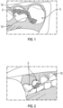
- Dental crown 10 is being shown in Figure 1 as it is being placed in the mouth to cover a prepared tooth 12.
- the prepared tooth 12 is shown as having its surface ground away sufficiently for the placement of the crown 10 thereon.
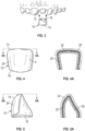
- Figure 4 and 4A are convenient for illustrating the various layers that are used to create a laminate used in the dental crown 10.
- the dental crown has an occlusal surface 14 and an open end 16 opposite the occlusal surface 14 for receiving the prepared tooth 12.
- the dental crown is shaped to resemble the original tooth it replaces, and the open end 16 is for placement over the prepared tooth 12. It is sized to fit comfortably over the portion of the tooth 12 on which the dental procedure is being performed.
- the crown is trimmed so that the bottom edge of the crown meets the gum line in a comfortable manner approximating the placement of the tooth when the crown 10 is applied.
- the crowns 10 are manufactured in various size and shapes to fit different types of teeth.
- the crown 10 is malleable so it can be crimped around the base of the tooth and shaped on the occlusal surface to provide a comfortable bite with the opposing tooth. However, the coating 24 is retained on the crown 10 during this crimping and shaping steps. Proper tooth preparation includes removing all caries and proper shaping the remaining natural tooth to receive the dental crown 10.
- the dental crown 10 has a metal layer or foil 20, shown as a metal shell.
- the metal for the shell 20 is preferably stainless steel, but also could be aluminum, tin, silver, gold and any alloys thereof.
- the metal layer is preferably a continuous layer and nonporous. This is to prevent the coating material from seeping into the interior of the crown, which might interfere with the crown preparation and placement.
- the dental crown 10 has a coating retention layer 22.
- the retention layer 22 is preferably stainless steel, but also could be aluminum, tin, silver, gold and any alloys thereof.
- the retention layer keeps the coating 24 highly retained on the metal shell 20, even after long periods of use. Due to the mechanical structure of the retention layer, the coating 24 is strongly adhered to the metal shell 20, as described in more detail below relative to Figures 9 through 10 .
- the esthetic coating layer 24 does not delaminate or sheer off. Likewise, as the dental crown 10 receives various occlusal forces from the opposing teeth or food, the esthetic coating layer 24 does not delaminate or shear off from the crown 10.
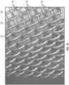
- the coating retention layer 22 is made from a mesh of intermingled, elongated strands of metal.
- the metal strands 26 may be woven into a variety of patterns. Examples of some patterns are illustrated in Figures 18A-D . Alternatively, the metal strands 26 may be arranged in a nonwoven mesh. Regardless, the open spaces between adjacent metal strands 26 create apertures 30 within the coating retention layer 22.
- Figure 4 shows a molar crown 10.
- Figure 5 shows an eyetooth crown 10.
- the present invention is applicable to both anterior and posterior crowns as well.
- the present invention provides a dental crown 10 that may be suitable for all types of crowns that could be used by a prospective dental patient, which are long lasting.
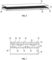
- Figure 6 is convenient for illustrating the various layers used for making the laminate in the dental crown 10 of the present invention during the diffusion bonding portion of the method.
- a metal layer or foil 20 is brought into contact with a coating retention layer 22.
- a separator sheet 38 is brought into contact with the coating retention layer 22.
- a stack 80 of these three layers is then heated in a furnace while being forced together in a press, as illustrated in Figure 8 and discussed more below, to bond the metal layer 20 and coating retention layer 22. Thereafter, the separator sheet 38 is removed, and thus a laminate for a dental blank is created.
- Figure 7 shows a magnified view of the metal layer 20 and coating retention layer 22 prior to this diffusion bonding process and Figure 9 shows a magnified view after the diffusion bonding process.
- interstitial regions 32 when the metal layer 20 is adjacent to the coating retention layer 22, the interface between the two creates a plurality of interstitial regions 32. These open spaces provide regions for conveniently receiving the polymeric composition 24, when it is applied over the coating retention layer 22, described in more detail below.
- the interstitial regions 32 underlie at least a portion of the metal strands 26, but ideally underlie the majority of the metal strands 26.
- FIG. 8 One exemplary embodiment for diffusion bonding the metal layer 20 to the coating retention layer 22 is shown in Figure 8 .
- the stack 80 of metal layer 20, retention layer 22, and separator sheet 38 put into a hot press furnace having two opposing plates 50, 52.
- the stack 80 is heated by the furnace and the plates 50 and 52 apply pressure.
- the time and temperature is picked to allow the metal layers 20, 22 to diffuse into each other at the points of contact, but to still maintain the interstitial regions 32.
- the furnace may be heated within a range of 300 to 900°C.
- Other metals, temperatures, pressures, and times may be selected by known by one skilled in the art.
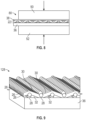
- Figure 9 shows a magnified picture of the retention layer 22 and the metal base layer 20 after the diffusion bonding step. As illustrated, the portion of the metal strands 26 adjacent to the metal base layer 20 have melted with the metal base layer to create bonded areas 28. Adjacent the top surface of the metal base layer 20 and underlying the metal strands 26 are the interstitial regions 32.
- Figure 10 illustrates a magnified picture of the layers after the bonding process described above.
- Each of the metal strands 26 in the coating retention layer 22 are bonded to the base metal layer 20 in areas 28. Between the metal strands 26 are apertures 30.
- the coating retention layer 22 is selected so that the plurality of apertures 30 contribute 10 to 60 percent of the total area of the coating retention layer 22.
- the coating retention layer 22 is selected so that the plurality of apertures 30 contribute 30 to 60 percent of the total area of the coating retention layer 22.
- a coating retention layer 22 with an 80 mesh with a 4-mil (94 micrometer diameter) wire gauge provides 46% area of apertures or open area.
- the number of apertures 30 may be optimized to allow enough open area for the composition 24 to sufficiently bond to the metal layer 20 and to flow into the interstitial regions 32 for additional bonding areas and around the metal strands 26.
- the number of apertures 30 may also be optimized to provide enough metal strands 26 to sufficiently bond with the metal layer 20.
- the gauge of the metal strands 26 may also be optimized to sufficiently bond with the metal layer 20
- the dental blank is created, it is then formed into a dental crown by deep drawing the blank with a series of forming dies.
- One exemplary process for deep drawing is according to process DIN 8585-3.
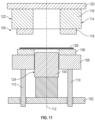
- a deep-drawing die illustrated schematically in Figures 11 to 14 , which is convenient for illustrating the method step for converting the dental blank into a dental crown 10.
- the deep-drawing die set 100 includes a base plate 102, a drawing punch 104 arranged stationarily on the upper side of the base plate 102, and a sheet-metal holder 106 which surrounds the drawing punch 104 in a ring shape and is arranged on a supporting plate 108 which likewise surrounds the drawing punch 104 in a ring shape and is borne by spindle sleeves 110 which can be moved vertically be means of a hydraulic moving device (not illustrated) so that the supporting plate 108 can be moved with the sheet metal holder 106 arranged thereon along the vertical direction drawing 112.
- the deep-drawing die set 100 also includes a drawing member 114 which is arranged above the drawing punch 104 and the sheet metal holder 106 and comprises, for its part, a ring-shaped drawing ring support 116 and a drawing ring 118 held on its underside.
- the drawing ring support 116 is held at its upper side on a holding plate 120 which can be moved by means of a hydraulic moving device (not illustrated) along the direction of drawing 112 relative to the drawing punch 104 and the sheet metal holder 106.
- the drawing member 114 forms the first deep-drawing die part 122 of the deep-drawing die set 100; the drawing punch 104 forms the second deep-drawing die part 124 of the deep-drawing die set 100.
- a first deep-drawing process is carried out as follows with the deep-drawing die set 100 described above.
- the drawing member 114 and the sheet metal holder 106 are displaced into their respective upper starting positions by means of the respective hydraulic moving devices (not illustrated).
- the essentially flat upper side of the sheet metal holder 106 In the upper starting position of the sheet metal holder 106, the essentially flat upper side of the sheet metal holder 106, the essentially flat upper side of the sheet metal holder 106 is arranged above the upper side of the drawing punch 104.
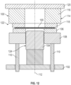
- the dental blank 126 from which the drawn part is intended to be produced, is inserted into the deep-drawing die set 100 such that the edge of the blank 126 rests on the sheet metal 106, as illustrated in Figure 12 .
- the deep-drawing die set 100 is closed in that the drawing member is displaced by means of the hydraulic moving device (not illustrated) downwards out of its upper starting position to such an extent along the direction of drawing 112 until the underside of the drawing ring 118 on the upper side of the blank 126 and the edge of the blank 126 is clamped between the drawing ring 118 and the sheet metal holder 106, as illustrated in Figure 13 .
- the blank 126 is formed into a drawn part 128 in that the spindle sleeves 110 with the supporting plate 108 arranged thereon and the sheet metal holder 106 as well as the drawing member 114 are moved downwards by means of the hydraulic moving device (not illustrated) along the direction of drawing 112 relative to the drawing punch 104 by the drawing depth, wherein the blank 126 held securely at its edge between the drawing ring 118 and the sheet metal holder 106 fits closely along the outer contours of the drawing ring 118 and the drawing punch 104, as illustrated in Figure 14 .
- the spindle sleeves 110 are moved back into their upper starting position with the supporting plate 108 arranged thereon and the sheet metal holder 106 and the deep-drawing die set 100 is opened in that the drawing member 114 is moved further along the direction of drawing 112 upwards into its upper starting position, as illustrated in Figure 15 .
- the drawn part 128 formed during the first deep-drawing process is accessible from outside the deep-drawing die set 100 and can be removed from it. There are often successive deep drawing die sets that continue to form the drawn part 128 to the final desired dimensions.
- the drawn part 128 may then be converted into a dental crown 10 of the present invention by trimming the excess flange around the portion that contacted the sheet metal holder 106.
- FIG. 15 illustrates a cross section of the finished dental blank 130.
- the polymeric composition is applied over the top of the retention layer 22, into the interstitial regions 32, around the metal strands 26 and in contact with the metal base layer 20 to form a coating 24.
- the coating 24 may be hardened to mechanically bond the coating to the metal base layer 20, especially via retention layer 22.
- the hardened composition in the interstitial regions 32 adjacent the metal strands 26 and metal layer 20 assist in adhering the coating to the base layer.
- the coating After hardening, the coating is mechanically bonded to the metal layer 20 by the coating being locked into place within interstitial regions 32 and around the metal strands 26.
- the coating, mesh, and base combination are still flexible enough to be shaped and crimped easily by a dentist.
- the retention layer 22 also provides strength and flexibility.
- both layers may be sandblasted or primed prior to the coating process.
- One way to apply the esthetic layer 24 is to electrostatically apply powder to the metal retention layer 22 and base layer 20.
- suitable powder is ALESTA epoxy-polyester hybrid, which is commercially available from Axalta Coating Systems based in Houston, Texas.
- hardenable compositions of the present disclosure are typically hardenable due to the presence of a polymerizable component.
- the term “hardenable” refers to a material that can be cured or solidified, e.g., by heating to remove solvent, heating to cause polymerization, chemical crosslinking, radiation-induced polymerization or crosslinking, or the like.
- compositions can be hardened (e.g., polymerized by heat, conventional photopolymerization and/or chemical polymerization techniques) after it has been applied to the surface of a dental article.
- the compositions are photopolymerizable, i.e., the compositions contain a photoinitiator system that upon irradiation with actinic radiation initiates the polymerization (or hardening) of the composition.
- the compositions are chemically hardenable, i.e., the compositions contain a chemical initiator (i.e., initiator system) that can polymerize, cure, or otherwise harden the composition without dependence on irradiation with actinic radiation.
- a chemical initiator i.e., initiator system
- Such chemically hardenable compositions are sometimes referred to as "self-cure" compositions.
- compositions are thermally polymerizable, i.e., the compositions contain a thermal initiator system that upon heating or other application of thermal energy initiates the polymerization (or hardening) of the composition.
- (meth)acrylate is a shorthand reference to acrylate, methacrylate, or combinations thereof
- (meth)acrylic is a shorthand reference to acrylic, methacrylic, or combinations thereof.
- (meth)acrylate-functional compounds are compounds that include, among other things, a (meth)acrylate moiety.
- the polymerizable component typically comprises one or more ethylenically unsaturated compounds, with or without acid functionality.
- useful ethylenically unsaturated compounds include acrylic acid esters, methacrylic acid esters, hydroxy-functional acrylic acid esters, hydroxy-functional methacrylic acid esters, and combinations thereof.
- the polymerizable component may comprise one or more ethylenically unsaturated compounds, with or without acid functionality that is phosphorylated, such as a phosphorylated methacrylate.
- the polymeric composition comprises a polymerizable component is selected from the group consisting of phenoxyethyl methacrylate, urethane dimethacrylate, polyethylene glycol methacrylate, polypropylene glycol methacrylate, triethyleneglycol dimethacrylate, the diglycidyl methacrylate of bisphenol A, and combinations thereof.
- the composition is a polymer or copolymer chosen from epoxy, polyester, and hybrids thereof.
- the composition may be a thermoplastic polymer. If so, the thermoplastic polymer could be from polyetheretherketone (PEEK), polyaryletherketone (PAEK), polyphenolsulfones, polyethersulfones, polyacrylamide, PTFE or combinations thereof.
- the coating composition is retained on the metal shell with a minimum bond strength of at least 5 MPa. This is to provide a dental crown that will endure the various forces applied to it while the patient is chewing.
- the metal shell has a thickness in the range of 50 to 250 micrometers. In a more preferred embodiment, the metal shell 20 has a thickness in the range of 50 to 150 micrometers. In another preferred embodiment, the coating retention layer 22 has a thickness in the range of 50 to 125 micrometers. Overall, the dental crown 10 has a thickness in the range of 50 to 700 micrometers. Such preferred thickness ranges provide flexibility and durability.
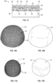
- Figures 16A and 17A show examples of dental crowns 128 after the deep drawing process step described above, but prior to the coating process step.
- Figures 16B and 17B show examples of dental crowns after both the deep drawing process and coating process steps.
- the top or occlusal surface of the dental crown 10 will include grooves, indentations and or dimples (not shown), similar to normal dentition.
- the occlusal surface is shaped into the metal base layer 20 as part of the deep drawing process described in Figures 11-14 , prior to the bonding and coating processes described above.
- Figures 18A-D illustrate several examples of exemplary coating retention layer 22 having different wire mesh weave styles.
- Figure 18A illustrates a plain weave style.
- the mesh layer 22 shown in Figures 16A and 7A have a plain weave style.
- Figure 18B illustrates a twill square weave style.
- Figure 18C illustrates a reverse plain Dutch weave style.
- Figure 18D illustrates a plain Dutch weave style.
- the coating retention layer 22 in Figures 18A and 18B has apertures 30 that comprise between 40 and 50 percent of the area of the coating retention layers.
- the coating retention layer 22 in Figures 18C and 18D has apertures 30 that comprise between 1 and 10 percent of the area of the coating retention layers.
- Embodiments 19 to 36, 54 to 66 and 70 are not according to the invention and are present for illustrative purposes only.
- Embodiment 1 is a dental crown comprising: a metal shell shaped to cover a portion of a tooth of a patient; a coating retention metal layer diffusion bonded to the metal shell, wherein an interface between the coating retention layer and the metal shell comprises a plurality of interstitial regions; and a composition on the coating retention layer and within the plurality of the interstitial regions to bond the coating composition to the metal shell.
- Embodiment 2 is the dental crown of embodiment 1, wherein the coating retention layer comprises an interwoven mesh, the mesh comprising a plurality of elongated metal strands, and the interstitial regions underlie at least a portion of the strands.
- Embodiment 3 is the dental crown of embodiment 2, wherein a plurality of apertures between the plurality of elongated metal strands comprise 10 to 60 percent of the area of the coating retention layer.
- Embodiment 4 is the dental crown of embodiment 3, wherein the open spaces between the elongated metal strands comprise 30 to 40 percent of the area of the coating retention layer.
- Embodiment 5 is the dental crown of Embodiments 1, 3 and 4, wherein the coating retention layer comprises a nonwoven mesh of elongated metal strands, and the interstitial regions underlie at least a portion of the strands.
- Embodiment 6 is the dental crown of Embodiments 1-5, wherein the coating composition is hardened or cured by heating to remove solvent, heating to cause polymerization, chemical crosslinking, radiation-induced polymerization or crosslinking.
- Embodiment 7 is the dental crown of Embodiments 1-6, wherein the composition comprises a polymer or copolymer chosen from epoxy, polyester, and hybrids thereof.
- Embodiment 8 is the dental crown of claims 1-7, wherein the composition comprises a thermoplastic polymer.
- Embodiment 9 is the dental crown of Embodiment 8, wherein the composition comprises a thermoplastic polymer chosen from polyetheretherketone (PEEK), polyaryletherketone (PAEK), polyphenolsulfones, polyethersulfones, polyacrylamide, PTFE and combinations thereof.
- a thermoplastic polymer chosen from polyetheretherketone (PEEK), polyaryletherketone (PAEK), polyphenolsulfones, polyethersulfones, polyacrylamide, PTFE and combinations thereof.
- Embodiment 10 is the dental crown of Embodiments 1-9, wherein the metal shell and/or the coating retention layer comprise stainless steel alloys.
- Embodiment 11 is the dental crown of Embodiments 1-10, wherein the coating composition is retained on the metal shell with a minimum bond strength of 5 MPa.
- Embodiments 12 is the dental crown of Embodiments 1-11, wherein the composition comprises a polymerizable component selected from the group consisting of phenoxyethyl methacrylate, urethane dimethacrylate, polyethylene glycol methacrylate, polypropylene glycol methacrylate, triethyleneglycol dimethacrylate, the diglycidyl methacrylate of bisphenol A, and combinations thereof.
- a polymerizable component selected from the group consisting of phenoxyethyl methacrylate, urethane dimethacrylate, polyethylene glycol methacrylate, polypropylene glycol methacrylate, triethyleneglycol dimethacrylate, the diglycidyl methacrylate of bisphenol A, and combinations thereof.
- Embodiment 13 is the dental crown of Embodiments 1-12, wherein the metal shell has a thickness in the range of 50 to 250 micrometers.
- Embodiment 14 is the dental crown of Embodiments 1-13, wherein the metal shell has a thickness in the range of 50 to 150 micrometers.
- Embodiment 15 is the dental crown of Embodiments 1-14, wherein the coating retention layer has a thickness in the range of 50 to 125 micrometers.
- Embodiment 16 is the dental crown of Embodiments 1-15, wherein the dental crown has a thickness in the range of 50 to 700 micrometers.
- Embodiment 17 is the dental crown of Embodiments 1-16, wherein the metal shell is a continuous, nonporous layer of metal.
- Embodiment 18 is the dental crown of claims 1-17, wherein the composition comprises powder.
- Embodiment 19 is a dental crown comprising: a continuous, nonporous metal shell shaped to cover a portion of a tooth of a patient; a coating retention metal layer of elongated metal strands bonded to the metal shell, wherein there are apertures between the elongated metal strands, wherein the apertures between the elongated metal strands comprise 10 to 60 percent of the area of the coating retention layer, and wherein an interface between the coating retention layer and the metal shell comprises a plurality of interstitial regions; and a polymeric composition on the coating retention layer and within a plurality of the interstitial regions to bond the coating composition to the metal shell.
- Embodiment 20 is the dental crown of Embodiment 19, wherein the plurality of apertures between the elongated metal strands comprise 30 to 40 percent of the area of the coating retention layer.
- Embodiment 21 is the dental crown of Embodiments 19-20, wherein the coating retention layer comprises an interwoven mesh, the mesh comprising a plurality of elongated metal strands, and the interstitial regions underlie at least a portion of the strands.
- Embodiment 22 is the dental crown of Embodiments 19-20, wherein the coating retention layer comprises a nonwoven mesh of elongate metal strands, and the interstitial regions underlie at least a portion of the strands.
- Embodiment 23 is the dental crown of Embodiments 19-22, wherein the composition is hardened or cured by heating to remove solvent, heating to cause polymerization, chemical crosslinking, radiation-induced polymerization or crosslinking.
- Embodiment 24 is the dental crown of Embodiments 19-23 wherein the composition is photocurable.
- Embodiment 25 is the dental crown of Embodiments 19-24, wherein the composition comprises a polymer or copolymer chosen from epoxy, polyester, and hybrids thereof.
- Embodiment 26 is the dental crown of Embodiments 19-25, wherein the coating composition comprises a thermoplastic polymer.
- Embodiment 27 is the dental crown of Embodiment 26, wherein the coating comprises a thermoplastic polymer chosen from polyetheretherketone (PEEK), polyaryletherketone (PAEK), polyphenolsulfones, polyethersulfones, polyacrylamide, PTFE and combinations thereof.
- a thermoplastic polymer chosen from polyetheretherketone (PEEK), polyaryletherketone (PAEK), polyphenolsulfones, polyethersulfones, polyacrylamide, PTFE and combinations thereof.
- Embodiment 28 is the dental crown of Embodiments 19-27, wherein the metal shell and/or the coating retention layer comprise stainless steel alloys.
- Embodiment 29 is the dental crown of Embodiments 19-28, wherein the composition is retained on the metal shell with a minimum bond strength of 5 MPa.
- Embodiment 30 is the dental crown of Embodiments 19-29, wherein the polymeric composition comprises a polymerizable component is selected from the group consisting of phenoxyethyl methacrylate, urethane dimethacrylate, polyethylene glycol methacrylate, polypropylene glycol methacrylate, triethyleneglycol dimethacrylate, the diglycidyl methacrylate of bisphenol A, and combinations thereof.
- a polymerizable component is selected from the group consisting of phenoxyethyl methacrylate, urethane dimethacrylate, polyethylene glycol methacrylate, polypropylene glycol methacrylate, triethyleneglycol dimethacrylate, the diglycidyl methacrylate of bisphenol A, and combinations thereof.
- Embodiment 31 is the dental crown of Embodiments 19-30, wherein the metal shell has a thickness in the range of 50 to 250 micrometers.
- Embodiment 32 is the dental crown of Embodiments 19-31, wherein the metal shell has a thickness in the range of 50 to 150 micrometers.
- Embodiment 33 is the dental crown of Embodiments 19-32, wherein the coating retention layer has a thickness in the range of 50 to 125 micrometers.
- Embodiment 34 is the dental crown of Embodiments 19-33, wherein the dental crown has a thickness in the range of 50 to 700 micrometers.
- Embodiment 35 is the dental crown of Embodiments 19-34, wherein the metal shell is a continuous, nonporous layer of metal.
- Embodiment 36 is the dental crown of Embodiments 19-35, wherein the composition comprises powder.
- Embodiment 37 is a method of forming a dental crown, comprising: diffusion bonding a metal base layer to a coating retention layer to form a dental crown blank, wherein the coating retention layer comprises a plurality of apertures wherein an interface between the metal base layer and the coating retention layer comprises a plurality of interstitial regions; coating a composition on the coating retention layer and within the plurality of the interstitial regions to bond the coating composition to the metal base layer; and forming the dental crown blank into a dental crown shaped to cover at least a portion of a tooth of a patient.
- Embodiment 38 is the method of Embodiment 37, wherein the forming step comprises pressing the blank through a die.
- Embodiment 39 is the method of Embodiments 37-38, wherein the forming step comprises deep drawing the blank according to DIN 8584-3.
- Embodiment 40 is the method of Embodiments 37-39, wherein the coating retention layer comprises a mesh of interwoven elongate metal strands, and wherein the plurality of interstitial regions is between the metal strands and the base layer.
- Embodiment 41 is the method of Embodiments 37-40, further comprising hardening the coating composition to form a coating overlying at least a portion of the coating retention layer.
- Embodiments 42 is the method of Embodiments 37-41, wherein the coating step includes electrostatically powder coating the retention layer and heating.
- Embodiment 43 is the method of Embodiments 37-42, wherein the composition is hardened or cured by heating to remove solvent, heating to cause polymerization, chemical crosslinking, radiation-induced polymerization or crosslinking.
- Embodiment 44 is the method of Embodiments 37-43, wherein the thermoplastic composition comprises a polymer or copolymer chosen from epoxy, polyester, and hybrids thereof.
- Embodiment 45 is the method of Embodiments 37-44, wherein the coating comprises a thermoplastic polymer.
- Embodiment 46 is the method of Embodiments 37-45, wherein composition comprises a thermoplastic polymer, and wherein the thermoplastic polymer is chosen from polyetheretherketone (PEEK), polyaryletherketone (PAEK), polyphenolsulfones, polyethersulfones, polyacrylamide, PTFE, and combinations thereof.
- the thermoplastic polymer is chosen from polyetheretherketone (PEEK), polyaryletherketone (PAEK), polyphenolsulfones, polyethersulfones, polyacrylamide, PTFE, and combinations thereof.
- Embodiment 47 is the method of Embodiments 37-46, wherein the composition comprises a polymerizable component is selected from the group consisting of phenoxyethyl methacrylate, urethane dimethacrylate, polyethylene glycol methacrylate, polypropylene glycol methacrylate, triethyleneglycol dimethacrylate, the diglycidyl methacrylate of bisphenol A, and combinations thereof.
- a polymerizable component is selected from the group consisting of phenoxyethyl methacrylate, urethane dimethacrylate, polyethylene glycol methacrylate, polypropylene glycol methacrylate, triethyleneglycol dimethacrylate, the diglycidyl methacrylate of bisphenol A, and combinations thereof.
- Embodiment 48 is the method of Embodiments 37-47, wherein the plurality of apertures between the elongated metal strands comprise 10 to 70 percent of the area of the coating retention layer.
- Embodiment 49 is the dental crown of Embodiment 48, wherein the plurality of apertures between the elongated metal strands comprise 30 to 40 percent of the area of the coating retention layer.
- Embodiment 50 is the method of Embodiments 37-49, wherein at least one of the metal base layer and the coating retention layer comprise a stainless-steel alloy, or wherein both the metal base layer and the coating retention layer comprise stainless steel alloys.
- Embodiment 51 is the method of Embodiments 37-50, wherein the coating retention layer comprises a nonwoven mesh of elongate metal strands, and the interstitial regions underlie at least a portion of the strands.
- Embodiment 52 is the method of Embodiments 37-51, wherein the coating composition is retained on the metal shell with at least a bond strength of 5 MPa.
- Embodiment 53 is the method of Embodiments 37-51, further comprising: selecting the dental crown of claim 1 to cover a tooth portion of a patient; customizing the dental crown for the patient; and attaching the dental crown to the tooth of the patient.
- Embodiment 54 is a method of forming a dental crown, comprising: bonding a continuous, nonporous metal base layer to a coating retention layer to form a dental crown blank, wherein the coating retention layer comprises a plurality of apertures wherein an interface between the metal base layer and the coating retention layer comprises a plurality of interstitial regions, wherein the plurality of apertures between the elongated metal strands comprise 10 to 70 percent of the area of the coating retention layer; and coating a composition on the coating retention layer and within the plurality of the interstitial regions to bond the coating composition to the metal base layer; and forming the dental crown blank into a dental crown shaped to cover at least a portion of a tooth of a patient.
- Embodiment 55 is the method of Embodiment 54, wherein the plurality of apertures comprises 30 to 40 percent of the area of the coating retention layer.
- Embodiment 56 is the method of Embodiments 54-55, wherein the forming step comprises pressing the blank through a die.
- Embodiment 57 is the method of Embodiments 54-56, wherein the forming step comprises deep drawing the blank according to DIN 8584-3.
- Embodiment 58 is the method of Embodiments 54-57, wherein the coating retention layer comprises a mesh of interwoven elongate metal strands, wherein the plurality of apertures is between the plurality of metal strands, and wherein the plurality of interstitial regions between the metal strands and the base layer.
- Embodiment 59 is the method of Embodiments 54-58, further comprising hardening the composition on the coating retention layer.
- Embodiment 60 is the method of Embodiments 54-59, wherein the composition is hardened or cured by heating to remove solvent, heating to cause polymerization, chemical crosslinking, radiation-induced polymerization or crosslinking.
- Embodiment 61 is the dental crown of Embodiments 54-60, wherein the composition comprises a polymerizable component is selected from the group consisting of phenoxyethyl methacrylate, urethane dimethacrylate, polyethylene glycol methacrylate, polypropylene glycol methacrylate, triethyleneglycol dimethacrylate, the diglycidyl methacrylate of bisphenol A, and combinations thereof.
- a polymerizable component is selected from the group consisting of phenoxyethyl methacrylate, urethane dimethacrylate, polyethylene glycol methacrylate, polypropylene glycol methacrylate, triethyleneglycol dimethacrylate, the diglycidyl methacrylate of bisphenol A, and combinations thereof.
- Embodiment 62 is the method of Embodiments 54-61, wherein the composition comprises a polymer or copolymer chosen from epoxy, polyester, and hybrids thereof.
- Embodiment 63 is the method of Embodiments 54-62, wherein the coating composition comprises a thermoplastic polymer, and wherein the thermoplastic polymer is chosen from polyetheretherketone (PEEK), polyaryletherketone (PAEK), polyphenolsulfones, polyethersulfones, polyacrylamide, PTFE, and combinations thereof.
- the thermoplastic polymer is chosen from polyetheretherketone (PEEK), polyaryletherketone (PAEK), polyphenolsulfones, polyethersulfones, polyacrylamide, PTFE, and combinations thereof.
- Embodiment 64 is the method of Embodiments 54-63, wherein at least one of the metal base layer and the coating retention layer comprise a stainless-steel alloy, or wherein both the metal base layer and the coating retention layer comprise stainless steel alloys.
- Embodiment 65 is the method of Embodiments 54-64, wherein the coating retention layer comprises a nonwoven mesh of elongate metal strands, and the interstitial regions underlie at least a portion of the strands.
- Embodiment 66 is the method of Embodiments 54-65, wherein the coating composition is retained on the metal shell with a minimum bond strength of 5 MPa.
- Embodiment 67 is the method of Embodiments 54-66, wherein the bonding step includes diffusion bonding the metal base layer to the coating retention layer.
- Embodiment 68 is the method of Embodiment 67, wherein diffusion bonding comprises heat and pressure.
- Embodiment 69 is the method of Embodiments 54-68, wherein the coating step includes electrostatically powder coating the retention layer and heating.
- Embodiment 70 is the method of claim 54-69, further comprising: selecting the dental crown of Embodiment 19 to cover a tooth portion of a patient; customizing the dental crown for the patient; and attaching the dental crown to the tooth of the patient.
- a 2.5 cm x 2.5 cm square piece of the diffusion bonded stainless steel foil/mesh laminate was coated with 3M FILTEK Supreme Ultra Flowable Restorative and light cured using a 400-500 nm visible curing light. The cured restorative composite material adhered well to the substrate.
- Dental crown structures were simulated in the form of simple hemispherical caps, such as those shown in Figures 16A and 17A .
- a 2.5 cm x 2.5 cm square piece of the diffusion bonded stainless steel foil/mesh laminate was formed into a hemispherical cap using a simple punch die to simulate a deep-drawing process.
- the deep-drawing process is used in manufacturing to create commercially available preformed stainless-steel crowns from 304-L SS foils.
- These formed caps were dry-powder coated with an electrostatic spraying process and using the following powder: RAL 9001 Cream - Polyester TGIC Weather Resistant Powder Coating.
- the caps were first washed with cleaning solution and rinsed with water prior to electrostatic coating. After the application of the powder coating, the caps were baked at 400°F (204°C) for 10 minutes. The final coating was approximately 125 micrometers thick.
- the mesh side of a 2.5 cm x 2.5 cm square piece of the diffusion bonded stainless steel foil/mesh laminate was cleaned with acetone.
- the disc mold was lined with a gelatin capsule through the hole of the PTFE mold and then cut flush with a razor to the top and bottom surface of the mold, thus making a gelatin sleeve to line the mold.
- the gelatin sleeve will dissolve when exposed to water and this will facilitate easy removal later of the mold without disrupting the cured composite material.
- the disc-shaped mold with gelatin sleeve was clamped onto the mesh side of the foil/mesh laminate the metal piece.
- the final test object of Example 3 was a 2.5 cm square piece of the SS foil/mesh laminate with a circular button/disc (5 millimeter in diameter and 2-millimeter-thick) of composite material bonded to the mesh side of the SS foil/mesh laminate.
- Comparative Example 1 was prepared in the same manner as Example 3 except that the foil side of the foil/mesh laminate was cleaned with acetone and the FILTEK Supreme Ultra Flowable Restorative composite material was applied and cured to the foil side of a stainless-steel foil/mesh laminate sheet.
- Comparative Example 2 was prepared in the same manner as Comparative Example 1, except that the foil side of the foil/mesh laminate was first sandblasted with 3M ROCATEC- PLUS sandblasting material and then cleaned with acetone. Finally, FILTEK Supreme Ultra Flowable Restorative composite material was applied and cured to the sandblasted prepared foil side of a stainless-steel foil/mesh laminate sheet.
- Comparative Example 3 was prepared in the same manner as Comparative Example 2, except that after the foil side of the foil/mesh laminate was sandblasted and then cleaned with acetone and dried, and then further a primer layer of 3M RelyX Ceramic Primer was applied for 20 seconds to the sandblasted, cleaned foil side of the laminate, followed by air drying of the primer. Finally, FILTEK Supreme Ultra Flowable Restorative composite material was applied and cured to the sandblasted and primer prepared foil side of a stainless-steel foil/mesh laminate sheet.
- Shear bond strength of the composite material to the metal substrate was measured for Example 3, and Comparative Examples 1-3 according to the following procedure. Each example was prepared and tested with 5 replicates. Prior to the shear bond strength testing the PTFE disc mold was removed. The shear bond strength of a cured test examples was evaluated by clamping one end of the metal laminate in the jaws of an INSTRON testing machine (Instron 5944) with the metal surface oriented parallel to the direction of push. A notched-edge fixture (hemispherical in shape, designed to fit and engage one half of the composite button/disc) was placed around the cured composite material button adjacent to the metal surface.
- INSTRON testing machine Instron 5944
- the notched-edge fixture was clamped in the travelling jaw of the INSTRON apparatus and pushed at a crosshead speed of 1 millimeter per minute, thereby placing the adhesive bond in shear stress, with a pushing force.
- the force in kilograms (kg) at which the bond failed was recorded, and this number was converted to a force per unit area (units of kg/cm 2 or MPa) using the known surface area of the button.
- each surface was observed to determine the mode failure where it was characterized as "adhesive" when there was no remnant of the cured composite material left on the metal surface, or "cohesive" when there was remnant of the cured composite material left on the metal surface.
- Each reported value of adhesion represents the average of 5 replicates.
Landscapes
- Health & Medical Sciences (AREA)
- Oral & Maxillofacial Surgery (AREA)
- Epidemiology (AREA)
- Life Sciences & Earth Sciences (AREA)
- Animal Behavior & Ethology (AREA)
- General Health & Medical Sciences (AREA)
- Public Health (AREA)
- Veterinary Medicine (AREA)
- Dentistry (AREA)
- Plastic & Reconstructive Surgery (AREA)
- Dental Prosthetics (AREA)
- Dental Tools And Instruments Or Auxiliary Dental Instruments (AREA)
Claims (14)
- Zahnkrone (10), umfassend:eine Metallhülle (20), die so geformt ist, dass sie einen Teil eines Zahns (12) eines Patienten bedeckt;eine Beschichtungshaltemetallschicht (22), die an die Metallhülle diffusionsgebunden ist, wobei eine Schnittstelle zwischen der Beschichtungshaltemetallschicht und der Metallhülle eine Vielzahl von Zwischenräumen (32) umfasst; undeine Zusammensetzung (24) auf der Beschichtungshaltemetallschicht und innerhalb der Vielzahl von Zwischenräumen, um die Zusammensetzung mit der Metallhülle zu verbinden.
- Zahnkrone nach Anspruch 1, wobei die Beschichtungshalteschicht ein verwobenes Netz umfasst, wobei das Netz eine Vielzahl von länglichen Metallsträngen umfasst und die Zwischenräumen mindestens unter einem Teil der Stränge liegen.
- Zahnkrone nach Anspruch 1, wobei die Beschichtungshalteschicht ein Vliesgeflecht aus länglichen Metallsträngen umfasst, und die Zwischenräume mindestens unter einem Teil der Stränge liegen.
- Zahnkrone nach Anspruch 1, wobei die Zusammensetzung durch Erhitzen zum Entfernen des Lösungsmittels, durch Erhitzen zum Herbeiführen einer Polymerisation, durch chemische Vernetzung, durch strahlungsinduzierte Polymerisation oder Vernetzung härtbar oder aushärtbar ist.
- Zahnkrone nach Anspruch 1, wobei die Zusammensetzung ein Polymer oder Copolymer umfasst, ausgewählt aus Epoxid, Polyester und Hybriden davon.
- Zahnkrone nach Anspruch 1, wobei die Zusammensetzung ein thermoplastisches Polymer umfasst, ausgewählt aus Polyetheretherketon (PEEK), Polyaryletherketon (PAEK), Polyphenolsulfonen, Polyethersulfonen, Polyacrylamid, PTFE und Kombinationen davon.
- Zahnkrone nach Anspruch 1, wobei die Zusammensetzung eine polymerisierbare Komponente umfasst, die aus der Gruppe ausgewählt ist, die aus Phenoxyethylmethacrylat, Urethandimethacrylat, Polyethylenglykolmethacrylat, Polypropylenglykolmethacrylat, Triethylenglykoldimethacrylat, dem Diglycidylmethacrylat von Bisphenol A und Kombinationen davon besteht.
- Zahnkrone nach Anspruch 1, wobei die Zusammensetzung Pulver umfasst.
- Zahnkrone (10), umfassend:eine durchgehende, nicht-poröse Metallhülle (20), die so geformt ist, dass sie einen Teil eines Zahns (12) eines Patienten bedeckt;eine Beschichtungshaltemetallschicht (22) aus länglichen Metallsträngen (26), die an die Metallhülle diffusionsgebunden sind, wobei sich zwischen den länglichen Metallsträngen Öffnungen (30) befinden, wobei die Öffnungen zwischen den länglichen Metallsträngen 10 bis 60 Prozent der Fläche der Beschichtungshalteschicht ausmachen, und wobei eine Schnittstelle zwischen der Beschichtungshalteschicht und der Metallhülle eine Vielzahl von Zwischenräumen umfasst; und eine Polymerzusammensetzung (24) auf der Beschichtungshalteschicht und innerhalb einer Vielzahl der Zwischenräume, um die Polymerzusammensetzung an die Metallhülle zu binden, wobei die Zusammensetzung ein thermoplastisches Polymer umfasst, ausgewählt aus Polyetheretherketon (PEEK), Polyaryletherketon (PAEK), Polyphenolsulfonen, Polyethersulfonen, Polyacrylamid, PTFE und Kombinationen davon.
- Zahnkrone nach Anspruch 9, wobei die Zusammensetzung ein Polymer oder Copolymer umfasst, ausgewählt aus Epoxid, Polyester und Hybriden davon.
- Zahnkrone nach Anspruch 9, wobei die Polymerzusammensetzung ein Polyetheretherketon (PEEK) umfasst.
- Zahnkrone nach Anspruch 9, wobei die Polymerzusammensetzung eine polymerisierbare Komponente umfasst, die aus der Gruppe ausgewählt ist, die aus Phenoxyethylmethacrylat, Urethandimethacrylat, Polyethylenglykolmethacrylat, Polypropylenglykolmethacrylat, Triethylenglykoldimethacrylat, dem Diglycidylmethacrylat von Bisphenol A und Kombinationen davon besteht.
- Zahnkrone nach Anspruch 9, wobei die Zusammensetzung Pulver umfasst.
- Verfahren zum Formen einer Zahnkrone, umfassend:Diffusionsbinden einer Metallbasisschicht an eine Beschichtungshalteschicht, um einen Zahnkronenrohling zu bilden, wobei die Beschichtungshalteschicht eine Vielzahl von Öffnungen umfasst, wobei eine Schnittstelle zwischen der Metallbasisschicht und der Beschichtungshalteschicht eine Vielzahl von Zwischenräumen umfasst;elektrostatisches Pulverbeschichten einer Zusammensetzung auf der Beschichtungshalteschicht und innerhalb der Vielzahl von Zwischenräumen und Erhitzen, um die Zusammensetzung mit der Metallbasisschicht zu verbinden; undFormen des Zahnkronenrohlings zu einer Zahnkrone, die so geformt ist, dass sie mindestens einen Teil eines Zahns eines Patienten bedeckt.
Applications Claiming Priority (2)
| Application Number | Priority Date | Filing Date | Title |
|---|---|---|---|
| US201762582100P | 2017-11-06 | 2017-11-06 | |
| PCT/IB2018/058590 WO2019087126A1 (en) | 2017-11-06 | 2018-11-01 | Dental crown having a highly retentive coating and methods for making the same |
Publications (2)
| Publication Number | Publication Date |
|---|---|
| EP3706660A1 EP3706660A1 (de) | 2020-09-16 |
| EP3706660B1 true EP3706660B1 (de) | 2025-04-23 |
Family
ID=64172535
Family Applications (1)
| Application Number | Title | Priority Date | Filing Date |
|---|---|---|---|
| EP18799603.8A Active EP3706660B1 (de) | 2017-11-06 | 2018-11-01 | Zahnkrone mit einer hochgradig zurückhaltenden beschichtung und verfahren zu ihrer herstellung |
Country Status (4)
| Country | Link |
|---|---|
| US (2) | US20210401543A1 (de) |
| EP (1) | EP3706660B1 (de) |
| CN (1) | CN111315313B (de) |
| WO (1) | WO2019087126A1 (de) |
Families Citing this family (5)
| Publication number | Priority date | Publication date | Assignee | Title |
|---|---|---|---|---|
| CN113164227B (zh) * | 2018-12-07 | 2022-09-27 | 3M创新有限公司 | 具有三维打印的高保持层的牙科牙冠及其制造方法 |
| WO2021064759A1 (en) * | 2019-09-30 | 2021-04-08 | Luigi Salvatore Sposato | A three-layer dental prosthesis |
| IT201900017585A1 (it) * | 2019-09-30 | 2021-03-30 | Luigi Salvatore Sposato | Nuova protesi dentaria in peek e resina composita a tre strati. |
| IT202000022735A1 (it) * | 2020-09-25 | 2022-03-25 | Luigi Salvatore Sposato | Protesi dentaria a tre strati |
| JP2026013212A (ja) * | 2024-07-16 | 2026-01-28 | 株式会社神戸製鋼所 | 絞り加工品の製造方法 |
Citations (5)
| Publication number | Priority date | Publication date | Assignee | Title |
|---|---|---|---|---|
| US4364731A (en) * | 1981-01-29 | 1982-12-21 | Board Of Regents, The University Of Texas System | Methods for producing adhesive bonds between substrate and polymer employing an intermediate oxide layer |
| DE3600977A1 (de) * | 1986-01-15 | 1986-08-07 | Karl-Heinz Dr. Mauren Schmidt | Verfahren zur herstellung von mit porzellan oder kunststoff ganz oder teilweise ummantelten kronen, bruecken oder prothesenteilen mit metallunterlagen |
| US20100081110A1 (en) * | 2006-12-28 | 2010-04-01 | Woodwelding Ag | Method for affixing an artificial element to a surface of dentine, enamel, bone, or a corresponding substitute material, and set for carrying out the method |
| US20130130203A1 (en) * | 2010-08-11 | 2013-05-23 | 3M Innovative Properties Company | Polymer coated dental articles and method of making the same |
| US20130137064A1 (en) * | 2010-08-11 | 2013-05-30 | 3M Innovative Properties Company | Coated dental crowns and method of making the same |
Family Cites Families (56)
| Publication number | Priority date | Publication date | Assignee | Title |
|---|---|---|---|---|
| US3969480A (en) * | 1971-06-02 | 1976-07-13 | Gould Inc. | Nickel base nox reducing catalytic structure |
| US4068379A (en) * | 1977-03-18 | 1978-01-17 | Ormco Corporation | Orthodontic appliance with porous tooth-abutting face |
| US4273580A (en) * | 1979-04-04 | 1981-06-16 | Itzhak Shoher | Reinforced jacket crown and method of construction |
| US4398887A (en) * | 1980-02-29 | 1983-08-16 | Balde John W | Dental crown assembly |
| EP0051704B1 (de) | 1980-11-10 | 1985-07-24 | Melvyn Peter Butler | Verfahren zur Herstellung einer Zahnkrone |
| US4392829A (en) * | 1981-03-31 | 1983-07-12 | Asami Tanaka | Metal-porcelain dental restoration and method of making |
| DE3409865A1 (de) | 1984-03-17 | 1985-09-26 | Fa. E. & H. Renfert, 7700 Singen | Hilfsmittel zum herstellen eines rasters aus gussmetall sowie verwendung des hilfsmittels und verfahren dazu |
| SU1237197A1 (ru) * | 1984-06-28 | 1986-06-15 | Пермская Стоматологическая Поликлиника N2 | Зубна коронка |
| EP0169552B1 (de) * | 1984-07-26 | 1989-07-12 | Renfert GmbH & Co. | Zahnersatzteil |
| DE3435918A1 (de) * | 1984-09-29 | 1986-04-10 | Karl-Heinz Dr.Dr. 6050 Offenbach Klähn | Zahnkrone aus metall |
| US4698021A (en) * | 1985-01-11 | 1987-10-06 | Itzhak Shoher | Metal foil for forming a dental coping and crown |
| US4722689A (en) * | 1985-12-20 | 1988-02-02 | Corbett Jack A | Coated temporary dental crowns |
| US5186626A (en) * | 1987-05-13 | 1993-02-16 | Asami Tanaka Dental Enterprises | Metal-porcelain dental bridges |
| US4834656A (en) * | 1987-06-26 | 1989-05-30 | Loudon Merle E | Adjustable composite dental crown and associated procedure |
| SE470346B (sv) * | 1992-06-23 | 1994-01-31 | Sandvik Ab | Metod för framställning av keramiska artificiella tandrestaurationer |
| CN1083342A (zh) * | 1992-09-01 | 1994-03-09 | 冯玉球 | 有关牙冠的改进 |
| US5346397A (en) * | 1993-06-15 | 1994-09-13 | Braiman Kenneth S | Process for making ceramic dental crowns |
| US5722826A (en) * | 1996-02-21 | 1998-03-03 | American Orthodontics Corporation | Bonding pad |
| US6129261A (en) * | 1996-09-26 | 2000-10-10 | The Boeing Company | Diffusion bonding of metals |
| CN1163093A (zh) | 1997-02-04 | 1997-10-29 | 赵培英 | 一种修复牙缺失用网状骨架 |
| EP0943296A1 (de) * | 1998-03-17 | 1999-09-22 | Eidgenössische Technische Hochschule Zürich | Zahnkronen und/oder Zahnbrücken |
| AUPQ210199A0 (en) * | 1999-08-09 | 1999-09-02 | Fung, John | Improved dental crown |
| US6106295A (en) * | 1999-08-09 | 2000-08-22 | Gsf Trust | High density polyethylene veneered crowns for children |
| US20040109783A1 (en) * | 2000-01-10 | 2004-06-10 | Arun Prasad | Method for the manufacture of dental restorations |
| US6722883B2 (en) * | 2000-11-13 | 2004-04-20 | G & H Technologies Llc | Protective coating for abrasive dental tools and burs |
| US6663387B2 (en) | 2001-05-14 | 2003-12-16 | Centerpulse Dental Inc. | Near net tooth shaped ceramic crown and method |
| NL1018887C2 (nl) * | 2001-09-04 | 2003-03-05 | Malte De Moll | Werkwijze voor het vervaardigen van een gebitsprothese. |
| GB0205868D0 (en) * | 2002-03-13 | 2002-04-24 | Univ Nottingham | Polymer composite with internally distributed deposition matter |
| US7008229B2 (en) | 2002-04-12 | 2006-03-07 | 3M Innovative Properties Company | Stainless steel dental crowns with a polyester/epoxy coating |
| EP1534212A1 (de) * | 2002-06-20 | 2005-06-01 | Doxa Aktiebolag | System fur ein zahnfullmaterial oder implantationsmaterial und pulverformiges material, hydratationsflussigkeit, implantationsmaterial und verbindungsverfahren |
| US6955540B2 (en) * | 2002-08-23 | 2005-10-18 | Woodwelding Ag | Preparation for being fastened on a natural tooth part or tooth and corresponding fastening method |
| US20050040551A1 (en) * | 2003-08-19 | 2005-02-24 | Biegler Robert M. | Hardenable dental article and method of manufacturing the same |
| DE102005023105B4 (de) * | 2005-05-13 | 2012-09-06 | Sirona Dental Systems Gmbh | Verfahren zur Herstellung eines Zahnersatzteils und ein derart hergestelltes Zahnersatzteil |
| DE102005055526A1 (de) * | 2005-11-22 | 2007-06-06 | BEGO Bremer Goldschlägerei Wilh. Herbst GmbH & Co. KG | Verfahren und System zum Erzeugen einer dentalen Prothese |
| WO2007098485A2 (en) * | 2006-02-21 | 2007-08-30 | Nusmile, Ltd. | Prefabricated dental crowns |
| US20090286205A1 (en) * | 2006-02-21 | 2009-11-19 | Johnson Jason K | Prefabricated Dental Crowns |
| WO2007097747A1 (en) * | 2006-02-21 | 2007-08-30 | The Ex One Corporation | Metal-bearing dental restorations by three-dimensional printing |
| ATE442168T1 (de) * | 2006-05-17 | 2009-09-15 | Debiotech Sa | Anisotrope nanoporíse beschichtungen für medizinische implantate |
| CN101547661A (zh) * | 2006-09-13 | 2009-09-30 | 3M创新有限公司 | 预成形的延展性多层牙科制品 |
| US10507083B2 (en) * | 2006-12-28 | 2019-12-17 | Woodwelding Ag | Affixing an artificial element to a surface of dentine, enamel, bone, or a corresponding substitute material |
| US20110230973A1 (en) * | 2007-10-10 | 2011-09-22 | Zimmer, Inc. | Method for bonding a tantalum structure to a cobalt-alloy substrate |
| FR2939636B1 (fr) * | 2008-12-16 | 2012-01-27 | Coste Bruno Clunet | Preforme de renforcement en forme de grille, et materiau composite a fibres preimpregnees pour prothese dentaire, et procede de fabrication de la grille |
| US20100203480A1 (en) * | 2009-02-06 | 2010-08-12 | Dean Schweitzer | Dental crown shell and method of use |
| EP2482757B1 (de) * | 2009-09-30 | 2019-06-26 | 3M Innovative Properties Company | Systeme und verfahren zur herstellung geschichteter zahnanwendungen |
| US9370404B2 (en) * | 2010-08-11 | 2016-06-21 | Bhaskar V. Velamakanni | Aesthetic and abrasion resistant coated dental articles and methods of making the same |
| US9044292B2 (en) | 2010-08-11 | 2015-06-02 | 3M Innovative Properties Company | Dental articles including a ceramic and microparticle coating and method of making the same |
| EP2614810B1 (de) * | 2012-01-16 | 2017-12-06 | Kerr Corporation | Auf Thermoplast basierte Polymerhaftzusammensetzungen und Vorrichtungen für ihre Verwendung in Zahnanwendungen |
| CN202605038U (zh) * | 2012-02-03 | 2012-12-19 | 北京爱威白商贸有限公司 | 一种牙冠 |
| US8936848B2 (en) * | 2012-02-23 | 2015-01-20 | B&D Dental Corp | Non-pre-colored multi-layer zirconia dental blank that has a gradual change in translucency through a thickness after sintering |
| CN203493761U (zh) * | 2013-09-26 | 2014-03-26 | 南京市口腔医院 | 牙龈美学愈合基台 |
| CN104720904A (zh) * | 2015-04-07 | 2015-06-24 | 西安新定远精密齿研有限公司 | 颈部肩台陶瓷替代金属颈缘肩台的烤瓷牙及其制作方法 |
| EP3302588A4 (de) * | 2015-05-29 | 2019-01-23 | Launchpad Medical, LLC | Zusammensetzungen und verfahren zur haftung auf oberflächen |
| CA3024099A1 (en) * | 2016-05-19 | 2017-11-23 | Figaro Crowns Inc. | Fiberglass dental crowns |
| CN205913413U (zh) * | 2016-06-16 | 2017-02-01 | 广州瑞通生物科技有限公司 | 一种定制化埋伏牙牵引矫治装置 |
| CN206183400U (zh) * | 2016-07-16 | 2017-05-24 | 上海正雅齿科科技有限公司 | 双层牙套 |
| CN106308951A (zh) * | 2016-08-11 | 2017-01-11 | 广州锦冠桥实业有限公司 | 一种美学修复瓷及其堆塑方法 |
-
2018
- 2018-11-01 EP EP18799603.8A patent/EP3706660B1/de active Active
- 2018-11-01 WO PCT/IB2018/058590 patent/WO2019087126A1/en not_active Ceased
- 2018-11-01 CN CN201880071754.2A patent/CN111315313B/zh active Active
- 2018-11-01 US US16/761,325 patent/US20210401543A1/en not_active Abandoned
-
2023
- 2023-10-23 US US18/492,179 patent/US12336878B2/en active Active
Patent Citations (5)
| Publication number | Priority date | Publication date | Assignee | Title |
|---|---|---|---|---|
| US4364731A (en) * | 1981-01-29 | 1982-12-21 | Board Of Regents, The University Of Texas System | Methods for producing adhesive bonds between substrate and polymer employing an intermediate oxide layer |
| DE3600977A1 (de) * | 1986-01-15 | 1986-08-07 | Karl-Heinz Dr. Mauren Schmidt | Verfahren zur herstellung von mit porzellan oder kunststoff ganz oder teilweise ummantelten kronen, bruecken oder prothesenteilen mit metallunterlagen |
| US20100081110A1 (en) * | 2006-12-28 | 2010-04-01 | Woodwelding Ag | Method for affixing an artificial element to a surface of dentine, enamel, bone, or a corresponding substitute material, and set for carrying out the method |
| US20130130203A1 (en) * | 2010-08-11 | 2013-05-23 | 3M Innovative Properties Company | Polymer coated dental articles and method of making the same |
| US20130137064A1 (en) * | 2010-08-11 | 2013-05-30 | 3M Innovative Properties Company | Coated dental crowns and method of making the same |
Non-Patent Citations (1)
| Title |
|---|
| RUSNALDY: "DIFFUSION BONDING : AN ADVANCED OF MATERIAL PROCESS", ROTASI, vol. 3, no. 1, January 2001 (2001-01-01), pages 23 - 27, XP093150970, Retrieved from the Internet <URL:https://ejournal.undip.ac.id/index.php/rotasi/article/view/2487/2199> [retrieved on 20240412] * |
Also Published As
| Publication number | Publication date |
|---|---|
| WO2019087126A1 (en) | 2019-05-09 |
| US20240050196A1 (en) | 2024-02-15 |
| US12336878B2 (en) | 2025-06-24 |
| US20210401543A1 (en) | 2021-12-30 |
| CN111315313B (zh) | 2022-05-03 |
| EP3706660A1 (de) | 2020-09-16 |
| CN111315313A (zh) | 2020-06-19 |
Similar Documents
| Publication | Publication Date | Title |
|---|---|---|
| US12336878B2 (en) | Dental crown having a highly retentive coating and method for making the same | |
| JP4745232B2 (ja) | 硬化性歯科物品およびその製造方法 | |
| US4820157A (en) | Dental bridge | |
| US4479527A (en) | Method for facilitating the manufacture of a bondable metallic surface | |
| EP0707833A1 (de) | Verfahren zur Verstärkung der Bindungskraft einer orthodontischen Einrichtung an einem Zahn | |
| WO2010053588A2 (en) | Methods for indirect bonding of orthodontic appliances | |
| JP6865157B2 (ja) | 硬化性歯科用物品を使用する方法 | |
| DE212007000066U1 (de) | Kieferorthopädische Elemente und andere medizinische Vorrichtungen mit einem fluorierten Polymer | |
| US11957535B1 (en) | Preparation tray for improved etching and bonding of a tooth surface prior to the placement of a tooth attachment or a bracket | |
| JP7719990B2 (ja) | 硬化性歯科用物品を使用する方法 | |
| US4650550A (en) | Manufacture and repair of dental appliances | |
| US4531566A (en) | Method and article for facilitating the manufacture of a bondable metallic surface | |
| US20070111152A1 (en) | Pre-cemented orthodontic appliances | |
| EP3890648B1 (de) | Zahnkrone mit einer dreidimensionalen gedruckten hochretentiven schicht und verfahren zu ihrer herstellung | |
| JP2024503594A (ja) | 接着可能な歯科矯正アセンブリ及び接着方法 | |
| CA1254776A (en) | Manufacture and repair of dental appliances | |
| Uchida et al. | Evaluation of bonding methods on shear bond strength between cobalt-chromium and titanium alloys fabricated by selective laser melting and denture base resins |
Legal Events
| Date | Code | Title | Description |
|---|---|---|---|
| STAA | Information on the status of an ep patent application or granted ep patent |
Free format text: STATUS: UNKNOWN |
|
| STAA | Information on the status of an ep patent application or granted ep patent |
Free format text: STATUS: THE INTERNATIONAL PUBLICATION HAS BEEN MADE |
|
| PUAI | Public reference made under article 153(3) epc to a published international application that has entered the european phase |
Free format text: ORIGINAL CODE: 0009012 |
|
| STAA | Information on the status of an ep patent application or granted ep patent |
Free format text: STATUS: REQUEST FOR EXAMINATION WAS MADE |
|
| 17P | Request for examination filed |
Effective date: 20200507 |
|
| AK | Designated contracting states |
Kind code of ref document: A1 Designated state(s): AL AT BE BG CH CY CZ DE DK EE ES FI FR GB GR HR HU IE IS IT LI LT LU LV MC MK MT NL NO PL PT RO RS SE SI SK SM TR |
|
| AX | Request for extension of the european patent |
Extension state: BA ME |
|
| DAV | Request for validation of the european patent (deleted) | ||
| DAX | Request for extension of the european patent (deleted) | ||
| STAA | Information on the status of an ep patent application or granted ep patent |
Free format text: STATUS: EXAMINATION IS IN PROGRESS |
|
| 17Q | First examination report despatched |
Effective date: 20220214 |
|
| RAP1 | Party data changed (applicant data changed or rights of an application transferred) |
Owner name: SOLVENTUM INTELLECTUAL PROPERTIES COMPANY |
|
| GRAP | Despatch of communication of intention to grant a patent |
Free format text: ORIGINAL CODE: EPIDOSNIGR1 |
|
| STAA | Information on the status of an ep patent application or granted ep patent |
Free format text: STATUS: GRANT OF PATENT IS INTENDED |
|
| INTG | Intention to grant announced |
Effective date: 20241126 |
|
| GRAS | Grant fee paid |
Free format text: ORIGINAL CODE: EPIDOSNIGR3 |
|
| GRAA | (expected) grant |
Free format text: ORIGINAL CODE: 0009210 |
|
| STAA | Information on the status of an ep patent application or granted ep patent |
Free format text: STATUS: THE PATENT HAS BEEN GRANTED |
|
| AK | Designated contracting states |
Kind code of ref document: B1 Designated state(s): AL AT BE BG CH CY CZ DE DK EE ES FI FR GB GR HR HU IE IS IT LI LT LU LV MC MK MT NL NO PL PT RO RS SE SI SK SM TR |
|
| REG | Reference to a national code |
Ref country code: GB Ref legal event code: FG4D |
|
| REG | Reference to a national code |
Ref country code: CH Ref legal event code: EP |
|
| REG | Reference to a national code |
Ref country code: DE Ref legal event code: R096 Ref document number: 602018081348 Country of ref document: DE |
|
| REG | Reference to a national code |
Ref country code: IE Ref legal event code: FG4D |
|
| REG | Reference to a national code |
Ref country code: NL Ref legal event code: MP Effective date: 20250423 |
|
| PG25 | Lapsed in a contracting state [announced via postgrant information from national office to epo] |
Ref country code: NL Free format text: LAPSE BECAUSE OF FAILURE TO SUBMIT A TRANSLATION OF THE DESCRIPTION OR TO PAY THE FEE WITHIN THE PRESCRIBED TIME-LIMIT Effective date: 20250423 |
|
| REG | Reference to a national code |
Ref country code: AT Ref legal event code: MK05 Ref document number: 1787058 Country of ref document: AT Kind code of ref document: T Effective date: 20250423 |
|
| PG25 | Lapsed in a contracting state [announced via postgrant information from national office to epo] |
Ref country code: FI Free format text: LAPSE BECAUSE OF FAILURE TO SUBMIT A TRANSLATION OF THE DESCRIPTION OR TO PAY THE FEE WITHIN THE PRESCRIBED TIME-LIMIT Effective date: 20250423 Ref country code: ES Free format text: LAPSE BECAUSE OF FAILURE TO SUBMIT A TRANSLATION OF THE DESCRIPTION OR TO PAY THE FEE WITHIN THE PRESCRIBED TIME-LIMIT Effective date: 20250423 Ref country code: PT Free format text: LAPSE BECAUSE OF FAILURE TO SUBMIT A TRANSLATION OF THE DESCRIPTION OR TO PAY THE FEE WITHIN THE PRESCRIBED TIME-LIMIT Effective date: 20250825 |
|
| REG | Reference to a national code |
Ref country code: LT Ref legal event code: MG9D |
|
| PG25 | Lapsed in a contracting state [announced via postgrant information from national office to epo] |
Ref country code: GR Free format text: LAPSE BECAUSE OF FAILURE TO SUBMIT A TRANSLATION OF THE DESCRIPTION OR TO PAY THE FEE WITHIN THE PRESCRIBED TIME-LIMIT Effective date: 20250724 Ref country code: NO Free format text: LAPSE BECAUSE OF FAILURE TO SUBMIT A TRANSLATION OF THE DESCRIPTION OR TO PAY THE FEE WITHIN THE PRESCRIBED TIME-LIMIT Effective date: 20250723 |
|
| PG25 | Lapsed in a contracting state [announced via postgrant information from national office to epo] |
Ref country code: PL Free format text: LAPSE BECAUSE OF FAILURE TO SUBMIT A TRANSLATION OF THE DESCRIPTION OR TO PAY THE FEE WITHIN THE PRESCRIBED TIME-LIMIT Effective date: 20250423 |
|
| PG25 | Lapsed in a contracting state [announced via postgrant information from national office to epo] |
Ref country code: BG Free format text: LAPSE BECAUSE OF FAILURE TO SUBMIT A TRANSLATION OF THE DESCRIPTION OR TO PAY THE FEE WITHIN THE PRESCRIBED TIME-LIMIT Effective date: 20250423 |
|
| PG25 | Lapsed in a contracting state [announced via postgrant information from national office to epo] |
Ref country code: HR Free format text: LAPSE BECAUSE OF FAILURE TO SUBMIT A TRANSLATION OF THE DESCRIPTION OR TO PAY THE FEE WITHIN THE PRESCRIBED TIME-LIMIT Effective date: 20250423 |
|
| PG25 | Lapsed in a contracting state [announced via postgrant information from national office to epo] |
Ref country code: AT Free format text: LAPSE BECAUSE OF FAILURE TO SUBMIT A TRANSLATION OF THE DESCRIPTION OR TO PAY THE FEE WITHIN THE PRESCRIBED TIME-LIMIT Effective date: 20250423 |
|
| PG25 | Lapsed in a contracting state [announced via postgrant information from national office to epo] |
Ref country code: RS Free format text: LAPSE BECAUSE OF FAILURE TO SUBMIT A TRANSLATION OF THE DESCRIPTION OR TO PAY THE FEE WITHIN THE PRESCRIBED TIME-LIMIT Effective date: 20250723 |
|
| PG25 | Lapsed in a contracting state [announced via postgrant information from national office to epo] |
Ref country code: IS Free format text: LAPSE BECAUSE OF FAILURE TO SUBMIT A TRANSLATION OF THE DESCRIPTION OR TO PAY THE FEE WITHIN THE PRESCRIBED TIME-LIMIT Effective date: 20250823 |
|
| PG25 | Lapsed in a contracting state [announced via postgrant information from national office to epo] |
Ref country code: LV Free format text: LAPSE BECAUSE OF FAILURE TO SUBMIT A TRANSLATION OF THE DESCRIPTION OR TO PAY THE FEE WITHIN THE PRESCRIBED TIME-LIMIT Effective date: 20250423 |
|
| PGFP | Annual fee paid to national office [announced via postgrant information from national office to epo] |
Ref country code: DE Payment date: 20251022 Year of fee payment: 8 |
|
| PG25 | Lapsed in a contracting state [announced via postgrant information from national office to epo] |
Ref country code: SM Free format text: LAPSE BECAUSE OF FAILURE TO SUBMIT A TRANSLATION OF THE DESCRIPTION OR TO PAY THE FEE WITHIN THE PRESCRIBED TIME-LIMIT Effective date: 20250423 Ref country code: DK Free format text: LAPSE BECAUSE OF FAILURE TO SUBMIT A TRANSLATION OF THE DESCRIPTION OR TO PAY THE FEE WITHIN THE PRESCRIBED TIME-LIMIT Effective date: 20250423 |
|
| PG25 | Lapsed in a contracting state [announced via postgrant information from national office to epo] |
Ref country code: CZ Free format text: LAPSE BECAUSE OF FAILURE TO SUBMIT A TRANSLATION OF THE DESCRIPTION OR TO PAY THE FEE WITHIN THE PRESCRIBED TIME-LIMIT Effective date: 20250423 |
|
| PG25 | Lapsed in a contracting state [announced via postgrant information from national office to epo] |
Ref country code: EE Free format text: LAPSE BECAUSE OF FAILURE TO SUBMIT A TRANSLATION OF THE DESCRIPTION OR TO PAY THE FEE WITHIN THE PRESCRIBED TIME-LIMIT Effective date: 20250423 |
|
| PG25 | Lapsed in a contracting state [announced via postgrant information from national office to epo] |
Ref country code: SK Free format text: LAPSE BECAUSE OF FAILURE TO SUBMIT A TRANSLATION OF THE DESCRIPTION OR TO PAY THE FEE WITHIN THE PRESCRIBED TIME-LIMIT Effective date: 20250423 Ref country code: RO Free format text: LAPSE BECAUSE OF FAILURE TO SUBMIT A TRANSLATION OF THE DESCRIPTION OR TO PAY THE FEE WITHIN THE PRESCRIBED TIME-LIMIT Effective date: 20250423 |
|
| PG25 | Lapsed in a contracting state [announced via postgrant information from national office to epo] |
Ref country code: IT Free format text: LAPSE BECAUSE OF FAILURE TO SUBMIT A TRANSLATION OF THE DESCRIPTION OR TO PAY THE FEE WITHIN THE PRESCRIBED TIME-LIMIT Effective date: 20250423 |