EP3705338B1 - Schienenfahrzeug, das mit einem stromspeicherorgan ausgestattet ist - Google Patents
Schienenfahrzeug, das mit einem stromspeicherorgan ausgestattet ist Download PDFInfo
- Publication number
- EP3705338B1 EP3705338B1 EP20161237.1A EP20161237A EP3705338B1 EP 3705338 B1 EP3705338 B1 EP 3705338B1 EP 20161237 A EP20161237 A EP 20161237A EP 3705338 B1 EP3705338 B1 EP 3705338B1
- Authority
- EP
- European Patent Office
- Prior art keywords
- network
- electricity
- electrical
- storage element
- railway vehicle
- Prior art date
- Legal status (The legal status is an assumption and is not a legal conclusion. Google has not performed a legal analysis and makes no representation as to the accuracy of the status listed.)
- Active
Links
Images
Classifications
-
- B—PERFORMING OPERATIONS; TRANSPORTING
- B60—VEHICLES IN GENERAL
- B60L—PROPULSION OF ELECTRICALLY-PROPELLED VEHICLES; SUPPLYING ELECTRIC POWER FOR AUXILIARY EQUIPMENT OF ELECTRICALLY-PROPELLED VEHICLES; ELECTRODYNAMIC BRAKE SYSTEMS FOR VEHICLES IN GENERAL; MAGNETIC SUSPENSION OR LEVITATION FOR VEHICLES; MONITORING OPERATING VARIABLES OF ELECTRICALLY-PROPELLED VEHICLES; ELECTRIC SAFETY DEVICES FOR ELECTRICALLY-PROPELLED VEHICLES
- B60L50/00—Electric propulsion with power supplied within the vehicle
- B60L50/50—Electric propulsion with power supplied within the vehicle using propulsion power supplied by batteries or fuel cells
- B60L50/53—Electric propulsion with power supplied within the vehicle using propulsion power supplied by batteries or fuel cells in combination with an external power supply, e.g. from overhead contact lines
-
- B—PERFORMING OPERATIONS; TRANSPORTING
- B60—VEHICLES IN GENERAL
- B60L—PROPULSION OF ELECTRICALLY-PROPELLED VEHICLES; SUPPLYING ELECTRIC POWER FOR AUXILIARY EQUIPMENT OF ELECTRICALLY-PROPELLED VEHICLES; ELECTRODYNAMIC BRAKE SYSTEMS FOR VEHICLES IN GENERAL; MAGNETIC SUSPENSION OR LEVITATION FOR VEHICLES; MONITORING OPERATING VARIABLES OF ELECTRICALLY-PROPELLED VEHICLES; ELECTRIC SAFETY DEVICES FOR ELECTRICALLY-PROPELLED VEHICLES
- B60L1/00—Supplying electric power to auxiliary equipment of vehicles
- B60L1/02—Supplying electric power to auxiliary equipment of vehicles to electric heating circuits
-
- B—PERFORMING OPERATIONS; TRANSPORTING
- B60—VEHICLES IN GENERAL
- B60L—PROPULSION OF ELECTRICALLY-PROPELLED VEHICLES; SUPPLYING ELECTRIC POWER FOR AUXILIARY EQUIPMENT OF ELECTRICALLY-PROPELLED VEHICLES; ELECTRODYNAMIC BRAKE SYSTEMS FOR VEHICLES IN GENERAL; MAGNETIC SUSPENSION OR LEVITATION FOR VEHICLES; MONITORING OPERATING VARIABLES OF ELECTRICALLY-PROPELLED VEHICLES; ELECTRIC SAFETY DEVICES FOR ELECTRICALLY-PROPELLED VEHICLES
- B60L1/00—Supplying electric power to auxiliary equipment of vehicles
- B60L1/003—Supplying electric power to auxiliary equipment of vehicles to auxiliary motors, e.g. for pumps, compressors
-
- B—PERFORMING OPERATIONS; TRANSPORTING
- B60—VEHICLES IN GENERAL
- B60L—PROPULSION OF ELECTRICALLY-PROPELLED VEHICLES; SUPPLYING ELECTRIC POWER FOR AUXILIARY EQUIPMENT OF ELECTRICALLY-PROPELLED VEHICLES; ELECTRODYNAMIC BRAKE SYSTEMS FOR VEHICLES IN GENERAL; MAGNETIC SUSPENSION OR LEVITATION FOR VEHICLES; MONITORING OPERATING VARIABLES OF ELECTRICALLY-PROPELLED VEHICLES; ELECTRIC SAFETY DEVICES FOR ELECTRICALLY-PROPELLED VEHICLES
- B60L1/00—Supplying electric power to auxiliary equipment of vehicles
- B60L1/14—Supplying electric power to auxiliary equipment of vehicles to electric lighting circuits
-
- B—PERFORMING OPERATIONS; TRANSPORTING
- B60—VEHICLES IN GENERAL
- B60L—PROPULSION OF ELECTRICALLY-PROPELLED VEHICLES; SUPPLYING ELECTRIC POWER FOR AUXILIARY EQUIPMENT OF ELECTRICALLY-PROPELLED VEHICLES; ELECTRODYNAMIC BRAKE SYSTEMS FOR VEHICLES IN GENERAL; MAGNETIC SUSPENSION OR LEVITATION FOR VEHICLES; MONITORING OPERATING VARIABLES OF ELECTRICALLY-PROPELLED VEHICLES; ELECTRIC SAFETY DEVICES FOR ELECTRICALLY-PROPELLED VEHICLES
- B60L5/00—Current collectors for power supply lines of electrically-propelled vehicles
- B60L5/18—Current collectors for power supply lines of electrically-propelled vehicles using bow-type collectors in contact with trolley wire
-
- B—PERFORMING OPERATIONS; TRANSPORTING
- B60—VEHICLES IN GENERAL
- B60L—PROPULSION OF ELECTRICALLY-PROPELLED VEHICLES; SUPPLYING ELECTRIC POWER FOR AUXILIARY EQUIPMENT OF ELECTRICALLY-PROPELLED VEHICLES; ELECTRODYNAMIC BRAKE SYSTEMS FOR VEHICLES IN GENERAL; MAGNETIC SUSPENSION OR LEVITATION FOR VEHICLES; MONITORING OPERATING VARIABLES OF ELECTRICALLY-PROPELLED VEHICLES; ELECTRIC SAFETY DEVICES FOR ELECTRICALLY-PROPELLED VEHICLES
- B60L9/00—Electric propulsion with power supply external to the vehicle
-
- B—PERFORMING OPERATIONS; TRANSPORTING
- B61—RAILWAYS
- B61C—LOCOMOTIVES; MOTOR RAILCARS
- B61C3/00—Electric locomotives or railcars
- B61C3/02—Electric locomotives or railcars with electric accumulators
-
- B—PERFORMING OPERATIONS; TRANSPORTING
- B60—VEHICLES IN GENERAL
- B60L—PROPULSION OF ELECTRICALLY-PROPELLED VEHICLES; SUPPLYING ELECTRIC POWER FOR AUXILIARY EQUIPMENT OF ELECTRICALLY-PROPELLED VEHICLES; ELECTRODYNAMIC BRAKE SYSTEMS FOR VEHICLES IN GENERAL; MAGNETIC SUSPENSION OR LEVITATION FOR VEHICLES; MONITORING OPERATING VARIABLES OF ELECTRICALLY-PROPELLED VEHICLES; ELECTRIC SAFETY DEVICES FOR ELECTRICALLY-PROPELLED VEHICLES
- B60L2200/00—Type of vehicles
- B60L2200/26—Rail vehicles
-
- Y—GENERAL TAGGING OF NEW TECHNOLOGICAL DEVELOPMENTS; GENERAL TAGGING OF CROSS-SECTIONAL TECHNOLOGIES SPANNING OVER SEVERAL SECTIONS OF THE IPC; TECHNICAL SUBJECTS COVERED BY FORMER USPC CROSS-REFERENCE ART COLLECTIONS [XRACs] AND DIGESTS
- Y02—TECHNOLOGIES OR APPLICATIONS FOR MITIGATION OR ADAPTATION AGAINST CLIMATE CHANGE
- Y02T—CLIMATE CHANGE MITIGATION TECHNOLOGIES RELATED TO TRANSPORTATION
- Y02T10/00—Road transport of goods or passengers
- Y02T10/60—Other road transportation technologies with climate change mitigation effect
- Y02T10/70—Energy storage systems for electromobility, e.g. batteries
-
- Y—GENERAL TAGGING OF NEW TECHNOLOGICAL DEVELOPMENTS; GENERAL TAGGING OF CROSS-SECTIONAL TECHNOLOGIES SPANNING OVER SEVERAL SECTIONS OF THE IPC; TECHNICAL SUBJECTS COVERED BY FORMER USPC CROSS-REFERENCE ART COLLECTIONS [XRACs] AND DIGESTS
- Y02—TECHNOLOGIES OR APPLICATIONS FOR MITIGATION OR ADAPTATION AGAINST CLIMATE CHANGE
- Y02T—CLIMATE CHANGE MITIGATION TECHNOLOGIES RELATED TO TRANSPORTATION
- Y02T10/00—Road transport of goods or passengers
- Y02T10/60—Other road transportation technologies with climate change mitigation effect
- Y02T10/7072—Electromobility specific charging systems or methods for batteries, ultracapacitors, supercapacitors or double-layer capacitors
-
- Y—GENERAL TAGGING OF NEW TECHNOLOGICAL DEVELOPMENTS; GENERAL TAGGING OF CROSS-SECTIONAL TECHNOLOGIES SPANNING OVER SEVERAL SECTIONS OF THE IPC; TECHNICAL SUBJECTS COVERED BY FORMER USPC CROSS-REFERENCE ART COLLECTIONS [XRACs] AND DIGESTS
- Y02—TECHNOLOGIES OR APPLICATIONS FOR MITIGATION OR ADAPTATION AGAINST CLIMATE CHANGE
- Y02T—CLIMATE CHANGE MITIGATION TECHNOLOGIES RELATED TO TRANSPORTATION
- Y02T30/00—Transportation of goods or passengers via railways, e.g. energy recovery or reducing air resistance
-
- Y—GENERAL TAGGING OF NEW TECHNOLOGICAL DEVELOPMENTS; GENERAL TAGGING OF CROSS-SECTIONAL TECHNOLOGIES SPANNING OVER SEVERAL SECTIONS OF THE IPC; TECHNICAL SUBJECTS COVERED BY FORMER USPC CROSS-REFERENCE ART COLLECTIONS [XRACs] AND DIGESTS
- Y02—TECHNOLOGIES OR APPLICATIONS FOR MITIGATION OR ADAPTATION AGAINST CLIMATE CHANGE
- Y02T—CLIMATE CHANGE MITIGATION TECHNOLOGIES RELATED TO TRANSPORTATION
- Y02T90/00—Enabling technologies or technologies with a potential or indirect contribution to GHG emissions mitigation
- Y02T90/10—Technologies relating to charging of electric vehicles
- Y02T90/14—Plug-in electric vehicles
Definitions
- the present invention relates to a railway vehicle, of the type comprising an electrical power supply device, an electric traction motor, first auxiliary electrical equipment and an element for connecting to an electrical power source external to the vehicle, said power supply device comprising : an electric converter capable of supplying the electric traction motor with high voltage current; said electrical converter being connected to the connection element; a first medium voltage electrical network to which the first auxiliary electrical equipment is connected; and a first electrical storage unit, connected to the first medium voltage electrical network, so as to supply or draw electricity from said first network.
- Auxiliary functions such as air conditioning in passenger cars require significant electrical power. Their supply by internal storage organs involves constraints and high costs for the vehicle's electrical power supply device.
- the present invention aims to solve this problem.
- the subject of the invention is a railway vehicle of the aforementioned type, conforming to the characteristics of claim 1.
- the invention further relates to a method of operating a railway vehicle as described above.
- the method is such that: the electrical converter takes electricity from an electrical power source external to the vehicle, via the connection element, and supplies electricity to the first medium voltage electrical network; and the first electrical storage member draws electricity from said first network.
- the method is such that: the electrical converter takes electricity from an electrical power source external to the vehicle, via the connection element, and supplies electricity to the electric traction motor; and the first electrical storage member supplies electricity to the first medium voltage electrical network.
- the method is such that: the first electrical storage member supplies electricity to the first medium voltage electrical network; and the second electrical storage member draws electricity from said first network.
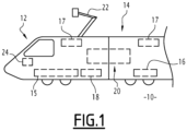
- FIG. 1 schematically represents a railway vehicle 10 according to one embodiment of the invention.
- the railway vehicle 10 for example of the train type, comprises a power unit 12 assembled with one or more cars 14, in particular intended to receive passengers.
- the railway vehicle 10 comprises at least one electric traction motor 15, equipping the power car 12.
- the motor 15 is in particular intended to operate under high voltage, in particular greater than 700V.
- the railway vehicle 10 further comprises first auxiliary electrical equipment 16, 17 intended to operate on a medium voltage network, of the 400V type.
- the first auxiliary electrical equipment includes for example one or more compressors 16 intended for inflating a pneumatic circuit of the vehicle 10, air conditioning devices 17 of cars 14 or even thermal equipment of the cold room type intended to preserve foodstuffs.
- the railway vehicle 10 further comprises second auxiliary electrical equipment 18 intended to operate on a low voltage network, of the 110V type.
- the second auxiliary electrical equipment 18 includes, for example, lighting and/or ventilation devices for cars 14, or even refrigerators.
- the railway vehicle 10 further comprises an electrical power supply device 20, connected to the auxiliary electrical equipment 16, 17, 18.
- the device 20 is capable of cooperating with an electrical power source external to the vehicle.
- the railway vehicle 10 comprises a pantograph 22 capable of supplying the device 20 with electricity coming from a catenary (not shown).
- the railway vehicle 10 further comprises an electronic control module 24, capable of controlling the device 20.
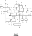
- FIG. 2 schematically represents several elements of the railway vehicle 10, in particular the electrical power supply device 20.
- Said device 20 comprises in particular an electrical converter 26, of the inverter type, a first input 28 of which is connected to the pantograph 22. Via a first output 27, the converter 26 is capable of supplying the motor 15 with high voltage current, in particular greater than 700V .
- the device 20 further comprises a first electrical storage member 30.
- said first member 30 is of the battery type and more preferably comprises at least one Lithium-Ion technology battery.
- said first member 30 has a significant capacity, of the order of 200 kWh.
- Lithium-Ion batteries make it possible to achieve high capacities for small volumes. In addition, they have a better lifespan than other Nickel-Cadmium or lead gel type technologies.
- the organ 30 is intended to store the energy of non-safety and comfort type consumers such as air conditioning equipment.
- the device 20 further comprises a first medium voltage electrical network 34, to which the first auxiliary electrical equipment 16, 17 is connected.
- the electrical converter 26 is capable of supplying said first network 34 with medium voltage current.
- the device 20 further comprises a first reversible charger 38.
- a first 40 and a second 42 reversible connections electrically connect said first charger 38, respectively to the first storage member 30 and to the first network 34.
- the first charger 38 is thus capable of transferring electricity in a reversible manner between said first storage member 30 and said first network 34.
- the device 20 further comprises a second low-voltage electrical network 44, to which the second auxiliary electrical equipment 18 is connected.
- the device 20 further comprises a second electrical storage member 46, comprising an output 47 connected to said second electrical network 44 so as to supply electricity to said network.
- said second member 46 is of the battery type and more preferably comprises at least one Lithium-Ion battery.
- the body 46 is intended to store the energy of security type consumers, of the emergency lighting and/or radio type, possibly required by a regulatory reference.
- the device 20 further comprises a second charger 48.
- An input 50 of said second charger 48 is connected to the first medium voltage electrical network 34.
- a first 52 and a second 54 outputs of said second charger 48 are connected respectively to the second electrical storage member 46 and to the second low voltage electrical network 44.
- the electronic control module 24 for example placed in a pilot cabin of the engine 12, is electronically connected to at least part of the aforementioned elements of the device 20 as will appear below.
- the electronic module 24 is connected to a GSM edge-to-ground type network, which allows it to receive updated information on the price of electricity available via the catenary.
- the electronic control module 24 is in particular equipped with programs capable of implementing these processes.
- nominal operation Said method is particularly implemented when the information received by the electronic module 24 indicates a cost lower than a predetermined threshold, for the electricity available via the catenary.
- the electrical converter 26 is powered by the catenary, via the pantograph 22 and the first input 28.
- the electrical converter 26 supplies the first medium voltage electrical network 34 and the first auxiliary electrical equipment 16, 17.
- Said first network 34 further supplies the second low voltage electrical network 44, via the second charger 48 and its second output 54.
- the first 40 and second 42 reversible connections of the first charger 38 and/or the first output 52 of the second charger 48 are configured to so as to supply electricity from said first network 34 to said first 30 and/or said second 46 organs.
- This second method is particularly implemented when the vehicle 10 is immobilized on a section of railway track not equipped with a catenary or immobilized following a catenary fault, in particular in a hot and sunny environment.
- the reversible charger 38 is powered via the connection 40, by the first electrical storage member 30.
- the electrical charger 38 supplies the first medium voltage electrical network 34 and the first auxiliary electrical equipment 16, 17, in particular the devices 17 car air conditioning 14.
- the supply of electricity for air conditioning requires significant power, which the reversible charger 38 is capable of providing.
- the second electrical network 44 is powered by the second storage member 46.
- said second network 44 is also partially powered by the first network 34, via the second charger 48 and its second release 54.
- the electrical converter 26 is powered by the catenary, via the pantograph 22, and powers for example the motor 15.
- the first 40 and second 42 reversible connections of the first charger 38 are configured so that said first organ 30 supplies electricity to the first electrical network medium voltage 34 and the first auxiliary electrical equipment 16, 17.
- the electricity taken by the pantograph 22 is assigned as a priority to the motor 15 in order to reduce the external consumption of the vehicle 10.
- the electronic module 24 manages the output 36 of the converter 26 so that the first network 34 takes electricity with priority from the first member 30 and, if necessary, in a non-priority manner from said converter 26.
- Said first network 34 also supplies the second low-voltage electrical network 44, via the second charger 48 and its second output 54.
- the unit 30 is then recharged when the electricity rate is outside the “peak hours” ranges.
- This fourth method is notably implemented when the vehicle 10 is parked, in particular on a site not equipped with a catenary.
- the motor 15 is stopped and the electric converter 26 is not powered.
- the first 40 and second 42 reversible connections of the first charger 38 are configured so that said first member 30 supplies electricity to the first medium voltage electrical network 34.
- the first output 52 of the second charger 48 is configured so as to supply electricity from said first network 34 to said second member 46 This method avoids equipping said second member 46 with a specific parking charging station.
- the first network 34 supplies some of the first auxiliary electrical equipment 16, 17, for example a cold room receiving foodstuffs.
- the first network 34 also supplies the second network 44 and some of the second auxiliary electrical equipment 18, for example refrigerators. This process makes it possible to keep perishable food in the parked vehicle 10, particularly in certain countries which do not allow the device 22 to be left connected overnight.
- the first to fourth methods described above can be implemented successively by the same vehicle.
- the rail vehicle according to the invention has better autonomy in cases where no external electrical power source is available.
- THE rail vehicle also makes it possible to reduce operating costs, by storing electricity and releasing it according to real-time changes in prices.
Landscapes
- Engineering & Computer Science (AREA)
- Power Engineering (AREA)
- Transportation (AREA)
- Mechanical Engineering (AREA)
- Life Sciences & Earth Sciences (AREA)
- Sustainable Development (AREA)
- Sustainable Energy (AREA)
- Electric Propulsion And Braking For Vehicles (AREA)
- Charge And Discharge Circuits For Batteries Or The Like (AREA)
Claims (7)
- Schienenfahrzeug (10) mit einer Stromversorgungsvorrichtung (20), einem elektrischen Fahrmotor (15), ersten elektrischen Hilfsausrüstungen (16, 17) und einem Verbindungselement (22) mit einer elektrischen Stromquelle außerhalb des Fahrzeugs, wobei die Stromversorgungsvorrichtung umfasst:- einen elektrischen Wandler (26), der mit dem Verbindungselement (22) verbunden ist;- ein erstes elektrisches Mittelspannungsnetz (34), an das die ersten elektrischen Hilfsausrüstungen angeschlossen sind; und- ein erstes elektrisches Speicherorgan (30), das mit dem ersten elektrischen Mittelspannungsnetz verbunden (40, 38, 42) ist, um dem ersten Netz Elektrizität zuzuführen oder zu entnehmen;der elektrische Wandler (26) einen ersten Ausgang (36) aufweist, der mit dem ersten elektrischen Mittelspannungsnetz verbunden ist, um dem ersten Netz Mittelspannungsstrom zuzuführen;das Schienenfahrzeug außerdem zweite elektrische Hilfsausrüstungen (18) umfasst, unddie Stromversorgungsvorrichtung ferner umfasst:- ein zweites Niederspannungsnetz (44), an das die zweiten Ausrüstungen angeschlossen sind; und- ein zweites elektrisches Speicherorgan (46), das mit dem zweiten Niederspannungsnetz verbunden (47) ist, um dem zweiten Netz Elektrizität zuzuführen;
wobei das zweite Speicherorgan außerdem mit dem ersten elektrischen Mittelspannungsnetz (34) verbunden ist (50, 48, 52), um Elektrizität aus dem ersten Netz zu entnehmen;wobei das Schienenfahrzeug dadurch gekennzeichnet ist, dass:- der elektrische Wandler ferner einen zweiten Ausgang (27) umfasst, der so konfiguriert ist, dass er den elektrischen Fahrmotor mit Hochspannungsstrom versorgt; und- die Stromversorgungsvorrichtung ein erstes umkehrbares Ladegerät (38) umfasst, das zwischen dem ersten elektrischen Speicherorgan (30) und dem ersten elektrischen Mittelspannungsnetz (34) angeordnet ist, wobei das erste Ladegerät dazu geeignet ist, Elektrizität von einem der ersten Organe und dem ersten Netz auf das andere zu übertragen. - Schienenfahrzeug nach Anspruch 1, bei dem das erste elektrische Speicherorgan (30) mindestens eine Lithium-Ionen-Batterie umfasst.
- Schienenfahrzeug nach Anspruch 1 oder 2, bei dem die Stromversorgungsvorrichtung eine zweites Ladegerät (48) umfasst, das zwischen dem ersten elektrischen Mittelspannungsnetz (34) und dem zweiten Speicherorgan (46) angeordnet ist, um das zweite Speicherorgan mit Elektrizität aus dem ersten Netz zu versorgen, wobei das zweite Ladegerät außerdem mit dem zweiten Niederspannungsnetz (44) verbunden (54) ist, um dem zweiten Netz Elektrizität zuzuführen, ohne das zweite Speicherorgan zu durchlaufen.
- Schienenfahrzeug nach einem der vorhergehenden Ansprüche, bei dem das zweite elektrische Speicherorgan (46) mindestens eine Lithium-Ionen-Batterie umfasst.
- Funktionsverfahren eines Schienenfahrzeugs nach einem der vorstehenden Ansprüche, wobei:- der elektrische Wandler (26) über das Verbindungselement (22) Elektrizität von einer elektrischen Stromquelle außerhalb des Fahrzeugs abzieht und Mittelspannungsstrom an das erste elektrische Mittelspannungsnetz (34) liefert; und- das erste elektrische Speicherorgan (30) Elektrizität aus dem ersten Netz entnimmt.
- Funktionsverfahren eines Schienenfahrzeugs nach einem der Ansprüche 1 bis 4, wobei:- der elektrische Wandler (26) über das Verbindungselement (22) Elektrizität von einer elektrischen Stromquelle außerhalb des Fahrzeugs abzieht und Hochspannungsstrom an den elektrischen Fahrmotor (15) liefert; und- das erste elektrische Speicherorgan (30) Elektrizität an das erste elektrische Mittelspannungsnetz (34) liefert.
- Funktionsverfahren eines Schienenfahrzeugs nach einem der Ansprüche 1 bis 4, wobei:- das erste elektrische Speicherorgan (30) Elektrizität an das erste elektrische Mittelspannungsnetz (34) liefert; und- das zweite elektrische Speicherorgan (46) Elektrizität aus dem ersten Netz entnimmt.
Applications Claiming Priority (1)
| Application Number | Priority Date | Filing Date | Title |
|---|---|---|---|
| FR1902289A FR3093492B1 (fr) | 2019-03-06 | 2019-03-06 | Véhicule ferroviaire équipé d’un organe de stockage électrique |
Publications (2)
| Publication Number | Publication Date |
|---|---|
| EP3705338A1 EP3705338A1 (de) | 2020-09-09 |
| EP3705338B1 true EP3705338B1 (de) | 2024-05-01 |
Family
ID=67441323
Family Applications (1)
| Application Number | Title | Priority Date | Filing Date |
|---|---|---|---|
| EP20161237.1A Active EP3705338B1 (de) | 2019-03-06 | 2020-03-05 | Schienenfahrzeug, das mit einem stromspeicherorgan ausgestattet ist |
Country Status (6)
| Country | Link |
|---|---|
| US (1) | US11760213B2 (de) |
| EP (1) | EP3705338B1 (de) |
| CN (1) | CN111660811B (de) |
| ES (1) | ES2981862T3 (de) |
| FR (1) | FR3093492B1 (de) |
| PL (1) | PL3705338T3 (de) |
Families Citing this family (3)
| Publication number | Priority date | Publication date | Assignee | Title |
|---|---|---|---|---|
| AT525936A1 (de) * | 2022-03-14 | 2023-09-15 | Siemens Mobility Austria Gmbh | Elektrische Energieversorgungseinrichtung für ein Schienenfahrzeug |
| FR3138105A1 (fr) * | 2022-07-20 | 2024-01-26 | Speedinnov | Ensemble de stockage d’énergie électrique et véhicule associé |
| EP4703229A1 (de) * | 2024-07-30 | 2026-03-04 | SpeedInnov | Schienenfahrzeug mit einer notbelüftungseinrichtung |
Citations (1)
| Publication number | Priority date | Publication date | Assignee | Title |
|---|---|---|---|---|
| US20170237372A1 (en) * | 2016-02-16 | 2017-08-17 | Electro-Motive Diesel, Inc. | Inverter module for a locomotive |
Family Cites Families (11)
| Publication number | Priority date | Publication date | Assignee | Title |
|---|---|---|---|---|
| DE102009008549A1 (de) * | 2009-02-12 | 2010-08-19 | Bombardier Transportation Gmbh | Anordnung zum Betreiben von Verbrauchern in einem Schienenfahrzeug mit elektrischer Energie, wahlweise aus einem Energieversorgungsnetz oder aus einer Motor-Generator-Kombination |
| JP5398634B2 (ja) * | 2010-05-12 | 2014-01-29 | 株式会社東芝 | 交流電気車 |
| US9008879B2 (en) | 2012-07-05 | 2015-04-14 | General Electric Company | System and method for operating a hybrid vehicle system |
| FR2995848B1 (fr) * | 2012-09-25 | 2015-05-15 | Renault Sa | Dispositif electrique auxiliaire pour vehicule automobile a traction electrique |
| JP5968518B2 (ja) * | 2013-03-06 | 2016-08-10 | 三菱電機株式会社 | 電気車用主変換装置 |
| DE102013205638B4 (de) * | 2013-03-28 | 2026-04-16 | Bayerische Motoren Werke Aktiengesellschaft | Fahrzeugbordnetz |
| DE102014200379A1 (de) * | 2014-01-13 | 2015-07-16 | Bayerische Motoren Werke Aktiengesellschaft | Ladevorrichtung für ein elektrisch angetriebenes Fahrzeug |
| FR3053937B1 (fr) * | 2016-07-12 | 2018-07-20 | Sncf Mobilites | Systeme d'alimentation electrique pour un vehicule ferroviaire et vehicule ferroviaire comprenant un tel systeme |
| EP3626489A1 (de) * | 2018-09-19 | 2020-03-25 | Thermo King Corporation | Verfahren und systeme zur energieverwaltung einer klimaanlage für transportfahrzeuge |
| CN109435974A (zh) * | 2018-09-26 | 2019-03-08 | 中车兰州机车有限公司 | 机车电气控制系统 |
| CN109383299B (zh) * | 2018-09-30 | 2020-03-10 | 中车青岛四方机车车辆股份有限公司 | 一种蓄电池应急供电系统、供电方法及轨道车辆 |
-
2019
- 2019-03-06 FR FR1902289A patent/FR3093492B1/fr active Active
-
2020
- 2020-03-04 CN CN202010142067.4A patent/CN111660811B/zh active Active
- 2020-03-05 EP EP20161237.1A patent/EP3705338B1/de active Active
- 2020-03-05 ES ES20161237T patent/ES2981862T3/es active Active
- 2020-03-05 PL PL20161237.1T patent/PL3705338T3/pl unknown
- 2020-03-06 US US16/812,072 patent/US11760213B2/en active Active
Patent Citations (1)
| Publication number | Priority date | Publication date | Assignee | Title |
|---|---|---|---|---|
| US20170237372A1 (en) * | 2016-02-16 | 2017-08-17 | Electro-Motive Diesel, Inc. | Inverter module for a locomotive |
Also Published As
| Publication number | Publication date |
|---|---|
| FR3093492B1 (fr) | 2025-03-07 |
| US20200282837A1 (en) | 2020-09-10 |
| EP3705338A1 (de) | 2020-09-09 |
| PL3705338T3 (pl) | 2024-08-26 |
| ES2981862T3 (es) | 2024-10-10 |
| FR3093492A1 (fr) | 2020-09-11 |
| CN111660811A (zh) | 2020-09-15 |
| CN111660811B (zh) | 2024-06-11 |
| US11760213B2 (en) | 2023-09-19 |
Similar Documents
| Publication | Publication Date | Title |
|---|---|---|
| US7928699B2 (en) | Battery charging time optimization system | |
| CN102015353B (zh) | 多发动机混合型机车 | |
| EP3705338B1 (de) | Schienenfahrzeug, das mit einem stromspeicherorgan ausgestattet ist | |
| EP1864846B2 (de) | Stromversorgungssystem und -verfahren für ein Schienenfahrzeug, Wandler, Steuereinheit, Klimaanlage für dieses System | |
| RU2389618C2 (ru) | Гибридная силовая установка (варианты) и способ управления мощностью гибридной силовой установки (варианты) | |
| US20170264136A1 (en) | Multiple Energy Accumulator System for Motor Vehicle Electrical Systems | |
| EP2309619A1 (de) | Schaltkreis zur reduzierung von ungleichgewichten, stromquellenvorrichtung und verfahren zur reduzierung von ungleichgewichten | |
| MX2007003288A (es) | Sistema de suministro de energia para una unidad de control de clima vehicular. | |
| EP2195533A1 (de) | Mit solarenergie aufgeladenes hybridenergiesystem | |
| CN102164772A (zh) | 用于控制运载工具能量存储装置的方法和系统 | |
| JP7048313B2 (ja) | 鉄道車両に備えられた蓄電装置の充放電を制御する制御装置及び制御方法 | |
| EP3424123B1 (de) | Verfahren und system zur regelung eines versorgungsstromes eines batteriepacks | |
| US9321366B1 (en) | Electric vehicle charging by adjusting charger current | |
| US20130181679A1 (en) | Passenger bus with on-board charger | |
| US12275315B2 (en) | Hybrid power management system and method for delivering power in a transport vehicle | |
| CN110949131A (zh) | 车辆电气负载甩负荷 | |
| KR20200129264A (ko) | 전기자동차 부품의 보호 및 전력 분배 장치 | |
| JP2007022211A (ja) | 車両用電源装置 | |
| US11635477B2 (en) | Continuous onboard re-charge environment | |
| US20230020971A1 (en) | Method for controlling power transfer from a grid to a vehicle | |
| CN120534148A (zh) | 采暖控制器及采暖系统、采暖控制方法、电子设备、车辆和存储介质 | |
| WO2020002820A1 (fr) | Système de stockage d'énergie embarqué | |
| FR2897018A1 (fr) | Rame de metro. | |
| FR2942357A1 (fr) | Systeme et procede de gestion de recharge d'une batterie | |
| MXPA06015111A (en) | Hybrid electric propulsion system and method |
Legal Events
| Date | Code | Title | Description |
|---|---|---|---|
| PUAI | Public reference made under article 153(3) epc to a published international application that has entered the european phase |
Free format text: ORIGINAL CODE: 0009012 |
|
| STAA | Information on the status of an ep patent application or granted ep patent |
Free format text: STATUS: THE APPLICATION HAS BEEN PUBLISHED |
|
| AK | Designated contracting states |
Kind code of ref document: A1 Designated state(s): AL AT BE BG CH CY CZ DE DK EE ES FI FR GB GR HR HU IE IS IT LI LT LU LV MC MK MT NL NO PL PT RO RS SE SI SK SM TR |
|
| AX | Request for extension of the european patent |
Extension state: BA ME |
|
| STAA | Information on the status of an ep patent application or granted ep patent |
Free format text: STATUS: REQUEST FOR EXAMINATION WAS MADE |
|
| 17P | Request for examination filed |
Effective date: 20200910 |
|
| RBV | Designated contracting states (corrected) |
Designated state(s): AL AT BE BG CH CY CZ DE DK EE ES FI FR GB GR HR HU IE IS IT LI LT LU LV MC MK MT NL NO PL PT RO RS SE SI SK SM TR |
|
| STAA | Information on the status of an ep patent application or granted ep patent |
Free format text: STATUS: EXAMINATION IS IN PROGRESS |
|
| 17Q | First examination report despatched |
Effective date: 20220117 |
|
| GRAP | Despatch of communication of intention to grant a patent |
Free format text: ORIGINAL CODE: EPIDOSNIGR1 |
|
| STAA | Information on the status of an ep patent application or granted ep patent |
Free format text: STATUS: GRANT OF PATENT IS INTENDED |
|
| P01 | Opt-out of the competence of the unified patent court (upc) registered |
Effective date: 20231026 |
|
| INTG | Intention to grant announced |
Effective date: 20231124 |
|
| GRAS | Grant fee paid |
Free format text: ORIGINAL CODE: EPIDOSNIGR3 |
|
| GRAA | (expected) grant |
Free format text: ORIGINAL CODE: 0009210 |
|
| STAA | Information on the status of an ep patent application or granted ep patent |
Free format text: STATUS: THE PATENT HAS BEEN GRANTED |
|
| AK | Designated contracting states |
Kind code of ref document: B1 Designated state(s): AL AT BE BG CH CY CZ DE DK EE ES FI FR GB GR HR HU IE IS IT LI LT LU LV MC MK MT NL NO PL PT RO RS SE SI SK SM TR |
|
| REG | Reference to a national code |
Ref country code: GB Ref legal event code: FG4D Free format text: NOT ENGLISH |
|
| REG | Reference to a national code |
Ref country code: CH Ref legal event code: EP |
|
| REG | Reference to a national code |
Ref country code: IE Ref legal event code: FG4D Free format text: LANGUAGE OF EP DOCUMENT: FRENCH |
|
| REG | Reference to a national code |
Ref country code: DE Ref legal event code: R096 Ref document number: 602020029888 Country of ref document: DE |
|
| REG | Reference to a national code |
Ref country code: SE Ref legal event code: TRGR |
|
| REG | Reference to a national code |
Ref country code: LT Ref legal event code: MG9D |
|
| REG | Reference to a national code |
Ref country code: NL Ref legal event code: MP Effective date: 20240501 |
|
| PG25 | Lapsed in a contracting state [announced via postgrant information from national office to epo] |
Ref country code: IS Free format text: LAPSE BECAUSE OF FAILURE TO SUBMIT A TRANSLATION OF THE DESCRIPTION OR TO PAY THE FEE WITHIN THE PRESCRIBED TIME-LIMIT Effective date: 20240901 |
|
| PG25 | Lapsed in a contracting state [announced via postgrant information from national office to epo] |
Ref country code: BG Free format text: LAPSE BECAUSE OF FAILURE TO SUBMIT A TRANSLATION OF THE DESCRIPTION OR TO PAY THE FEE WITHIN THE PRESCRIBED TIME-LIMIT Effective date: 20240501 |
|
| PG25 | Lapsed in a contracting state [announced via postgrant information from national office to epo] |
Ref country code: HR Free format text: LAPSE BECAUSE OF FAILURE TO SUBMIT A TRANSLATION OF THE DESCRIPTION OR TO PAY THE FEE WITHIN THE PRESCRIBED TIME-LIMIT Effective date: 20240501 Ref country code: FI Free format text: LAPSE BECAUSE OF FAILURE TO SUBMIT A TRANSLATION OF THE DESCRIPTION OR TO PAY THE FEE WITHIN THE PRESCRIBED TIME-LIMIT Effective date: 20240501 |
|
| REG | Reference to a national code |
Ref country code: ES Ref legal event code: FG2A Ref document number: 2981862 Country of ref document: ES Kind code of ref document: T3 Effective date: 20241010 |
|
| PG25 | Lapsed in a contracting state [announced via postgrant information from national office to epo] |
Ref country code: GR Free format text: LAPSE BECAUSE OF FAILURE TO SUBMIT A TRANSLATION OF THE DESCRIPTION OR TO PAY THE FEE WITHIN THE PRESCRIBED TIME-LIMIT Effective date: 20240802 |
|
| PG25 | Lapsed in a contracting state [announced via postgrant information from national office to epo] |
Ref country code: PT Free format text: LAPSE BECAUSE OF FAILURE TO SUBMIT A TRANSLATION OF THE DESCRIPTION OR TO PAY THE FEE WITHIN THE PRESCRIBED TIME-LIMIT Effective date: 20240902 |
|
| REG | Reference to a national code |
Ref country code: AT Ref legal event code: MK05 Ref document number: 1681913 Country of ref document: AT Kind code of ref document: T Effective date: 20240501 |
|
| PG25 | Lapsed in a contracting state [announced via postgrant information from national office to epo] |
Ref country code: NL Free format text: LAPSE BECAUSE OF FAILURE TO SUBMIT A TRANSLATION OF THE DESCRIPTION OR TO PAY THE FEE WITHIN THE PRESCRIBED TIME-LIMIT Effective date: 20240501 |
|
| PG25 | Lapsed in a contracting state [announced via postgrant information from national office to epo] |
Ref country code: AT Free format text: LAPSE BECAUSE OF FAILURE TO SUBMIT A TRANSLATION OF THE DESCRIPTION OR TO PAY THE FEE WITHIN THE PRESCRIBED TIME-LIMIT Effective date: 20240501 |
|
| PG25 | Lapsed in a contracting state [announced via postgrant information from national office to epo] |
Ref country code: LV Free format text: LAPSE BECAUSE OF FAILURE TO SUBMIT A TRANSLATION OF THE DESCRIPTION OR TO PAY THE FEE WITHIN THE PRESCRIBED TIME-LIMIT Effective date: 20240501 |
|
| PG25 | Lapsed in a contracting state [announced via postgrant information from national office to epo] |
Ref country code: PT Free format text: LAPSE BECAUSE OF FAILURE TO SUBMIT A TRANSLATION OF THE DESCRIPTION OR TO PAY THE FEE WITHIN THE PRESCRIBED TIME-LIMIT Effective date: 20240902 Ref country code: NO Free format text: LAPSE BECAUSE OF FAILURE TO SUBMIT A TRANSLATION OF THE DESCRIPTION OR TO PAY THE FEE WITHIN THE PRESCRIBED TIME-LIMIT Effective date: 20240801 Ref country code: NL Free format text: LAPSE BECAUSE OF FAILURE TO SUBMIT A TRANSLATION OF THE DESCRIPTION OR TO PAY THE FEE WITHIN THE PRESCRIBED TIME-LIMIT Effective date: 20240501 Ref country code: LV Free format text: LAPSE BECAUSE OF FAILURE TO SUBMIT A TRANSLATION OF THE DESCRIPTION OR TO PAY THE FEE WITHIN THE PRESCRIBED TIME-LIMIT Effective date: 20240501 Ref country code: IS Free format text: LAPSE BECAUSE OF FAILURE TO SUBMIT A TRANSLATION OF THE DESCRIPTION OR TO PAY THE FEE WITHIN THE PRESCRIBED TIME-LIMIT Effective date: 20240901 Ref country code: HR Free format text: LAPSE BECAUSE OF FAILURE TO SUBMIT A TRANSLATION OF THE DESCRIPTION OR TO PAY THE FEE WITHIN THE PRESCRIBED TIME-LIMIT Effective date: 20240501 Ref country code: GR Free format text: LAPSE BECAUSE OF FAILURE TO SUBMIT A TRANSLATION OF THE DESCRIPTION OR TO PAY THE FEE WITHIN THE PRESCRIBED TIME-LIMIT Effective date: 20240802 Ref country code: FI Free format text: LAPSE BECAUSE OF FAILURE TO SUBMIT A TRANSLATION OF THE DESCRIPTION OR TO PAY THE FEE WITHIN THE PRESCRIBED TIME-LIMIT Effective date: 20240501 Ref country code: BG Free format text: LAPSE BECAUSE OF FAILURE TO SUBMIT A TRANSLATION OF THE DESCRIPTION OR TO PAY THE FEE WITHIN THE PRESCRIBED TIME-LIMIT Effective date: 20240501 Ref country code: AT Free format text: LAPSE BECAUSE OF FAILURE TO SUBMIT A TRANSLATION OF THE DESCRIPTION OR TO PAY THE FEE WITHIN THE PRESCRIBED TIME-LIMIT Effective date: 20240501 Ref country code: RS Free format text: LAPSE BECAUSE OF FAILURE TO SUBMIT A TRANSLATION OF THE DESCRIPTION OR TO PAY THE FEE WITHIN THE PRESCRIBED TIME-LIMIT Effective date: 20240801 |
|
| PG25 | Lapsed in a contracting state [announced via postgrant information from national office to epo] |
Ref country code: DK Free format text: LAPSE BECAUSE OF FAILURE TO SUBMIT A TRANSLATION OF THE DESCRIPTION OR TO PAY THE FEE WITHIN THE PRESCRIBED TIME-LIMIT Effective date: 20240501 |
|
| PG25 | Lapsed in a contracting state [announced via postgrant information from national office to epo] |
Ref country code: EE Free format text: LAPSE BECAUSE OF FAILURE TO SUBMIT A TRANSLATION OF THE DESCRIPTION OR TO PAY THE FEE WITHIN THE PRESCRIBED TIME-LIMIT Effective date: 20240501 |
|
| PG25 | Lapsed in a contracting state [announced via postgrant information from national office to epo] |
Ref country code: CZ Free format text: LAPSE BECAUSE OF FAILURE TO SUBMIT A TRANSLATION OF THE DESCRIPTION OR TO PAY THE FEE WITHIN THE PRESCRIBED TIME-LIMIT Effective date: 20240501 |
|
| PG25 | Lapsed in a contracting state [announced via postgrant information from national office to epo] |
Ref country code: RO Free format text: LAPSE BECAUSE OF FAILURE TO SUBMIT A TRANSLATION OF THE DESCRIPTION OR TO PAY THE FEE WITHIN THE PRESCRIBED TIME-LIMIT Effective date: 20240501 Ref country code: SK Free format text: LAPSE BECAUSE OF FAILURE TO SUBMIT A TRANSLATION OF THE DESCRIPTION OR TO PAY THE FEE WITHIN THE PRESCRIBED TIME-LIMIT Effective date: 20240501 |
|
| PG25 | Lapsed in a contracting state [announced via postgrant information from national office to epo] |
Ref country code: SM Free format text: LAPSE BECAUSE OF FAILURE TO SUBMIT A TRANSLATION OF THE DESCRIPTION OR TO PAY THE FEE WITHIN THE PRESCRIBED TIME-LIMIT Effective date: 20240501 |
|
| PG25 | Lapsed in a contracting state [announced via postgrant information from national office to epo] |
Ref country code: SM Free format text: LAPSE BECAUSE OF FAILURE TO SUBMIT A TRANSLATION OF THE DESCRIPTION OR TO PAY THE FEE WITHIN THE PRESCRIBED TIME-LIMIT Effective date: 20240501 Ref country code: SK Free format text: LAPSE BECAUSE OF FAILURE TO SUBMIT A TRANSLATION OF THE DESCRIPTION OR TO PAY THE FEE WITHIN THE PRESCRIBED TIME-LIMIT Effective date: 20240501 Ref country code: RO Free format text: LAPSE BECAUSE OF FAILURE TO SUBMIT A TRANSLATION OF THE DESCRIPTION OR TO PAY THE FEE WITHIN THE PRESCRIBED TIME-LIMIT Effective date: 20240501 Ref country code: EE Free format text: LAPSE BECAUSE OF FAILURE TO SUBMIT A TRANSLATION OF THE DESCRIPTION OR TO PAY THE FEE WITHIN THE PRESCRIBED TIME-LIMIT Effective date: 20240501 Ref country code: DK Free format text: LAPSE BECAUSE OF FAILURE TO SUBMIT A TRANSLATION OF THE DESCRIPTION OR TO PAY THE FEE WITHIN THE PRESCRIBED TIME-LIMIT Effective date: 20240501 Ref country code: CZ Free format text: LAPSE BECAUSE OF FAILURE TO SUBMIT A TRANSLATION OF THE DESCRIPTION OR TO PAY THE FEE WITHIN THE PRESCRIBED TIME-LIMIT Effective date: 20240501 |
|
| REG | Reference to a national code |
Ref country code: DE Ref legal event code: R097 Ref document number: 602020029888 Country of ref document: DE |
|
| PLBE | No opposition filed within time limit |
Free format text: ORIGINAL CODE: 0009261 |
|
| STAA | Information on the status of an ep patent application or granted ep patent |
Free format text: STATUS: NO OPPOSITION FILED WITHIN TIME LIMIT |
|
| 26N | No opposition filed |
Effective date: 20250204 |
|
| PG25 | Lapsed in a contracting state [announced via postgrant information from national office to epo] |
Ref country code: SI Free format text: LAPSE BECAUSE OF FAILURE TO SUBMIT A TRANSLATION OF THE DESCRIPTION OR TO PAY THE FEE WITHIN THE PRESCRIBED TIME-LIMIT Effective date: 20240501 |
|
| PGFP | Annual fee paid to national office [announced via postgrant information from national office to epo] |
Ref country code: PL Payment date: 20250225 Year of fee payment: 6 |
|
| PGFP | Annual fee paid to national office [announced via postgrant information from national office to epo] |
Ref country code: ES Payment date: 20250429 Year of fee payment: 6 |
|
| PGFP | Annual fee paid to national office [announced via postgrant information from national office to epo] |
Ref country code: CH Payment date: 20250401 Year of fee payment: 6 |
|
| PG25 | Lapsed in a contracting state [announced via postgrant information from national office to epo] |
Ref country code: MC Free format text: LAPSE BECAUSE OF FAILURE TO SUBMIT A TRANSLATION OF THE DESCRIPTION OR TO PAY THE FEE WITHIN THE PRESCRIBED TIME-LIMIT Effective date: 20240501 |
|
| PG25 | Lapsed in a contracting state [announced via postgrant information from national office to epo] |
Ref country code: LU Free format text: LAPSE BECAUSE OF NON-PAYMENT OF DUE FEES Effective date: 20250305 |
|
| PG25 | Lapsed in a contracting state [announced via postgrant information from national office to epo] |
Ref country code: IE Free format text: LAPSE BECAUSE OF NON-PAYMENT OF DUE FEES Effective date: 20250305 |
|
| REG | Reference to a national code |
Ref country code: CH Ref legal event code: U11 Free format text: ST27 STATUS EVENT CODE: U-0-0-U10-U11 (AS PROVIDED BY THE NATIONAL OFFICE) Effective date: 20260401 |
|
| PGFP | Annual fee paid to national office [announced via postgrant information from national office to epo] |
Ref country code: SE Payment date: 20260319 Year of fee payment: 7 |
|
| PGFP | Annual fee paid to national office [announced via postgrant information from national office to epo] |
Ref country code: GB Payment date: 20260324 Year of fee payment: 7 |
|
| PGFP | Annual fee paid to national office [announced via postgrant information from national office to epo] |
Ref country code: DE Payment date: 20260319 Year of fee payment: 7 |
|
| PGFP | Annual fee paid to national office [announced via postgrant information from national office to epo] |
Ref country code: BE Payment date: 20260319 Year of fee payment: 7 Ref country code: IT Payment date: 20260324 Year of fee payment: 7 |
|
| PGFP | Annual fee paid to national office [announced via postgrant information from national office to epo] |
Ref country code: FR Payment date: 20260320 Year of fee payment: 7 |
|
| PGFP | Annual fee paid to national office [announced via postgrant information from national office to epo] |
Ref country code: TR Payment date: 20260226 Year of fee payment: 7 |