EP3705338B1 - Railway vehicle provided with an electric storage member - Google Patents
Railway vehicle provided with an electric storage member Download PDFInfo
- Publication number
- EP3705338B1 EP3705338B1 EP20161237.1A EP20161237A EP3705338B1 EP 3705338 B1 EP3705338 B1 EP 3705338B1 EP 20161237 A EP20161237 A EP 20161237A EP 3705338 B1 EP3705338 B1 EP 3705338B1
- Authority
- EP
- European Patent Office
- Prior art keywords
- network
- electricity
- electrical
- storage element
- railway vehicle
- Prior art date
- Legal status (The legal status is an assumption and is not a legal conclusion. Google has not performed a legal analysis and makes no representation as to the accuracy of the status listed.)
- Active
Links
- 230000005611 electricity Effects 0.000 claims description 57
- 238000000034 method Methods 0.000 claims description 27
- 230000002441 reversible effect Effects 0.000 claims description 10
- HBBGRARXTFLTSG-UHFFFAOYSA-N Lithium ion Chemical compound [Li+] HBBGRARXTFLTSG-UHFFFAOYSA-N 0.000 claims description 9
- 229910001416 lithium ion Inorganic materials 0.000 claims description 9
- 238000004378 air conditioning Methods 0.000 description 6
- 238000012550 audit Methods 0.000 description 4
- 210000000056 organ Anatomy 0.000 description 4
- 238000005516 engineering process Methods 0.000 description 2
- 241000287107 Passer Species 0.000 description 1
- OJIJEKBXJYRIBZ-UHFFFAOYSA-N cadmium nickel Chemical compound [Ni].[Cd] OJIJEKBXJYRIBZ-UHFFFAOYSA-N 0.000 description 1
- 230000001276 controlling effect Effects 0.000 description 1
- 238000009499 grossing Methods 0.000 description 1
- 230000001105 regulatory effect Effects 0.000 description 1
- 238000009423 ventilation Methods 0.000 description 1
- 210000001835 viscera Anatomy 0.000 description 1
Images
Classifications
-
- B—PERFORMING OPERATIONS; TRANSPORTING
- B60—VEHICLES IN GENERAL
- B60L—PROPULSION OF ELECTRICALLY-PROPELLED VEHICLES; SUPPLYING ELECTRIC POWER FOR AUXILIARY EQUIPMENT OF ELECTRICALLY-PROPELLED VEHICLES; ELECTRODYNAMIC BRAKE SYSTEMS FOR VEHICLES IN GENERAL; MAGNETIC SUSPENSION OR LEVITATION FOR VEHICLES; MONITORING OPERATING VARIABLES OF ELECTRICALLY-PROPELLED VEHICLES; ELECTRIC SAFETY DEVICES FOR ELECTRICALLY-PROPELLED VEHICLES
- B60L50/00—Electric propulsion with power supplied within the vehicle
- B60L50/50—Electric propulsion with power supplied within the vehicle using propulsion power supplied by batteries or fuel cells
- B60L50/53—Electric propulsion with power supplied within the vehicle using propulsion power supplied by batteries or fuel cells in combination with an external power supply, e.g. from overhead contact lines
-
- B—PERFORMING OPERATIONS; TRANSPORTING
- B60—VEHICLES IN GENERAL
- B60L—PROPULSION OF ELECTRICALLY-PROPELLED VEHICLES; SUPPLYING ELECTRIC POWER FOR AUXILIARY EQUIPMENT OF ELECTRICALLY-PROPELLED VEHICLES; ELECTRODYNAMIC BRAKE SYSTEMS FOR VEHICLES IN GENERAL; MAGNETIC SUSPENSION OR LEVITATION FOR VEHICLES; MONITORING OPERATING VARIABLES OF ELECTRICALLY-PROPELLED VEHICLES; ELECTRIC SAFETY DEVICES FOR ELECTRICALLY-PROPELLED VEHICLES
- B60L1/00—Supplying electric power to auxiliary equipment of vehicles
- B60L1/02—Supplying electric power to auxiliary equipment of vehicles to electric heating circuits
-
- B—PERFORMING OPERATIONS; TRANSPORTING
- B60—VEHICLES IN GENERAL
- B60L—PROPULSION OF ELECTRICALLY-PROPELLED VEHICLES; SUPPLYING ELECTRIC POWER FOR AUXILIARY EQUIPMENT OF ELECTRICALLY-PROPELLED VEHICLES; ELECTRODYNAMIC BRAKE SYSTEMS FOR VEHICLES IN GENERAL; MAGNETIC SUSPENSION OR LEVITATION FOR VEHICLES; MONITORING OPERATING VARIABLES OF ELECTRICALLY-PROPELLED VEHICLES; ELECTRIC SAFETY DEVICES FOR ELECTRICALLY-PROPELLED VEHICLES
- B60L1/00—Supplying electric power to auxiliary equipment of vehicles
- B60L1/003—Supplying electric power to auxiliary equipment of vehicles to auxiliary motors, e.g. for pumps, compressors
-
- B—PERFORMING OPERATIONS; TRANSPORTING
- B60—VEHICLES IN GENERAL
- B60L—PROPULSION OF ELECTRICALLY-PROPELLED VEHICLES; SUPPLYING ELECTRIC POWER FOR AUXILIARY EQUIPMENT OF ELECTRICALLY-PROPELLED VEHICLES; ELECTRODYNAMIC BRAKE SYSTEMS FOR VEHICLES IN GENERAL; MAGNETIC SUSPENSION OR LEVITATION FOR VEHICLES; MONITORING OPERATING VARIABLES OF ELECTRICALLY-PROPELLED VEHICLES; ELECTRIC SAFETY DEVICES FOR ELECTRICALLY-PROPELLED VEHICLES
- B60L1/00—Supplying electric power to auxiliary equipment of vehicles
- B60L1/14—Supplying electric power to auxiliary equipment of vehicles to electric lighting circuits
-
- B—PERFORMING OPERATIONS; TRANSPORTING
- B60—VEHICLES IN GENERAL
- B60L—PROPULSION OF ELECTRICALLY-PROPELLED VEHICLES; SUPPLYING ELECTRIC POWER FOR AUXILIARY EQUIPMENT OF ELECTRICALLY-PROPELLED VEHICLES; ELECTRODYNAMIC BRAKE SYSTEMS FOR VEHICLES IN GENERAL; MAGNETIC SUSPENSION OR LEVITATION FOR VEHICLES; MONITORING OPERATING VARIABLES OF ELECTRICALLY-PROPELLED VEHICLES; ELECTRIC SAFETY DEVICES FOR ELECTRICALLY-PROPELLED VEHICLES
- B60L5/00—Current collectors for power supply lines of electrically-propelled vehicles
- B60L5/18—Current collectors for power supply lines of electrically-propelled vehicles using bow-type collectors in contact with trolley wire
-
- B—PERFORMING OPERATIONS; TRANSPORTING
- B60—VEHICLES IN GENERAL
- B60L—PROPULSION OF ELECTRICALLY-PROPELLED VEHICLES; SUPPLYING ELECTRIC POWER FOR AUXILIARY EQUIPMENT OF ELECTRICALLY-PROPELLED VEHICLES; ELECTRODYNAMIC BRAKE SYSTEMS FOR VEHICLES IN GENERAL; MAGNETIC SUSPENSION OR LEVITATION FOR VEHICLES; MONITORING OPERATING VARIABLES OF ELECTRICALLY-PROPELLED VEHICLES; ELECTRIC SAFETY DEVICES FOR ELECTRICALLY-PROPELLED VEHICLES
- B60L9/00—Electric propulsion with power supply external to the vehicle
-
- B—PERFORMING OPERATIONS; TRANSPORTING
- B61—RAILWAYS
- B61C—LOCOMOTIVES; MOTOR RAILCARS
- B61C3/00—Electric locomotives or railcars
- B61C3/02—Electric locomotives or railcars with electric accumulators
-
- B—PERFORMING OPERATIONS; TRANSPORTING
- B60—VEHICLES IN GENERAL
- B60L—PROPULSION OF ELECTRICALLY-PROPELLED VEHICLES; SUPPLYING ELECTRIC POWER FOR AUXILIARY EQUIPMENT OF ELECTRICALLY-PROPELLED VEHICLES; ELECTRODYNAMIC BRAKE SYSTEMS FOR VEHICLES IN GENERAL; MAGNETIC SUSPENSION OR LEVITATION FOR VEHICLES; MONITORING OPERATING VARIABLES OF ELECTRICALLY-PROPELLED VEHICLES; ELECTRIC SAFETY DEVICES FOR ELECTRICALLY-PROPELLED VEHICLES
- B60L2200/00—Type of vehicles
- B60L2200/26—Rail vehicles
-
- Y—GENERAL TAGGING OF NEW TECHNOLOGICAL DEVELOPMENTS; GENERAL TAGGING OF CROSS-SECTIONAL TECHNOLOGIES SPANNING OVER SEVERAL SECTIONS OF THE IPC; TECHNICAL SUBJECTS COVERED BY FORMER USPC CROSS-REFERENCE ART COLLECTIONS [XRACs] AND DIGESTS
- Y02—TECHNOLOGIES OR APPLICATIONS FOR MITIGATION OR ADAPTATION AGAINST CLIMATE CHANGE
- Y02T—CLIMATE CHANGE MITIGATION TECHNOLOGIES RELATED TO TRANSPORTATION
- Y02T10/00—Road transport of goods or passengers
- Y02T10/60—Other road transportation technologies with climate change mitigation effect
- Y02T10/70—Energy storage systems for electromobility, e.g. batteries
-
- Y—GENERAL TAGGING OF NEW TECHNOLOGICAL DEVELOPMENTS; GENERAL TAGGING OF CROSS-SECTIONAL TECHNOLOGIES SPANNING OVER SEVERAL SECTIONS OF THE IPC; TECHNICAL SUBJECTS COVERED BY FORMER USPC CROSS-REFERENCE ART COLLECTIONS [XRACs] AND DIGESTS
- Y02—TECHNOLOGIES OR APPLICATIONS FOR MITIGATION OR ADAPTATION AGAINST CLIMATE CHANGE
- Y02T—CLIMATE CHANGE MITIGATION TECHNOLOGIES RELATED TO TRANSPORTATION
- Y02T10/00—Road transport of goods or passengers
- Y02T10/60—Other road transportation technologies with climate change mitigation effect
- Y02T10/7072—Electromobility specific charging systems or methods for batteries, ultracapacitors, supercapacitors or double-layer capacitors
-
- Y—GENERAL TAGGING OF NEW TECHNOLOGICAL DEVELOPMENTS; GENERAL TAGGING OF CROSS-SECTIONAL TECHNOLOGIES SPANNING OVER SEVERAL SECTIONS OF THE IPC; TECHNICAL SUBJECTS COVERED BY FORMER USPC CROSS-REFERENCE ART COLLECTIONS [XRACs] AND DIGESTS
- Y02—TECHNOLOGIES OR APPLICATIONS FOR MITIGATION OR ADAPTATION AGAINST CLIMATE CHANGE
- Y02T—CLIMATE CHANGE MITIGATION TECHNOLOGIES RELATED TO TRANSPORTATION
- Y02T30/00—Transportation of goods or passengers via railways, e.g. energy recovery or reducing air resistance
-
- Y—GENERAL TAGGING OF NEW TECHNOLOGICAL DEVELOPMENTS; GENERAL TAGGING OF CROSS-SECTIONAL TECHNOLOGIES SPANNING OVER SEVERAL SECTIONS OF THE IPC; TECHNICAL SUBJECTS COVERED BY FORMER USPC CROSS-REFERENCE ART COLLECTIONS [XRACs] AND DIGESTS
- Y02—TECHNOLOGIES OR APPLICATIONS FOR MITIGATION OR ADAPTATION AGAINST CLIMATE CHANGE
- Y02T—CLIMATE CHANGE MITIGATION TECHNOLOGIES RELATED TO TRANSPORTATION
- Y02T90/00—Enabling technologies or technologies with a potential or indirect contribution to GHG emissions mitigation
- Y02T90/10—Technologies relating to charging of electric vehicles
- Y02T90/14—Plug-in electric vehicles
Definitions
- the present invention relates to a railway vehicle, of the type comprising an electrical power supply device, an electric traction motor, first auxiliary electrical equipment and an element for connecting to an electrical power source external to the vehicle, said power supply device comprising : an electric converter capable of supplying the electric traction motor with high voltage current; said electrical converter being connected to the connection element; a first medium voltage electrical network to which the first auxiliary electrical equipment is connected; and a first electrical storage unit, connected to the first medium voltage electrical network, so as to supply or draw electricity from said first network.
- Auxiliary functions such as air conditioning in passenger cars require significant electrical power. Their supply by internal storage organs involves constraints and high costs for the vehicle's electrical power supply device.
- the present invention aims to solve this problem.
- the subject of the invention is a railway vehicle of the aforementioned type, conforming to the characteristics of claim 1.
- the invention further relates to a method of operating a railway vehicle as described above.
- the method is such that: the electrical converter takes electricity from an electrical power source external to the vehicle, via the connection element, and supplies electricity to the first medium voltage electrical network; and the first electrical storage member draws electricity from said first network.
- the method is such that: the electrical converter takes electricity from an electrical power source external to the vehicle, via the connection element, and supplies electricity to the electric traction motor; and the first electrical storage member supplies electricity to the first medium voltage electrical network.
- the method is such that: the first electrical storage member supplies electricity to the first medium voltage electrical network; and the second electrical storage member draws electricity from said first network.
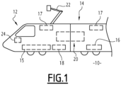
- FIG. 1 schematically represents a railway vehicle 10 according to one embodiment of the invention.
- the railway vehicle 10 for example of the train type, comprises a power unit 12 assembled with one or more cars 14, in particular intended to receive passengers.
- the railway vehicle 10 comprises at least one electric traction motor 15, equipping the power car 12.
- the motor 15 is in particular intended to operate under high voltage, in particular greater than 700V.
- the railway vehicle 10 further comprises first auxiliary electrical equipment 16, 17 intended to operate on a medium voltage network, of the 400V type.
- the first auxiliary electrical equipment includes for example one or more compressors 16 intended for inflating a pneumatic circuit of the vehicle 10, air conditioning devices 17 of cars 14 or even thermal equipment of the cold room type intended to preserve foodstuffs.
- the railway vehicle 10 further comprises second auxiliary electrical equipment 18 intended to operate on a low voltage network, of the 110V type.
- the second auxiliary electrical equipment 18 includes, for example, lighting and/or ventilation devices for cars 14, or even refrigerators.
- the railway vehicle 10 further comprises an electrical power supply device 20, connected to the auxiliary electrical equipment 16, 17, 18.
- the device 20 is capable of cooperating with an electrical power source external to the vehicle.
- the railway vehicle 10 comprises a pantograph 22 capable of supplying the device 20 with electricity coming from a catenary (not shown).
- the railway vehicle 10 further comprises an electronic control module 24, capable of controlling the device 20.
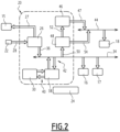
- FIG. 2 schematically represents several elements of the railway vehicle 10, in particular the electrical power supply device 20.
- Said device 20 comprises in particular an electrical converter 26, of the inverter type, a first input 28 of which is connected to the pantograph 22. Via a first output 27, the converter 26 is capable of supplying the motor 15 with high voltage current, in particular greater than 700V .
- the device 20 further comprises a first electrical storage member 30.
- said first member 30 is of the battery type and more preferably comprises at least one Lithium-Ion technology battery.
- said first member 30 has a significant capacity, of the order of 200 kWh.
- Lithium-Ion batteries make it possible to achieve high capacities for small volumes. In addition, they have a better lifespan than other Nickel-Cadmium or lead gel type technologies.
- the organ 30 is intended to store the energy of non-safety and comfort type consumers such as air conditioning equipment.
- the device 20 further comprises a first medium voltage electrical network 34, to which the first auxiliary electrical equipment 16, 17 is connected.
- the electrical converter 26 is capable of supplying said first network 34 with medium voltage current.
- the device 20 further comprises a first reversible charger 38.
- a first 40 and a second 42 reversible connections electrically connect said first charger 38, respectively to the first storage member 30 and to the first network 34.
- the first charger 38 is thus capable of transferring electricity in a reversible manner between said first storage member 30 and said first network 34.
- the device 20 further comprises a second low-voltage electrical network 44, to which the second auxiliary electrical equipment 18 is connected.
- the device 20 further comprises a second electrical storage member 46, comprising an output 47 connected to said second electrical network 44 so as to supply electricity to said network.
- said second member 46 is of the battery type and more preferably comprises at least one Lithium-Ion battery.
- the body 46 is intended to store the energy of security type consumers, of the emergency lighting and/or radio type, possibly required by a regulatory reference.
- the device 20 further comprises a second charger 48.
- An input 50 of said second charger 48 is connected to the first medium voltage electrical network 34.
- a first 52 and a second 54 outputs of said second charger 48 are connected respectively to the second electrical storage member 46 and to the second low voltage electrical network 44.
- the electronic control module 24 for example placed in a pilot cabin of the engine 12, is electronically connected to at least part of the aforementioned elements of the device 20 as will appear below.
- the electronic module 24 is connected to a GSM edge-to-ground type network, which allows it to receive updated information on the price of electricity available via the catenary.
- the electronic control module 24 is in particular equipped with programs capable of implementing these processes.
- nominal operation Said method is particularly implemented when the information received by the electronic module 24 indicates a cost lower than a predetermined threshold, for the electricity available via the catenary.
- the electrical converter 26 is powered by the catenary, via the pantograph 22 and the first input 28.
- the electrical converter 26 supplies the first medium voltage electrical network 34 and the first auxiliary electrical equipment 16, 17.
- Said first network 34 further supplies the second low voltage electrical network 44, via the second charger 48 and its second output 54.
- the first 40 and second 42 reversible connections of the first charger 38 and/or the first output 52 of the second charger 48 are configured to so as to supply electricity from said first network 34 to said first 30 and/or said second 46 organs.
- This second method is particularly implemented when the vehicle 10 is immobilized on a section of railway track not equipped with a catenary or immobilized following a catenary fault, in particular in a hot and sunny environment.
- the reversible charger 38 is powered via the connection 40, by the first electrical storage member 30.
- the electrical charger 38 supplies the first medium voltage electrical network 34 and the first auxiliary electrical equipment 16, 17, in particular the devices 17 car air conditioning 14.
- the supply of electricity for air conditioning requires significant power, which the reversible charger 38 is capable of providing.
- the second electrical network 44 is powered by the second storage member 46.
- said second network 44 is also partially powered by the first network 34, via the second charger 48 and its second release 54.
- the electrical converter 26 is powered by the catenary, via the pantograph 22, and powers for example the motor 15.
- the first 40 and second 42 reversible connections of the first charger 38 are configured so that said first organ 30 supplies electricity to the first electrical network medium voltage 34 and the first auxiliary electrical equipment 16, 17.
- the electricity taken by the pantograph 22 is assigned as a priority to the motor 15 in order to reduce the external consumption of the vehicle 10.
- the electronic module 24 manages the output 36 of the converter 26 so that the first network 34 takes electricity with priority from the first member 30 and, if necessary, in a non-priority manner from said converter 26.
- Said first network 34 also supplies the second low-voltage electrical network 44, via the second charger 48 and its second output 54.
- the unit 30 is then recharged when the electricity rate is outside the “peak hours” ranges.
- This fourth method is notably implemented when the vehicle 10 is parked, in particular on a site not equipped with a catenary.
- the motor 15 is stopped and the electric converter 26 is not powered.
- the first 40 and second 42 reversible connections of the first charger 38 are configured so that said first member 30 supplies electricity to the first medium voltage electrical network 34.
- the first output 52 of the second charger 48 is configured so as to supply electricity from said first network 34 to said second member 46 This method avoids equipping said second member 46 with a specific parking charging station.
- the first network 34 supplies some of the first auxiliary electrical equipment 16, 17, for example a cold room receiving foodstuffs.
- the first network 34 also supplies the second network 44 and some of the second auxiliary electrical equipment 18, for example refrigerators. This process makes it possible to keep perishable food in the parked vehicle 10, particularly in certain countries which do not allow the device 22 to be left connected overnight.
- the first to fourth methods described above can be implemented successively by the same vehicle.
- the rail vehicle according to the invention has better autonomy in cases where no external electrical power source is available.
- THE rail vehicle also makes it possible to reduce operating costs, by storing electricity and releasing it according to real-time changes in prices.
Description
La présente invention concerne un véhicule ferroviaire, du type comportant un dispositif d'alimentation électrique, un moteur électrique de traction, des premiers équipements électriques auxiliaires et un élément de connexion à une source de puissance électrique externe au véhicule, ledit dispositif d'alimentation comprenant : un convertisseur électrique apte à alimenter le moteur électrique de traction en courant haute tension ; ledit convertisseur électrique étant relié à l'élément de connexion ; un premier réseau électrique moyenne tension auquel les premiers équipements électriques auxiliaires sont reliés ; et un premier organe de stockage électrique, relié au premier réseau électrique moyenne tension, de sorte à fournir ou prélever de l'électricité audit premier réseau.The present invention relates to a railway vehicle, of the type comprising an electrical power supply device, an electric traction motor, first auxiliary electrical equipment and an element for connecting to an electrical power source external to the vehicle, said power supply device comprising : an electric converter capable of supplying the electric traction motor with high voltage current; said electrical converter being connected to the connection element; a first medium voltage electrical network to which the first auxiliary electrical equipment is connected; and a first electrical storage unit, connected to the first medium voltage electrical network, so as to supply or draw electricity from said first network.
Il est connu d'équiper les véhicules ferroviaires, en particulier les trains, d'organes internes de stockage électrique. Un véhicule tel que décrit ci-dessus est par exemple décrit dans le document
Les fonctions auxiliaires telles que la climatisation des voitures passagers, nécessitent des puissances électriques importantes. Leur alimentation par des organes de stockage interne implique des contraintes et des coûts élevés pour le dispositif d'alimentation électrique du véhicule.Auxiliary functions such as air conditioning in passenger cars require significant electrical power. Their supply by internal storage organs involves constraints and high costs for the vehicle's electrical power supply device.
La présente invention a pour but de résoudre ce problème. A cet effet, l'invention a pour objet un véhicule ferroviaire du type précité, conforme aux caractéristiques de la revendication 1.The present invention aims to solve this problem. To this end, the subject of the invention is a railway vehicle of the aforementioned type, conforming to the characteristics of claim 1.
Suivant d'autres aspects avantageux de l'invention, le véhicule ferroviaire comporte l'une ou plusieurs des caractéristiques suivantes, prises isolément ou suivant toutes les combinaisons techniquement possibles :
- le dispositif d'alimentation électrique comprend un premier chargeur réversible, interposé entre le premier organe de stockage électrique et le premier réseau électrique moyenne tension, ledit premier chargeur étant apte à transférer de l'électricité de l'un à l'autre desdits premier organe et premier réseau ;
- le premier organe de stockage électrique comporte au moins une batterie Lithium-Ion ;
- le véhicule ferroviaire comprend en outre des deuxièmes équipements électriques auxiliaires, et dans lequel le dispositif d'alimentation électrique comprend en outre : un deuxième réseau électrique basse tension auquel lesdits deuxièmes équipements sont reliés ; et un deuxième organe de stockage électrique, relié au deuxième réseau électrique basse tension, de sorte à fournir de l'électricité audit deuxième réseau ; ledit deuxième organe de stockage étant en outre relié au premier réseau électrique moyenne tension de sorte à prélever de l'électricité audit premier réseau ;
- le dispositif d'alimentation électrique comprend un deuxième chargeur interposé entre le premier réseau électrique moyenne tension et le deuxième organe de stockage de sorte à fournir audit deuxième organe de l'électricité dudit premier réseau, ledit deuxième chargeur étant en outre relié au deuxième réseau électrique basse tension de sorte à fournir de l'électricité audit deuxième réseau sans passer par ledit deuxième organe de stockage ;
- le deuxième organe de stockage électrique comporte au moins une batterie Lithium-Ion.
- the electrical supply device comprises a first reversible charger, interposed between the first electrical storage member and the first medium voltage electrical network, said first charger being able to transfer electricity from one of said first member to the other and first network;
- the first electrical storage member comprises at least one Lithium-Ion battery;
- the railway vehicle further comprises second auxiliary electrical equipment, and in which the electrical power supply device further comprises: a second low-voltage electrical network to which said second equipment is connected; and a second electrical storage unit, connected to the second low-voltage electrical network, so as to supply electricity to said second network; said second storage member being further connected to the first medium voltage electrical network so as to draw electricity from said first network;
- the electrical supply device comprises a second charger interposed between the first medium voltage electrical network and the second storage member so as to supply said second member with electricity from said first network, said second charger being further connected to the second electrical network low voltage so as to supply electricity to said second network without passing through said second storage unit;
- the second electrical storage member comprises at least one Lithium-Ion battery.
L'invention se rapporte en outre à un procédé fonctionnement d'un véhicule ferroviaire tel que décrit ci-dessus.The invention further relates to a method of operating a railway vehicle as described above.
Selon un premier aspect de l'invention, le procédé est tel que : le convertisseur électrique prélève de l'électricité à une source de puissance électrique externe au véhicule, par l'intermédiaire de l'élément de connexion, et fournit de l'électricité au premier réseau électrique moyenne tension ; et le premier organe de stockage électrique prélève de l'électricité audit premier réseau.According to a first aspect of the invention, the method is such that: the electrical converter takes electricity from an electrical power source external to the vehicle, via the connection element, and supplies electricity to the first medium voltage electrical network; and the first electrical storage member draws electricity from said first network.
Selon un deuxième aspect de l'invention, le procédé est tel que : le convertisseur électrique prélève de l'électricité à une source de puissance électrique externe au véhicule, par l'intermédiaire de l'élément de connexion, et fournit de l'électricité au moteur électrique de traction ; et le premier organe de stockage électrique fournit de l'électricité au premier réseau électrique moyenne tension.According to a second aspect of the invention, the method is such that: the electrical converter takes electricity from an electrical power source external to the vehicle, via the connection element, and supplies electricity to the electric traction motor; and the first electrical storage member supplies electricity to the first medium voltage electrical network.
Selon un troisième aspect de l'invention, le procédé est tel que : le premier organe de stockage électrique fournit de l'électricité au premier réseau électrique moyenne tension ; et le deuxième organe de stockage électrique prélève de l'électricité audit premier réseau.According to a third aspect of the invention, the method is such that: the first electrical storage member supplies electricity to the first medium voltage electrical network; and the second electrical storage member draws electricity from said first network.
L'invention sera mieux comprise à la lecture de la description qui va suivre, donnée uniquement à titre d'exemple non limitatif et faite en se référant aux dessins sur lesquels :
- [
Fig 1 ] lafigure 1 est une vue schématique d'un véhicule ferroviaire selon un mode de réalisation de l'invention ; et - [
Fig 2 ] lafigure 2 est une vue schématique d'éléments du véhicule ferroviaire de lafigure 1 .
- [
Figure 1 ] therefigure 1 is a schematic view of a railway vehicle according to one embodiment of the invention; And - [
Figure 2 ] therefigure 2 is a schematic view of elements of the railway vehicle of thefigure 1 .
La
Le véhicule ferroviaire 10 comporte au moins un moteur électrique de traction 15, équipant la motrice 12. Le moteur 15 est notamment destiné à fonctionner sous haute tension, notamment supérieure à 700V.The
Le véhicule ferroviaire 10 comporte en outre des premiers équipements électriques auxiliaires 16, 17 destinés à fonctionner sur un réseau moyenne tension, de type 400V. Les premiers équipements électriques auxiliaires comprennent par exemple un ou plusieurs compresseurs 16 destinés au gonflage d'un circuit pneumatique du véhicule 10, des dispositifs 17 de climatisation des voitures 14 ou encore un équipement thermique de type chambre froide destiné à conserver des denrées alimentaires.The
Le véhicule ferroviaire 10 comporte en outre des deuxièmes équipements électriques auxiliaires 18 destinés à fonctionner sur un réseau basse tension, de type 110V. Les deuxièmes équipements électriques auxiliaires 18 comprennent par exemple des dispositifs d'éclairage et/ou de ventilation des voitures 14, ou encore des réfrigérateurs.The
Le véhicule ferroviaire 10 comporte en outre un dispositif 20 d'alimentation électrique, relié aux équipements électriques auxiliaires 16, 17, 18. Le dispositif 20 est apte à coopérer avec une source de puissance électrique externe au véhicule. Dans le mode de réalisation représenté, le véhicule ferroviaire 10 comporte un pantographe 22 apte à fournir au dispositif 20 de l'électricité provenant d'une caténaire (non représentée).The
Le véhicule ferroviaire 10 comporte en outre un module électronique de commande 24, apte à contrôler le dispositif 20.The
La
Ledit dispositif 20 comporte notamment un convertisseur électrique 26, de type onduleur, dont une première entrée 28 est reliée au pantographe 22. Par une première sortie 27, le convertisseur 26 est apte à alimenter le moteur 15 en courant haute tension, notamment supérieure à 700V.Said
Le dispositif 20 comporte en outre un premier organe de stockage électrique 30. Préférentiellement, ledit premier organe 30 est de type batterie et comprend plus préférentiellement au moins une batterie de technologie Lithium-Ion. Préférentiellement, ledit premier organe 30 présente une capacité importante, de l'ordre de 200 kWh.The
Les batteries Lithium-Ion permettent en effet d'atteindre des capacités importantes pour des volumes restreints. De plus, elles présentent une meilleure durée de vie que d'autres technologies de type Nickel-Cadmium ou gel plomb.Lithium-Ion batteries make it possible to achieve high capacities for small volumes. In addition, they have a better lifespan than other Nickel-Cadmium or lead gel type technologies.
Préférentiellement, l'organe 30 est destiné à stocker l'énergie des consommateurs de type non sécuritaire et confort tels qu'un équipement de climatisation.Preferably, the
Le dispositif 20 comporte en outre un premier réseau électrique 34 à moyenne tension, auquel les premiers équipements électriques auxiliaires 16, 17 sont reliés. Au moyen d'une deuxième sortie 36, le convertisseur électrique 26 est apte à alimenter ledit premier réseau 34 en courant moyenne tension.The
Le dispositif 20 comporte en outre un premier chargeur réversible 38. Une première 40 et une seconde 42 liaisons réversibles relient électriquement ledit premier chargeur 38, respectivement au premier organe de stockage 30 et au premier réseau 34. Le premier chargeur 38 est ainsi apte à transférer de l'électricité de manière réversible entre ledit premier organe de stockage 30 et ledit premier réseau 34.The
Le dispositif 20 comporte en outre un deuxième réseau électrique 44 à basse tension, auquel les deuxièmes équipements électriques auxiliaires 18 sont reliés.The
Le dispositif 20 comporte en outre un deuxième organe de stockage électrique 46, comprenant une sortie 47 reliée audit deuxième réseau électrique 44 de sorte à fournir de l'électricité audit réseau. Préférentiellement, ledit deuxième organe 46 est de type batterie et comprend plus préférentiellement au moins une batterie Lithium-Ion.The
Préférentiellement, l'organe 46 est destiné à stocker l'énergie des consommateurs de type sécuritaires, de type éclairage de secours et/ou radio, éventuellement requis par un référentiel réglementaire.Preferably, the
Le dispositif 20 comporte en outre un deuxième chargeur 48. Une entrée 50 dudit deuxième chargeur 48 est reliée au premier réseau électrique moyenne tension 34. Une première 52 et une seconde 54 sorties dudit deuxième chargeur 48 sont reliées respectivement au deuxième organe de stockage électrique 46 et au deuxième réseau électrique 44 basse tension.The
Le module électronique de commande 24, par exemple disposé dans une cabine de pilotage de la motrice 12, est électroniquement relié à au moins une partie des éléments susmentionnés du dispositif 20 comme il apparaîtra ci-après. De préférence, le module électronique 24 est connecté à un réseau de type bord-sol GSM, qui lui permet de recevoir des informations actualisées sur le tarif de l'électricité disponible via la caténaire.The
Des procédés de fonctionnement du véhicule ferroviaire 10 vont maintenant être décrits. Le module électronique de commande 24 est notamment équipé de programmes aptes à mettre en oeuvre ces procédés.Methods of operating the
On considère tout d'abord un premier procédé, dit de fonctionnement nominal. Ledit procédé est notamment mis en oeuvre lorsque les informations reçues par le module électronique 24 font état d'un coût inférieur à un seuil prédéterminé, pour l'électricité disponible via la caténaire.We first consider a first process, called nominal operation. Said method is particularly implemented when the information received by the
Selon ledit premier procédé, le convertisseur électrique 26 est alimenté par la caténaire, via le pantographe 22 et la première entrée 28. Le convertisseur électrique 26 alimente le premier réseau électrique moyenne tension 34 et les premiers équipements électriques auxiliaires 16, 17. Ledit premier réseau 34 alimente en outre le deuxième réseau électrique 44 basse tension, via le deuxième chargeur 48 et sa seconde sortie 54.According to said first method, the
En outre, tant que le premier 30 et/ou le deuxième 46 organes de stockage électrique ne sont pas entièrement chargés, les première 40 et seconde 42 liaisons réversibles du premier chargeur 38 et/ou la première sortie 52 du deuxième chargeur 48 sont configurées de sorte à fournir de l'électricité dudit premier réseau 34 audit premier 30 et/ou audit deuxième 46 organes.Furthermore, as long as the first 30 and/or the second 46 electrical storage members are not fully charged, the first 40 and second 42 reversible connections of the
On considère un deuxième procédé, dit de fonctionnement de secours en climatisation. Ce deuxième procédé est notamment mis en oeuvre lorsque le véhicule 10 est immobilisé sur un tronçon de voie ferrée non équipé de caténaire ou immobilisé suite à un défaut de caténaire, en particulier dans un environnement chaud et ensoleillé.We consider a second process, called emergency operation in air conditioning. This second method is particularly implemented when the
Selon ledit deuxième procédé, le chargeur réversible 38 est alimenté via la liaison 40, par le premier organe de stockage électrique 30. Le chargeur électrique 38 alimente le premier réseau électrique moyenne tension 34 et les premiers équipements électriques auxiliaires 16, 17, notamment les dispositifs 17 de climatisation des voitures 14.According to said second method, the
En effet, la fourniture d'électricité pour la climatisation nécessite une puissance importante, qu'est capable de fournir le chargeur réversible 38.In fact, the supply of electricity for air conditioning requires significant power, which the
Par ailleurs, selon le deuxième procédé susmentionné, le deuxième réseau électrique 44 est alimenté par le deuxième organe de stockage 46. Eventuellement, selon les besoins, ledit deuxième réseau 44 est également partiellement alimenté par le premier réseau 34, via le deuxième chargeur 48 et sa seconde sortie 54.Furthermore, according to the second aforementioned method, the second
On considère un troisième procédé, dit de lissage énergétique. Ledit troisième procédé est notamment mis en oeuvre lorsque les informations reçues par le module électronique 24 font état d'un coût de l'électricité du réseau en tarif « heure de pointe », via la caténaire.We consider a third process, called energy smoothing. Said third method is notably implemented when the information received by the
Selon ledit troisième procédé, le convertisseur électrique 26 est alimenté par la caténaire, via le pantographe 22, et alimente par exemple le moteur 15. En outre, les première 40 et seconde 42 liaisons réversibles du premier chargeur 38 sont configurées de sorte que ledit premier organe 30 fournisse de l'électricité au premier réseau électrique moyenne tension 34 et les premiers équipements électriques auxiliaires 16, 17. Ainsi, l'électricité prélevée par le pantographe 22 est affectée prioritairement au moteur 15 afin de diminuer la consommation externe du véhicule 10.According to said third method, the
De préférence, le module électronique 24 gère la sortie 36 du convertisseur 26 de sorte que le premier réseau 34 prélève l'électricité en priorité sur le premier organe 30 et, en cas de besoin, de manière non prioritaire sur ledit convertisseur 26.Preferably, the
Ledit premier réseau 34 alimente en outre le deuxième réseau électrique 44 basse tension, via le deuxième chargeur 48 et sa seconde sortie 54.Said
L'organe 30 est ensuite rechargé lorsque le tarif de l'électricité est en dehors des plages « heures pleines).The
On considère un quatrième procédé, dit de recharge de batterie sécuritaire (organe 46) en dehors des zones de recharge. Ce quatrième procédé est notamment mis en oeuvre lorsque le véhicule 10 est en stationnement, notamment sur un site non équipé de caténaire.We consider a fourth process, called safe battery recharging (component 46) outside the recharging zones. This fourth method is notably implemented when the
Selon ledit quatrième procédé, le moteur 15 est à l'arrêt et le convertisseur électrique 26 n'est pas alimenté. Les première 40 et seconde 42 liaisons réversibles du premier chargeur 38 sont configurées de sorte que ledit premier organe 30 fournisse de l'électricité au premier réseau électrique moyenne tension 34.According to said fourth method, the
Selon une première variante du quatrième procédé, tant que le deuxième organe de stockage électrique 46 n'est pas entièrement chargé, la première sortie 52 du deuxième chargeur 48 est configurée de sorte à fournir de l'électricité dudit premier réseau 34 audit deuxième organe 46. Ce procédé évite d'équiper ledit deuxième organe 46 d'une borne de recharge spécifique au stationnement.According to a first variant of the fourth method, as long as the second
Selon une deuxième variante du quatrième procédé, le premier réseau 34 alimente certains des premiers équipements électriques auxiliaires 16, 17, par exemple une chambre froide recevant des denrées alimentaires. Eventuellement, via le deuxième chargeur 48, le premier réseau 34 alimente également le deuxième réseau 44 et certains des deuxièmes équipements électriques auxiliaires 18, par exemple des réfrigérateurs. Ce procédé permet de conserver des aliments périssables dans le véhicule 10 en stationnement, notamment dans certains pays n'autorisant pas de laisser l'organe 22 connecté la nuit.According to a second variant of the fourth method, the
Les premier à quatrième procédés décrits ci-dessus peuvent être mis en oeuvre successivement par un même véhicule.The first to fourth methods described above can be implemented successively by the same vehicle.
Ainsi, le véhicule ferroviaire selon l'invention présente une meilleure autonomie dans les cas où aucune source d'alimentation électrique externe n'est disponible. Le véhicule ferroviaire permet également de diminuer les coûts de fonctionnement, en stockant de l'électricité et en la restituant selon l'évolution en temps réel des tarifs.Thus, the rail vehicle according to the invention has better autonomy in cases where no external electrical power source is available. THE rail vehicle also makes it possible to reduce operating costs, by storing electricity and releasing it according to real-time changes in prices.
Claims (7)
- Railway vehicle (10) comprising a power supply device (20), an electrical traction engine (15), first electrical auxiliary equipment (16, 17), and a connector (22) for connecting to an electrical power source external to the vehicle, wherein the power supply device comprises:- an electrical converter (26) connected to the connector (22);- a first medium-voltage electricity network (34) to which the first auxiliary electrical equipment is connected,- a first electrical storage element (30) connected (40, 38, 42) to the first medium-voltage electricity network so as to supply electricity to or draw electricity from the first network;the electrical converter comprising a first output (36) connected to the first medium-voltage electricity network so as to supply the first network with medium-voltage current;the vehicle further comprising second auxiliary electrical equipment (18), and the power supply device further comprises:- a second low-voltage electricity network (44) to which the second equipment is connected; and- a second electrical storage element (46) connected (47) to the second low-voltage electricity network so as to supply electricity to or draw electricity from the second network;the second storage element being also connected (50, 48, 52) to the first medium-voltage electricity network (34) so as to draw electricity from the first network ;the railway vehicle being characterized in that :- the electrical converter also comprises a second output (27) configured for supplying the electrical traction engine with high-voltage current; and- the power supply device comprises a first reversible charger (38), interposed between the first electrical storage element (30) and the first medium-voltage electricity network (34), wherein the first charger is suited to transfer electricity to one or the other of the first element and the first network.
- Railway vehicle according to claim 1, wherein the first electricity storage element (30) comprises at least one lithium ion battery.
- Railway vehicle according to claim 1 or 2, wherein the power supply device comprises a second charger (48) interposed between the first medium-voltage electricity network (34) and the second storage element (46) so as to supply the second element with electricity from the first network, wherein the second charger is also connected (54) to the second low-voltage electricity network (44) so as to supply the second network with electricity without passing through the second storage element.
- Railway vehicle according to one of the previous claims, wherein the second electricity storage element comprises at least one lithium ion battery.
- Method for the operation of a railway vehicle according to one of the previous claims, wherein:- the electrical converter (26) draws electricity from an electrical power source external to the vehicle via the connector (22), and supplies the first medium-voltage electricity network with medium-voltage current, and- the first electrical storage element (30) draws electricity from the first network.
- Method for the operation of a railway vehicle according to one of claims 1 to 4, wherein:- the electrical converter (26) draws electricity from an electrical power source external to the vehicle via the connector (22), and supplies the electrical traction engine with high-voltage current, and- the first electrical storage element (30) supplies the first medium-voltage electricity network (34) with electricity.
- Method for the operation of a railway vehicle according to one of claims 1 to 4, wherein:- the first electrical storage element (30) supplies the first medium-voltage electricity network (34) with electricity; and- the second electrical storage element (46) draws electricity from the first network.
Applications Claiming Priority (1)
| Application Number | Priority Date | Filing Date | Title |
|---|---|---|---|
| FR1902289A FR3093492A1 (en) | 2019-03-06 | 2019-03-06 | Rail vehicle equipped with an electrical storage device |
Publications (2)
| Publication Number | Publication Date |
|---|---|
| EP3705338A1 EP3705338A1 (en) | 2020-09-09 |
| EP3705338B1 true EP3705338B1 (en) | 2024-05-01 |
Family
ID=67441323
Family Applications (1)
| Application Number | Title | Priority Date | Filing Date |
|---|---|---|---|
| EP20161237.1A Active EP3705338B1 (en) | 2019-03-06 | 2020-03-05 | Railway vehicle provided with an electric storage member |
Country Status (4)
| Country | Link |
|---|---|
| US (1) | US11760213B2 (en) |
| EP (1) | EP3705338B1 (en) |
| CN (1) | CN111660811A (en) |
| FR (1) | FR3093492A1 (en) |
Families Citing this family (2)
| Publication number | Priority date | Publication date | Assignee | Title |
|---|---|---|---|---|
| AT525936A1 (en) * | 2022-03-14 | 2023-09-15 | Siemens Mobility Austria Gmbh | Electrical energy supply device for a rail vehicle |
| FR3138105A1 (en) * | 2022-07-20 | 2024-01-26 | Speedinnov | Electric energy storage assembly and associated vehicle |
Citations (1)
| Publication number | Priority date | Publication date | Assignee | Title |
|---|---|---|---|---|
| US20170237372A1 (en) * | 2016-02-16 | 2017-08-17 | Electro-Motive Diesel, Inc. | Inverter module for a locomotive |
Family Cites Families (11)
| Publication number | Priority date | Publication date | Assignee | Title |
|---|---|---|---|---|
| DE102009008549A1 (en) * | 2009-02-12 | 2010-08-19 | Bombardier Transportation Gmbh | Arrangement for operating loads in a rail vehicle with electrical energy, optionally from a power supply network or from a motor-generator combination |
| JP5398634B2 (en) * | 2010-05-12 | 2014-01-29 | 株式会社東芝 | AC electric car |
| US9008879B2 (en) | 2012-07-05 | 2015-04-14 | General Electric Company | System and method for operating a hybrid vehicle system |
| FR2995848B1 (en) * | 2012-09-25 | 2015-05-15 | Renault Sa | AUXILIARY ELECTRICAL DEVICE FOR MOTOR VEHICLE WITH ELECTRICAL DRIVING |
| EP2965940B1 (en) * | 2013-03-06 | 2020-04-22 | Mitsubishi Electric Corporation | Main conversion device for electric vehicle |
| DE102013205638A1 (en) * | 2013-03-28 | 2014-10-02 | Bayerische Motoren Werke Aktiengesellschaft | Vehicle electrical system |
| DE102014200379A1 (en) * | 2014-01-13 | 2015-07-16 | Bayerische Motoren Werke Aktiengesellschaft | Charging device for an electrically driven vehicle |
| FR3053937B1 (en) * | 2016-07-12 | 2018-07-20 | Sncf Mobilites | POWER SUPPLY SYSTEM FOR A RAILWAY VEHICLE AND RAILWAY VEHICLE COMPRISING SUCH A SYSTEM |
| EP3626489A1 (en) * | 2018-09-19 | 2020-03-25 | Thermo King Corporation | Methods and systems for energy management of a transport climate control system |
| CN109435974A (en) * | 2018-09-26 | 2019-03-08 | 中车兰州机车有限公司 | Locomotive electric cad system control system |
| CN109383299B (en) * | 2018-09-30 | 2020-03-10 | 中车青岛四方机车车辆股份有限公司 | Storage battery emergency power supply system, power supply method and rail vehicle |
-
2019
- 2019-03-06 FR FR1902289A patent/FR3093492A1/en active Pending
-
2020
- 2020-03-04 CN CN202010142067.4A patent/CN111660811A/en active Pending
- 2020-03-05 EP EP20161237.1A patent/EP3705338B1/en active Active
- 2020-03-06 US US16/812,072 patent/US11760213B2/en active Active
Patent Citations (1)
| Publication number | Priority date | Publication date | Assignee | Title |
|---|---|---|---|---|
| US20170237372A1 (en) * | 2016-02-16 | 2017-08-17 | Electro-Motive Diesel, Inc. | Inverter module for a locomotive |
Also Published As
| Publication number | Publication date |
|---|---|
| US11760213B2 (en) | 2023-09-19 |
| US20200282837A1 (en) | 2020-09-10 |
| CN111660811A (en) | 2020-09-15 |
| EP3705338A1 (en) | 2020-09-09 |
| FR3093492A1 (en) | 2020-09-11 |
Similar Documents
| Publication | Publication Date | Title |
|---|---|---|
| US7928699B2 (en) | Battery charging time optimization system | |
| EP1864846B2 (en) | System and method of powering a railway vehicle, converter, control unit, air-conditioner for this system. | |
| RU2389618C2 (en) | Hybrid power plant (versions) and control method of hybrid power plant power (versions) | |
| US7444944B2 (en) | Multiple engine hybrid locomotive | |
| JP5675858B2 (en) | Method and system for controlling an energy storage device for a vehicle | |
| EP3705338B1 (en) | Railway vehicle provided with an electric storage member | |
| US20170264136A1 (en) | Multiple Energy Accumulator System for Motor Vehicle Electrical Systems | |
| CN102844956A (en) | Control device for electricity storage device and vehicle for mounting same | |
| EP2309619A1 (en) | Imbalance reduction circuit, power supply device, and imbalance reduction method | |
| MX2007003288A (en) | Power supply system for a vehicle climate control unit . | |
| WO2009048715A1 (en) | Solar charged hybrid power system | |
| JP7048313B2 (en) | Control device and control method for controlling charge / discharge of power storage device installed in railway vehicles | |
| CN107710548B (en) | Battery system and method for bi-directional current control | |
| EP3424123B1 (en) | A method and system for controlling a current being fed to a battery pack | |
| US11545844B2 (en) | Limiting voltage spikes during electric vehicle charging | |
| US9321366B1 (en) | Electric vehicle charging by adjusting charger current | |
| US20130181679A1 (en) | Passenger bus with on-board charger | |
| JP2010213503A (en) | Power supply apparatus and method | |
| JP2007022211A (en) | Power supply device for vehicle | |
| US11951849B2 (en) | Hybrid power management system and method for delivering power in a transport vehicle | |
| CN110949131A (en) | Load shedding of vehicle electrical load | |
| US11635477B2 (en) | Continuous onboard re-charge environment | |
| US20230020971A1 (en) | Method for controlling power transfer from a grid to a vehicle | |
| WO2020002820A1 (en) | Onboard energy storage system | |
| KR20200129264A (en) | Device for protecting component and distributing power of electric vehicle |
Legal Events
| Date | Code | Title | Description |
|---|---|---|---|
| PUAI | Public reference made under article 153(3) epc to a published international application that has entered the european phase |
Free format text: ORIGINAL CODE: 0009012 |
|
| STAA | Information on the status of an ep patent application or granted ep patent |
Free format text: STATUS: THE APPLICATION HAS BEEN PUBLISHED |
|
| AK | Designated contracting states |
Kind code of ref document: A1 Designated state(s): AL AT BE BG CH CY CZ DE DK EE ES FI FR GB GR HR HU IE IS IT LI LT LU LV MC MK MT NL NO PL PT RO RS SE SI SK SM TR |
|
| AX | Request for extension of the european patent |
Extension state: BA ME |
|
| STAA | Information on the status of an ep patent application or granted ep patent |
Free format text: STATUS: REQUEST FOR EXAMINATION WAS MADE |
|
| 17P | Request for examination filed |
Effective date: 20200910 |
|
| RBV | Designated contracting states (corrected) |
Designated state(s): AL AT BE BG CH CY CZ DE DK EE ES FI FR GB GR HR HU IE IS IT LI LT LU LV MC MK MT NL NO PL PT RO RS SE SI SK SM TR |
|
| STAA | Information on the status of an ep patent application or granted ep patent |
Free format text: STATUS: EXAMINATION IS IN PROGRESS |
|
| 17Q | First examination report despatched |
Effective date: 20220117 |
|
| GRAP | Despatch of communication of intention to grant a patent |
Free format text: ORIGINAL CODE: EPIDOSNIGR1 |
|
| STAA | Information on the status of an ep patent application or granted ep patent |
Free format text: STATUS: GRANT OF PATENT IS INTENDED |
|
| P01 | Opt-out of the competence of the unified patent court (upc) registered |
Effective date: 20231026 |
|
| INTG | Intention to grant announced |
Effective date: 20231124 |
|
| GRAS | Grant fee paid |
Free format text: ORIGINAL CODE: EPIDOSNIGR3 |
|
| GRAA | (expected) grant |
Free format text: ORIGINAL CODE: 0009210 |
|
| STAA | Information on the status of an ep patent application or granted ep patent |
Free format text: STATUS: THE PATENT HAS BEEN GRANTED |
|
| AK | Designated contracting states |
Kind code of ref document: B1 Designated state(s): AL AT BE BG CH CY CZ DE DK EE ES FI FR GB GR HR HU IE IS IT LI LT LU LV MC MK MT NL NO PL PT RO RS SE SI SK SM TR |
|
| REG | Reference to a national code |
Ref country code: GB Ref legal event code: FG4D Free format text: NOT ENGLISH |