EP3705251A1 - Impregnation plant and method for impregnating a textile sheet material for composite components - Google Patents
Impregnation plant and method for impregnating a textile sheet material for composite components Download PDFInfo
- Publication number
- EP3705251A1 EP3705251A1 EP19161304.1A EP19161304A EP3705251A1 EP 3705251 A1 EP3705251 A1 EP 3705251A1 EP 19161304 A EP19161304 A EP 19161304A EP 3705251 A1 EP3705251 A1 EP 3705251A1
- Authority
- EP
- European Patent Office
- Prior art keywords
- rollers
- textile fabric
- matrix
- impregnation
- belt
- Prior art date
- Legal status (The legal status is an assumption and is not a legal conclusion. Google has not performed a legal analysis and makes no representation as to the accuracy of the status listed.)
- Granted
Links
- 239000004753 textile Substances 0.000 title claims abstract description 109
- 238000005470 impregnation Methods 0.000 title claims abstract description 69
- 239000002131 composite material Substances 0.000 title claims abstract description 17
- 238000000034 method Methods 0.000 title claims abstract description 13
- 239000000463 material Substances 0.000 title description 39
- 239000004744 fabric Substances 0.000 claims abstract description 93
- 239000011159 matrix material Substances 0.000 claims abstract description 69
- 229920001169 thermoplastic Polymers 0.000 claims description 10
- 239000004416 thermosoftening plastic Substances 0.000 claims description 10
- 230000001105 regulatory effect Effects 0.000 claims description 5
- 239000000835 fiber Substances 0.000 claims description 3
- 238000007654 immersion Methods 0.000 claims description 3
- 229920000642 polymer Polymers 0.000 claims description 2
- 238000009434 installation Methods 0.000 claims 1
- 229920006395 saturated elastomer Polymers 0.000 claims 1
- 239000010410 layer Substances 0.000 description 34
- 239000011148 porous material Substances 0.000 description 6
- 230000009969 flowable effect Effects 0.000 description 5
- 238000004519 manufacturing process Methods 0.000 description 5
- 239000012815 thermoplastic material Substances 0.000 description 5
- 230000035515 penetration Effects 0.000 description 4
- 238000012545 processing Methods 0.000 description 4
- 239000003795 chemical substances by application Substances 0.000 description 3
- 238000005056 compaction Methods 0.000 description 3
- 238000003475 lamination Methods 0.000 description 3
- 239000012783 reinforcing fiber Substances 0.000 description 3
- 239000011265 semifinished product Substances 0.000 description 3
- 238000003892 spreading Methods 0.000 description 3
- 238000007596 consolidation process Methods 0.000 description 2
- 238000005520 cutting process Methods 0.000 description 2
- 238000010438 heat treatment Methods 0.000 description 2
- 238000010030 laminating Methods 0.000 description 2
- 230000002787 reinforcement Effects 0.000 description 2
- 238000004904 shortening Methods 0.000 description 2
- 239000002356 single layer Substances 0.000 description 2
- 229920000049 Carbon (fiber) Polymers 0.000 description 1
- 229920002430 Fibre-reinforced plastic Polymers 0.000 description 1
- 239000004952 Polyamide Substances 0.000 description 1
- 229910000831 Steel Inorganic materials 0.000 description 1
- 239000004760 aramid Substances 0.000 description 1
- 229920006231 aramid fiber Polymers 0.000 description 1
- 239000004917 carbon fiber Substances 0.000 description 1
- 239000011248 coating agent Substances 0.000 description 1
- 238000000576 coating method Methods 0.000 description 1
- 230000001419 dependent effect Effects 0.000 description 1
- 238000013461 design Methods 0.000 description 1
- 230000001066 destructive effect Effects 0.000 description 1
- 238000011161 development Methods 0.000 description 1
- 230000018109 developmental process Effects 0.000 description 1
- 238000007598 dipping method Methods 0.000 description 1
- 238000006073 displacement reaction Methods 0.000 description 1
- 238000009826 distribution Methods 0.000 description 1
- 230000000694 effects Effects 0.000 description 1
- 238000005516 engineering process Methods 0.000 description 1
- 239000011151 fibre-reinforced plastic Substances 0.000 description 1
- 239000011888 foil Substances 0.000 description 1
- 239000003365 glass fiber Substances 0.000 description 1
- 238000005259 measurement Methods 0.000 description 1
- 229920002647 polyamide Polymers 0.000 description 1
- 229920000098 polyolefin Polymers 0.000 description 1
- 238000003825 pressing Methods 0.000 description 1
- 238000005096 rolling process Methods 0.000 description 1
- 239000010802 sludge Substances 0.000 description 1
- 239000007858 starting material Substances 0.000 description 1
- 239000010959 steel Substances 0.000 description 1
- 239000000126 substance Substances 0.000 description 1
- 238000012546 transfer Methods 0.000 description 1
- 239000003190 viscoelastic substance Substances 0.000 description 1
- XLYOFNOQVPJJNP-UHFFFAOYSA-N water Substances O XLYOFNOQVPJJNP-UHFFFAOYSA-N 0.000 description 1
- 238000004804 winding Methods 0.000 description 1
- 239000002759 woven fabric Substances 0.000 description 1
Images

Classifications
-
- D—TEXTILES; PAPER
- D06—TREATMENT OF TEXTILES OR THE LIKE; LAUNDERING; FLEXIBLE MATERIALS NOT OTHERWISE PROVIDED FOR
- D06N—WALL, FLOOR, OR LIKE COVERING MATERIALS, e.g. LINOLEUM, OILCLOTH, ARTIFICIAL LEATHER, ROOFING FELT, CONSISTING OF A FIBROUS WEB COATED WITH A LAYER OF MACROMOLECULAR MATERIAL; FLEXIBLE SHEET MATERIAL NOT OTHERWISE PROVIDED FOR
- D06N3/00—Artificial leather, oilcloth or other material obtained by covering fibrous webs with macromolecular material, e.g. resins, rubber or derivatives thereof
- D06N3/04—Artificial leather, oilcloth or other material obtained by covering fibrous webs with macromolecular material, e.g. resins, rubber or derivatives thereof with macromolecular compounds obtained by reactions only involving carbon-to-carbon unsaturated bonds
- D06N3/045—Artificial leather, oilcloth or other material obtained by covering fibrous webs with macromolecular material, e.g. resins, rubber or derivatives thereof with macromolecular compounds obtained by reactions only involving carbon-to-carbon unsaturated bonds with polyolefin or polystyrene (co-)polymers
-
- B—PERFORMING OPERATIONS; TRANSPORTING
- B29—WORKING OF PLASTICS; WORKING OF SUBSTANCES IN A PLASTIC STATE IN GENERAL
- B29B—PREPARATION OR PRETREATMENT OF THE MATERIAL TO BE SHAPED; MAKING GRANULES OR PREFORMS; RECOVERY OF PLASTICS OR OTHER CONSTITUENTS OF WASTE MATERIAL CONTAINING PLASTICS
- B29B15/00—Pretreatment of the material to be shaped, not covered by groups B29B7/00 - B29B13/00
- B29B15/08—Pretreatment of the material to be shaped, not covered by groups B29B7/00 - B29B13/00 of reinforcements or fillers
- B29B15/10—Coating or impregnating independently of the moulding or shaping step
- B29B15/12—Coating or impregnating independently of the moulding or shaping step of reinforcements of indefinite length
- B29B15/122—Coating or impregnating independently of the moulding or shaping step of reinforcements of indefinite length with a matrix in liquid form, e.g. as melt, solution or latex
-
- B—PERFORMING OPERATIONS; TRANSPORTING
- B29—WORKING OF PLASTICS; WORKING OF SUBSTANCES IN A PLASTIC STATE IN GENERAL
- B29C—SHAPING OR JOINING OF PLASTICS; SHAPING OF MATERIAL IN A PLASTIC STATE, NOT OTHERWISE PROVIDED FOR; AFTER-TREATMENT OF THE SHAPED PRODUCTS, e.g. REPAIRING
- B29C70/00—Shaping composites, i.e. plastics material comprising reinforcements, fillers or preformed parts, e.g. inserts
- B29C70/04—Shaping composites, i.e. plastics material comprising reinforcements, fillers or preformed parts, e.g. inserts comprising reinforcements only, e.g. self-reinforcing plastics
- B29C70/06—Fibrous reinforcements only
- B29C70/08—Fibrous reinforcements only comprising combinations of different forms of fibrous reinforcements incorporated in matrix material, forming one or more layers, and with or without non-reinforced layers
- B29C70/083—Combinations of continuous fibres or fibrous profiled structures oriented in one direction and reinforcements forming a two dimensional structure, e.g. mats
-
- B—PERFORMING OPERATIONS; TRANSPORTING
- B29—WORKING OF PLASTICS; WORKING OF SUBSTANCES IN A PLASTIC STATE IN GENERAL
- B29C—SHAPING OR JOINING OF PLASTICS; SHAPING OF MATERIAL IN A PLASTIC STATE, NOT OTHERWISE PROVIDED FOR; AFTER-TREATMENT OF THE SHAPED PRODUCTS, e.g. REPAIRING
- B29C70/00—Shaping composites, i.e. plastics material comprising reinforcements, fillers or preformed parts, e.g. inserts
- B29C70/04—Shaping composites, i.e. plastics material comprising reinforcements, fillers or preformed parts, e.g. inserts comprising reinforcements only, e.g. self-reinforcing plastics
- B29C70/28—Shaping operations therefor
- B29C70/40—Shaping or impregnating by compression not applied
- B29C70/50—Shaping or impregnating by compression not applied for producing articles of indefinite length, e.g. prepregs, sheet moulding compounds [SMC] or cross moulding compounds [XMC]
- B29C70/504—Shaping or impregnating by compression not applied for producing articles of indefinite length, e.g. prepregs, sheet moulding compounds [SMC] or cross moulding compounds [XMC] using rollers or pressure bands
-
- B—PERFORMING OPERATIONS; TRANSPORTING
- B32—LAYERED PRODUCTS
- B32B—LAYERED PRODUCTS, i.e. PRODUCTS BUILT-UP OF STRATA OF FLAT OR NON-FLAT, e.g. CELLULAR OR HONEYCOMB, FORM
- B32B37/00—Methods or apparatus for laminating, e.g. by curing or by ultrasonic bonding
- B32B37/10—Methods or apparatus for laminating, e.g. by curing or by ultrasonic bonding characterised by the pressing technique, e.g. using action of vacuum or fluid pressure
- B32B37/1027—Pressing using at least one press band
-
- B—PERFORMING OPERATIONS; TRANSPORTING
- B32—LAYERED PRODUCTS
- B32B—LAYERED PRODUCTS, i.e. PRODUCTS BUILT-UP OF STRATA OF FLAT OR NON-FLAT, e.g. CELLULAR OR HONEYCOMB, FORM
- B32B37/00—Methods or apparatus for laminating, e.g. by curing or by ultrasonic bonding
- B32B37/14—Methods or apparatus for laminating, e.g. by curing or by ultrasonic bonding characterised by the properties of the layers
- B32B37/16—Methods or apparatus for laminating, e.g. by curing or by ultrasonic bonding characterised by the properties of the layers with all layers existing as coherent layers before laminating
- B32B37/20—Methods or apparatus for laminating, e.g. by curing or by ultrasonic bonding characterised by the properties of the layers with all layers existing as coherent layers before laminating involving the assembly of continuous webs only
- B32B37/203—One or more of the layers being plastic
-
- B—PERFORMING OPERATIONS; TRANSPORTING
- B32—LAYERED PRODUCTS
- B32B—LAYERED PRODUCTS, i.e. PRODUCTS BUILT-UP OF STRATA OF FLAT OR NON-FLAT, e.g. CELLULAR OR HONEYCOMB, FORM
- B32B38/00—Ancillary operations in connection with laminating processes
- B32B38/08—Impregnating
-
- D—TEXTILES; PAPER
- D06—TREATMENT OF TEXTILES OR THE LIKE; LAUNDERING; FLEXIBLE MATERIALS NOT OTHERWISE PROVIDED FOR
- D06B—TREATING TEXTILE MATERIALS USING LIQUIDS, GASES OR VAPOURS
- D06B23/00—Component parts, details, or accessories of apparatus or machines, specially adapted for the treating of textile materials, not restricted to a particular kind of apparatus, provided for in groups D06B1/00 - D06B21/00
- D06B23/04—Carriers or supports for textile materials to be treated
-
- D—TEXTILES; PAPER
- D06—TREATMENT OF TEXTILES OR THE LIKE; LAUNDERING; FLEXIBLE MATERIALS NOT OTHERWISE PROVIDED FOR
- D06B—TREATING TEXTILE MATERIALS USING LIQUIDS, GASES OR VAPOURS
- D06B3/00—Passing of textile materials through liquids, gases or vapours to effect treatment, e.g. washing, dyeing, bleaching, sizing, impregnating
- D06B3/10—Passing of textile materials through liquids, gases or vapours to effect treatment, e.g. washing, dyeing, bleaching, sizing, impregnating of fabrics
-
- D—TEXTILES; PAPER
- D06—TREATMENT OF TEXTILES OR THE LIKE; LAUNDERING; FLEXIBLE MATERIALS NOT OTHERWISE PROVIDED FOR
- D06N—WALL, FLOOR, OR LIKE COVERING MATERIALS, e.g. LINOLEUM, OILCLOTH, ARTIFICIAL LEATHER, ROOFING FELT, CONSISTING OF A FIBROUS WEB COATED WITH A LAYER OF MACROMOLECULAR MATERIAL; FLEXIBLE SHEET MATERIAL NOT OTHERWISE PROVIDED FOR
- D06N3/00—Artificial leather, oilcloth or other material obtained by covering fibrous webs with macromolecular material, e.g. resins, rubber or derivatives thereof
- D06N3/0002—Artificial leather, oilcloth or other material obtained by covering fibrous webs with macromolecular material, e.g. resins, rubber or derivatives thereof characterised by the substrate
- D06N3/0006—Artificial leather, oilcloth or other material obtained by covering fibrous webs with macromolecular material, e.g. resins, rubber or derivatives thereof characterised by the substrate using woven fabrics
-
- D—TEXTILES; PAPER
- D06—TREATMENT OF TEXTILES OR THE LIKE; LAUNDERING; FLEXIBLE MATERIALS NOT OTHERWISE PROVIDED FOR
- D06N—WALL, FLOOR, OR LIKE COVERING MATERIALS, e.g. LINOLEUM, OILCLOTH, ARTIFICIAL LEATHER, ROOFING FELT, CONSISTING OF A FIBROUS WEB COATED WITH A LAYER OF MACROMOLECULAR MATERIAL; FLEXIBLE SHEET MATERIAL NOT OTHERWISE PROVIDED FOR
- D06N3/00—Artificial leather, oilcloth or other material obtained by covering fibrous webs with macromolecular material, e.g. resins, rubber or derivatives thereof
- D06N3/0086—Artificial leather, oilcloth or other material obtained by covering fibrous webs with macromolecular material, e.g. resins, rubber or derivatives thereof characterised by the application technique
- D06N3/0088—Artificial leather, oilcloth or other material obtained by covering fibrous webs with macromolecular material, e.g. resins, rubber or derivatives thereof characterised by the application technique by directly applying the resin
-
- D—TEXTILES; PAPER
- D06—TREATMENT OF TEXTILES OR THE LIKE; LAUNDERING; FLEXIBLE MATERIALS NOT OTHERWISE PROVIDED FOR
- D06N—WALL, FLOOR, OR LIKE COVERING MATERIALS, e.g. LINOLEUM, OILCLOTH, ARTIFICIAL LEATHER, ROOFING FELT, CONSISTING OF A FIBROUS WEB COATED WITH A LAYER OF MACROMOLECULAR MATERIAL; FLEXIBLE SHEET MATERIAL NOT OTHERWISE PROVIDED FOR
- D06N3/00—Artificial leather, oilcloth or other material obtained by covering fibrous webs with macromolecular material, e.g. resins, rubber or derivatives thereof
- D06N3/12—Artificial leather, oilcloth or other material obtained by covering fibrous webs with macromolecular material, e.g. resins, rubber or derivatives thereof with macromolecular compounds obtained otherwise than by reactions only involving carbon-to-carbon unsaturated bonds, e.g. gelatine proteins
- D06N3/125—Artificial leather, oilcloth or other material obtained by covering fibrous webs with macromolecular material, e.g. resins, rubber or derivatives thereof with macromolecular compounds obtained otherwise than by reactions only involving carbon-to-carbon unsaturated bonds, e.g. gelatine proteins with polyamides
-
- B—PERFORMING OPERATIONS; TRANSPORTING
- B29—WORKING OF PLASTICS; WORKING OF SUBSTANCES IN A PLASTIC STATE IN GENERAL
- B29C—SHAPING OR JOINING OF PLASTICS; SHAPING OF MATERIAL IN A PLASTIC STATE, NOT OTHERWISE PROVIDED FOR; AFTER-TREATMENT OF THE SHAPED PRODUCTS, e.g. REPAIRING
- B29C43/00—Compression moulding, i.e. applying external pressure to flow the moulding material; Apparatus therefor
- B29C43/32—Component parts, details or accessories; Auxiliary operations
- B29C43/44—Compression means for making articles of indefinite length
- B29C43/48—Endless belts
- B29C2043/483—Endless belts cooperating with a second endless belt, i.e. double band presses
-
- B—PERFORMING OPERATIONS; TRANSPORTING
- B29—WORKING OF PLASTICS; WORKING OF SUBSTANCES IN A PLASTIC STATE IN GENERAL
- B29D—PRODUCING PARTICULAR ARTICLES FROM PLASTICS OR FROM SUBSTANCES IN A PLASTIC STATE
- B29D99/00—Subject matter not provided for in other groups of this subclass
- B29D99/001—Producing wall or panel-like structures, e.g. for hulls, fuselages, or buildings
-
- B—PERFORMING OPERATIONS; TRANSPORTING
- B32—LAYERED PRODUCTS
- B32B—LAYERED PRODUCTS, i.e. PRODUCTS BUILT-UP OF STRATA OF FLAT OR NON-FLAT, e.g. CELLULAR OR HONEYCOMB, FORM
- B32B2305/00—Condition, form or state of the layers or laminate
- B32B2305/02—Cellular or porous
-
- B—PERFORMING OPERATIONS; TRANSPORTING
- B32—LAYERED PRODUCTS
- B32B—LAYERED PRODUCTS, i.e. PRODUCTS BUILT-UP OF STRATA OF FLAT OR NON-FLAT, e.g. CELLULAR OR HONEYCOMB, FORM
- B32B2305/00—Condition, form or state of the layers or laminate
- B32B2305/07—Parts immersed or impregnated in a matrix
- B32B2305/076—Prepregs
-
- B—PERFORMING OPERATIONS; TRANSPORTING
- B32—LAYERED PRODUCTS
- B32B—LAYERED PRODUCTS, i.e. PRODUCTS BUILT-UP OF STRATA OF FLAT OR NON-FLAT, e.g. CELLULAR OR HONEYCOMB, FORM
- B32B2305/00—Condition, form or state of the layers or laminate
- B32B2305/10—Fibres of continuous length
- B32B2305/18—Fabrics, textiles
-
- B—PERFORMING OPERATIONS; TRANSPORTING
- B32—LAYERED PRODUCTS
- B32B—LAYERED PRODUCTS, i.e. PRODUCTS BUILT-UP OF STRATA OF FLAT OR NON-FLAT, e.g. CELLULAR OR HONEYCOMB, FORM
- B32B2309/00—Parameters for the laminating or treatment process; Apparatus details
- B32B2309/12—Pressure
-
- B—PERFORMING OPERATIONS; TRANSPORTING
- B32—LAYERED PRODUCTS
- B32B—LAYERED PRODUCTS, i.e. PRODUCTS BUILT-UP OF STRATA OF FLAT OR NON-FLAT, e.g. CELLULAR OR HONEYCOMB, FORM
- B32B37/00—Methods or apparatus for laminating, e.g. by curing or by ultrasonic bonding
- B32B37/0046—Methods or apparatus for laminating, e.g. by curing or by ultrasonic bonding characterised by constructional aspects of the apparatus
-
- D—TEXTILES; PAPER
- D06—TREATMENT OF TEXTILES OR THE LIKE; LAUNDERING; FLEXIBLE MATERIALS NOT OTHERWISE PROVIDED FOR
- D06B—TREATING TEXTILE MATERIALS USING LIQUIDS, GASES OR VAPOURS
- D06B5/00—Forcing liquids, gases or vapours through textile materials to effect treatment, e.g. washing, dyeing, bleaching, sizing impregnating
- D06B5/02—Forcing liquids, gases or vapours through textile materials to effect treatment, e.g. washing, dyeing, bleaching, sizing impregnating through moving materials of indefinite length
- D06B5/04—Forcing liquids, gases or vapours through textile materials to effect treatment, e.g. washing, dyeing, bleaching, sizing impregnating through moving materials of indefinite length through slivers or rovings
-
- D—TEXTILES; PAPER
- D06—TREATMENT OF TEXTILES OR THE LIKE; LAUNDERING; FLEXIBLE MATERIALS NOT OTHERWISE PROVIDED FOR
- D06N—WALL, FLOOR, OR LIKE COVERING MATERIALS, e.g. LINOLEUM, OILCLOTH, ARTIFICIAL LEATHER, ROOFING FELT, CONSISTING OF A FIBROUS WEB COATED WITH A LAYER OF MACROMOLECULAR MATERIAL; FLEXIBLE SHEET MATERIAL NOT OTHERWISE PROVIDED FOR
- D06N2203/00—Macromolecular materials of the coating layers
- D06N2203/04—Macromolecular compounds obtained by reactions only involving carbon-to-carbon unsaturated bonds
- D06N2203/042—Polyolefin (co)polymers
-
- D—TEXTILES; PAPER
- D06—TREATMENT OF TEXTILES OR THE LIKE; LAUNDERING; FLEXIBLE MATERIALS NOT OTHERWISE PROVIDED FOR
- D06N—WALL, FLOOR, OR LIKE COVERING MATERIALS, e.g. LINOLEUM, OILCLOTH, ARTIFICIAL LEATHER, ROOFING FELT, CONSISTING OF A FIBROUS WEB COATED WITH A LAYER OF MACROMOLECULAR MATERIAL; FLEXIBLE SHEET MATERIAL NOT OTHERWISE PROVIDED FOR
- D06N2203/00—Macromolecular materials of the coating layers
- D06N2203/06—Macromolecular compounds obtained otherwise than by reactions only involving carbon-to-carbon unsaturated bonds
- D06N2203/065—Polyamides
-
- D—TEXTILES; PAPER
- D06—TREATMENT OF TEXTILES OR THE LIKE; LAUNDERING; FLEXIBLE MATERIALS NOT OTHERWISE PROVIDED FOR
- D06N—WALL, FLOOR, OR LIKE COVERING MATERIALS, e.g. LINOLEUM, OILCLOTH, ARTIFICIAL LEATHER, ROOFING FELT, CONSISTING OF A FIBROUS WEB COATED WITH A LAYER OF MACROMOLECULAR MATERIAL; FLEXIBLE SHEET MATERIAL NOT OTHERWISE PROVIDED FOR
- D06N2205/00—Condition, form or state of the materials
- D06N2205/20—Cured materials, e.g. vulcanised, cross-linked
Definitions
- the invention relates to an impregnation system and a method for impregnating a textile fabric for composite components.
- the method for impregnating a textile fabric for composite components is implemented by means of an impregnation system.
- double belt presses, calender systems or lamination systems are used, in which the materials to be impregnated are continuously connected or impregnated via roller systems with pressure application or by setting a defined gap between the roller systems. Because the rollers are generally arranged vertically one above the other, a line pressure is exerted by the respective rollers when the material to be impregnated is subjected to appropriate pressure.
- the disadvantage here is that at high production speeds this leads to a sudden or short-term, possibly also relatively high, pressure application.
- stiff steel belts with high tensile force relaxation have been used in order to obtain a certain compressive force in the direction of the thickness of the material to be impregnated and conveyed through the corresponding system between the roller systems. It is common for several pairs of rollers to be arranged one behind the other at short intervals. In these known roller arrangements, pressure is mainly exerted on the material to be connected when the line pressure takes place between opposing rollers. In between there is extensive pressure relief.
- impregnation material systems are usually connected to one another, in which a continuous flow of one of the materials is necessary, this is usually the impregnating agent, also called matrix for composite materials. If the impregnation agent is to be evenly distributed, a continuously acting pressurization must also be implemented. This is necessary in particular in the case of textile fabrics made of reinforcing fibers such as glass fibers, carbon fibers or aramid fibers, which are to be impregnated with the matrix.
- a method and an apparatus for producing a composite tape are known, which is formed from reinforcing fibers and a thermoplastic material.
- three rollers are each arranged with a gap to one another, the distance being such that an upper roller dips into the space between the two lower rollers.
- a strip of material to be impregnated is now conveyed through the roller system, with a composite strip being impregnated by applying pressure. After impregnation, these composite tapes are also referred to as so-called prepregs.
- the upper individual roller can be adjusted in height in the direction of the material to be impregnated, ie perpendicular to the rollers. Circumferential belts as in double belt presses are not described.
- EP 0 013 548 B1 describes a device for dewatering substances containing water.
- sludge is preferably passed between two sieve belts over several guide rollers connected in series.
- the belt tension is adjustable via a press roller adjustment.
- a number of pressure rollers are provided which press the screen belts against the press rollers. Both screen belts are guided alternately in a closed circuit over the upper area and then over the lower area of adjacent rollers. Independent belt systems between which the material to be treated is guided are therefore not described.
- the object of the invention is to create a method and an impregnation system for implementing the method for impregnating a textile fabric for composite components, in which the impregnation agent, which is to be connected to a textile fabric, is as uniform as possible during conveyance through the impregnation system Pressure is loaded so that the impregnant is evenly and well distributed in the textile fabric can penetrate in order to create a so-called prepreg of good quality.
- a textile fabric for composite components can be impregnated by means of the impregnation system according to the invention, a matrix being able to be applied to the textile fabric in such a way that it is at least partially and / or at least on one side penetrated by the matrix.
- the matrix is a flowable material layer which penetrates the generally porous textile fabric after the matrix has been brought together with the textile fabric.
- the matrix can penetrate the textile fabric completely at all points and preferably essentially uniformly. However, it is also possible for the matrix to partially penetrate the sheet-like structure. Since the textile fabric is penetrated partially or everywhere in the entire area, corresponding mechanical properties of the later impregnated textile fabric, which is also referred to as prepreg, are created in a targeted manner.
- the matrix can penetrate the textile fabric on one side. This is to be understood as meaning that it has been applied to one side of the textile fabric and penetrates the textile fabric from one side within the impregnation system. It is preferably also possible for the matrix to be applied to both sides of the flat textile structure and for it to be impregnated from both sides.
- the impregnation system has a first and a second endless belt, each of which is designed as a belt loop.
- rollers are arranged over which the endless belt runs and, so to speak, encloses the rollers located within the belt loop.
- the two belt loops which have mutually facing surfaces and enclose inside rollers, guide the textile fabric between the mutually facing surfaces, with the textile fabric being impregnable at the contact point between the two belt loops as the fabric passes through.
- the belt loops have deflection rollers at their respective deflection areas, of which at least one roller is adjustable in the direction of the surfaces of the belt loops facing one another. This represents the y-direction.
- the deflection rollers can be displaced in the y-direction, a pressure is exerted on the matrix, ie the flowable material layer, via the corresponding pressure surface determined by the contact of the belt loops. so that it impregnates, ie penetrates, the porous material layer in the form of the textile fabric.
- Adjusting the deflecting rollers in the y-direction means that the facing tape loops can develop a different pressure at their point of contact, with which the matrix can be pressed into the textile fabric and this can thus be impregnated.
- the deflection rollers prefferably be displaceable or adjustable in the x direction, so that the endless belts of the respective belt loop can be stretched more or less strongly, which also reduces the pressure conditions of the textile fabric to be impregnated when passing between the contact points of the both facing tape loops are adjustable.
- a further roller is preferably arranged within at least one of the two belt loops, which roller is adjustable in the direction of the mutually facing surfaces of the two opposite belt loops.
- the further roller is therefore adjustable in the y direction.
- This further roller can be adjusted on its own.
- both the further roller and the deflection rollers can be displaced independently of one another in the y-direction and can be adjusted to such an extent that the rollers with respect to their axes of rotation either lie in one plane or are so far apart that the rollers due to their so to speak, immersion between the rollers of the opposite belt loop is no longer in direct contact with the other side of the belt loop.
- This goods transport system therefore consists of at least two belt loops in the manner of conveyor belts, between which a material system to be impregnated is transported and processed.
- the temperature environment for the textile fabric to be impregnated can be set in a range between room temperature or ambient temperature and 300 ° C.
- the material system to be impregnated is carried along between the two belt loops.
- the material system has several layers of different material, of which at least one layer consists of a porous material B, the actual textile fabric, and at least one layer consists of a material A, the matrix, which has a flowable state in the specified temperature environment, the dynamic viscosity between 10 and 1000 Pa * s, preferably 50 and 500 Pa * s.
- the material A preferably consists of thermoplastics, in particular polyolefins or polyamides, which in the specified temperature environment have a molten aggregate state and have a viscoelastic material behavior.
- a defined angle of wrap of the textile fabric to be impregnated around the rollers can be set by a targeted feed of the rollers in the y-direction.
- the tensile force in the endless belt can be set in a targeted manner in the respective belt loop.
- the impregnation system according to the invention which also represents a goods transport system, has the advantage for the quality, reliability and isotropy of the properties of the fabric soaked with matrix in the form of a prepreg that the material system to be impregnated is not only continuously subjected to pressure at the deflection rollers , but this application of pressure always takes place perpendicular to the roll surface in the direction of the thickness of the material system that is being impregnated.
- This application of pressure acts over a defined period of time, which results from the transport speed of the textile fabric to be impregnated and the circumferential arc, which is defined by the wrap angle which the textile fabric to be impregnated traverses.
- this pressure is transferred to the material system, which is preferably built up in layers.
- This pressure transfer in the uniform manner leads to the fact that the flowable material layer A uniformly impregnates the porous material layer B in the form of the textile fabric due to the uniform pressure acting in the thickness direction.
- Another advantage of the invention is that, due to the infeed of the rollers in the y direction, a wrap angle can be set individually.
- the pressure acting in the thickness direction builds up along the belt loop in the transport direction. This allows air to escape in the porous layer against the direction of transport.
- At least one of the two belt loops preferably has a plurality of further rollers which are arranged between the deflecting rollers and which have at least one directional component with respect to the y-direction perpendicular to the mutually facing surfaces of the two tape loops in the tape loop area of the other tape loop is adjustable. Relatively large distances between rollers within the upper belt loop system enable further rollers of the lower belt loop system to be immersed relatively deeply there.
- the adjustable deflecting rollers are also preferably adjustable independently of one another. In this way, the wrap angle and thus the pressure exerted on the textile fabric to be impregnated can be varied at any location and at any time. It is thereby also possible that the pressure and thus the depth of penetration of the matrix within the textile fabric can be varied in an application-specific manner along the conveying direction of the textile fabric through the impregnation system.
- the adjustment of the at least one further roller in the y-direction when dipping into the other belt loop with regard to its immersion depth can preferably be regulated so that the textile fabric has a variable wrap angle around the further roller.
- the contact pressure of the textile fabric on the further roller on the textile fabric can be regulated.
- the controllability of the contact pressure has the advantage that for different materials, for different textile fabrics and, of course, for different matrix materials, the required or optimal contact pressure for the impregnation or thorough impregnation of the textile fabric can be regulated in order to achieve a given degree of impregnation.
- the further rollers are curved in a ball-shaped or concave manner on their outer contour along their axis of rotation.
- the deviation from a cylindrical shape of the rollers can be advantageous due to technological or physical circumstances of the textile fabric in connection with the desired impregnation depth.
- the further roller or the further rollers can be moved, in particular vibrated, in their longitudinal direction.
- the additional movement component of the further rollers in their longitudinal direction can contribute to better impregnation, ie penetration, of the textile fabric being achieved.
- the textile fabric is a porous material which is penetrated by the matrix during impregnation, in that the interstices between the individual fibers are filled by the matrix.
- a vibration of the other roller can penetrate the textile Flat structure can be improved with the matrix, so that a very high degree of impregnation can be achieved.
- At least one further roller as well as all further rollers can be tempered so that the viscosity of the matrix can be reduced by increasing the temperature in order to improve the flow properties in the porous textile fabric in terms of penetration.
- the endless belts are preferably designed to be temperature-stable, low-friction and non-stick coated.
- the non-stick coating ensures that the textile fabric impregnated in the impregnation system does not adhere to the endless belts when it leaves the impregnation system and can therefore be easily removed and stored as a prepreg until it is used.
- the flat textile structure is preferably a unidirectional layer comprising fibers or a multiaxial layer.
- the textile fabric is a fleece or a woven fabric.
- the matrix is preferably a polymer matrix and more preferably a thermoplastic matrix.
- the advantage of using a thermoplastic matrix is that the viscosity of the matrix material can be reduced by increasing the temperature, so that a desired viscosity corresponding to the viscosity of the thermoplastic material can be set via temperature control. In this way, the penetration of the matrix into the textile fabric can be controlled for different materials and different manufacturing conditions.
- the starting material of the thermoplastic matrix, which is fed to the impregnation system is preferably a pliable flat structure in the form of a film or a fleece.
- a method for impregnating a textile fabric for composite components is provided, which is impregnated with a matrix or a matrix material.
- the textile fabric is impregnated and forms a so-called prepreg.
- This is particularly important for thermoplastic matrix materials in that the prepregs are relatively stiff and easy to transport, but are often used in practice must have a corresponding degree of flexibility and drapability, which can be achieved by heating the thermoplastic material and thus the textile fabric impregnated or soaked with the thermoplastic material, whereby the prepreg can be brought into a desired shape for three-dimensional applications.
- the textile fabric is guided between two belt loops, each formed from an endless belt, running over deflection rollers.
- the contact pressure with which the deflection rollers, after the textile fabric is brought together with the thermoplastic material, is determined by the tension of the endless belts and by adjusting the rollers in the direction of the surfaces of the belt loops facing each other (i.e. in the y-direction) as well as by varying the wrap angle of the Controlled endless belts on the rollers.
- rollers are shifted in the y-direction, which is also done when the textile fabric is at least partially soaked with the matrix, especially on both sides, so that the textile fabric is completely impregnated when it is inside the tape loops further rollers are provided which, as a result of their displacement in the y direction, dip the rollers into the opposite belt loop.
- the textile fabric is preferably completely impregnated.
- the textile fabric is preferably a unidirectional layer or a multiaxial lay-up which is impregnated with a matrix, in particular a thermoplastic matrix.
- a downstream measuring system is preferably provided for the impregnation system or an impregnation module, by means of which a continuous and non-destructive measurement of the width and the thickness of the material leaving the impregnation system takes place.
- the thickness of the material is measured over its entire width.
- the mean thickness of the width which is also measured, is compared with a reference value, the compaction thickness.
- the compaction thickness results from the given input variables of the materials used, such as weight per unit area, thickness, density, tex number and represents a theoretically achievable characteristic value.
- the deviation of the measured average thickness from the theoretical compaction thickness in percent gives the pore proportion and thus the degree of impregnation.
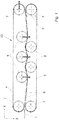
- Figure 1 shows an impregnation system or an impregnation module 13 (s. Figure 3 ), which has two tape loops 4, 5 assigned to one another.
- the first 4 and the second belt loop 5 are formed by respective endless belts which have deflection rollers 7 in their deflection regions and additionally have several further rollers 8 arranged between the respective deflection rollers 7.
- the deflection rollers over which the respective endless belts are guided, span a belt loop area 9 between the upper side and the lower side.
- the first belt loop 4 shown above has three further rollers 8 arranged between the two deflection rollers 7 and forms a surface 6, which is the same as in FIG Figure 1 is assigned second tape loop 5 shown below. That is, the lower side of the tape loop 4 and the upper side of the tape loop 5 are inclined towards each other.
- the textile fabric 1 is passed between the inclined surfaces 6 and subjected to a corresponding pressure, which is intended to ensure that the textile fabric, which consists of a pure textile fabric 3 and a matrix 2 in the form of a film or a fleece, for example.
- the deflecting rollers 7 are adjustable in the x direction, which is indicated by the horizontal thick arrow on the upper right deflecting roller 7. As a result, the tension of the endless belt within the first belt loop 4 can be changed.
- three further rollers 8 are arranged, which are spaced apart from one another which is large enough that the rollers 8 in the belt loop 4 in the belt loop area 9 of further rollers 8 which are arranged in the second belt loop 5 with a immerse yourself in a certain depth.
- the further rollers 8 of the second belt loop 5 can move into the belt loop region (not shown) of the first belt loop 4 immerse, also between the spaced apart additional rollers 8 in the second belt loop 5.
- the wrap angle that the textile fabric in the area of the mutually facing surfaces 6 when conveying over the respective further roller 8 experiences varies.
- the wrap angle guarantees an essentially uniform application of pressure to the textile fabric 1 together with the matrix 2, so that an essentially constant pressure can be exerted on the matrix 2 over a surface area, which thereby penetrates evenly into the actual textile fabric 3 and there a correspondingly causes even distribution.
- the further rollers 8 are offset in the y direction, this causes a shortening of the length of the belt loop, which is compensated for by a corresponding setting or adjustment of the deflecting rollers 7 in the x direction.
- FIG. 2 is shown how the textile fabric consisting of a material layer A, the matrix, and the material layer B, the textile layer, is applied to the further roller 8 through the wrap angle, whereby a compressive force F D is exerted on the textile fabric 1 in the area of the wrap angle is exercised.
- a corresponding belt tension is generated, which in FIG Figure 2 is represented by the tensile force Fz in the direction of the textile fabric 1.
- the corresponding application of pressure when passing through the impregnation module is transferred to the layered material system, namely the textile fabric 1, which means that the flowable material layer of the matrix 2 impregnates the porous material layer of the textile layer 3 due to the pressure acting in the direction of the thickness.
- the pressure builds up along the textile fabric 1 in the conveying direction. This enables the air to escape from the porous layer against the conveying direction.
- the impregnation module shown in principle has the advantage that, via the adjustable wrap angle, the pressure force exerted and thus the respective length of a respective further roller 8 on the textile fabric 1 to penetrate the Matrix 2 in the porous textile material layer 3, ie the textile sheet 1, can be adjusted.
- the deflecting rollers 7 and expediently also the further rollers 8 can be varied in the y-direction within the respective belt loop 4, 5.
- the deflecting rollers 7 can be adjusted at least in the x direction in order to compensate for a shortening of the length by adjusting the further rollers 8 in the y direction for the respective belt loop 4, 5.
- the deflection rollers 7 are arranged one below the other, with such an arrangement there is no need for adjustment in the y-direction, since the pressure introduced linearly into the textile fabric is to be avoided.
- the first tape loop 4 and the second tape loop 5 can have a different length.
- the deflection rollers 7 of one belt loop 4 or 5 can dip into the belt loop region 9 of the other belt loop 4 or 5.
- the deflecting rollers 7 can thus, as it were, take over the function of the further rollers 8 arranged within a respective belt loop.
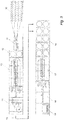
- FIG 3 shows how an impregnation system is classified as an impregnation module 13 in a complete system in the sense of a two-stage processing technology for the production of impregnated unidirectional single-layer tapes and multi-layer composite semi-finished products with a multi-axial reinforcement alignment.
- the basic structure of such an overall system has a creel 10 from which a corresponding number of threads are drawn off, which are combined in a unit downstream of creel 10, a spreading module 11, so that the widest possible spreading is achieved to achieve the lowest possible basis weight becomes.
- the spreading module 11 is followed by a processing unit 12, which has wound the matrix 2, preferably as a film or fleece, so that a flat structure 1 is created by unwinding the matrix 2, which has an actual textile layer 3 and a matrix layer 2, which when passing through the Plant are combined in such a way that the matrix 2 penetrates the porous textile layer 3.
- the system can be adjusted in such a way that the matrix material penetrates completely into the porous textile layer.
- the matrix 2 penetrates into the textile fabric from both sides of the textile layer 3. It is also possible for the matrix 2 to completely penetrate the textile layer.
- the processing unit 12 for the matrix 2 is followed by the impregnation system 13, ie the impregnation module, which is also referred to as the consolidation module.
- the basic structure of this impregnation module is that which is related to Figures 1 and 2 has already been described.
- winding is carried out in the downstream turret winder 14 with simultaneous turning of the impregnated textile fabric.
- the textile fabric 1 after its impregnation an impregnated UD tape 15, which is unwound in a tape unwinding unit 16 and fed to a laminating module 17.
- a lamination module is always used when additional layers are to be laminated onto the impregnated textile fabric, which is done with composite components which are to achieve a given property.
- a transverse cutting module 18 connected downstream of the laminating module 17, the impregnated and laminated textile fabric is cut into lengths which are placed on a pallet in the sense of a palletizing 19.
- the semi-finished products produced in this way can be brought into appropriate shapes for further use due to the use of thermoplastics for the matrix material by heating, which takes place at the place of use without a matrix 2 then having to be added under difficult operating conditions.
Abstract
Es werden eine Imprägnieranlage und ein Verfahren zum Imprägnieren eines textilen Flächengebildes für Kompositbauteile beschrieben. Dabei ist eine Matrix 2 derart auf ein textiles Flächengebilde 1 aufbringbar, dass dieses zumindest teilweise und/oder zumindest einseitig von der Matrix 2 durchdrungen ist. Für die Imprägnieranlage sind ein erstes und ein zweites als Bandschlaufe jeweils ausgebildetes Endlosband 1 vorgesehen. Zwischen der ersten 4 und der zweiten Bandschlaufe 5 ist das textile Flächengebilde 1 an den einander zugewandten Oberflächen 6 der Bandschlaufen geführt und dort imprägnierbar. Die Umlenkwalzen 7 sind in der jeweiligen Bandschlaufe 4, 5 der jeweiligen Endlosbänder an den Umlenkbereichen vorgesehen, wobei zumindest je eine Walze in Richtung der einander zugewandten Oberflächen 6 der Bandschlaufen 4,5 verstellbar sind. Durch das Verstellen der Walzen 8 in y-Richtung wird der Umschlingungswinkel und damit der auf das textile Flächengebilde beim Imprägnieren ausgeübte Druck gesteuert.An impregnation system and a method for impregnating a textile fabric for composite components are described. A matrix 2 can be applied to a flat textile structure 1 in such a way that the matrix 2 penetrates it at least partially and / or at least on one side. For the impregnation system, a first and a second endless belt 1, each designed as a belt loop, are provided. Between the first 4 and the second tape loop 5, the textile fabric 1 is guided on the mutually facing surfaces 6 of the tape loops and can be impregnated there. The deflection rollers 7 are provided in the respective belt loop 4, 5 of the respective endless belts at the deflection areas, at least one roller each being adjustable in the direction of the mutually facing surfaces 6 of the belt loops 4, 5. By adjusting the rollers 8 in the y-direction, the wrap angle and thus the pressure exerted on the textile fabric during impregnation is controlled.
Description
Die Erfindung betrifft eine Imprägnieranlage und ein Verfahren zum Imprägnieren eines textilen Flächengebildes für Kompositbauteile.The invention relates to an impregnation system and a method for impregnating a textile fabric for composite components.
Das Verfahren zum Imprägnieren eines textilen Flächengebildes für Kompositbauteile wird mittels einer Imprägnieranlage realisiert. Beim Imprägnieren von textilen Flächengebilden werden Doppelbandpressen, Kalandersysteme oder Kaschieranlagen eingesetzt, bei welchen die zu imprägnierenden Materialen über Rollensysteme mit Druckbeaufschlagung bzw. durch Einstellung eines definierten Spaltes zwischen den Rollensystemen kontinuierlich miteinander verbunden oder eben auch imprägniert werden. Dadurch, dass die Rollen in der Regel senkrecht übereinander angeordnet sind, wird bei entsprechender Druckbeaufschlagung des zu imprägnierenden Materials eine Linienpressung durch die jeweiligen Rollen ausgeübt. Nachteilig dabei ist, dass bei hohen Produktionsgeschwindigkeiten dies zu einer schlagartigen oder kurzzeitigen, unter Umständen auch relativ hohen Druckbeaufschlagung führt. Um diesen Effekt etwas abzumildern, sind steife Stahlbänder mit hoher Zugkraftausspannung verwendet worden, um auch zwischen den Rollensystemen eine gewisse Druckkraft in Dickenrichtung des zu imprägnierenden und durch die entsprechende Anlage geförderten Materials zu erhalten. Es ist üblich, dass mehrere Rollenpaare in kurzen Abständen hintereinander angeordnet sind. Bei diesen bekannten Rollenanordnungen wird eben hauptsächlich dann auf das zu verbindende Material Druck ausgeübt, wenn die Linienpressung zwischen einander gegenüberliegenden Rollen erfolgt. Dazwischen erfolgt eine weitgehende Druckentlastung.The method for impregnating a textile fabric for composite components is implemented by means of an impregnation system. When impregnating textile fabrics, double belt presses, calender systems or lamination systems are used, in which the materials to be impregnated are continuously connected or impregnated via roller systems with pressure application or by setting a defined gap between the roller systems. Because the rollers are generally arranged vertically one above the other, a line pressure is exerted by the respective rollers when the material to be impregnated is subjected to appropriate pressure. The disadvantage here is that at high production speeds this leads to a sudden or short-term, possibly also relatively high, pressure application. In order to mitigate this effect somewhat, stiff steel belts with high tensile force relaxation have been used in order to obtain a certain compressive force in the direction of the thickness of the material to be impregnated and conveyed through the corresponding system between the roller systems. It is common for several pairs of rollers to be arranged one behind the other at short intervals. In these known roller arrangements, pressure is mainly exerted on the material to be connected when the line pressure takes place between opposing rollers. In between there is extensive pressure relief.
Beim Imprägnieren werden in der Regel Materialsysteme miteinander verbunden, bei denen ein kontinuierliches Fließen eines der Materialen notwendig ist, dies ist in der Regel das Imprägniermittel, bei Kompositmaterialien auch Matrix genannt. Soll das Imprägniermittel gleichmäßig verteilt werden, muss auch eine kontinuierlich wirkende Druckbeaufschlagung realisiert werden. Insbesondere bei textilen Flächengebilden aus Verstärkungsfasern wie Glasfasern, Kohlenstofffasern oder Aramidfasern, welche mit der Matrix imprägniert werden sollen, ist dies erforderlich.During impregnation, material systems are usually connected to one another, in which a continuous flow of one of the materials is necessary, this is usually the impregnating agent, also called matrix for composite materials. If the impregnation agent is to be evenly distributed, a continuously acting pressurization must also be implemented. This is necessary in particular in the case of textile fabrics made of reinforcing fibers such as glass fibers, carbon fibers or aramid fibers, which are to be impregnated with the matrix.
In
Aus
In
Demgegenüber besteht die Aufgabe der Erfindung darin, ein Verfahren und eine Imprägnieranlage zur Realisierung des Verfahrens zum Imprägnieren eines textilen Flächengebildes für Kompositbauteile zu schaffen, bei welchem das Imprägniermittel, welches mit einem textilen Flächengebilde zu verbinden ist, während des Förderns durch die Imprägnieranlage möglichst gleichmäßig mit Druck belastet wird, damit das Imprägniermittel gleichmäßig und gut verteilt in das textile Flächengebilde eindringen kann, um so ein sogenanntes Prepreg guter Qualität zu schaffen.In contrast, the object of the invention is to create a method and an impregnation system for implementing the method for impregnating a textile fabric for composite components, in which the impregnation agent, which is to be connected to a textile fabric, is as uniform as possible during conveyance through the impregnation system Pressure is loaded so that the impregnant is evenly and well distributed in the textile fabric can penetrate in order to create a so-called prepreg of good quality.
Diese Aufgabe wird mit einer Imprägnieranlage mit den Merkmalen gemäß Anspruch 1 und mit einem Verfahren mit den Merkmalen gemäß Anspruch 13 gelöst. Zweckmäßige Weiterbildungen sind in den jeweiligen abhängigen Ansprüchen definiert.This object is achieved with an impregnation system with the features according to
Gemäß einem ersten Aspekt der Erfindung ist mittels der erfindungsgemäßen Imprägnieranlage ein textiles Flächengebilde für Kompositbauteile imprägnierbar, wobei eine Matrix derart auf das textile Flächengebilde aufbringbar ist, dass dieses zumindest teilweise und/oder zumindest einseitig von der Matrix durchdrungen ist. Die Matrix ist eine fließfähige Materialschicht, welche das in der Regel poröse textile Flächengebilde nach dem Zusammenführen der Matrix mit dem textilen Flächengebilde durchdringt. Dabei kann die Matrix das textile Flächengebilde komplett an allen Stellen und vorzugsweise im Wesentlichen gleichmäßig durchdringen. Es ist jedoch auch möglich, dass das Flächengebilde teilweise von der Matrix durchdrungen ist. Indem das textile Flächengebilde teilweise oder überall im gesamten Bereich durchdrungen ist, werden gezielt entsprechende mechanische Eigenschaften des späteren imprägnierten textilen Flächengebildes, welches auch als Prepreg bezeichnet wird, erzeugt. Je nach Anwendungsfall kann die Matrix das textile Flächengebilde einseitig durchdringen. Darunter ist zu verstehen, dass es auf einer Seite des textilen Flächengebildes aufgebracht worden ist und innerhalb der Imprägnieranlage von einer Seite her das textile Flächengebilde durchdringt. Vorzugsweise ist es auch möglich, dass die Matrix auf beide Seiten des textilen Flächengebildes aufgebracht wird und ein Imprägnieren desselben dann von beiden Seiten erfolgt.According to a first aspect of the invention, a textile fabric for composite components can be impregnated by means of the impregnation system according to the invention, a matrix being able to be applied to the textile fabric in such a way that it is at least partially and / or at least on one side penetrated by the matrix. The matrix is a flowable material layer which penetrates the generally porous textile fabric after the matrix has been brought together with the textile fabric. The matrix can penetrate the textile fabric completely at all points and preferably essentially uniformly. However, it is also possible for the matrix to partially penetrate the sheet-like structure. Since the textile fabric is penetrated partially or everywhere in the entire area, corresponding mechanical properties of the later impregnated textile fabric, which is also referred to as prepreg, are created in a targeted manner. Depending on the application, the matrix can penetrate the textile fabric on one side. This is to be understood as meaning that it has been applied to one side of the textile fabric and penetrates the textile fabric from one side within the impregnation system. It is preferably also possible for the matrix to be applied to both sides of the flat textile structure and for it to be impregnated from both sides.
Gemäß der Erfindung weist die Imprägnieranlage ein erstes und ein zweites Endlosband auf, welches jeweils als Bandschlaufe ausgebildet ist. Innerhalb jeder Bandschlaufe sind Walzen angeordnet, über welche das Endlosband läuft und sozusagen die innerhalb der Bandschlaufe befindlichen Walzen umschließt. Die zwei Bandschlaufen, welche einander zugewandte Flächen haben und innerhalb Walzen umschließen, führen zwischen den zueinander zugewandten Oberflächen das textile Flächengebilde, wobei während des Durchlaufens des textilen Flächengebildes an der Kontaktstelle zwischen den beiden Bandschlaufen das textile Flächengebilde imprägnierbar ist. Die Bandschlaufen weisen Umlenkwalzen an ihren jeweiligen Umlenkbereichen auf, von den zumindest je eine Walze in Richtung der einander zugewandten Oberflächen der Bandschlaufen verstellbar ist. Dies stellt die y-Richtung dar. Indem die Umlenkwalzen in y-Richtung versetzbar sind, wird ein über die entsprechende, durch den Kontakt der Bandschlaufen bestimmte Druckfläche Druck auf die Matrix, d. h. die fließfähige Materialschicht, ausgeübt, so dass diese die poröse Materialschicht in Form des textilen Flächengebildes imprägniert, d. h. durchdringt.According to the invention, the impregnation system has a first and a second endless belt, each of which is designed as a belt loop. Within each belt loop, rollers are arranged over which the endless belt runs and, so to speak, encloses the rollers located within the belt loop. The two belt loops, which have mutually facing surfaces and enclose inside rollers, guide the textile fabric between the mutually facing surfaces, with the textile fabric being impregnable at the contact point between the two belt loops as the fabric passes through. The belt loops have deflection rollers at their respective deflection areas, of which at least one roller is adjustable in the direction of the surfaces of the belt loops facing one another. This represents the y-direction. Since the deflection rollers can be displaced in the y-direction, a pressure is exerted on the matrix, ie the flowable material layer, via the corresponding pressure surface determined by the contact of the belt loops. so that it impregnates, ie penetrates, the porous material layer in the form of the textile fabric.
Eine Verstellung der Umlenkwalzen in y-Richtung führt dazu, dass die zugewandten Bandschlaufen an ihrer Berührungsstelle einen unterschiedlichen Druck entwickeln können, mit welchem die Matrix in das textile Flächengebilde hineingedrückt und dieses somit imprägniert werden kann.Adjusting the deflecting rollers in the y-direction means that the facing tape loops can develop a different pressure at their point of contact, with which the matrix can be pressed into the textile fabric and this can thus be impregnated.
Vorzugsweise ist es auch möglich, dass die Umlenkwalzen auch in x-Richtung verschiebbar bzw. verstellbar sind, so dass die Endlosbänder der jeweiligen Bandschlaufe mehr oder weniger stark gespannt werden können, wodurch auch die Druckverhältnisse des zu imprägnierenden textilen Flächengebildes beim Durchlaufen zwischen den Berührungsstellen der beiden einander zugewandten Bandschlaufen einstellbar sind.It is preferably also possible for the deflection rollers to be displaceable or adjustable in the x direction, so that the endless belts of the respective belt loop can be stretched more or less strongly, which also reduces the pressure conditions of the textile fabric to be impregnated when passing between the contact points of the both facing tape loops are adjustable.
Vorzugsweise ist innerhalb zumindest einer der beiden Bandschlaufen eine weitere Walze angeordnet, welche in Richtung der einander zugewandten Oberflächen der beiden gegenüberliegenden Bandschlaufen verstellbar ist. Die weitere Walze ist also in y-Richtung verstellbar. Dabei kann diese weitere Walze allein verstellbar sein. Es ist jedoch auch möglich, dass sowohl die weitere Walze als auch die Umlenkwalzen unabhängig voneinander in y-Richtung verschiebbar und soweit einstellbar sind, dass die Walzen bzgl. ihrer Rotationsachsen entweder in einer Ebene liegen oder so weit auseinander liegen, dass die Walzen aufgrund ihres sozusagen Eintauchens zwischen die Walzen der gegenüberliegenden Bandschlaufe nicht mehr unmittelbar in Kontakt mit der anderen Seite der Bandschlaufe liegt. Nicht mehr in Kontakt mit der anderen Seite der Bandschlaufe bedeutet, dass der außen laufende Teil des Endlosbandes, welcher zurückgeführt wird, um am Eintritt der Imprägnieranlage erneut mit dem zu imprägnierenden Flächengebilde in Kontakt gelangt. Während des Zurücklaufens des Endlosbandes an der Au-βenseite der Bandschlaufe, erfährt dieser Außenbereich trotz der Biegeschlaffheit des Endlosbandes der jeweiligen Bandschlaufe keine Auslenkung. Die Biegeschlaffheit hat den Vorteil, dass das als umlaufendes Warentransportsystem ausgebildete Walzensystem eine Einstellung der Zustellung der Walzen zueinander und damit der Umschlingungslänge des biegeschlaffen Endlosbandes der jeweiligen Bandschlaufe um eine jeweilige Walze ermöglicht. Dieses Warentransportsystem besteht also aus mindestens zwei Bandschlaufen in der Art von Förderbändern, zwischen welchen ein zu imprägnierendes Materialsystem transportiert und bearbeitet wird. Die Temperaturumgebung für das zu imprägnierende textile Flächengebilde kann in einem Bereich zwischen Raumtemperatur bzw. Umgebungstemperatur und 300°C eingestellt werden.A further roller is preferably arranged within at least one of the two belt loops, which roller is adjustable in the direction of the mutually facing surfaces of the two opposite belt loops. The further roller is therefore adjustable in the y direction. This further roller can be adjusted on its own. However, it is also possible that both the further roller and the deflection rollers can be displaced independently of one another in the y-direction and can be adjusted to such an extent that the rollers with respect to their axes of rotation either lie in one plane or are so far apart that the rollers due to their so to speak, immersion between the rollers of the opposite belt loop is no longer in direct contact with the other side of the belt loop. No longer in contact with the other side of the belt loop means that the outer part of the endless belt, which is fed back, comes into contact again with the sheet-like structure to be impregnated at the entrance to the impregnation system. During the return of the endless belt on the outside of the belt loop, this outer area does not experience any deflection despite the flexural slackness of the endless belt of the respective belt loop. The flexural slackness has the advantage that the roller system designed as a revolving goods transport system enables adjustment of the infeed of the rollers to one another and thus the wrap length of the flexible endless belt of the respective belt loop around a respective roller. This goods transport system therefore consists of at least two belt loops in the manner of conveyor belts, between which a material system to be impregnated is transported and processed. The temperature environment for the textile fabric to be impregnated can be set in a range between room temperature or ambient temperature and 300 ° C.
Zwischen den zwei Bandschlaufen wird das zu imprägnierende Materialsystem mitgeführt. Das Materialsystem weist mehrere Schichten unterschiedlichen Materials auf, von denen mindestens eine Schicht aus einem porösen Material B, dem eigentlichen textilen Flächengebilde, sowie mindestens einer Schicht aus einem Material A besteht, der Matrix, welche in der angegebenen Temperaturumgebung einen fließfähigen Zustand besitzt, wobei die dynamische Viskosität zwischen 10 und 1000 Pa*s, vorzugsweise 50 und 500 Pa*s, liegt. Das Material A besteht vorzugsweise aus thermoplastischen Kunststoffen, insbesondere Polyolefinen oder Polyamiden, welche in der angegebenen Temperaturumgebung einen schmelzflüssigen Aggregatzustand aufweisen und ein viskoelastisches Materialverhalten besitzen.The material system to be impregnated is carried along between the two belt loops. The material system has several layers of different material, of which at least one layer consists of a porous material B, the actual textile fabric, and at least one layer consists of a material A, the matrix, which has a flowable state in the specified temperature environment, the dynamic viscosity between 10 and 1000 Pa * s, preferably 50 and 500 Pa * s. The material A preferably consists of thermoplastics, in particular polyolefins or polyamides, which in the specified temperature environment have a molten aggregate state and have a viscoelastic material behavior.
Zusammenfassend ist also festzustellen, dass durch eine gezielte Zustellung der Walzen in y-Richtung zueinander ein definierter Umschlingungswinkel des zu imprägnierenden textilen Flächengebildes um die Walzen einstellbar ist. Durch die Zustellung einer Walze, insbesondere der Umlenkwalze, in x-Richtung kann die Zugkraft im Endlosband in der jeweiligen Bandschlaufe gezielt eingestellt werden. Die erfindungsgemäße Imprägnieranlage, die auch ein Warentransportsystem darstellt, weist den für die Qualität und Zuverlässigkeit und Isotropie der Eigenschaften des mit Matrix getränkten textilen Flächengebildes in Form eines Prepregs den Vorteil auf, dass das zu imprägnierende Materialsystem nicht nur kontinuierlich an den Umlenkwalzen einer Druckbeaufschlagung ausgesetzt wird, sondern diese Druckbeaufschlagung erfolgt stets senkrecht zur Walzenoberfläche in Dickenrichtung des Materialsystems, welches imprägniert wird. Diese Druckbeaufschlagung wirkt über einen definierten Zeitraum, welcher sich aus der Transportgeschwindigkeit des zu imprägnierenden textilen Flächengebildes und dem Umfangsbogen ergibt, welcher durch den Umschlingungswinkel definiert ist, welchen das zu imprägnierende textile Flächengebilde durchfährt. Durch die gleichmäßige Druckbeaufschlagung in der Imprägnieranlage wird dieser Druck auf das vorzugsweise schichtweise aufgebaute Materialsystem übertragen. Diese Druckübertragung in der gleichmäßigen Art, wie es durch die Erfindung gewährleistet ist, führt dazu, dass die fließfähige Materialschicht A die poröse Materialschicht B in Form des textilen Flächengebildes aufgrund des wirkenden gleichmäßigen Druckes in Dickenrichtung gleichmäßig imprägniert.In summary, it can be stated that a defined angle of wrap of the textile fabric to be impregnated around the rollers can be set by a targeted feed of the rollers in the y-direction. By advancing a roller, in particular the deflection roller, in the x direction, the tensile force in the endless belt can be set in a targeted manner in the respective belt loop. The impregnation system according to the invention, which also represents a goods transport system, has the advantage for the quality, reliability and isotropy of the properties of the fabric soaked with matrix in the form of a prepreg that the material system to be impregnated is not only continuously subjected to pressure at the deflection rollers , but this application of pressure always takes place perpendicular to the roll surface in the direction of the thickness of the material system that is being impregnated. This application of pressure acts over a defined period of time, which results from the transport speed of the textile fabric to be impregnated and the circumferential arc, which is defined by the wrap angle which the textile fabric to be impregnated traverses. Through the uniform application of pressure in the impregnation system, this pressure is transferred to the material system, which is preferably built up in layers. This pressure transfer in the uniform manner, as it is ensured by the invention, leads to the fact that the flowable material layer A uniformly impregnates the porous material layer B in the form of the textile fabric due to the uniform pressure acting in the thickness direction.
Ein weiterer Vorteil der Erfindung besteht darin, dass aufgrund der Zustellung der Walzen in y-Richtung ein Umschlingungswinkel individuell eingestellt werden kann. Der in Dickenrichtung wirkende Druck baut sich dabei entlang der Bandschlaufe in Transportrichtung auf. Dadurch kann Luft in der porösen Schicht entgegen der Transportrichtung entweichen.Another advantage of the invention is that, due to the infeed of the rollers in the y direction, a wrap angle can be set individually. The pressure acting in the thickness direction builds up along the belt loop in the transport direction. This allows air to escape in the porous layer against the direction of transport.
Vorzugsweise weist zumindest eine der beiden Bandschlaufen mehrere weitere Walzen auf, welche zwischen den Umlenkwalzen angeordnet sind und zumindest mit einer Richtungskomponente bzgl. der y-Richtung senkrecht zu den einander zugewandten Oberflächen der beiden Bandschlaufen in den Bandschlaufenbereich der anderen Bandschlaufe eintauchbar verstellbar ist. Relativ große Abstände von Walzen innerhalb des oberen Bandschlaufensystems ermöglichen dort ein relativ tiefes Eintauchen von weiteren Walzen des unteren Bandschlaufensystems.At least one of the two belt loops preferably has a plurality of further rollers which are arranged between the deflecting rollers and which have at least one directional component with respect to the y-direction perpendicular to the mutually facing surfaces of the two tape loops in the tape loop area of the other tape loop is adjustable. Relatively large distances between rollers within the upper belt loop system enable further rollers of the lower belt loop system to be immersed relatively deeply there.
Weiter vorzugsweise sind die verstellbaren Umlenkwalzen unabhängig voneinander verstellbar. Damit kann an beliebigen Orten und zu beliebigen Zeiten der Umschlingungswinkel und damit der auf das zu imprägnierende textile Flächengebilde ausgeübte Druck variiert werden. Es ist dadurch auch möglich, dass längs der Förderrichtung des textilen Flächengebildes durch die Imprägnieranlage der Druck und damit die Durchdringungstiefe der Matrix innerhalb des textilen Flächengebildes anwendungsspezifisch variiert werden kann.The adjustable deflecting rollers are also preferably adjustable independently of one another. In this way, the wrap angle and thus the pressure exerted on the textile fabric to be impregnated can be varied at any location and at any time. It is thereby also possible that the pressure and thus the depth of penetration of the matrix within the textile fabric can be varied in an application-specific manner along the conveying direction of the textile fabric through the impregnation system.
Vorzugsweise ist die Verstellung der zumindest einen weiteren Walze in y-Richtung beim Eintauchen in die andere Bandschlaufe bzgl. ihrer Eintauchtiefe so regelbar, dass das textile Flächengebilde einen veränderlichen Umschlingungswinkel um die weitere Walze aufweist. Durch Verstellung der Umlenkwalzen ebenfalls in y-Richtung, d. h. in Richtung der einander zugewandten Oberflächen der Endlosbänder, ist somit der Anpressdruck des textilen Flächengebildes an der weiteren Walze auf das textile Flächengebilde regelbar. Die Regelbarkeit des Anpressdruckes hat den Vorteil, dass für unterschiedliche Materialen, für unterschiedliche textile Flächengebilde und natürlich auch für unterschiedliche Matrixmaterialen der für die Imprägnierung bzw. Durchimprägnierung des textilen Flächengebildes erforderliche oder optimale Anpressdruck im Sinne des Erreichens vorgegebener Imprägnierungsgrade regelbar ist.The adjustment of the at least one further roller in the y-direction when dipping into the other belt loop with regard to its immersion depth can preferably be regulated so that the textile fabric has a variable wrap angle around the further roller. By adjusting the deflection rollers also in the y-direction, i. H. in the direction of the surfaces of the endless belts facing one another, the contact pressure of the textile fabric on the further roller on the textile fabric can be regulated. The controllability of the contact pressure has the advantage that for different materials, for different textile fabrics and, of course, for different matrix materials, the required or optimal contact pressure for the impregnation or thorough impregnation of the textile fabric can be regulated in order to achieve a given degree of impregnation.
Gemäß einer weiteren bevorzugten Ausführungsform sind die weiteren Walzen an ihrer Außenkontur längs ihrer Drehachse ballenförmig oder konkav gekrümmt. Die Abweichung von einer zylindrischen Form der Walzen kann aus technologischen oder physikalischen Gegebenheiten der textilen Flächengebilde im Zusammenhang mit der gewünschten Imprägnierungstiefe vorteilhaft sein.According to a further preferred embodiment, the further rollers are curved in a ball-shaped or concave manner on their outer contour along their axis of rotation. The deviation from a cylindrical shape of the rollers can be advantageous due to technological or physical circumstances of the textile fabric in connection with the desired impregnation depth.
Zusätzlich zu einer entsprechenden Gestaltung der äußeren Form, gegebenenfalls abweichend von einer zylindrischen Form, kann vorgesehen sein, dass die weitere Walze bzw. die weiteren Walzen in ihrer Längsrichtung bewegbar, insbesondere vibrierbar sind. Die zusätzliche Bewegungskomponente der weiteren Walzen in ihrer Längsrichtung kann dazu beitragen, dass eine bessere Imprägnierung, d. h. Durchdringung, des textilen Flächengebildes erreicht wird. Das textile Flächengebilde stellt ein poröses Material dar, welches beim Imprägnieren von der Matrix durchdrungen wird, indem die Zwischenräume zwischen den einzelnen Fasern durch die Matrix aufgefüllt werden. Durch eine Vibration der weiteren Walze kann das Durchdringen des textilen Flächengebildes mit der Matrix verbessert werden, so dass ein sehr hoher Imprägnierungsgrad erreicht werden kann.In addition to a corresponding design of the outer shape, possibly deviating from a cylindrical shape, it can be provided that the further roller or the further rollers can be moved, in particular vibrated, in their longitudinal direction. The additional movement component of the further rollers in their longitudinal direction can contribute to better impregnation, ie penetration, of the textile fabric being achieved. The textile fabric is a porous material which is penetrated by the matrix during impregnation, in that the interstices between the individual fibers are filled by the matrix. A vibration of the other roller can penetrate the textile Flat structure can be improved with the matrix, so that a very high degree of impregnation can be achieved.
Um die Fließfähigkeit der Matrix für das Imprägnieren des textilen Flächengebildes zu erhöhen, kann gemäß einem weiteren Ausführungsbeispiel vorgesehen sein, dass zumindest eine weitere Walze wie auch sämtliche weiteren Walzen temperierbar sind, so dass über die Erhöhung der Temperatur der Matrix deren Viskosität erniedrigt werden kann, um die Fließeigenschaften im porösen textilen Flächengebilde im Sinne eines Durchdringens zu verbessern.In order to increase the flowability of the matrix for the impregnation of the textile fabric, it can be provided according to a further embodiment that at least one further roller as well as all further rollers can be tempered so that the viscosity of the matrix can be reduced by increasing the temperature in order to improve the flow properties in the porous textile fabric in terms of penetration.
Damit das textile Flächengebilde während des Imprägnierens mit der Matrix schonend behandelt wird, d. h. schonend durch die Imprägnieranlage mittels der Endlosbänder gefördert und dabei imprägniert wird, sind die Endlosbänder vorzugsweise temperaturstabil, reibungsarm und antihaftbeschichtet ausgebildet. Insbesondere die Antihaftbeschichtung gewährleistet, dass das in der Imprägnieranlage imprägnierte textile Flächengebilde an den Endlosbändern beim Verlassen der Imprägnieranlage nicht haftet und daher leicht abgeführt, und als Prepreg entsprechend bis zur Endanwendung gelagert werden kann.So that the textile fabric is treated gently during impregnation with the matrix, i. H. is gently conveyed through the impregnation system by means of the endless belts and thereby impregnated, the endless belts are preferably designed to be temperature-stable, low-friction and non-stick coated. In particular, the non-stick coating ensures that the textile fabric impregnated in the impregnation system does not adhere to the endless belts when it leaves the impregnation system and can therefore be easily removed and stored as a prepreg until it is used.
Vorzugsweise ist das textile Flächengebilde eine Fasern aufweisende unidirektionale Lage oder ein Multiaxialgelege. Es ist jedoch auch möglich, dass das textile Flächengebilde ein Vlies ist oder ein Gewebe.The flat textile structure is preferably a unidirectional layer comprising fibers or a multiaxial layer. However, it is also possible that the textile fabric is a fleece or a woven fabric.
Vorzugsweise ist die Matrix eine Polymermatrix und weiter vorzugsweise eine thermoplastische Matrix. Der Vorteil der Verwendung einer thermoplastischen Matrix besteht darin, dass durch Temperaturerhöhung die Viskosität des Matrixmaterials herabgesetzt werden kann, so dass eine entsprechend der Viskosität des Thermoplastmaterials gewünschte Viskosität über eine Temperaturregelung einstellbar ist. Damit kann für unterschiedliche Materialen und unterschiedliche Fertigungsbedingungen die Durchdringung der Matrix in das textile Flächengebilde gesteuert werden. Vorzugsweise ist das Ausgangsmaterial der thermoplastischen Matrix, welches der Imprägnieranlage zugeführt wird, ein biegeschlaffes Flächengebilde in Form einer Folie oder eines Vlieses.The matrix is preferably a polymer matrix and more preferably a thermoplastic matrix. The advantage of using a thermoplastic matrix is that the viscosity of the matrix material can be reduced by increasing the temperature, so that a desired viscosity corresponding to the viscosity of the thermoplastic material can be set via temperature control. In this way, the penetration of the matrix into the textile fabric can be controlled for different materials and different manufacturing conditions. The starting material of the thermoplastic matrix, which is fed to the impregnation system, is preferably a pliable flat structure in the form of a film or a fleece.
Gemäß einem zweiten Aspekt der Erfindung wird ein Verfahren zum Imprägnieren eines textilen Flächengebildes für Kompositbauteile bereitgestellt, welches mit einer Matrix bzw. einem Matrixmaterial getränkt wird. Durch das Tränken des textilen Flächengebildes mit einem Matrixmaterial wird das textile Flächengebilde imprägniert und bildet ein sogenanntes Prepreg. Das ist insbesondere von Bedeutung für thermoplastische Matrixmaterialen in der Hinsicht, dass die Prepregs relativ steif sind und gut transportierbar sind, für eine praktische Anwendung aber häufig einen entsprechenden Grad an Flexibilität und Drapierfähigkeit aufweisen müssen, was erreicht werden kann, indem das Thermoplastmaterial und damit das mit dem Thermoplastmaterial imprägnierte bzw. getränkte textile Flächengebilde erwärmt wird, wodurch das Prepreg in eine gewünschte Form bei dreidimensionalen Anwendungen gebracht werden kann. Zum Imprägnieren wird das textile Flächengebilde zwischen zwei jeweils aus einem Endlosband gebildeten über Umlenkwalzen laufende Bandschlaufen geführt. Der Anpressdruck, mit welchem die Umlenkwalzen, nachdem das textile Flächengebilde mit dem Thermoplastmaterial zusammengebracht wird, wird über die Spannung der Endlosbänder und durch Verstellung der Walzen in Richtung der zueinander zugewandten Oberflächen der Bandschlaufen (d. h. in y-Richtung) sowie durch Variation des Umschlingungswinkels der Endlosbänder an den Walzen geregelt. Dabei werden die Walzen in y-Richtung verschoben, was vor allen Dingen auch dann so durchgeführt wird, wenn das textile Flächengebilde zumindest teilweise mit der Matrix, insbesondere beidseitig, durchtränkt wird, so dass das textile Flächengebilde vollständig durchimprägniert ist, wenn in den Bandschlaufen innenliegende weitere Walzen vorgesehen sind, welche durch ihre Verlagerung in y-Richtung die Walzen in die gegenüberliegende Bandschlaufe eintauchen. Bei einem höheren Grad der Umschlingung der jeweiligen Walze mit dem Endlosband wird der Druck größer, welcher auf das textile Flächengebilde zusammen mit dem zum Imprägnieren verwendeten Matrixmaterial beim Durchlaufen der Imprägnieranlage wirkt.According to a second aspect of the invention, a method for impregnating a textile fabric for composite components is provided, which is impregnated with a matrix or a matrix material. By impregnating the textile fabric with a matrix material, the textile fabric is impregnated and forms a so-called prepreg. This is particularly important for thermoplastic matrix materials in that the prepregs are relatively stiff and easy to transport, but are often used in practice must have a corresponding degree of flexibility and drapability, which can be achieved by heating the thermoplastic material and thus the textile fabric impregnated or soaked with the thermoplastic material, whereby the prepreg can be brought into a desired shape for three-dimensional applications. For the impregnation, the textile fabric is guided between two belt loops, each formed from an endless belt, running over deflection rollers. The contact pressure with which the deflection rollers, after the textile fabric is brought together with the thermoplastic material, is determined by the tension of the endless belts and by adjusting the rollers in the direction of the surfaces of the belt loops facing each other (i.e. in the y-direction) as well as by varying the wrap angle of the Controlled endless belts on the rollers. The rollers are shifted in the y-direction, which is also done when the textile fabric is at least partially soaked with the matrix, especially on both sides, so that the textile fabric is completely impregnated when it is inside the tape loops further rollers are provided which, as a result of their displacement in the y direction, dip the rollers into the opposite belt loop. With a higher degree of wrapping of the respective roller with the endless belt, the pressure that acts on the textile fabric together with the matrix material used for impregnation when passing through the impregnation system increases.
Vorzugsweise wird das textile Flächengebilde vollständig durchimprägniert.The textile fabric is preferably completely impregnated.
Und schließlich ist das textile Flächengebilde vorzugsweise eine unidirektionale Lage oder ein Multiaxialgelege, welche bzw. welches mit einer Matrix, insbesondere einer thermoplastischen Matrix, imprägniert wird.And finally, the textile fabric is preferably a unidirectional layer or a multiaxial lay-up which is impregnated with a matrix, in particular a thermoplastic matrix.
Vorzugsweise ist für die Imprägnieranlage bzw. ein Imprägniermodul ein nachgeschaltetes Messsystem vorgesehen, mittels welchem eine kontinuierliche und zerstörungsfreie Messung der Breite und der Dicke des die Imprägnieranlage verlassenden Materials erfolgt. Dabei wird die Dicke des Materials über seine gesamte Breite gemessen. Die mittlere Dicke wird bei der ebenfalls gemessenen Breite mit einem Referenzwert, der Kompaktierungsdicke, verglichen. Die Kompaktierungsdicke ergibt sich aus den gegebenen Eingangsgrößen der verwendeten Materialien wie beispielsweise Flächengewicht, Dicke, Dichte, tex-Zahl und stellt einen theoretisch erreichbaren Kennwert dar. Die Abweichung der gemessenen mittleren Dicke von der theoretischen Kompaktierungsdicke in Prozent ergibt den Porenanteil und damit den Imprägniergrad.A downstream measuring system is preferably provided for the impregnation system or an impregnation module, by means of which a continuous and non-destructive measurement of the width and the thickness of the material leaving the impregnation system takes place. The thickness of the material is measured over its entire width. The mean thickness of the width, which is also measured, is compared with a reference value, the compaction thickness. The compaction thickness results from the given input variables of the materials used, such as weight per unit area, thickness, density, tex number and represents a theoretically achievable characteristic value. The deviation of the measured average thickness from the theoretical compaction thickness in percent gives the pore proportion and thus the degree of impregnation.
Weitere Vorteile, Anwendungsmöglichkeiten und Details der erfindungsgemäßen Imprägnieranlage werden nun anhand der nachfolgenden Zeichnung detailliert erläutert. In der Zeichnung zeigen:
Figur 1- eine Imprägnieranlage bzw. ein Imprägniermodul mit zwei einander zugeordneten Bandschlaufen mit jeweiligen Umlenkwalzen und weiteren Walzen;
Figur 2- eine weitere Walze innerhalb einer Bandschlaufe mit Darstellung des Umschlingungswinkels durch das textile Flächengebilde; und
Figur 3- eine aus verschiedenen Modulen aufgebaute Anlage zur Herstellung imprägnierter unidirektionaler einlagiger Tapes und mehrlagiger Verbundhalbzeuge mit multiaxialer Verstärkungsausrichtung mit Imprägniermodul.
- Figure 1
- an impregnation system or an impregnation module with two associated belt loops with respective deflecting rollers and further rollers;
- Figure 2
- another roller within a belt loop showing the angle of wrap through the textile fabric; and
- Figure 3
- a system built up from different modules for the production of impregnated unidirectional single-layer tapes and multi-layer composite semi-finished products with multi-axial reinforcement alignment with impregnation module.
Die Umlenkwalzen, über welche die jeweiligen Endlosbänder geführt sind, spannen zwischen der Oberseite und der Unterseite einen Bandschlaufenbereich 9 auf. Die in
Wenn die weiteren Walzen 8 in y-Richtung versetzt werden, so bewirkt dies eine Verkürzung der Länge der Bandschlaufe, was durch eine entsprechende Einstellung bzw. Justierung der Umlenkwalzen 7 in x-Richtung kompensiert wird. Es ist jedoch auch denkbar, bei einer Verstellung der weiteren Walzen 8 in y-Richtung zum jeweiligen Eintauchen in den Bandschlaufenbereich 9 der jeweils anderen Bandschlaufe 4 bzw. 5 die Umlenkwalzen 7 nicht in x-Richtung zu verstellen, so dass sich dadurch die Bandspannung in der jeweiligen Bandschlaufe erhöht, wodurch durch die weitere Walze 8 der auf das textile Flächengebilde 1 zusammen mit der Matrix 2 im Bereich des Umschlingungswinkels sich ausbildende Druck erhöht werden kann.If the
In
Das in den
In
Der Abwicklungseinheit 12 für die Matrix 2 schließt sich die Imprägnieranlage 13, d. h. das Imprägniermodul an, welches auch als Konsolidiermodul bezeichnet wird. Der Grundaufbau dieses Imprägniermoduls ist der, welcher bzgl. der
- 11
- textiles Flächengebildetextile fabric
- 22
- Materialschicht A / MatrixMaterial layer A / matrix
- 33
- Materialschicht B / textile Schicht / eigentliches textiles FlächengebildeMaterial layer B / textile layer / actual textile fabric
- 44th
- erste Bandschlaufe / Endlosbandfirst belt loop / endless belt
- 55
- zweite Bandschlaufe / Endlosbandsecond belt loop / endless belt
- 66th
- einander zugewandte Oberflächenfacing surfaces
- 77th
- UmlenkwalzeDeflection roller
- 88th
- weitere Walzeanother roller
- 99
- BandschlaufenbereichTape loop area
- 1010
- SpulengatterCreel
- 1111
- SpreizmodulExpansion module
- 1212
- Abwicklung Matrix (Folie, Vlies)Processing matrix (foil, fleece)
- 1313
- Imprägniermodul / KonsolidiermodulImpregnation module / consolidation module
- 1414th
- WendewicklerTurret winder
- 1515th
- UD-TapeUD tape
- 1616
- Tape-AbwicklungTape handling
- 1717th
- LaminiermodulLamination module
- 1818th
- QuerschneidmodulCross cutting module
- 1919th
- PalettierungPalletizing
Claims (16)
ein erstes und ein zweites als Bandschlaufe (4, 5) ausgebildetes Endlosband vorgesehen ist, zwischen denen an ihren einander zugewandten Oberflächen (6) das textile Flächengebilde (1) geführt und imprägnierbar ist und welche Umlenkwalzen (7) an ihren jeweiligen Umlenkbereichen aufweisen, von denen zumindest je eine Walze in Richtung der einander zugewandten Oberflächen (6) der Bandschlaufen verstellbar sind.Impregnation system for impregnating a textile fabric (1) for composite components, by means of which a matrix (2) can be applied to the textile fabric (1) in such a way that it is at least partially and / or at least on one side penetrated by the matrix (2), characterized that
a first and a second endless belt designed as a belt loop (4, 5) is provided, between which the flat textile structure (1) is guided and impregnable on their mutually facing surfaces (6) and which have deflection rollers (7) at their respective deflection areas of at least one roller each in the direction of the facing surfaces (6) of the belt loops.
Priority Applications (3)
| Application Number | Priority Date | Filing Date | Title |
|---|---|---|---|
| EP19161304.1A EP3705251B1 (en) | 2019-03-07 | 2019-03-07 | Impregnation plant and method for impregnating a textile sheet material for composite components |
| US16/807,925 US11453976B2 (en) | 2019-03-07 | 2020-03-03 | Impregnation system and method for impregnating a textile fabric for composite components |
| CN202010149323.2A CN111663265B (en) | 2019-03-07 | 2020-03-04 | Impregnating device and method for impregnating textile fabric for composite components |
Applications Claiming Priority (1)
| Application Number | Priority Date | Filing Date | Title |
|---|---|---|---|
| EP19161304.1A EP3705251B1 (en) | 2019-03-07 | 2019-03-07 | Impregnation plant and method for impregnating a textile sheet material for composite components |
Publications (2)
| Publication Number | Publication Date |
|---|---|
| EP3705251A1 true EP3705251A1 (en) | 2020-09-09 |
| EP3705251B1 EP3705251B1 (en) | 2023-05-03 |
Family
ID=65724267
Family Applications (1)
| Application Number | Title | Priority Date | Filing Date |
|---|---|---|---|
| EP19161304.1A Active EP3705251B1 (en) | 2019-03-07 | 2019-03-07 | Impregnation plant and method for impregnating a textile sheet material for composite components |
Country Status (3)
| Country | Link |
|---|---|
| US (1) | US11453976B2 (en) |
| EP (1) | EP3705251B1 (en) |
| CN (1) | CN111663265B (en) |
Families Citing this family (1)
| Publication number | Priority date | Publication date | Assignee | Title |
|---|---|---|---|---|
| CN117229563A (en) * | 2023-09-26 | 2023-12-15 | 东莞市越辉新材料科技有限公司 | Production process and equipment for silicone rubber sponge material |
Citations (6)
| Publication number | Priority date | Publication date | Assignee | Title |
|---|---|---|---|---|
| DE2856506A1 (en) * | 1978-05-18 | 1979-11-29 | Owens Corning Fiberglass Corp | METHOD AND DEVICE FOR MANUFACTURING A REINFORCED MOLDING COMPOSITE IN A RAIL SHAPE |
| EP0013548A1 (en) | 1979-01-04 | 1980-07-23 | VOEST-ALPINE Aktiengesellschaft | Apparatus for dewatering water-containing substances |
| JPH05228933A (en) * | 1992-02-24 | 1993-09-07 | Yokohama Rubber Co Ltd:The | Liquid impregnation device |
| DE60003766T2 (en) | 1999-10-20 | 2004-06-03 | Saint-Gobain Vetrotex France S.A. | Method and device for producing a composite tape formed from reinforcing fibers and thermoplastic material |
| DE102009046670A1 (en) * | 2009-11-12 | 2011-05-19 | Dieffenbacher Gmbh + Co. Kg | Plant for the production of fiber-reinforced molded parts and method for operating a plant for the production of fiber-reinforced molded parts |
| US20160271860A1 (en) | 2014-07-01 | 2016-09-22 | Teijin Limited | Production Method of Fiber-Reinforced Plastic |
Family Cites Families (4)
| Publication number | Priority date | Publication date | Assignee | Title |
|---|---|---|---|---|
| US4219524A (en) * | 1979-01-10 | 1980-08-26 | Owens-Corning Fiberglas Corporation | Method and apparatus for producing sheet molding compound |
| US5201979A (en) * | 1987-05-08 | 1993-04-13 | Research Association For New Technology Development Of High Performance Polymer | Method of manufacturing a sheet-prepreg reinforced with fibers |
| FR2894993A1 (en) * | 2005-12-19 | 2007-06-22 | Rhodia Recherches & Tech | NEW METHOD FOR IMPREGNATING A TEXTILE SURFACE |
| CN109267269B (en) * | 2018-12-03 | 2021-05-04 | 嵊州市诚宇工程建设有限公司 | Device for padding textile fabric |
-
2019
- 2019-03-07 EP EP19161304.1A patent/EP3705251B1/en active Active
-
2020
- 2020-03-03 US US16/807,925 patent/US11453976B2/en active Active
- 2020-03-04 CN CN202010149323.2A patent/CN111663265B/en active Active
Patent Citations (6)
| Publication number | Priority date | Publication date | Assignee | Title |
|---|---|---|---|---|
| DE2856506A1 (en) * | 1978-05-18 | 1979-11-29 | Owens Corning Fiberglass Corp | METHOD AND DEVICE FOR MANUFACTURING A REINFORCED MOLDING COMPOSITE IN A RAIL SHAPE |
| EP0013548A1 (en) | 1979-01-04 | 1980-07-23 | VOEST-ALPINE Aktiengesellschaft | Apparatus for dewatering water-containing substances |
| JPH05228933A (en) * | 1992-02-24 | 1993-09-07 | Yokohama Rubber Co Ltd:The | Liquid impregnation device |
| DE60003766T2 (en) | 1999-10-20 | 2004-06-03 | Saint-Gobain Vetrotex France S.A. | Method and device for producing a composite tape formed from reinforcing fibers and thermoplastic material |
| DE102009046670A1 (en) * | 2009-11-12 | 2011-05-19 | Dieffenbacher Gmbh + Co. Kg | Plant for the production of fiber-reinforced molded parts and method for operating a plant for the production of fiber-reinforced molded parts |
| US20160271860A1 (en) | 2014-07-01 | 2016-09-22 | Teijin Limited | Production Method of Fiber-Reinforced Plastic |
Also Published As
| Publication number | Publication date |
|---|---|
| US11453976B2 (en) | 2022-09-27 |
| CN111663265A (en) | 2020-09-15 |
| US20200283951A1 (en) | 2020-09-10 |
| CN111663265B (en) | 2023-10-27 |
| EP3705251B1 (en) | 2023-05-03 |
Similar Documents
| Publication | Publication Date | Title |
|---|---|---|
| DE60119504T2 (en) | METHOD AND DEVICE FOR PRODUCING A COMPOSITE PROFILE OF ORGANIC, THERMOPLASTIC, REINFORCED PLASTIC PLASTIC | |
| EP2181217B1 (en) | Method and apparatus for the continuous production of a multiaxial laid scrim web | |
| DE102017220330A1 (en) | Device and method for producing a tow prepreg | |
| EP0365826B2 (en) | Process and device for the production of mineral-fibre boards | |
| EP0185742B1 (en) | Method for impregnating a plane compressible support material with synthetic resin and plant for implementing such method | |
| EP3705251B1 (en) | Impregnation plant and method for impregnating a textile sheet material for composite components | |
| EP3260591B1 (en) | Transport system for transporting technical textiles during the production of the same, plant for the production of technical textiles with such a transport system and method for the preparation of technical textiles with such a device | |
| DE2105955A1 (en) | Method and device for the production of hollow bodies from Reak tion resins which are reinforced with fibers | |
| EP3280664A1 (en) | Device for reducing the filament count of a fiber roving | |
| DE102008057463A1 (en) | Spring, particularly drawing and pressure spring, is made from fiber reinforced material and has two end sections, where twisting sections are arranged between end sections | |
| CH620861A5 (en) | Process for producing mineral fibre slabs, device for carrying out the process, mineral fibre slab produced by the process and use thereof | |
| DE2146309B2 (en) | ||
| DE102014106460A1 (en) | textile machine | |
| DE102006052136B4 (en) | Process and apparatus for the continuous production of prepregs | |
| EP3310544A1 (en) | System and method for producing a curved, multi-layer preform from of fibers of a fiber composite material | |
| DE3324302C2 (en) | Device for the production of multilayer laminated panels | |
| DE102008057462B4 (en) | Spring made of a fiber composite material and method and apparatus for producing the same | |
| EP3183289B1 (en) | Process for the preparation of a product from a bioplastic comprising nano-fibre | |
| DE102016111080B4 (en) | Process for the production of semi-finished products for fiber-plastic composite components | |
| DE102018203360B4 (en) | Temperature control device for and an organic strip material plant for the production of flat fiber composite semi-finished products, as well as a corresponding production process | |
| DE3042539C2 (en) | Process for the production of elongated components from fiber-reinforced materials | |
| DE102018105531A1 (en) | Process for processing foams by means of conveyor belts | |
| DE2124139B2 (en) | Process for the production of laminates and apparatus for carrying out the process | |
| EP3755833B1 (en) | Thread structure | |
| DE102022110684A1 (en) | Process for producing a prepreg layer, prepreg layers and their use |
Legal Events
| Date | Code | Title | Description |
|---|---|---|---|
| PUAI | Public reference made under article 153(3) epc to a published international application that has entered the european phase |
Free format text: ORIGINAL CODE: 0009012 |
|
| STAA | Information on the status of an ep patent application or granted ep patent |
Free format text: STATUS: THE APPLICATION HAS BEEN PUBLISHED |
|
| AK | Designated contracting states |
Kind code of ref document: A1 Designated state(s): AL AT BE BG CH CY CZ DE DK EE ES FI FR GB GR HR HU IE IS IT LI LT LU LV MC MK MT NL NO PL PT RO RS SE SI SK SM TR |
|
| AX | Request for extension of the european patent |
Extension state: BA ME |
|
| STAA | Information on the status of an ep patent application or granted ep patent |
Free format text: STATUS: REQUEST FOR EXAMINATION WAS MADE |
|
| 17P | Request for examination filed |
Effective date: 20201103 |
|
| RBV | Designated contracting states (corrected) |
Designated state(s): AL AT BE BG CH CY CZ DE DK EE ES FI FR GB GR HR HU IE IS IT LI LT LU LV MC MK MT NL NO PL PT RO RS SE SI SK SM TR |
|
| STAA | Information on the status of an ep patent application or granted ep patent |
Free format text: STATUS: EXAMINATION IS IN PROGRESS |
|
| 17Q | First examination report despatched |
Effective date: 20210222 |
|
| GRAP | Despatch of communication of intention to grant a patent |
Free format text: ORIGINAL CODE: EPIDOSNIGR1 |
|
| STAA | Information on the status of an ep patent application or granted ep patent |
Free format text: STATUS: GRANT OF PATENT IS INTENDED |
|
| INTG | Intention to grant announced |
Effective date: 20221024 |
|
| GRAS | Grant fee paid |
Free format text: ORIGINAL CODE: EPIDOSNIGR3 |
|
| GRAA | (expected) grant |
Free format text: ORIGINAL CODE: 0009210 |
|
| STAA | Information on the status of an ep patent application or granted ep patent |
Free format text: STATUS: THE PATENT HAS BEEN GRANTED |
|
| AK | Designated contracting states |
Kind code of ref document: B1 Designated state(s): AL AT BE BG CH CY CZ DE DK EE ES FI FR GB GR HR HU IE IS IT LI LT LU LV MC MK MT NL NO PL PT RO RS SE SI SK SM TR |
|
| REG | Reference to a national code |
Ref country code: GB Ref legal event code: FG4D Free format text: NOT ENGLISH |
|
| REG | Reference to a national code |
Ref country code: DE Ref legal event code: R096 Ref document number: 502019007595 Country of ref document: DE |
|
| REG | Reference to a national code |
Ref country code: AT Ref legal event code: REF Ref document number: 1564209 Country of ref document: AT Kind code of ref document: T Effective date: 20230515 Ref country code: CH Ref legal event code: EP |
|
| REG | Reference to a national code |
Ref country code: IE Ref legal event code: FG4D Free format text: LANGUAGE OF EP DOCUMENT: GERMAN |
|
| P01 | Opt-out of the competence of the unified patent court (upc) registered |
Effective date: 20230528 |
|
| REG | Reference to a national code |
Ref country code: NL Ref legal event code: FP |
|
| REG | Reference to a national code |
Ref country code: LT Ref legal event code: MG9D |
|
| PG25 | Lapsed in a contracting state [announced via postgrant information from national office to epo] |
Ref country code: SE Free format text: LAPSE BECAUSE OF FAILURE TO SUBMIT A TRANSLATION OF THE DESCRIPTION OR TO PAY THE FEE WITHIN THE PRESCRIBED TIME-LIMIT Effective date: 20230503 Ref country code: PT Free format text: LAPSE BECAUSE OF FAILURE TO SUBMIT A TRANSLATION OF THE DESCRIPTION OR TO PAY THE FEE WITHIN THE PRESCRIBED TIME-LIMIT Effective date: 20230904 Ref country code: NO Free format text: LAPSE BECAUSE OF FAILURE TO SUBMIT A TRANSLATION OF THE DESCRIPTION OR TO PAY THE FEE WITHIN THE PRESCRIBED TIME-LIMIT Effective date: 20230803 Ref country code: ES Free format text: LAPSE BECAUSE OF FAILURE TO SUBMIT A TRANSLATION OF THE DESCRIPTION OR TO PAY THE FEE WITHIN THE PRESCRIBED TIME-LIMIT Effective date: 20230503 |
|
| PG25 | Lapsed in a contracting state [announced via postgrant information from national office to epo] |
Ref country code: RS Free format text: LAPSE BECAUSE OF FAILURE TO SUBMIT A TRANSLATION OF THE DESCRIPTION OR TO PAY THE FEE WITHIN THE PRESCRIBED TIME-LIMIT Effective date: 20230503 Ref country code: PL Free format text: LAPSE BECAUSE OF FAILURE TO SUBMIT A TRANSLATION OF THE DESCRIPTION OR TO PAY THE FEE WITHIN THE PRESCRIBED TIME-LIMIT Effective date: 20230503 Ref country code: LV Free format text: LAPSE BECAUSE OF FAILURE TO SUBMIT A TRANSLATION OF THE DESCRIPTION OR TO PAY THE FEE WITHIN THE PRESCRIBED TIME-LIMIT Effective date: 20230503 Ref country code: LT Free format text: LAPSE BECAUSE OF FAILURE TO SUBMIT A TRANSLATION OF THE DESCRIPTION OR TO PAY THE FEE WITHIN THE PRESCRIBED TIME-LIMIT Effective date: 20230503 Ref country code: IS Free format text: LAPSE BECAUSE OF FAILURE TO SUBMIT A TRANSLATION OF THE DESCRIPTION OR TO PAY THE FEE WITHIN THE PRESCRIBED TIME-LIMIT Effective date: 20230903 Ref country code: HR Free format text: LAPSE BECAUSE OF FAILURE TO SUBMIT A TRANSLATION OF THE DESCRIPTION OR TO PAY THE FEE WITHIN THE PRESCRIBED TIME-LIMIT Effective date: 20230503 Ref country code: GR Free format text: LAPSE BECAUSE OF FAILURE TO SUBMIT A TRANSLATION OF THE DESCRIPTION OR TO PAY THE FEE WITHIN THE PRESCRIBED TIME-LIMIT Effective date: 20230804 |
|
| PG25 | Lapsed in a contracting state [announced via postgrant information from national office to epo] |
Ref country code: FI Free format text: LAPSE BECAUSE OF FAILURE TO SUBMIT A TRANSLATION OF THE DESCRIPTION OR TO PAY THE FEE WITHIN THE PRESCRIBED TIME-LIMIT Effective date: 20230503 |
|
| PG25 | Lapsed in a contracting state [announced via postgrant information from national office to epo] |
Ref country code: SK Free format text: LAPSE BECAUSE OF FAILURE TO SUBMIT A TRANSLATION OF THE DESCRIPTION OR TO PAY THE FEE WITHIN THE PRESCRIBED TIME-LIMIT Effective date: 20230503 |
|
| PG25 | Lapsed in a contracting state [announced via postgrant information from national office to epo] |
Ref country code: SM Free format text: LAPSE BECAUSE OF FAILURE TO SUBMIT A TRANSLATION OF THE DESCRIPTION OR TO PAY THE FEE WITHIN THE PRESCRIBED TIME-LIMIT Effective date: 20230503 Ref country code: SK Free format text: LAPSE BECAUSE OF FAILURE TO SUBMIT A TRANSLATION OF THE DESCRIPTION OR TO PAY THE FEE WITHIN THE PRESCRIBED TIME-LIMIT Effective date: 20230503 Ref country code: RO Free format text: LAPSE BECAUSE OF FAILURE TO SUBMIT A TRANSLATION OF THE DESCRIPTION OR TO PAY THE FEE WITHIN THE PRESCRIBED TIME-LIMIT Effective date: 20230503 Ref country code: EE Free format text: LAPSE BECAUSE OF FAILURE TO SUBMIT A TRANSLATION OF THE DESCRIPTION OR TO PAY THE FEE WITHIN THE PRESCRIBED TIME-LIMIT Effective date: 20230503 Ref country code: DK Free format text: LAPSE BECAUSE OF FAILURE TO SUBMIT A TRANSLATION OF THE DESCRIPTION OR TO PAY THE FEE WITHIN THE PRESCRIBED TIME-LIMIT Effective date: 20230503 Ref country code: CZ Free format text: LAPSE BECAUSE OF FAILURE TO SUBMIT A TRANSLATION OF THE DESCRIPTION OR TO PAY THE FEE WITHIN THE PRESCRIBED TIME-LIMIT Effective date: 20230503 |
|
| REG | Reference to a national code |
Ref country code: DE Ref legal event code: R097 Ref document number: 502019007595 Country of ref document: DE |
|
| PLBE | No opposition filed within time limit |
Free format text: ORIGINAL CODE: 0009261 |
|
| STAA | Information on the status of an ep patent application or granted ep patent |
Free format text: STATUS: NO OPPOSITION FILED WITHIN TIME LIMIT |
|
| 26N | No opposition filed |
Effective date: 20240206 |
|
| PGFP | Annual fee paid to national office [announced via postgrant information from national office to epo] |
Ref country code: NL Payment date: 20240326 Year of fee payment: 6 |