EP3705251A1 - Installation d'imprégnation et procédé d'imprégnation d'une structure plane textile pour composants composites - Google Patents
Installation d'imprégnation et procédé d'imprégnation d'une structure plane textile pour composants composites Download PDFInfo
- Publication number
- EP3705251A1 EP3705251A1 EP19161304.1A EP19161304A EP3705251A1 EP 3705251 A1 EP3705251 A1 EP 3705251A1 EP 19161304 A EP19161304 A EP 19161304A EP 3705251 A1 EP3705251 A1 EP 3705251A1
- Authority
- EP
- European Patent Office
- Prior art keywords
- rollers
- textile fabric
- matrix
- impregnation
- belt
- Prior art date
- Legal status (The legal status is an assumption and is not a legal conclusion. Google has not performed a legal analysis and makes no representation as to the accuracy of the status listed.)
- Granted
Links
- 239000004753 textile Substances 0.000 title claims abstract description 109
- 238000005470 impregnation Methods 0.000 title claims abstract description 69
- 239000002131 composite material Substances 0.000 title claims abstract description 17
- 238000000034 method Methods 0.000 title claims abstract description 13
- 239000000463 material Substances 0.000 title description 39
- 239000004744 fabric Substances 0.000 claims abstract description 93
- 239000011159 matrix material Substances 0.000 claims abstract description 69
- 229920001169 thermoplastic Polymers 0.000 claims description 10
- 239000004416 thermosoftening plastic Substances 0.000 claims description 10
- 230000001105 regulatory effect Effects 0.000 claims description 5
- 239000000835 fiber Substances 0.000 claims description 3
- 238000007654 immersion Methods 0.000 claims description 3
- 229920000642 polymer Polymers 0.000 claims description 2
- 238000009434 installation Methods 0.000 claims 1
- 229920006395 saturated elastomer Polymers 0.000 claims 1
- 239000010410 layer Substances 0.000 description 34
- 239000011148 porous material Substances 0.000 description 6
- 230000009969 flowable effect Effects 0.000 description 5
- 238000004519 manufacturing process Methods 0.000 description 5
- 239000012815 thermoplastic material Substances 0.000 description 5
- 230000035515 penetration Effects 0.000 description 4
- 238000012545 processing Methods 0.000 description 4
- 239000003795 chemical substances by application Substances 0.000 description 3
- 238000005056 compaction Methods 0.000 description 3
- 238000003475 lamination Methods 0.000 description 3
- 239000012783 reinforcing fiber Substances 0.000 description 3
- 239000011265 semifinished product Substances 0.000 description 3
- 238000003892 spreading Methods 0.000 description 3
- 238000007596 consolidation process Methods 0.000 description 2
- 238000005520 cutting process Methods 0.000 description 2
- 238000010438 heat treatment Methods 0.000 description 2
- 238000010030 laminating Methods 0.000 description 2
- 230000002787 reinforcement Effects 0.000 description 2
- 238000004904 shortening Methods 0.000 description 2
- 239000002356 single layer Substances 0.000 description 2
- 229920000049 Carbon (fiber) Polymers 0.000 description 1
- 229920002430 Fibre-reinforced plastic Polymers 0.000 description 1
- 239000004952 Polyamide Substances 0.000 description 1
- 229910000831 Steel Inorganic materials 0.000 description 1
- 239000004760 aramid Substances 0.000 description 1
- 229920006231 aramid fiber Polymers 0.000 description 1
- 239000004917 carbon fiber Substances 0.000 description 1
- 239000011248 coating agent Substances 0.000 description 1
- 238000000576 coating method Methods 0.000 description 1
- 230000001419 dependent effect Effects 0.000 description 1
- 238000013461 design Methods 0.000 description 1
- 230000001066 destructive effect Effects 0.000 description 1
- 238000011161 development Methods 0.000 description 1
- 230000018109 developmental process Effects 0.000 description 1
- 238000007598 dipping method Methods 0.000 description 1
- 238000006073 displacement reaction Methods 0.000 description 1
- 238000009826 distribution Methods 0.000 description 1
- 230000000694 effects Effects 0.000 description 1
- 238000005516 engineering process Methods 0.000 description 1
- 239000011151 fibre-reinforced plastic Substances 0.000 description 1
- 239000011888 foil Substances 0.000 description 1
- 239000003365 glass fiber Substances 0.000 description 1
- 238000005259 measurement Methods 0.000 description 1
- 229920002647 polyamide Polymers 0.000 description 1
- 229920000098 polyolefin Polymers 0.000 description 1
- 238000003825 pressing Methods 0.000 description 1
- 238000005096 rolling process Methods 0.000 description 1
- 239000010802 sludge Substances 0.000 description 1
- 239000007858 starting material Substances 0.000 description 1
- 239000010959 steel Substances 0.000 description 1
- 239000000126 substance Substances 0.000 description 1
- 238000012546 transfer Methods 0.000 description 1
- 239000003190 viscoelastic substance Substances 0.000 description 1
- XLYOFNOQVPJJNP-UHFFFAOYSA-N water Substances O XLYOFNOQVPJJNP-UHFFFAOYSA-N 0.000 description 1
- 238000004804 winding Methods 0.000 description 1
- 239000002759 woven fabric Substances 0.000 description 1
Images

Classifications
-
- D—TEXTILES; PAPER
- D06—TREATMENT OF TEXTILES OR THE LIKE; LAUNDERING; FLEXIBLE MATERIALS NOT OTHERWISE PROVIDED FOR
- D06N—WALL, FLOOR, OR LIKE COVERING MATERIALS, e.g. LINOLEUM, OILCLOTH, ARTIFICIAL LEATHER, ROOFING FELT, CONSISTING OF A FIBROUS WEB COATED WITH A LAYER OF MACROMOLECULAR MATERIAL; FLEXIBLE SHEET MATERIAL NOT OTHERWISE PROVIDED FOR
- D06N3/00—Artificial leather, oilcloth or other material obtained by covering fibrous webs with macromolecular material, e.g. resins, rubber or derivatives thereof
- D06N3/04—Artificial leather, oilcloth or other material obtained by covering fibrous webs with macromolecular material, e.g. resins, rubber or derivatives thereof with macromolecular compounds obtained by reactions only involving carbon-to-carbon unsaturated bonds
- D06N3/045—Artificial leather, oilcloth or other material obtained by covering fibrous webs with macromolecular material, e.g. resins, rubber or derivatives thereof with macromolecular compounds obtained by reactions only involving carbon-to-carbon unsaturated bonds with polyolefin or polystyrene (co-)polymers
-
- B—PERFORMING OPERATIONS; TRANSPORTING
- B29—WORKING OF PLASTICS; WORKING OF SUBSTANCES IN A PLASTIC STATE IN GENERAL
- B29B—PREPARATION OR PRETREATMENT OF THE MATERIAL TO BE SHAPED; MAKING GRANULES OR PREFORMS; RECOVERY OF PLASTICS OR OTHER CONSTITUENTS OF WASTE MATERIAL CONTAINING PLASTICS
- B29B15/00—Pretreatment of the material to be shaped, not covered by groups B29B7/00 - B29B13/00
- B29B15/08—Pretreatment of the material to be shaped, not covered by groups B29B7/00 - B29B13/00 of reinforcements or fillers
- B29B15/10—Coating or impregnating independently of the moulding or shaping step
- B29B15/12—Coating or impregnating independently of the moulding or shaping step of reinforcements of indefinite length
- B29B15/122—Coating or impregnating independently of the moulding or shaping step of reinforcements of indefinite length with a matrix in liquid form, e.g. as melt, solution or latex
-
- B—PERFORMING OPERATIONS; TRANSPORTING
- B29—WORKING OF PLASTICS; WORKING OF SUBSTANCES IN A PLASTIC STATE IN GENERAL
- B29C—SHAPING OR JOINING OF PLASTICS; SHAPING OF MATERIAL IN A PLASTIC STATE, NOT OTHERWISE PROVIDED FOR; AFTER-TREATMENT OF THE SHAPED PRODUCTS, e.g. REPAIRING
- B29C70/00—Shaping composites, i.e. plastics material comprising reinforcements, fillers or preformed parts, e.g. inserts
- B29C70/04—Shaping composites, i.e. plastics material comprising reinforcements, fillers or preformed parts, e.g. inserts comprising reinforcements only, e.g. self-reinforcing plastics
- B29C70/06—Fibrous reinforcements only
- B29C70/08—Fibrous reinforcements only comprising combinations of different forms of fibrous reinforcements incorporated in matrix material, forming one or more layers, and with or without non-reinforced layers
- B29C70/083—Combinations of continuous fibres or fibrous profiled structures oriented in one direction and reinforcements forming a two dimensional structure, e.g. mats
-
- B—PERFORMING OPERATIONS; TRANSPORTING
- B29—WORKING OF PLASTICS; WORKING OF SUBSTANCES IN A PLASTIC STATE IN GENERAL
- B29C—SHAPING OR JOINING OF PLASTICS; SHAPING OF MATERIAL IN A PLASTIC STATE, NOT OTHERWISE PROVIDED FOR; AFTER-TREATMENT OF THE SHAPED PRODUCTS, e.g. REPAIRING
- B29C70/00—Shaping composites, i.e. plastics material comprising reinforcements, fillers or preformed parts, e.g. inserts
- B29C70/04—Shaping composites, i.e. plastics material comprising reinforcements, fillers or preformed parts, e.g. inserts comprising reinforcements only, e.g. self-reinforcing plastics
- B29C70/28—Shaping operations therefor
- B29C70/40—Shaping or impregnating by compression not applied
- B29C70/50—Shaping or impregnating by compression not applied for producing articles of indefinite length, e.g. prepregs, sheet moulding compounds [SMC] or cross moulding compounds [XMC]
- B29C70/504—Shaping or impregnating by compression not applied for producing articles of indefinite length, e.g. prepregs, sheet moulding compounds [SMC] or cross moulding compounds [XMC] using rollers or pressure bands
-
- B—PERFORMING OPERATIONS; TRANSPORTING
- B32—LAYERED PRODUCTS
- B32B—LAYERED PRODUCTS, i.e. PRODUCTS BUILT-UP OF STRATA OF FLAT OR NON-FLAT, e.g. CELLULAR OR HONEYCOMB, FORM
- B32B37/00—Methods or apparatus for laminating, e.g. by curing or by ultrasonic bonding
- B32B37/10—Methods or apparatus for laminating, e.g. by curing or by ultrasonic bonding characterised by the pressing technique, e.g. using action of vacuum or fluid pressure
- B32B37/1027—Pressing using at least one press band
-
- B—PERFORMING OPERATIONS; TRANSPORTING
- B32—LAYERED PRODUCTS
- B32B—LAYERED PRODUCTS, i.e. PRODUCTS BUILT-UP OF STRATA OF FLAT OR NON-FLAT, e.g. CELLULAR OR HONEYCOMB, FORM
- B32B37/00—Methods or apparatus for laminating, e.g. by curing or by ultrasonic bonding
- B32B37/14—Methods or apparatus for laminating, e.g. by curing or by ultrasonic bonding characterised by the properties of the layers
- B32B37/16—Methods or apparatus for laminating, e.g. by curing or by ultrasonic bonding characterised by the properties of the layers with all layers existing as coherent layers before laminating
- B32B37/20—Methods or apparatus for laminating, e.g. by curing or by ultrasonic bonding characterised by the properties of the layers with all layers existing as coherent layers before laminating involving the assembly of continuous webs only
- B32B37/203—One or more of the layers being plastic
-
- B—PERFORMING OPERATIONS; TRANSPORTING
- B32—LAYERED PRODUCTS
- B32B—LAYERED PRODUCTS, i.e. PRODUCTS BUILT-UP OF STRATA OF FLAT OR NON-FLAT, e.g. CELLULAR OR HONEYCOMB, FORM
- B32B38/00—Ancillary operations in connection with laminating processes
- B32B38/08—Impregnating
-
- D—TEXTILES; PAPER
- D06—TREATMENT OF TEXTILES OR THE LIKE; LAUNDERING; FLEXIBLE MATERIALS NOT OTHERWISE PROVIDED FOR
- D06B—TREATING TEXTILE MATERIALS USING LIQUIDS, GASES OR VAPOURS
- D06B23/00—Component parts, details, or accessories of apparatus or machines, specially adapted for the treating of textile materials, not restricted to a particular kind of apparatus, provided for in groups D06B1/00 - D06B21/00
- D06B23/04—Carriers or supports for textile materials to be treated
-
- D—TEXTILES; PAPER
- D06—TREATMENT OF TEXTILES OR THE LIKE; LAUNDERING; FLEXIBLE MATERIALS NOT OTHERWISE PROVIDED FOR
- D06B—TREATING TEXTILE MATERIALS USING LIQUIDS, GASES OR VAPOURS
- D06B3/00—Passing of textile materials through liquids, gases or vapours to effect treatment, e.g. washing, dyeing, bleaching, sizing, impregnating
- D06B3/10—Passing of textile materials through liquids, gases or vapours to effect treatment, e.g. washing, dyeing, bleaching, sizing, impregnating of fabrics
-
- D—TEXTILES; PAPER
- D06—TREATMENT OF TEXTILES OR THE LIKE; LAUNDERING; FLEXIBLE MATERIALS NOT OTHERWISE PROVIDED FOR
- D06N—WALL, FLOOR, OR LIKE COVERING MATERIALS, e.g. LINOLEUM, OILCLOTH, ARTIFICIAL LEATHER, ROOFING FELT, CONSISTING OF A FIBROUS WEB COATED WITH A LAYER OF MACROMOLECULAR MATERIAL; FLEXIBLE SHEET MATERIAL NOT OTHERWISE PROVIDED FOR
- D06N3/00—Artificial leather, oilcloth or other material obtained by covering fibrous webs with macromolecular material, e.g. resins, rubber or derivatives thereof
- D06N3/0002—Artificial leather, oilcloth or other material obtained by covering fibrous webs with macromolecular material, e.g. resins, rubber or derivatives thereof characterised by the substrate
- D06N3/0006—Artificial leather, oilcloth or other material obtained by covering fibrous webs with macromolecular material, e.g. resins, rubber or derivatives thereof characterised by the substrate using woven fabrics
-
- D—TEXTILES; PAPER
- D06—TREATMENT OF TEXTILES OR THE LIKE; LAUNDERING; FLEXIBLE MATERIALS NOT OTHERWISE PROVIDED FOR
- D06N—WALL, FLOOR, OR LIKE COVERING MATERIALS, e.g. LINOLEUM, OILCLOTH, ARTIFICIAL LEATHER, ROOFING FELT, CONSISTING OF A FIBROUS WEB COATED WITH A LAYER OF MACROMOLECULAR MATERIAL; FLEXIBLE SHEET MATERIAL NOT OTHERWISE PROVIDED FOR
- D06N3/00—Artificial leather, oilcloth or other material obtained by covering fibrous webs with macromolecular material, e.g. resins, rubber or derivatives thereof
- D06N3/0086—Artificial leather, oilcloth or other material obtained by covering fibrous webs with macromolecular material, e.g. resins, rubber or derivatives thereof characterised by the application technique
- D06N3/0088—Artificial leather, oilcloth or other material obtained by covering fibrous webs with macromolecular material, e.g. resins, rubber or derivatives thereof characterised by the application technique by directly applying the resin
-
- D—TEXTILES; PAPER
- D06—TREATMENT OF TEXTILES OR THE LIKE; LAUNDERING; FLEXIBLE MATERIALS NOT OTHERWISE PROVIDED FOR
- D06N—WALL, FLOOR, OR LIKE COVERING MATERIALS, e.g. LINOLEUM, OILCLOTH, ARTIFICIAL LEATHER, ROOFING FELT, CONSISTING OF A FIBROUS WEB COATED WITH A LAYER OF MACROMOLECULAR MATERIAL; FLEXIBLE SHEET MATERIAL NOT OTHERWISE PROVIDED FOR
- D06N3/00—Artificial leather, oilcloth or other material obtained by covering fibrous webs with macromolecular material, e.g. resins, rubber or derivatives thereof
- D06N3/12—Artificial leather, oilcloth or other material obtained by covering fibrous webs with macromolecular material, e.g. resins, rubber or derivatives thereof with macromolecular compounds obtained otherwise than by reactions only involving carbon-to-carbon unsaturated bonds, e.g. gelatine proteins
- D06N3/125—Artificial leather, oilcloth or other material obtained by covering fibrous webs with macromolecular material, e.g. resins, rubber or derivatives thereof with macromolecular compounds obtained otherwise than by reactions only involving carbon-to-carbon unsaturated bonds, e.g. gelatine proteins with polyamides
-
- B—PERFORMING OPERATIONS; TRANSPORTING
- B29—WORKING OF PLASTICS; WORKING OF SUBSTANCES IN A PLASTIC STATE IN GENERAL
- B29C—SHAPING OR JOINING OF PLASTICS; SHAPING OF MATERIAL IN A PLASTIC STATE, NOT OTHERWISE PROVIDED FOR; AFTER-TREATMENT OF THE SHAPED PRODUCTS, e.g. REPAIRING
- B29C43/00—Compression moulding, i.e. applying external pressure to flow the moulding material; Apparatus therefor
- B29C43/32—Component parts, details or accessories; Auxiliary operations
- B29C43/44—Compression means for making articles of indefinite length
- B29C43/48—Endless belts
- B29C2043/483—Endless belts cooperating with a second endless belt, i.e. double band presses
-
- B—PERFORMING OPERATIONS; TRANSPORTING
- B29—WORKING OF PLASTICS; WORKING OF SUBSTANCES IN A PLASTIC STATE IN GENERAL
- B29D—PRODUCING PARTICULAR ARTICLES FROM PLASTICS OR FROM SUBSTANCES IN A PLASTIC STATE
- B29D99/00—Subject matter not provided for in other groups of this subclass
- B29D99/001—Producing wall or panel-like structures, e.g. for hulls, fuselages, or buildings
-
- B—PERFORMING OPERATIONS; TRANSPORTING
- B32—LAYERED PRODUCTS
- B32B—LAYERED PRODUCTS, i.e. PRODUCTS BUILT-UP OF STRATA OF FLAT OR NON-FLAT, e.g. CELLULAR OR HONEYCOMB, FORM
- B32B2305/00—Condition, form or state of the layers or laminate
- B32B2305/02—Cellular or porous
-
- B—PERFORMING OPERATIONS; TRANSPORTING
- B32—LAYERED PRODUCTS
- B32B—LAYERED PRODUCTS, i.e. PRODUCTS BUILT-UP OF STRATA OF FLAT OR NON-FLAT, e.g. CELLULAR OR HONEYCOMB, FORM
- B32B2305/00—Condition, form or state of the layers or laminate
- B32B2305/07—Parts immersed or impregnated in a matrix
- B32B2305/076—Prepregs
-
- B—PERFORMING OPERATIONS; TRANSPORTING
- B32—LAYERED PRODUCTS
- B32B—LAYERED PRODUCTS, i.e. PRODUCTS BUILT-UP OF STRATA OF FLAT OR NON-FLAT, e.g. CELLULAR OR HONEYCOMB, FORM
- B32B2305/00—Condition, form or state of the layers or laminate
- B32B2305/10—Fibres of continuous length
- B32B2305/18—Fabrics, textiles
-
- B—PERFORMING OPERATIONS; TRANSPORTING
- B32—LAYERED PRODUCTS
- B32B—LAYERED PRODUCTS, i.e. PRODUCTS BUILT-UP OF STRATA OF FLAT OR NON-FLAT, e.g. CELLULAR OR HONEYCOMB, FORM
- B32B2309/00—Parameters for the laminating or treatment process; Apparatus details
- B32B2309/12—Pressure
-
- B—PERFORMING OPERATIONS; TRANSPORTING
- B32—LAYERED PRODUCTS
- B32B—LAYERED PRODUCTS, i.e. PRODUCTS BUILT-UP OF STRATA OF FLAT OR NON-FLAT, e.g. CELLULAR OR HONEYCOMB, FORM
- B32B37/00—Methods or apparatus for laminating, e.g. by curing or by ultrasonic bonding
- B32B37/0046—Methods or apparatus for laminating, e.g. by curing or by ultrasonic bonding characterised by constructional aspects of the apparatus
-
- D—TEXTILES; PAPER
- D06—TREATMENT OF TEXTILES OR THE LIKE; LAUNDERING; FLEXIBLE MATERIALS NOT OTHERWISE PROVIDED FOR
- D06B—TREATING TEXTILE MATERIALS USING LIQUIDS, GASES OR VAPOURS
- D06B5/00—Forcing liquids, gases or vapours through textile materials to effect treatment, e.g. washing, dyeing, bleaching, sizing impregnating
- D06B5/02—Forcing liquids, gases or vapours through textile materials to effect treatment, e.g. washing, dyeing, bleaching, sizing impregnating through moving materials of indefinite length
- D06B5/04—Forcing liquids, gases or vapours through textile materials to effect treatment, e.g. washing, dyeing, bleaching, sizing impregnating through moving materials of indefinite length through slivers or rovings
-
- D—TEXTILES; PAPER
- D06—TREATMENT OF TEXTILES OR THE LIKE; LAUNDERING; FLEXIBLE MATERIALS NOT OTHERWISE PROVIDED FOR
- D06N—WALL, FLOOR, OR LIKE COVERING MATERIALS, e.g. LINOLEUM, OILCLOTH, ARTIFICIAL LEATHER, ROOFING FELT, CONSISTING OF A FIBROUS WEB COATED WITH A LAYER OF MACROMOLECULAR MATERIAL; FLEXIBLE SHEET MATERIAL NOT OTHERWISE PROVIDED FOR
- D06N2203/00—Macromolecular materials of the coating layers
- D06N2203/04—Macromolecular compounds obtained by reactions only involving carbon-to-carbon unsaturated bonds
- D06N2203/042—Polyolefin (co)polymers
-
- D—TEXTILES; PAPER
- D06—TREATMENT OF TEXTILES OR THE LIKE; LAUNDERING; FLEXIBLE MATERIALS NOT OTHERWISE PROVIDED FOR
- D06N—WALL, FLOOR, OR LIKE COVERING MATERIALS, e.g. LINOLEUM, OILCLOTH, ARTIFICIAL LEATHER, ROOFING FELT, CONSISTING OF A FIBROUS WEB COATED WITH A LAYER OF MACROMOLECULAR MATERIAL; FLEXIBLE SHEET MATERIAL NOT OTHERWISE PROVIDED FOR
- D06N2203/00—Macromolecular materials of the coating layers
- D06N2203/06—Macromolecular compounds obtained otherwise than by reactions only involving carbon-to-carbon unsaturated bonds
- D06N2203/065—Polyamides
-
- D—TEXTILES; PAPER
- D06—TREATMENT OF TEXTILES OR THE LIKE; LAUNDERING; FLEXIBLE MATERIALS NOT OTHERWISE PROVIDED FOR
- D06N—WALL, FLOOR, OR LIKE COVERING MATERIALS, e.g. LINOLEUM, OILCLOTH, ARTIFICIAL LEATHER, ROOFING FELT, CONSISTING OF A FIBROUS WEB COATED WITH A LAYER OF MACROMOLECULAR MATERIAL; FLEXIBLE SHEET MATERIAL NOT OTHERWISE PROVIDED FOR
- D06N2205/00—Condition, form or state of the materials
- D06N2205/20—Cured materials, e.g. vulcanised, cross-linked
Definitions
- the invention relates to an impregnation system and a method for impregnating a textile fabric for composite components.
- the method for impregnating a textile fabric for composite components is implemented by means of an impregnation system.
- double belt presses, calender systems or lamination systems are used, in which the materials to be impregnated are continuously connected or impregnated via roller systems with pressure application or by setting a defined gap between the roller systems. Because the rollers are generally arranged vertically one above the other, a line pressure is exerted by the respective rollers when the material to be impregnated is subjected to appropriate pressure.
- the disadvantage here is that at high production speeds this leads to a sudden or short-term, possibly also relatively high, pressure application.
- stiff steel belts with high tensile force relaxation have been used in order to obtain a certain compressive force in the direction of the thickness of the material to be impregnated and conveyed through the corresponding system between the roller systems. It is common for several pairs of rollers to be arranged one behind the other at short intervals. In these known roller arrangements, pressure is mainly exerted on the material to be connected when the line pressure takes place between opposing rollers. In between there is extensive pressure relief.
- impregnation material systems are usually connected to one another, in which a continuous flow of one of the materials is necessary, this is usually the impregnating agent, also called matrix for composite materials. If the impregnation agent is to be evenly distributed, a continuously acting pressurization must also be implemented. This is necessary in particular in the case of textile fabrics made of reinforcing fibers such as glass fibers, carbon fibers or aramid fibers, which are to be impregnated with the matrix.
- a method and an apparatus for producing a composite tape are known, which is formed from reinforcing fibers and a thermoplastic material.
- three rollers are each arranged with a gap to one another, the distance being such that an upper roller dips into the space between the two lower rollers.
- a strip of material to be impregnated is now conveyed through the roller system, with a composite strip being impregnated by applying pressure. After impregnation, these composite tapes are also referred to as so-called prepregs.
- the upper individual roller can be adjusted in height in the direction of the material to be impregnated, ie perpendicular to the rollers. Circumferential belts as in double belt presses are not described.
- EP 0 013 548 B1 describes a device for dewatering substances containing water.
- sludge is preferably passed between two sieve belts over several guide rollers connected in series.
- the belt tension is adjustable via a press roller adjustment.
- a number of pressure rollers are provided which press the screen belts against the press rollers. Both screen belts are guided alternately in a closed circuit over the upper area and then over the lower area of adjacent rollers. Independent belt systems between which the material to be treated is guided are therefore not described.
- the object of the invention is to create a method and an impregnation system for implementing the method for impregnating a textile fabric for composite components, in which the impregnation agent, which is to be connected to a textile fabric, is as uniform as possible during conveyance through the impregnation system Pressure is loaded so that the impregnant is evenly and well distributed in the textile fabric can penetrate in order to create a so-called prepreg of good quality.
- a textile fabric for composite components can be impregnated by means of the impregnation system according to the invention, a matrix being able to be applied to the textile fabric in such a way that it is at least partially and / or at least on one side penetrated by the matrix.
- the matrix is a flowable material layer which penetrates the generally porous textile fabric after the matrix has been brought together with the textile fabric.
- the matrix can penetrate the textile fabric completely at all points and preferably essentially uniformly. However, it is also possible for the matrix to partially penetrate the sheet-like structure. Since the textile fabric is penetrated partially or everywhere in the entire area, corresponding mechanical properties of the later impregnated textile fabric, which is also referred to as prepreg, are created in a targeted manner.
- the matrix can penetrate the textile fabric on one side. This is to be understood as meaning that it has been applied to one side of the textile fabric and penetrates the textile fabric from one side within the impregnation system. It is preferably also possible for the matrix to be applied to both sides of the flat textile structure and for it to be impregnated from both sides.
- the impregnation system has a first and a second endless belt, each of which is designed as a belt loop.
- rollers are arranged over which the endless belt runs and, so to speak, encloses the rollers located within the belt loop.
- the two belt loops which have mutually facing surfaces and enclose inside rollers, guide the textile fabric between the mutually facing surfaces, with the textile fabric being impregnable at the contact point between the two belt loops as the fabric passes through.
- the belt loops have deflection rollers at their respective deflection areas, of which at least one roller is adjustable in the direction of the surfaces of the belt loops facing one another. This represents the y-direction.
- the deflection rollers can be displaced in the y-direction, a pressure is exerted on the matrix, ie the flowable material layer, via the corresponding pressure surface determined by the contact of the belt loops. so that it impregnates, ie penetrates, the porous material layer in the form of the textile fabric.
- Adjusting the deflecting rollers in the y-direction means that the facing tape loops can develop a different pressure at their point of contact, with which the matrix can be pressed into the textile fabric and this can thus be impregnated.
- the deflection rollers prefferably be displaceable or adjustable in the x direction, so that the endless belts of the respective belt loop can be stretched more or less strongly, which also reduces the pressure conditions of the textile fabric to be impregnated when passing between the contact points of the both facing tape loops are adjustable.
- a further roller is preferably arranged within at least one of the two belt loops, which roller is adjustable in the direction of the mutually facing surfaces of the two opposite belt loops.
- the further roller is therefore adjustable in the y direction.
- This further roller can be adjusted on its own.
- both the further roller and the deflection rollers can be displaced independently of one another in the y-direction and can be adjusted to such an extent that the rollers with respect to their axes of rotation either lie in one plane or are so far apart that the rollers due to their so to speak, immersion between the rollers of the opposite belt loop is no longer in direct contact with the other side of the belt loop.
- This goods transport system therefore consists of at least two belt loops in the manner of conveyor belts, between which a material system to be impregnated is transported and processed.
- the temperature environment for the textile fabric to be impregnated can be set in a range between room temperature or ambient temperature and 300 ° C.
- the material system to be impregnated is carried along between the two belt loops.
- the material system has several layers of different material, of which at least one layer consists of a porous material B, the actual textile fabric, and at least one layer consists of a material A, the matrix, which has a flowable state in the specified temperature environment, the dynamic viscosity between 10 and 1000 Pa * s, preferably 50 and 500 Pa * s.
- the material A preferably consists of thermoplastics, in particular polyolefins or polyamides, which in the specified temperature environment have a molten aggregate state and have a viscoelastic material behavior.
- a defined angle of wrap of the textile fabric to be impregnated around the rollers can be set by a targeted feed of the rollers in the y-direction.
- the tensile force in the endless belt can be set in a targeted manner in the respective belt loop.
- the impregnation system according to the invention which also represents a goods transport system, has the advantage for the quality, reliability and isotropy of the properties of the fabric soaked with matrix in the form of a prepreg that the material system to be impregnated is not only continuously subjected to pressure at the deflection rollers , but this application of pressure always takes place perpendicular to the roll surface in the direction of the thickness of the material system that is being impregnated.
- This application of pressure acts over a defined period of time, which results from the transport speed of the textile fabric to be impregnated and the circumferential arc, which is defined by the wrap angle which the textile fabric to be impregnated traverses.
- this pressure is transferred to the material system, which is preferably built up in layers.
- This pressure transfer in the uniform manner leads to the fact that the flowable material layer A uniformly impregnates the porous material layer B in the form of the textile fabric due to the uniform pressure acting in the thickness direction.
- Another advantage of the invention is that, due to the infeed of the rollers in the y direction, a wrap angle can be set individually.
- the pressure acting in the thickness direction builds up along the belt loop in the transport direction. This allows air to escape in the porous layer against the direction of transport.
- At least one of the two belt loops preferably has a plurality of further rollers which are arranged between the deflecting rollers and which have at least one directional component with respect to the y-direction perpendicular to the mutually facing surfaces of the two tape loops in the tape loop area of the other tape loop is adjustable. Relatively large distances between rollers within the upper belt loop system enable further rollers of the lower belt loop system to be immersed relatively deeply there.
- the adjustable deflecting rollers are also preferably adjustable independently of one another. In this way, the wrap angle and thus the pressure exerted on the textile fabric to be impregnated can be varied at any location and at any time. It is thereby also possible that the pressure and thus the depth of penetration of the matrix within the textile fabric can be varied in an application-specific manner along the conveying direction of the textile fabric through the impregnation system.
- the adjustment of the at least one further roller in the y-direction when dipping into the other belt loop with regard to its immersion depth can preferably be regulated so that the textile fabric has a variable wrap angle around the further roller.
- the contact pressure of the textile fabric on the further roller on the textile fabric can be regulated.
- the controllability of the contact pressure has the advantage that for different materials, for different textile fabrics and, of course, for different matrix materials, the required or optimal contact pressure for the impregnation or thorough impregnation of the textile fabric can be regulated in order to achieve a given degree of impregnation.
- the further rollers are curved in a ball-shaped or concave manner on their outer contour along their axis of rotation.
- the deviation from a cylindrical shape of the rollers can be advantageous due to technological or physical circumstances of the textile fabric in connection with the desired impregnation depth.
- the further roller or the further rollers can be moved, in particular vibrated, in their longitudinal direction.
- the additional movement component of the further rollers in their longitudinal direction can contribute to better impregnation, ie penetration, of the textile fabric being achieved.
- the textile fabric is a porous material which is penetrated by the matrix during impregnation, in that the interstices between the individual fibers are filled by the matrix.
- a vibration of the other roller can penetrate the textile Flat structure can be improved with the matrix, so that a very high degree of impregnation can be achieved.
- At least one further roller as well as all further rollers can be tempered so that the viscosity of the matrix can be reduced by increasing the temperature in order to improve the flow properties in the porous textile fabric in terms of penetration.
- the endless belts are preferably designed to be temperature-stable, low-friction and non-stick coated.
- the non-stick coating ensures that the textile fabric impregnated in the impregnation system does not adhere to the endless belts when it leaves the impregnation system and can therefore be easily removed and stored as a prepreg until it is used.
- the flat textile structure is preferably a unidirectional layer comprising fibers or a multiaxial layer.
- the textile fabric is a fleece or a woven fabric.
- the matrix is preferably a polymer matrix and more preferably a thermoplastic matrix.
- the advantage of using a thermoplastic matrix is that the viscosity of the matrix material can be reduced by increasing the temperature, so that a desired viscosity corresponding to the viscosity of the thermoplastic material can be set via temperature control. In this way, the penetration of the matrix into the textile fabric can be controlled for different materials and different manufacturing conditions.
- the starting material of the thermoplastic matrix, which is fed to the impregnation system is preferably a pliable flat structure in the form of a film or a fleece.
- a method for impregnating a textile fabric for composite components is provided, which is impregnated with a matrix or a matrix material.
- the textile fabric is impregnated and forms a so-called prepreg.
- This is particularly important for thermoplastic matrix materials in that the prepregs are relatively stiff and easy to transport, but are often used in practice must have a corresponding degree of flexibility and drapability, which can be achieved by heating the thermoplastic material and thus the textile fabric impregnated or soaked with the thermoplastic material, whereby the prepreg can be brought into a desired shape for three-dimensional applications.
- the textile fabric is guided between two belt loops, each formed from an endless belt, running over deflection rollers.
- the contact pressure with which the deflection rollers, after the textile fabric is brought together with the thermoplastic material, is determined by the tension of the endless belts and by adjusting the rollers in the direction of the surfaces of the belt loops facing each other (i.e. in the y-direction) as well as by varying the wrap angle of the Controlled endless belts on the rollers.
- rollers are shifted in the y-direction, which is also done when the textile fabric is at least partially soaked with the matrix, especially on both sides, so that the textile fabric is completely impregnated when it is inside the tape loops further rollers are provided which, as a result of their displacement in the y direction, dip the rollers into the opposite belt loop.
- the textile fabric is preferably completely impregnated.
- the textile fabric is preferably a unidirectional layer or a multiaxial lay-up which is impregnated with a matrix, in particular a thermoplastic matrix.
- a downstream measuring system is preferably provided for the impregnation system or an impregnation module, by means of which a continuous and non-destructive measurement of the width and the thickness of the material leaving the impregnation system takes place.
- the thickness of the material is measured over its entire width.
- the mean thickness of the width which is also measured, is compared with a reference value, the compaction thickness.
- the compaction thickness results from the given input variables of the materials used, such as weight per unit area, thickness, density, tex number and represents a theoretically achievable characteristic value.
- the deviation of the measured average thickness from the theoretical compaction thickness in percent gives the pore proportion and thus the degree of impregnation.
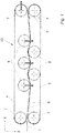
- Figure 1 shows an impregnation system or an impregnation module 13 (s. Figure 3 ), which has two tape loops 4, 5 assigned to one another.
- the first 4 and the second belt loop 5 are formed by respective endless belts which have deflection rollers 7 in their deflection regions and additionally have several further rollers 8 arranged between the respective deflection rollers 7.
- the deflection rollers over which the respective endless belts are guided, span a belt loop area 9 between the upper side and the lower side.
- the first belt loop 4 shown above has three further rollers 8 arranged between the two deflection rollers 7 and forms a surface 6, which is the same as in FIG Figure 1 is assigned second tape loop 5 shown below. That is, the lower side of the tape loop 4 and the upper side of the tape loop 5 are inclined towards each other.
- the textile fabric 1 is passed between the inclined surfaces 6 and subjected to a corresponding pressure, which is intended to ensure that the textile fabric, which consists of a pure textile fabric 3 and a matrix 2 in the form of a film or a fleece, for example.
- the deflecting rollers 7 are adjustable in the x direction, which is indicated by the horizontal thick arrow on the upper right deflecting roller 7. As a result, the tension of the endless belt within the first belt loop 4 can be changed.
- three further rollers 8 are arranged, which are spaced apart from one another which is large enough that the rollers 8 in the belt loop 4 in the belt loop area 9 of further rollers 8 which are arranged in the second belt loop 5 with a immerse yourself in a certain depth.
- the further rollers 8 of the second belt loop 5 can move into the belt loop region (not shown) of the first belt loop 4 immerse, also between the spaced apart additional rollers 8 in the second belt loop 5.
- the wrap angle that the textile fabric in the area of the mutually facing surfaces 6 when conveying over the respective further roller 8 experiences varies.
- the wrap angle guarantees an essentially uniform application of pressure to the textile fabric 1 together with the matrix 2, so that an essentially constant pressure can be exerted on the matrix 2 over a surface area, which thereby penetrates evenly into the actual textile fabric 3 and there a correspondingly causes even distribution.
- the further rollers 8 are offset in the y direction, this causes a shortening of the length of the belt loop, which is compensated for by a corresponding setting or adjustment of the deflecting rollers 7 in the x direction.
- FIG. 2 is shown how the textile fabric consisting of a material layer A, the matrix, and the material layer B, the textile layer, is applied to the further roller 8 through the wrap angle, whereby a compressive force F D is exerted on the textile fabric 1 in the area of the wrap angle is exercised.
- a corresponding belt tension is generated, which in FIG Figure 2 is represented by the tensile force Fz in the direction of the textile fabric 1.
- the corresponding application of pressure when passing through the impregnation module is transferred to the layered material system, namely the textile fabric 1, which means that the flowable material layer of the matrix 2 impregnates the porous material layer of the textile layer 3 due to the pressure acting in the direction of the thickness.
- the pressure builds up along the textile fabric 1 in the conveying direction. This enables the air to escape from the porous layer against the conveying direction.
- the impregnation module shown in principle has the advantage that, via the adjustable wrap angle, the pressure force exerted and thus the respective length of a respective further roller 8 on the textile fabric 1 to penetrate the Matrix 2 in the porous textile material layer 3, ie the textile sheet 1, can be adjusted.
- the deflecting rollers 7 and expediently also the further rollers 8 can be varied in the y-direction within the respective belt loop 4, 5.
- the deflecting rollers 7 can be adjusted at least in the x direction in order to compensate for a shortening of the length by adjusting the further rollers 8 in the y direction for the respective belt loop 4, 5.
- the deflection rollers 7 are arranged one below the other, with such an arrangement there is no need for adjustment in the y-direction, since the pressure introduced linearly into the textile fabric is to be avoided.
- the first tape loop 4 and the second tape loop 5 can have a different length.
- the deflection rollers 7 of one belt loop 4 or 5 can dip into the belt loop region 9 of the other belt loop 4 or 5.
- the deflecting rollers 7 can thus, as it were, take over the function of the further rollers 8 arranged within a respective belt loop.
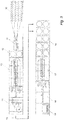
- FIG 3 shows how an impregnation system is classified as an impregnation module 13 in a complete system in the sense of a two-stage processing technology for the production of impregnated unidirectional single-layer tapes and multi-layer composite semi-finished products with a multi-axial reinforcement alignment.
- the basic structure of such an overall system has a creel 10 from which a corresponding number of threads are drawn off, which are combined in a unit downstream of creel 10, a spreading module 11, so that the widest possible spreading is achieved to achieve the lowest possible basis weight becomes.
- the spreading module 11 is followed by a processing unit 12, which has wound the matrix 2, preferably as a film or fleece, so that a flat structure 1 is created by unwinding the matrix 2, which has an actual textile layer 3 and a matrix layer 2, which when passing through the Plant are combined in such a way that the matrix 2 penetrates the porous textile layer 3.
- the system can be adjusted in such a way that the matrix material penetrates completely into the porous textile layer.
- the matrix 2 penetrates into the textile fabric from both sides of the textile layer 3. It is also possible for the matrix 2 to completely penetrate the textile layer.
- the processing unit 12 for the matrix 2 is followed by the impregnation system 13, ie the impregnation module, which is also referred to as the consolidation module.
- the basic structure of this impregnation module is that which is related to Figures 1 and 2 has already been described.
- winding is carried out in the downstream turret winder 14 with simultaneous turning of the impregnated textile fabric.
- the textile fabric 1 after its impregnation an impregnated UD tape 15, which is unwound in a tape unwinding unit 16 and fed to a laminating module 17.
- a lamination module is always used when additional layers are to be laminated onto the impregnated textile fabric, which is done with composite components which are to achieve a given property.
- a transverse cutting module 18 connected downstream of the laminating module 17, the impregnated and laminated textile fabric is cut into lengths which are placed on a pallet in the sense of a palletizing 19.
- the semi-finished products produced in this way can be brought into appropriate shapes for further use due to the use of thermoplastics for the matrix material by heating, which takes place at the place of use without a matrix 2 then having to be added under difficult operating conditions.
Landscapes
- Engineering & Computer Science (AREA)
- Textile Engineering (AREA)
- Chemical & Material Sciences (AREA)
- Mechanical Engineering (AREA)
- Chemical Kinetics & Catalysis (AREA)
- Composite Materials (AREA)
- Life Sciences & Earth Sciences (AREA)
- Proteomics, Peptides & Aminoacids (AREA)
- Dispersion Chemistry (AREA)
- Fluid Mechanics (AREA)
- Physics & Mathematics (AREA)
- Reinforced Plastic Materials (AREA)
- Treatment Of Fiber Materials (AREA)
Priority Applications (3)
| Application Number | Priority Date | Filing Date | Title |
|---|---|---|---|
| EP19161304.1A EP3705251B1 (fr) | 2019-03-07 | 2019-03-07 | Installation d'imprégnation et procédé d'imprégnation d'une structure plane textile pour composants composites |
| US16/807,925 US11453976B2 (en) | 2019-03-07 | 2020-03-03 | Impregnation system and method for impregnating a textile fabric for composite components |
| CN202010149323.2A CN111663265B (zh) | 2019-03-07 | 2020-03-04 | 用以对用于复合构件的纺织面料加以浸渍的浸渍设备和方法 |
Applications Claiming Priority (1)
| Application Number | Priority Date | Filing Date | Title |
|---|---|---|---|
| EP19161304.1A EP3705251B1 (fr) | 2019-03-07 | 2019-03-07 | Installation d'imprégnation et procédé d'imprégnation d'une structure plane textile pour composants composites |
Publications (2)
| Publication Number | Publication Date |
|---|---|
| EP3705251A1 true EP3705251A1 (fr) | 2020-09-09 |
| EP3705251B1 EP3705251B1 (fr) | 2023-05-03 |
Family
ID=65724267
Family Applications (1)
| Application Number | Title | Priority Date | Filing Date |
|---|---|---|---|
| EP19161304.1A Active EP3705251B1 (fr) | 2019-03-07 | 2019-03-07 | Installation d'imprégnation et procédé d'imprégnation d'une structure plane textile pour composants composites |
Country Status (3)
| Country | Link |
|---|---|
| US (1) | US11453976B2 (fr) |
| EP (1) | EP3705251B1 (fr) |
| CN (1) | CN111663265B (fr) |
Families Citing this family (1)
| Publication number | Priority date | Publication date | Assignee | Title |
|---|---|---|---|---|
| CN117229563B (zh) * | 2023-09-26 | 2024-08-30 | 东莞市越辉新材料科技有限公司 | 一种硅橡胶海绵材料生产工艺及设备 |
Citations (6)
| Publication number | Priority date | Publication date | Assignee | Title |
|---|---|---|---|---|
| DE2856506A1 (de) * | 1978-05-18 | 1979-11-29 | Owens Corning Fiberglass Corp | Verfahren und vorrichtung zur herstellung einer verstaerkten formmasse in bahnform |
| EP0013548A1 (fr) | 1979-01-04 | 1980-07-23 | VOEST-ALPINE Aktiengesellschaft | Dispositif pour la déshydratation de matières contenant de l'eau |
| JPH05228933A (ja) * | 1992-02-24 | 1993-09-07 | Yokohama Rubber Co Ltd:The | 液体含浸装置 |
| DE60003766T2 (de) | 1999-10-20 | 2004-06-03 | Saint-Gobain Vetrotex France S.A. | Verfahren und Vorrichtung zur Herstellung eines Verbundbandes geformt aus Verstärkungsfasern und thermoplastischem Material |
| DE102009046670A1 (de) * | 2009-11-12 | 2011-05-19 | Dieffenbacher Gmbh + Co. Kg | Anlage zur Herstellung von faserverstärkten Formteilen und Verfahren zum Betreiben einer Anlage zur Herstellung von faserverstärkten Formteilen |
| US20160271860A1 (en) | 2014-07-01 | 2016-09-22 | Teijin Limited | Production Method of Fiber-Reinforced Plastic |
Family Cites Families (4)
| Publication number | Priority date | Publication date | Assignee | Title |
|---|---|---|---|---|
| US4219524A (en) * | 1979-01-10 | 1980-08-26 | Owens-Corning Fiberglas Corporation | Method and apparatus for producing sheet molding compound |
| US5201979A (en) * | 1987-05-08 | 1993-04-13 | Research Association For New Technology Development Of High Performance Polymer | Method of manufacturing a sheet-prepreg reinforced with fibers |
| FR2894993A1 (fr) * | 2005-12-19 | 2007-06-22 | Rhodia Recherches & Tech | Nouveau procede d'impregnation d'une surface textile |
| CN109267269B (zh) * | 2018-12-03 | 2021-05-04 | 嵊州市诚宇工程建设有限公司 | 一种用于纺织面料浸轧的装置 |
-
2019
- 2019-03-07 EP EP19161304.1A patent/EP3705251B1/fr active Active
-
2020
- 2020-03-03 US US16/807,925 patent/US11453976B2/en active Active
- 2020-03-04 CN CN202010149323.2A patent/CN111663265B/zh active Active
Patent Citations (6)
| Publication number | Priority date | Publication date | Assignee | Title |
|---|---|---|---|---|
| DE2856506A1 (de) * | 1978-05-18 | 1979-11-29 | Owens Corning Fiberglass Corp | Verfahren und vorrichtung zur herstellung einer verstaerkten formmasse in bahnform |
| EP0013548A1 (fr) | 1979-01-04 | 1980-07-23 | VOEST-ALPINE Aktiengesellschaft | Dispositif pour la déshydratation de matières contenant de l'eau |
| JPH05228933A (ja) * | 1992-02-24 | 1993-09-07 | Yokohama Rubber Co Ltd:The | 液体含浸装置 |
| DE60003766T2 (de) | 1999-10-20 | 2004-06-03 | Saint-Gobain Vetrotex France S.A. | Verfahren und Vorrichtung zur Herstellung eines Verbundbandes geformt aus Verstärkungsfasern und thermoplastischem Material |
| DE102009046670A1 (de) * | 2009-11-12 | 2011-05-19 | Dieffenbacher Gmbh + Co. Kg | Anlage zur Herstellung von faserverstärkten Formteilen und Verfahren zum Betreiben einer Anlage zur Herstellung von faserverstärkten Formteilen |
| US20160271860A1 (en) | 2014-07-01 | 2016-09-22 | Teijin Limited | Production Method of Fiber-Reinforced Plastic |
Also Published As
| Publication number | Publication date |
|---|---|
| EP3705251B1 (fr) | 2023-05-03 |
| US20200283951A1 (en) | 2020-09-10 |
| CN111663265B (zh) | 2023-10-27 |
| US11453976B2 (en) | 2022-09-27 |
| CN111663265A (zh) | 2020-09-15 |
Similar Documents
| Publication | Publication Date | Title |
|---|---|---|
| DE69212489T2 (de) | Verfahren und Gegenstand zur Herstellung von Matten | |
| DE60119504T2 (de) | Verfahren und vorrichtung zur herstellung eines verbundprofils aus organischem, thermoplastischem, durch verstärkungsfasern verstärktem kunststoff | |
| EP2181217B1 (fr) | Procédé et dispositif pour la fabrication en continu d'une bande multiaxiale non tissée | |
| DE69429736T2 (de) | Verfahren zum herstellen von langfaserverstärkten harzzusammensetzungen | |
| DE102017220330A1 (de) | Einrichtung und Verfahren zum Herstellen eines Tow-Prepregs | |
| EP3260591B1 (fr) | Système de transport de textiles techniques pendant leur fabrication, installation de fabrication de textiles techniques comprenant un tel système de transport et procédé de fabrication de textiles techniques comprenant un tel dispositif | |
| EP0365826B2 (fr) | Procédé et dispositif pour la production de panneaux à base de fibres minérales | |
| EP0185742B1 (fr) | Procede pour impregner un materiau de support comprimable plan de resine synthetique et installation pour realiser ce procede | |
| EP3705251B1 (fr) | Installation d'imprégnation et procédé d'imprégnation d'une structure plane textile pour composants composites | |
| DE2105955A1 (de) | Verfahren und Vorrichtung zum Herstellen von Hohlkörpern aus Reak tionsharzen, die mit Fasern verstärkt sind | |
| EP3280664A1 (fr) | Dispositif servant à réduire le nombre de filaments d'un renforcement à base de fibres | |
| DE102008057463A1 (de) | Feder aus einem Faserverbundwerkstoff sowie Verfahren und Vorrichtung zur Herstellung derselben | |
| DE2146309B2 (fr) | ||
| DE102016120197B4 (de) | Anlage und Verfahren zur Herstellung einer Faserpreform | |
| DE102014106460A1 (de) | Textilmaschine | |
| DE102006052136B4 (de) | Verfahren und Vorrichtung zur kontinuierlichen Herstellung von Prepregs | |
| EP3310544A1 (fr) | Dispositif et procédé de fabrication d'une préforme multicouche courbée à partir de fibres d'un matériau composite renforcé par fibres | |
| DE3324302C2 (de) | Vorrichtung zum Herstellen von mehrlagigen Schichtstoffplatten | |
| DE102008057462B4 (de) | Feder aus einem Faserverbundwerkstoff sowie Verfahren und Vorrichtung zur Herstellung derselben | |
| DE102016111080B4 (de) | Verfahren zum Herstellen von Halbzeugen für Faser-Kunststoff-Verbundbauteile | |
| DE102018203360B4 (de) | Temperiervorrichtung für und eine Organobandmaterialanlage zur Herstellung von flächigen Faserverbundhalbzeugen, sowie ein entsprechendes Herstellungsverfahren | |
| DE3042539C2 (de) | Verfahren zum Herstellen von langgestreckten Bauteilen aus faserverstärkten Werkstoffen | |
| DE102018105531A1 (de) | Verfahren zum Bearbeiten von Schaumstoffen mittels Förderbändern | |
| DE2124139B2 (de) | Verfahren zur Herstellung von Schichtstoffen und Vorrichtung zur Durchführung des Verfahrens | |
| EP3755833B1 (fr) | Structure de fil |
Legal Events
| Date | Code | Title | Description |
|---|---|---|---|
| PUAI | Public reference made under article 153(3) epc to a published international application that has entered the european phase |
Free format text: ORIGINAL CODE: 0009012 |
|
| STAA | Information on the status of an ep patent application or granted ep patent |
Free format text: STATUS: THE APPLICATION HAS BEEN PUBLISHED |
|
| AK | Designated contracting states |
Kind code of ref document: A1 Designated state(s): AL AT BE BG CH CY CZ DE DK EE ES FI FR GB GR HR HU IE IS IT LI LT LU LV MC MK MT NL NO PL PT RO RS SE SI SK SM TR |
|
| AX | Request for extension of the european patent |
Extension state: BA ME |
|
| STAA | Information on the status of an ep patent application or granted ep patent |
Free format text: STATUS: REQUEST FOR EXAMINATION WAS MADE |
|
| 17P | Request for examination filed |
Effective date: 20201103 |
|
| RBV | Designated contracting states (corrected) |
Designated state(s): AL AT BE BG CH CY CZ DE DK EE ES FI FR GB GR HR HU IE IS IT LI LT LU LV MC MK MT NL NO PL PT RO RS SE SI SK SM TR |
|
| STAA | Information on the status of an ep patent application or granted ep patent |
Free format text: STATUS: EXAMINATION IS IN PROGRESS |
|
| 17Q | First examination report despatched |
Effective date: 20210222 |
|
| GRAP | Despatch of communication of intention to grant a patent |
Free format text: ORIGINAL CODE: EPIDOSNIGR1 |
|
| STAA | Information on the status of an ep patent application or granted ep patent |
Free format text: STATUS: GRANT OF PATENT IS INTENDED |
|
| INTG | Intention to grant announced |
Effective date: 20221024 |
|
| GRAS | Grant fee paid |
Free format text: ORIGINAL CODE: EPIDOSNIGR3 |
|
| GRAA | (expected) grant |
Free format text: ORIGINAL CODE: 0009210 |
|
| STAA | Information on the status of an ep patent application or granted ep patent |
Free format text: STATUS: THE PATENT HAS BEEN GRANTED |
|
| AK | Designated contracting states |
Kind code of ref document: B1 Designated state(s): AL AT BE BG CH CY CZ DE DK EE ES FI FR GB GR HR HU IE IS IT LI LT LU LV MC MK MT NL NO PL PT RO RS SE SI SK SM TR |
|
| REG | Reference to a national code |
Ref country code: GB Ref legal event code: FG4D Free format text: NOT ENGLISH |
|
| REG | Reference to a national code |
Ref country code: DE Ref legal event code: R096 Ref document number: 502019007595 Country of ref document: DE |
|
| REG | Reference to a national code |
Ref country code: AT Ref legal event code: REF Ref document number: 1564209 Country of ref document: AT Kind code of ref document: T Effective date: 20230515 Ref country code: CH Ref legal event code: EP |
|
| REG | Reference to a national code |
Ref country code: IE Ref legal event code: FG4D Free format text: LANGUAGE OF EP DOCUMENT: GERMAN |
|
| P01 | Opt-out of the competence of the unified patent court (upc) registered |
Effective date: 20230528 |
|
| REG | Reference to a national code |
Ref country code: NL Ref legal event code: FP |
|
| REG | Reference to a national code |
Ref country code: LT Ref legal event code: MG9D |
|
| PG25 | Lapsed in a contracting state [announced via postgrant information from national office to epo] |
Ref country code: SE Free format text: LAPSE BECAUSE OF FAILURE TO SUBMIT A TRANSLATION OF THE DESCRIPTION OR TO PAY THE FEE WITHIN THE PRESCRIBED TIME-LIMIT Effective date: 20230503 Ref country code: PT Free format text: LAPSE BECAUSE OF FAILURE TO SUBMIT A TRANSLATION OF THE DESCRIPTION OR TO PAY THE FEE WITHIN THE PRESCRIBED TIME-LIMIT Effective date: 20230904 Ref country code: NO Free format text: LAPSE BECAUSE OF FAILURE TO SUBMIT A TRANSLATION OF THE DESCRIPTION OR TO PAY THE FEE WITHIN THE PRESCRIBED TIME-LIMIT Effective date: 20230803 Ref country code: ES Free format text: LAPSE BECAUSE OF FAILURE TO SUBMIT A TRANSLATION OF THE DESCRIPTION OR TO PAY THE FEE WITHIN THE PRESCRIBED TIME-LIMIT Effective date: 20230503 |
|
| PG25 | Lapsed in a contracting state [announced via postgrant information from national office to epo] |
Ref country code: RS Free format text: LAPSE BECAUSE OF FAILURE TO SUBMIT A TRANSLATION OF THE DESCRIPTION OR TO PAY THE FEE WITHIN THE PRESCRIBED TIME-LIMIT Effective date: 20230503 Ref country code: PL Free format text: LAPSE BECAUSE OF FAILURE TO SUBMIT A TRANSLATION OF THE DESCRIPTION OR TO PAY THE FEE WITHIN THE PRESCRIBED TIME-LIMIT Effective date: 20230503 Ref country code: LV Free format text: LAPSE BECAUSE OF FAILURE TO SUBMIT A TRANSLATION OF THE DESCRIPTION OR TO PAY THE FEE WITHIN THE PRESCRIBED TIME-LIMIT Effective date: 20230503 Ref country code: LT Free format text: LAPSE BECAUSE OF FAILURE TO SUBMIT A TRANSLATION OF THE DESCRIPTION OR TO PAY THE FEE WITHIN THE PRESCRIBED TIME-LIMIT Effective date: 20230503 Ref country code: IS Free format text: LAPSE BECAUSE OF FAILURE TO SUBMIT A TRANSLATION OF THE DESCRIPTION OR TO PAY THE FEE WITHIN THE PRESCRIBED TIME-LIMIT Effective date: 20230903 Ref country code: HR Free format text: LAPSE BECAUSE OF FAILURE TO SUBMIT A TRANSLATION OF THE DESCRIPTION OR TO PAY THE FEE WITHIN THE PRESCRIBED TIME-LIMIT Effective date: 20230503 Ref country code: GR Free format text: LAPSE BECAUSE OF FAILURE TO SUBMIT A TRANSLATION OF THE DESCRIPTION OR TO PAY THE FEE WITHIN THE PRESCRIBED TIME-LIMIT Effective date: 20230804 |
|
| PG25 | Lapsed in a contracting state [announced via postgrant information from national office to epo] |
Ref country code: FI Free format text: LAPSE BECAUSE OF FAILURE TO SUBMIT A TRANSLATION OF THE DESCRIPTION OR TO PAY THE FEE WITHIN THE PRESCRIBED TIME-LIMIT Effective date: 20230503 |
|
| PG25 | Lapsed in a contracting state [announced via postgrant information from national office to epo] |
Ref country code: SK Free format text: LAPSE BECAUSE OF FAILURE TO SUBMIT A TRANSLATION OF THE DESCRIPTION OR TO PAY THE FEE WITHIN THE PRESCRIBED TIME-LIMIT Effective date: 20230503 |
|
| PG25 | Lapsed in a contracting state [announced via postgrant information from national office to epo] |
Ref country code: SM Free format text: LAPSE BECAUSE OF FAILURE TO SUBMIT A TRANSLATION OF THE DESCRIPTION OR TO PAY THE FEE WITHIN THE PRESCRIBED TIME-LIMIT Effective date: 20230503 Ref country code: SK Free format text: LAPSE BECAUSE OF FAILURE TO SUBMIT A TRANSLATION OF THE DESCRIPTION OR TO PAY THE FEE WITHIN THE PRESCRIBED TIME-LIMIT Effective date: 20230503 Ref country code: RO Free format text: LAPSE BECAUSE OF FAILURE TO SUBMIT A TRANSLATION OF THE DESCRIPTION OR TO PAY THE FEE WITHIN THE PRESCRIBED TIME-LIMIT Effective date: 20230503 Ref country code: EE Free format text: LAPSE BECAUSE OF FAILURE TO SUBMIT A TRANSLATION OF THE DESCRIPTION OR TO PAY THE FEE WITHIN THE PRESCRIBED TIME-LIMIT Effective date: 20230503 Ref country code: DK Free format text: LAPSE BECAUSE OF FAILURE TO SUBMIT A TRANSLATION OF THE DESCRIPTION OR TO PAY THE FEE WITHIN THE PRESCRIBED TIME-LIMIT Effective date: 20230503 Ref country code: CZ Free format text: LAPSE BECAUSE OF FAILURE TO SUBMIT A TRANSLATION OF THE DESCRIPTION OR TO PAY THE FEE WITHIN THE PRESCRIBED TIME-LIMIT Effective date: 20230503 |
|
| REG | Reference to a national code |
Ref country code: DE Ref legal event code: R097 Ref document number: 502019007595 Country of ref document: DE |
|
| PLBE | No opposition filed within time limit |
Free format text: ORIGINAL CODE: 0009261 |
|
| STAA | Information on the status of an ep patent application or granted ep patent |
Free format text: STATUS: NO OPPOSITION FILED WITHIN TIME LIMIT |
|
| 26N | No opposition filed |
Effective date: 20240206 |
|
| PGFP | Annual fee paid to national office [announced via postgrant information from national office to epo] |
Ref country code: NL Payment date: 20240326 Year of fee payment: 6 |
|
| PGFP | Annual fee paid to national office [announced via postgrant information from national office to epo] |
Ref country code: DE Payment date: 20240328 Year of fee payment: 6 |
|
| PG25 | Lapsed in a contracting state [announced via postgrant information from national office to epo] |
Ref country code: SI Free format text: LAPSE BECAUSE OF FAILURE TO SUBMIT A TRANSLATION OF THE DESCRIPTION OR TO PAY THE FEE WITHIN THE PRESCRIBED TIME-LIMIT Effective date: 20230503 |
|
| PG25 | Lapsed in a contracting state [announced via postgrant information from national office to epo] |
Ref country code: SI Free format text: LAPSE BECAUSE OF FAILURE TO SUBMIT A TRANSLATION OF THE DESCRIPTION OR TO PAY THE FEE WITHIN THE PRESCRIBED TIME-LIMIT Effective date: 20230503 Ref country code: IT Free format text: LAPSE BECAUSE OF FAILURE TO SUBMIT A TRANSLATION OF THE DESCRIPTION OR TO PAY THE FEE WITHIN THE PRESCRIBED TIME-LIMIT Effective date: 20230503 |