EP3705158A1 - Gehäuse für ein implantierbares medizinisches gerät - Google Patents
Gehäuse für ein implantierbares medizinisches gerät Download PDFInfo
- Publication number
- EP3705158A1 EP3705158A1 EP19168592.4A EP19168592A EP3705158A1 EP 3705158 A1 EP3705158 A1 EP 3705158A1 EP 19168592 A EP19168592 A EP 19168592A EP 3705158 A1 EP3705158 A1 EP 3705158A1
- Authority
- EP
- European Patent Office
- Prior art keywords
- device housing
- housing
- front side
- hmax
- bmax
- Prior art date
- Legal status (The legal status is an assumption and is not a legal conclusion. Google has not performed a legal analysis and makes no representation as to the accuracy of the status listed.)
- Granted
Links
Images


Classifications
-
- A—HUMAN NECESSITIES
- A61—MEDICAL OR VETERINARY SCIENCE; HYGIENE
- A61N—ELECTROTHERAPY; MAGNETOTHERAPY; RADIATION THERAPY; ULTRASOUND THERAPY
- A61N1/00—Electrotherapy; Circuits therefor
- A61N1/18—Applying electric currents by contact electrodes
- A61N1/32—Applying electric currents by contact electrodes alternating or intermittent currents
- A61N1/36—Applying electric currents by contact electrodes alternating or intermittent currents for stimulation
- A61N1/372—Arrangements in connection with the implantation of stimulators
- A61N1/375—Constructional arrangements, e.g. casings
- A61N1/37512—Pacemakers
-
- A—HUMAN NECESSITIES
- A61—MEDICAL OR VETERINARY SCIENCE; HYGIENE
- A61N—ELECTROTHERAPY; MAGNETOTHERAPY; RADIATION THERAPY; ULTRASOUND THERAPY
- A61N1/00—Electrotherapy; Circuits therefor
- A61N1/18—Applying electric currents by contact electrodes
- A61N1/32—Applying electric currents by contact electrodes alternating or intermittent currents
- A61N1/36—Applying electric currents by contact electrodes alternating or intermittent currents for stimulation
- A61N1/372—Arrangements in connection with the implantation of stimulators
- A61N1/375—Constructional arrangements, e.g. casings
-
- A—HUMAN NECESSITIES
- A61—MEDICAL OR VETERINARY SCIENCE; HYGIENE
- A61N—ELECTROTHERAPY; MAGNETOTHERAPY; RADIATION THERAPY; ULTRASOUND THERAPY
- A61N1/00—Electrotherapy; Circuits therefor
- A61N1/18—Applying electric currents by contact electrodes
- A61N1/32—Applying electric currents by contact electrodes alternating or intermittent currents
- A61N1/38—Applying electric currents by contact electrodes alternating or intermittent currents for producing shock effects
- A61N1/39—Heart defibrillators
- A61N1/3956—Implantable devices for applying electric shocks to the heart, e.g. for cardioversion
-
- A—HUMAN NECESSITIES
- A61—MEDICAL OR VETERINARY SCIENCE; HYGIENE
- A61N—ELECTROTHERAPY; MAGNETOTHERAPY; RADIATION THERAPY; ULTRASOUND THERAPY
- A61N1/00—Electrotherapy; Circuits therefor
- A61N1/18—Applying electric currents by contact electrodes
- A61N1/32—Applying electric currents by contact electrodes alternating or intermittent currents
- A61N1/38—Applying electric currents by contact electrodes alternating or intermittent currents for producing shock effects
- A61N1/39—Heart defibrillators
- A61N1/3968—Constructional arrangements, e.g. casings
-
- A—HUMAN NECESSITIES
- A61—MEDICAL OR VETERINARY SCIENCE; HYGIENE
- A61B—DIAGNOSIS; SURGERY; IDENTIFICATION
- A61B17/00—Surgical instruments, devices or methods
- A61B17/34—Trocars; Puncturing needles
- A61B17/3468—Trocars; Puncturing needles for implanting or removing devices, e.g. prostheses, implants, seeds, wires
Definitions
- the present invention relates to housings for implantable medical devices (IMD).
- IMD implantable medical devices
- Housings for IMDs accommodate the most important device components and protect them from the environment surrounding the implantation site.
- the device housings can have interfaces to the outside, e.g. for the electrical and mechanical coupling of device components (for example for stimulation electrodes for pacemaker implants) or sensor interfaces for measuring body parameters.
- IMDs whose device housings are implanted in a patient's skin or tissue pocket (for example, in the case of pacemaker implants or spinal cord stimulators).
- the device housings should be as small as possible and shaped so that they are not perceived as annoying by the patient.
- flat, rounded housing shapes are known that cause a small bulge in the skin that protrudes as little as possible.
- Pacemakers, implantable cardioverter defibrillators (ICD) or CRT (Cardiac Resynchronization Therapy) devices usually have a flat, rounded housing made of metal.
- the housing is mechanically connected at the end to a header component (header in the following), which typically consists of cast epoxy resin and provides the connections for the electrode lines.
- Electrical lines lead from the device housing into the header to the connections for the electrode lines and thus ensure the electrical connection between the electrodes and the components arranged inside the housing such as the device processor, the battery or, in the case of ICDs, the Shock capacitor.
- the device housing with header is implanted in the upper chest area, above the ribs, below the collarbone in a skin or tissue pocket.
- the device housing in combination with the header is referred to below as the housing arrangement.
- cardiac pacemakers, ICDs and CRT devices are known in which the housing arrangement comprising the device housing and header is flat and has a circular outer contour.
- a problem with such housing assemblies is that they can rotate easily in the skin or tissue pocket.
- the electrode lines connected to the header are rotated at the same time, which can lead to an electrode break.
- Housing arrangements are also known in which the device housing is wider than it is high, or higher than it is wide.
- a disadvantage of such housing arrangements is that the device housing has a tendency to "rock" on the patient's ribs. The tilting is caused by the space existing between the patient's ribs and the device housing, which is relatively large for such housing arrangements, since the device housing has a relatively elongated flat side which does not follow the contour of the ribs. The 'tilting' is pronounced and uncomfortable, especially in patients with a small chest, whose rib contour has a smaller circular radius.
- the invention is based on the object of providing a device housing for an IMD that is comfortable for the patient to wear under the skin, ie painless and essentially without noticeable tension and tensile forces. It is also an object of the invention to provide a device housing for an IMD which "tilts" as little as possible when it is implanted over the patient's ribs.
- Another object of the invention is to provide a device housing for an IMD that does not simply twist when implanted.
- a device housing according to the invention according to claim 1 as well as a housing arrangement comprising the device housing according to claim 12, and a method for implanting the housing arrangement according to claim 14.
- the proposed device housing has an optimal geometry to enable the patient to wear it comfortably, ie the 'tilting' on the ribs is avoided or greatly reduced because the device housing does not have an elongated surface. At the same time, turning in the skin or tissue pocket is prevented because the housing is not circular.
- the ratio R i. Bmax / Hmax a value between 1.1 and 1.30; or between 1.15 and 1.275, or between 1.2 and 1.275; or from 1.25.
- the front side has a maximum width (Bmax) of 40 mm to 70 mm; or from 50 mm to 65 mm; or from 55 mm to 65 mm; or from 60 mm.
- the front side has a maximum height (Hmax) a value of 40 mm to 70 mm; or from 40 mm to 60 mm; or from 45 mm to 55 mm; or from 45 mm to 52 mm; or from 48 mm.
- Hmax maximum height
- the device case has a maximum thickness Dmax, the thickness being measured perpendicular to the plane of the front side, and the maximum thickness being 9 mm to 15 mm; or 9 mm to 12 mm, or 10 mm to 11 mm; or of 10 mm.
- the thicknesses mentioned allow an ergonomic, thin device housing, with sufficient internal volume to accommodate the device components, if other proposed geometries are selected for the device housing in combination.
- the device housing has a rear side which is arranged congruently and opposite to the front side, and the flat front side adjoining a straight upper edge of the rear side.
- the device housing can also comprise two housing shells, the first housing shell having the front side and the second housing shell having the rear side, the first and second housing shells being symmetrical.
- the IMD with the device housing according to the invention is simply turned over and can be implanted on the mirror side, while it has the same comfort properties for the patient as for a regular patient with an IMD implanted on the left side.
- the outer contour of the front of the device housing has curves with at least two different curve radii.
- a maximum curve radius of 12 cm, or 11 cm, or 10 cm, or 9.5 cm is not exceeded.
- the ratio of the area of the front side to the area of an ellipse that is spanned by the maximum width (Bmax) and maximum height (Hmax) of the front side ie Fl a ⁇ che front Fl a ⁇ che ellipse , at most 1.5; or at most 1.4; or at most 1.3; or at most 1.2; or at most 1.15; or at most 1.1.
- the choice of the proposed 'fill factors' ensures that, on the one hand, the shape of the device housing remains 'circular' or at least 'elliptical', so that sharp corners of the contour and elongated surfaces are avoided in order to increase wearing comfort and avoid 'tipping' .
- the device housing has rounded edges. These increase the comfort for the patient.
- a housing arrangement for an IMD which comprises a device housing according to the invention and a header (3).
- the header is connected to the device housing on the flat face of the device housing.
- the IMD is a cardiac pacemaker, an implantable cardioverter defibrillator or a CRT device.
- the cut has a length less than or equal to the maximum width (Bmax) of the front of the device housing.
- the cut can have a length that is less than or equal to the maximum height (Hmax) of the front side plus a height of the header. In this way, an incision of the optimal length is applied for the preparation of a skin or tissue pocket.
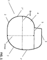
- Figure 1 shows the contours of a housing arrangement 1 according to the invention, comprising device housing 2 and header 3.
- Device housing 2 has a front side 4 and a flat front side 6, which is arranged perpendicular to front side 4 and adjoins a straight upper edge 5 of the front side.
- the front side 4 has a maximum width Bmax, which is measured parallel to the straight upper edge 5.
- Front side 4 also has a maximum height Hmax, which is measured perpendicular to the straight upper edge 5.
- the outer contour of the front side 4 comprises curves with at least two different curve radii 7, 7 ', 7 ".
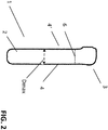
- Figure 2 shows a schematic side view of the housing arrangement according to the invention. You can see the maximum thickness of the device housing Dmax, which is perpendicular to the front 4 is measured.
- the device housing 2 also has a rear side 4 ′, which can be designed to be congruent with the front side 4.
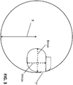
- Figure 3 shows schematically a measurement of the curve radius 7 '.
- the corresponding segment of the circle is shown in dashed lines.
- a circle with a corresponding circle segment is superimposed and the circle radius 81 corresponds to the curve radius 7 '.
- Figure 4 shows schematically the determination of the filling factor, which is formed by the ratio of the area of the front side 4 to a rectangle 9, which is spanned by Bmax and Hmax.
- the hatched area corresponds to the part of the rectangular area that is not filled by the area of the front 4.
- Figure 5 shows schematically the determination of the filling factor, which is formed by the ratio of the area of the front side 4 to an ellipse 10, which has Bmax and Hmax as the major and minor axes.
- the area of the front side 4 not covered by the hatched area corresponds to the part of the area which projects beyond that of the ellipse.
Landscapes
- Health & Medical Sciences (AREA)
- Life Sciences & Earth Sciences (AREA)
- Radiology & Medical Imaging (AREA)
- Engineering & Computer Science (AREA)
- Biomedical Technology (AREA)
- Nuclear Medicine, Radiotherapy & Molecular Imaging (AREA)
- Animal Behavior & Ethology (AREA)
- General Health & Medical Sciences (AREA)
- Public Health (AREA)
- Veterinary Medicine (AREA)
- Heart & Thoracic Surgery (AREA)
- Cardiology (AREA)
- Biophysics (AREA)
- Electrotherapy Devices (AREA)
- Prostheses (AREA)
Abstract
Description
- Die vorliegende Erfindung betrifft Gehäuse für implantierbare medizinische Geräte (Implantable Medical Device, IMD).
- Gehäuse für IMDs beherbergen die wichtigsten Gerätekomponenten und schützen diese vor dem Umgebungsmilieu des Implantationsortes. Die Gerätegehäuse können Schnittstellen nach außen aufweisen, z.B. zur elektrischen und mechanischen Ankopplung von Gerätekomponenten (beispielsweise für Stimulationselektroden für Schrittmacherimplantate) oder Sensorschnittstellen zur Messung von Körperparametern.
- Es gibt IMDs, deren Gerätegehäuse in einer Haut- oder Gewebetasche des Patienten implantiert werden (Zum Beispiel bei Herzschrittmacherimplantaten oder Rückenmarksstimulatoren). Die Gerätegehäuse sollten so klein wie möglich dimensioniert und so geformt sein, dass sie nicht vom Patienten als störend empfunden werden. Im Stand der Technik sind flache, abgerundete Gehäuseformen bekannt, die eine kleine Wölbung in der Haut verursachen, die möglichst wenig heraussteht.
- Herzschrittmacher, implantierbare Kardioverter-Defibrillatoren (Implantable Cardioverter-Defibrillator, ICD) oder CRT (Cardiac Resynchronization Therapy) Geräte weisen in der Regel ein flaches, abgerundetes Gehäuse aus Metall auf. Das Gehäuse ist an der Stirnseite mit einer Header-Komponente (Header im Folgenden) mechanisch verbunden, die typischerweise aus gegossenem Epoxidharz besteht und die Anschlüsse für die Elektrodenleitungen bereitstellt. Elektrische Leitungen führen aus dem Gerätegehäuse in den Header zu den Anschlüssen für die Elektrodenleitungen und gewährleisten so die elektrische Verbindung zwischen Elektroden und den im Inneren des Gehäuses angeordneten Komponenten wie dem Geräteprozessor, der Batterie oder bei ICDs dem Schock-Kondensator. Das Gerätegehäuse mit Header wird im oberen Brustbereich, über den Rippen, unterhalb des Schlüsselbeins in einer Haut- oder Gewebetasche implantiert. Das Gerätegehäuse im Verbund mit dem Header wird im Folgenden als Gehäuseanordnung bezeichnet.
- Im Stand der Technik sind Herzschrittmacher, ICDs und CRT-Geräte bekannt, bei denen die Gehäuseanordnung aus Gerätegehäuse und Header flach ausgebildet ist und eine kreisrunde Außenkontur aufweist. Ein Problem solcher Gehäuseanordnungen besteht darin, dass sie sich in der Haut- bzw. Gewebetasche leicht drehen kann. Die an den Header angeschlossenen Elektrodenleitungen werden dabei mitgedreht, wodurch ein Elektrodenbruch entstehen kann.
- Auch bekannt sind Gehäuseanordnungen, bei denen das Gerätegehäuse breiter ist als hoch, oder höher ist als breit. Ein Nachteil solcher Gehäuseanordnungen besteht darin, dass das Gerätegehäuse dazu neigt, auf den Rippen des Patienten zu 'kippeln'. Das Kippeln ist bedingt durch den zwischen den Rippen des Patienten und dem Gerätegehäuse existierenden Raum, der verhältnismäßig groß ist für solche Gehäuseanordnungen, da das Gerätegehäuse über eine relativ langgestreckte flache Seite verfügt, die nicht der Rippenkontur folgt. Insbesondere bei Patienten mit kleinem Brustkorb, deren Rippenkontur einen kleineren Kreisradius aufweisen, ist das 'Kippeln' ausgeprägt und unangenehm.
- Bei der Implantation solcher Gehäuseanordnungen wird ein vergleichsmäßig kleiner Schnitt in die Haut des Patienten gemacht, was den Nachteil mit sich bringt, dass der Arzt eingeschränkten Gestaltungsspielraum bei der Formung der Haut- bzw. Gewebetasche zur Verfügung hat.
- Der Erfindung liegt die Aufgabe zugrunde, ein Gerätegehäuse für ein IMD bereitzustellen, das sich für den Patienten angenehm unter der Haut zu tragen ist, d.h. schmerzfrei und im Wesentlichen ohne spürbare Spann- und Zugkräfte. Auch ist eine Aufgabe der Erfindung, ein Gerätegehäuse für ein IMD bereitzustellen, das möglichst wenig ,kippelt', wenn es über den Rippen des Patienten implantiert wird.
- Eine weitere Aufgabe der Erfindung liegt darin, ein Gerätegehäuse für ein IMD bereitzustellen, das sich im implantierten Zustand nicht einfach verdreht.
- Es ist eine weitere Aufgabe der Erfindung, ein Gerätegehäuse für ein IMD bereitzustellen, das sich einfach, schnell und kontrolliert implantieren lässt.
- Die Aufgaben werden durch ein erfindungsgemäßes Gerätegehäuse nach Anspruch 1, sowie eine Gehäuseanordnung umfassend das Gerätegehäuse nach Anspruch 12, und einem Verfahren zur Implantation der Gehäuseanordnung gemäß Anspruch 14 gelöst.
- Vorteilhafte Ausführungsbeispiele der Erfindung finden sich in den abhängigen Ansprüchen.
- Gemäß der erfinderischen Lösung wird ein Gerätegehäuse für ein IMD vorgeschlagen,
- wobei das Gerätegehäuse aufweist:
- eine Vorderseite,
- eine ebene Stirnseite, die senkrecht zu Vorderseite angeordnet ist und an eine gerade Oberkante der Vorderseite anschließt,
- wobei die Vorderseite eine maximale Breite (Bmax) aufweist, die parallel zur geraden Oberkante gemessen wird, und eine maximale Höhe (Hmax) aufweist, die senkrecht zur geraden Oberkante gemessen wird,
- dadurch gekennzeichnet, dass das Verhältnis R von maximaler Breite (Bmax) und maximaler Höhe (Hmax), d.h. Bmax/Hmax, einen Wert zwischen 1,05 und 1,35 aufweist.
- Das vorschlagsgemäße Gerätegehäuse weist auf diese Weise eine optimale Geometrie auf, um dem Patienten ein angenehmes Tragegefühl zu ermöglichen, d.h. das 'Kippeln' auf den Rippen wird vermieden bis stark gemindert, da das Gerätegehäuse über keine langgestreckte Fläche verfügt. Gleichzeitig wird ein Drehen in der Haut- bzw. Gewebetasche verhindert, da das Gehäuse nicht kreisrund ist.
- Gemäß vorteilhafter Ausführungsbeispiele hat das Verhältnis R, d.h. Bmax/Hmax einen Wert zwischen 1,1 und 1,30; oder zwischen 1,15 und 1,275, oder zwischen 1,2 und 1,275; oder von 1,25.
- Des Weiteren, gemäß vorteilhaften Aspekten der Erfindung, hat die Vorderseite eine maximale Breite (Bmax) von 40 mm bis 70 mm; oder von 50 mm bis 65 mm; oder von 55 mm bis 65 mm; oder von 60 mm.
- Gemäß weiteren Ausführungsbeispielen der Erfindung hat die Vorderseite eine maximale Höhe (Hmax) einen Wert von 40 mm bis 70 mm; oder von 40 mm bis 60 mm; oder von 45 mm bis 55 mm; oder von 45 mm bis 52 mm; oder von 48 mm.
- Die genannten Maße für Verhältnis R, Bmax oder Hmax haben sich als besonders effektiv für die Lösung der genannten Aufgaben gezeigt.
- Des Weiteren, nach einem weiteren Aspekt der vorliegenden Erfindung, hat das Gerätegehäuse eine maximale Dicke Dmax, wobei die Dicke senkrecht zur Ebene der Vorderseite gemessen wird, und die maximale Dicke einen Wert von 9 mm bis 15 mm; oder 9 mm bis 12 mm, oder 10 mm bis 11 mm; oder von 10 mm aufweist.
- Die genannten Dicken ermöglichen ein ergonomisches, dünnes Gerätegehäuse, bei ausreichend Innenvolumen für die Unterbringung der Gerätekomponenten, wenn andere vorschlagsgemäße Geometrien für das Gerätegehäuse in Kombination gewählt werden.
- Nach weiteren vorteilhaften Ausführungsformen der erfinderischen Lösung weist das Gerätegehäuse eine Rückseite auf, die deckungsgleich und gegenüberliegend zur Vorderseite angeordnet ist, und wobei die ebene Stirnseite an eine gerade Oberkante der Rückseite anschließt.
- Auch kann das Gerätegehäuse zwei Gehäuseschalen umfassen, wobei die erste Gehäuseschale die Vorderseite aufweist und die zweite Gehäuseschale die Rückseite aufweist, wobei die erste und zweite Gehäuseschale symmetrisch ausgebildet sind.
- Auf diese Weise wird ein symmetrischer Aufbau des Gerätegehäuses ermöglicht. Ein symmetrischer Aufbau ist vorteilhaft für Patienten, die ein IMD rechtsseitig statt linksseitig implantiert bekommen. So wird das IMD mit dem erfindungsgemäßen Gerätegehäuse einfach umgedreht und kann spiegelseitig implantiert werden, dabei weist es für den Patienten dieselben Eigenschaften bezüglich des Tragekomforts auf, wie für einen regulären Patienten mit linksseitig implantiertem IMD.
- Des Weiteren, nach vorteilhaften Aspekten der vorliegenden Erfindung, weist die Außenkontur der Vorderseite des Gerätegehäuses Kurven mit mindestens zwei unterschiedlichen Kurvenradien auf. Dabei wird ein maximaler Kurvenradius von 12 cm, oder 11 cm, oder 10 cm, oder 9,5 cm nicht überschritten.
- Durch die Wahl der Kurvenradien wird sichergestellt, dass das Implantat über keine langgestreckte Fläche verfügt, sodass 'Kippeln' auf den Rippen verhindert wird.
- Gemäß vorteilhaften Ausführungsformen der vorliegenden Erfindung beträgt das Verhältnis der Fläche der Vorderseite zu der Fläche eines Rechtecks, das durch maximale Breite (Bmax) und maximale Höhe (Hmax) der Vorderseite aufgespannt wird, d.h.

- Des Weiteren, kann das Verhältnis der Fläche der Vorderseite zu der Fläche einer Ellipse, die durch maximale Breite (Bmax) und maximale Höhe (Hmax) der Vorderseite aufgespannt wird, d.h.

- Durch die Wahl der vorschlagsgemäßen 'Füllfaktoren' wird sichergestellt, dass zum einen die Gestalt des Gerätegehäuses 'kreisähnlich' oder zumindest 'ellipsenähnlich` bleibt, sodass spitze Ecken der Kontur und langgestreckte Flächen zu verhindern, um den Tragekomfort zu erhöhen und 'Kippeln' zu vermeiden.
- Gemäß weiteren Aspekten der vorliegenden Erfindung weist das Gerätegehäuse abgerundete Kanten auf. Diese erhöhen den Tragekomfort für den Patienten.
- Gemäß weiteren Ausführungsformen wird außerdem eine Gehäuseanordnung für ein IMD vorgeschlagen, das ein erfindungsgemäßes Gerätegehäuse sowie einen Header (3) umfasst. Der Header ist an der ebenen Stirnseite des Gerätegehäuses mit dem Gerätegehäuse verbunden.
- Gemäß vorteilhaften Ausführungsformen der Erfindung ist das IMD ein Herzschrittmacher, ein implantierbarer Kardioverter-Defibrillator oder ein CRT-Gerät.
- Außerdem wird ein Verfahren zur Implantation einer erfindungsgemäßen Gehäuseanordnung vorgeschlagen. Das Verfahren umfasst die Schritte:
- Bereitstellen der Gehäuseanordnung,
- Eröffnen des Körpergewebes eines Patienten unterhalb des Schlüsselbeins mittels eines Schnitts,
- Präparieren einer Gewebetasche von einer Größe, die in etwa dem Volumen der Gehäuseanordnung entspricht,
- Einbringen des Gerätegehäuses in die Gewebetasche,
- Verschließen der Gewebetasche.
- Gemäß einem vorteilhaften Aspekt des erfindungsgemäßen Verfahrens hat der Schnitt eine Länge kleiner gleich der maximalen Breite (Bmax) der Vorderseite des Gerätegehäuses. Alternativ kann der Schnitt eine Länge aufweisen, die kleiner gleich der maximalen Höhe (Hmax) der Vorderseite plus einer Höhe des Headers entspricht. Auf diese Weise wird ein Schnitt von optimaler Länge zur Präparation einer Haut- oder Gewebetasche appliziert.
- Weitere Vorteilhafte Ausführungsformen sind in den Figuren und Figurenbeschreibungen zu entnehmen. Die Figuren dienen zur Veranschaulichung unterschiedlicher Aspekte der Erfindung und sollen nicht als einschränkend für den Schutzgegenstand gesehen werden.
-
- Figur 1
- Schematische Ansicht einer Gehäuseanordnung gemäß der vorliegenden Erfindung
- Figur 2
- Schematische Seitenansicht einer Gehäuseanordnung gemäß der vorliegenden Erfindung
- Figur 3
- Schematische Darstellung für die Bestimmung des Kurvenradius der Kontur des Gerätegehäuses
- Figur 4
- Schematische Darstellung der Bestimmung eines Füllfaktors für die Fläche der Vorderseite des Gerätegehäuses
- Figur 5
- Schematische Darstellung der Bestimmung eines Füllfaktors für die Fläche der Vorderseite des Gerätegehäuses
-
Figur 1 zeigt die Konturen einer erfindungsgemäßen Gehäuseanordnung 1, umfassend Gerätegehäuse 2 und Header 3. Gerätegehäuse 2 weist eine Vorderseite 4 sowie eine ebene Stirnseite 6, die senkrecht zu Vorderseite 4 angeordnet ist und an eine gerade Oberkante 5 der Vorderseite anschließt, auf. Die Vorderseite 4 weist eine maximale Breite Bmax auf, die parallel zur geraden Oberkante 5 gemessen wird. Vorderseite 4 weist außerdem eine maximale Höhe Hmax auf, die senkrecht zur geraden Oberkante 5 gemessen wird. Die Außenkontur der Vorderseite 4 umfasst Kurven mit mindestens zwei unterschiedlichen Kurvenradien 7, 7', 7". -
Figur 2 zeigt eine schematische Seitenansicht der erfindungsgemäßen Gehäuseanordnung. Zu sehen ist die maximale Dicke des Gerätegehäuses Dmax, die senkrecht zur Vorderseite 4 gemessen wird. Das Gerätegehäuse 2 weist außerdem eine Rückseite 4' auf, die deckungsgleich zur Vorderseite 4 gestaltet sein kann. -
Figur 3 zeigt schematisch eine Messung des Kurvenradius 7'. Der korrespondierende Kreissegment ist gestrichelt gezeichnet. Ein Kreis mit entsprechendem Kreissegment wird überlagert und der Kreisradius 81 entspricht dem Kurvenradius 7'. -
Figur 4 zeigt schematisch die Bestimmung des Füllfaktors, der gebildet wird durch das Verhältnis der Fläche von Vorderseite 4 zu einem Rechteck 9, das durch Bmax und Hmax aufgespannt wird. Die schraffierte Fläche entspricht dem Teil der Rechteckfläche, die nicht durch die Fläche der Vorderseite 4 ausgefüllt wird. -
Figur 5 zeigt schematisch die Bestimmung des Füllfaktors, der gebildet wird durch das Verhältnis der Fläche von Vorderseite 4 zu einer Ellipse 10, die Bmax und Hmax als Haupt- und Nebenachse aufweist. Die nicht durch die schraffierte Fläche abgedeckte Fläche der Vorderseite 4 entspricht dem Teil der Fläche, die über jene der Ellipse hinausragt.
Claims (15)
- Gerätegehäuse (2) für ein IMD, aufweisend:- eine Vorderseite (4),- eine ebene Stirnseite (6), die senkrecht zu Vorderseite (4) angeordnet ist und an eine gerade Oberkante (5) der Vorderseite anschließt,- wobei die Vorderseite (4) eine maximale Breite (Bmax) aufweist, die parallel zur geraden Oberkante (5) gemessen wird, und eine maximale Höhe (Hmax) aufweist, die senkrecht zur geraden Oberkante (5) gemessen wird,dadurch gekennzeichnet, dass das Verhältnis R von maximaler Breite (Bmax) und maximaler Höhe (Hmax), d.h. Bmax/Hmax, einen Wert zwischen 1,05 und 1,35 aufweist.
- Gerätegehäuse (2) nach Anspruch 1, wobei R einen Wert zwischen 1,1 und 1,30; oder zwischen 1,15 und 1,275, oder zwischen 1,2 und 1,275; oder von 1,25 aufweist.
- Gerätegehäuse (2) nach Anspruch 1 oder 2, wobei die maximale Breite (Bmax) einen Wert von 40 mm bis 70 mm; oder von 50 mm bis 65 mm; oder von 55 mm bis 65 mm; oder von 60 mm aufweist.
- Gerätegehäuse (2) nach einem der vorigen Ansprüche, wobei die maximale Höhe (Hmax) einen Wert von 40 mm bis 70 mm; oder von 40 mm bis 60 mm; oder von 45 mm bis 55 mm; oder von 45 mm bis 52 mm; oder von 48 mm aufweist.
- Gerätegehäuse (2) nach einem der vorigen Ansprüche, wobei das Gerätegehäuse (2) eine maximale Dicke (Dmax) aufweist, wobei die Dicke senkrecht zur Ebene der Vorderseite gemessen wird, und die maximale Dicke einen Wert von 9 mm bis 15 mm; oder 9 mm bis 12 mm, oder 10 mm bis 11 mm; oder von 10 mm aufweist.
- Gerätegehäuse (2) nach einem der vorigen Ansprüche, wobei das Gerätegehäuse (2) eine Rückseite (4') aufweist, die deckungsgleich und gegenüberliegend zur Vorderseite (4) angeordnet ist, und die ebene Sitrnseite (6) an eine gerade Oberkante der Rückseite (4') anschließt.
- Gerätegehäuse (2) nach einem der vorigen Ansprüche, wobei die Außenkontur der Vorderseite (4) Kurven mit mindestens zwei unterschiedlichen Kurvenradien (7, 7', 7") aufweist, wobei ein maximaler Kurvenradius (8) von 12 cm, oder 11 cm, oder 10 cm, oder 9,5 cm nicht überschritten wird.
- Gerätegehäuse (2) nach einem der vorigen Ansprüche, wobei das Verhältnis der Fläche der Vorderseite (4) zu der Fläche eines Rechtecks (9), das durch maximale Breite (Bmax) und maximale Höhe (Hmax) aufgespannt wird, d.h.

- Gerätegehäuse (2) nach einem der vorigen Ansprüche, wobei das Verhältnis der Fläche der Vorderseite (4) zu der Fläche einer Ellipse (10), die durch maximale Breite (Bmax) und maximale Höhe (Hmax) aufgespannt wird, d.h.

- Gerätegehäuse (2) nach einem der vorigen Ansprüche, wobei das Gerätegehäuse (2) zwei Gehäuseschalen umfasst, wobei die erste Gehäuseschale die Vorderseite (4) aufweist und die zweite Gehäuseschale die Rückseite (4') aufweist, wobei die erste und zweite Gehäuseschale symmetrisch ausgebildet sind.
- Gerätegehäuse (2) nach einem der vorigen Ansprüche, wobei das Gerätegehäuse (2) abgerundete Kanten aufweist.
- Gehäuseanordnung (1) für ein IMD, umfassend ein Gerätegehäuse (2) nach einem der vorigen Ansprüche und einen Header (3), wobei der Header (3) an der ebenen Stirnseite (6) mit dem Gerätegehäuse (2) verbunden ist.
- Gerätegehäuse (2) oder Gehäuseanordnung (1) nach einem der vorigen Ansprüche, wobei das IMD ein Herzschrittmacher, ein implantierbarer Kardioverter-Defibrillator oder ein CRT-Gerät ist.
- Verfahren zur Implantation einer Gehäuseanordnung (1) nach Anspruch 12 oder 13, umfassend die Schritte:- Bereitstellen der Gehäuseanordnung (1),- Eröffnen des Gewebes eines Patienten unterhalb des Schlüsselbeins mittels eines Schnitts,- Präparieren einer Gewebetasche von einer Größe, die in etwa dem Volumen der Gehäuseanordnung (1) entspricht,- Einbringen des Gerätegehäuses (1) in die Gewebetasche,- Verschließen der Gewebetasche.
- Verfahren nach Anspruch 14, wobei der Schnitt maximal eine Länge kleiner gleich der maximalen Breite (Bmax) der Vorderseite (4) des Gerätegehäuses (2) aufweist, oder eine Länge kleiner gleich der maximalen Höhe (Hmax) der Vorderseite (4) des Gerätegehäuses (2) plus einer Höhe des Headers (3) aufweist.
Priority Applications (5)
| Application Number | Priority Date | Filing Date | Title |
|---|---|---|---|
| SG10202000703YA SG10202000703YA (en) | 2019-03-07 | 2020-01-23 | Housing for an implantable medical device |
| US16/774,429 US11285330B2 (en) | 2019-03-07 | 2020-01-28 | Housing for an implantable medical device |
| JP2020015997A JP7523917B2 (ja) | 2019-03-07 | 2020-02-03 | 植込み型医療装置用の筐体 |
| CN202010142197.8A CN111659012B (zh) | 2019-03-07 | 2020-03-04 | 用于植入式医疗器械的壳体 |
| US17/592,918 US11759645B2 (en) | 2019-03-07 | 2022-02-04 | Housing for an implantable medical device |
Applications Claiming Priority (1)
| Application Number | Priority Date | Filing Date | Title |
|---|---|---|---|
| DE102019105798 | 2019-03-07 |
Publications (2)
| Publication Number | Publication Date |
|---|---|
| EP3705158A1 true EP3705158A1 (de) | 2020-09-09 |
| EP3705158B1 EP3705158B1 (de) | 2024-08-07 |
Family
ID=66105157
Family Applications (1)
| Application Number | Title | Priority Date | Filing Date |
|---|---|---|---|
| EP19168592.4A Active EP3705158B1 (de) | 2019-03-07 | 2019-04-11 | Gehäuse für ein implantierbares medizinisches gerät |
Country Status (5)
| Country | Link |
|---|---|
| US (2) | US11285330B2 (de) |
| EP (1) | EP3705158B1 (de) |
| JP (1) | JP7523917B2 (de) |
| CN (1) | CN111659012B (de) |
| SG (1) | SG10202000703YA (de) |
Citations (4)
| Publication number | Priority date | Publication date | Assignee | Title |
|---|---|---|---|---|
| WO1993002742A2 (en) * | 1991-08-07 | 1993-02-18 | Medtronic, Inc. | Pacemaker with improved connector block |
| US20070060980A1 (en) * | 2004-06-10 | 2007-03-15 | Ndi Medical, Llc | Implantable pulse generator systems and methods for providing functional and/or therapeutic stimulation of muscles and/or nerves and/or central nervous system tissue |
| US9123470B2 (en) * | 2009-12-18 | 2015-09-01 | Cardiac Pacemakers, Inc. | Implantable energy storage device including a connection post to connect multiple electrodes |
| US20160263384A1 (en) * | 2012-01-16 | 2016-09-15 | Greatbatch Ltd. | Emi filtered co-connected hermetic feedthrough, feedthrough capacitor and leadwire assembly for an active implantable medical device |
Family Cites Families (20)
| Publication number | Priority date | Publication date | Assignee | Title |
|---|---|---|---|---|
| US5370669A (en) * | 1993-11-17 | 1994-12-06 | Intermedics, Inc. | Implantable cardiac defibrillator with layered package |
| EP0732124A3 (de) * | 1995-03-16 | 1997-01-08 | Telectronics Nv | Implantierbare elektrische Vorrichtung mit reduzierter Grösse und Verfahren zu deren Herstellung |
| US5658321A (en) * | 1995-06-09 | 1997-08-19 | Ventritex, Inc. | Conductive housing for implantable cardiac device |
| US20020035381A1 (en) * | 2000-09-18 | 2002-03-21 | Cameron Health, Inc. | Subcutaneous electrode with improved contact shape for transthoracic conduction |
| US7149575B2 (en) * | 2000-09-18 | 2006-12-12 | Cameron Health, Inc. | Subcutaneous cardiac stimulator device having an anteriorly positioned electrode |
| US7217236B2 (en) * | 2003-05-30 | 2007-05-15 | Innovamedica S.A. De C.V. | Universal pneumatic ventricular assist device |
| JP2007275451A (ja) * | 2006-04-11 | 2007-10-25 | Matsushita Electric Ind Co Ltd | 生体内装置 |
| US20080243200A1 (en) * | 2007-03-26 | 2008-10-02 | Scinicariello Anthony P | Methods and apparatus for enhancing specificity of arrhythmia detection using far-field sensing and intracardiac sensing of cardiac activity |
| US8972021B2 (en) * | 2008-03-04 | 2015-03-03 | Cardiac Pacemakers, Inc. | Detachable helical antenna for implantable medical device |
| US8718774B2 (en) * | 2009-04-23 | 2014-05-06 | Cardiac Pacemakers, Inc. | Housings for implantable medical devices and methods for forming housings |
| WO2012134891A1 (en) * | 2011-03-30 | 2012-10-04 | Admittance Technologies, Inc. | Low power apparatus and method to measure complex electrical admittance or impedance |
| US8843206B2 (en) * | 2011-04-13 | 2014-09-23 | Spinal Modulation, Inc. | Telemetry antennas for medical devices and medical devices including telemetry antennas |
| EP2723446B1 (de) * | 2011-06-27 | 2019-08-28 | Cardiac Pacemakers, Inc. | Implantierbarer gerätekopf und verfahren |
| US9675808B2 (en) * | 2011-09-27 | 2017-06-13 | Medtronic, Inc. | Battery and capacitor arrangement for an implantable medical device |
| WO2016144751A1 (en) * | 2015-03-06 | 2016-09-15 | Zoll Medical Corporation | Long-term wear electrode |
| JP6703010B2 (ja) * | 2015-06-18 | 2020-06-03 | カーディアック ペースメイカーズ, インコーポレイテッド | 生体吸収性ポリマと抗菌剤とからなる植込型医療装置用ポリマカバー、およびその製造方法 |
| US10327344B2 (en) * | 2016-04-18 | 2019-06-18 | Cardiac Pacemakers, Inc. | Medical device housing with weld joint features |
| US10105544B2 (en) * | 2016-08-30 | 2018-10-23 | Pacesetter, Inc. | Implantable medical devices including a laser etched surface in bonded areas |
| EP3384958A1 (de) * | 2017-04-03 | 2018-10-10 | BIOTRONIK SE & Co. KG | Durchführung für implantatskomponenten |
| US10610681B2 (en) * | 2017-08-29 | 2020-04-07 | Medtronic Inc. | Medical device anchoring |
-
2019
- 2019-04-11 EP EP19168592.4A patent/EP3705158B1/de active Active
-
2020
- 2020-01-23 SG SG10202000703YA patent/SG10202000703YA/en unknown
- 2020-01-28 US US16/774,429 patent/US11285330B2/en active Active
- 2020-02-03 JP JP2020015997A patent/JP7523917B2/ja active Active
- 2020-03-04 CN CN202010142197.8A patent/CN111659012B/zh active Active
-
2022
- 2022-02-04 US US17/592,918 patent/US11759645B2/en active Active
Patent Citations (4)
| Publication number | Priority date | Publication date | Assignee | Title |
|---|---|---|---|---|
| WO1993002742A2 (en) * | 1991-08-07 | 1993-02-18 | Medtronic, Inc. | Pacemaker with improved connector block |
| US20070060980A1 (en) * | 2004-06-10 | 2007-03-15 | Ndi Medical, Llc | Implantable pulse generator systems and methods for providing functional and/or therapeutic stimulation of muscles and/or nerves and/or central nervous system tissue |
| US9123470B2 (en) * | 2009-12-18 | 2015-09-01 | Cardiac Pacemakers, Inc. | Implantable energy storage device including a connection post to connect multiple electrodes |
| US20160263384A1 (en) * | 2012-01-16 | 2016-09-15 | Greatbatch Ltd. | Emi filtered co-connected hermetic feedthrough, feedthrough capacitor and leadwire assembly for an active implantable medical device |
Also Published As
| Publication number | Publication date |
|---|---|
| SG10202000703YA (en) | 2020-10-29 |
| US11759645B2 (en) | 2023-09-19 |
| CN111659012A (zh) | 2020-09-15 |
| US20220152400A1 (en) | 2022-05-19 |
| JP2020142060A (ja) | 2020-09-10 |
| JP7523917B2 (ja) | 2024-07-29 |
| US20200282220A1 (en) | 2020-09-10 |
| EP3705158B1 (de) | 2024-08-07 |
| US11285330B2 (en) | 2022-03-29 |
| CN111659012B (zh) | 2025-07-29 |
Similar Documents
| Publication | Publication Date | Title |
|---|---|---|
| DE69309200T2 (de) | Flexible, flächige Kissenelektrode zur Einpflanzung unter einer Rippe | |
| DE19829637C2 (de) | Medizinisches Implantat | |
| DE69029564T2 (de) | Geflochtene Elektrodenleitungen und Katheter für ihre Benutzung | |
| DE69822310T2 (de) | Optisches fenster für implantierbare medizinische vorrichtungen | |
| DE60202209T2 (de) | Verlängerung für einen neurologischen elektrischen stimulator mit niedriger impedanz | |
| US8014862B2 (en) | Anterior active housing subcutaneous positioning methods | |
| DE3919498A1 (de) | Defibrillator zur therapeutischen behandlung des herzens | |
| DE202009019090U1 (de) | Werkzeug zur subkutanen Verabreichung | |
| DE202014010701U1 (de) | Werkzeug für subkutane Verabreichung | |
| DE2643956A1 (de) | Elektrodensystem zur behandlung des herzkammerflatterns und verfahren zu seiner anwendung | |
| DE212018000340U1 (de) | Ultraschall-Osteotom-Bit | |
| EP2446923B1 (de) | Abschirmvorrichtung für magnetresonanztomographie | |
| EP0855196A1 (de) | Defibrillationselektrode | |
| DE212007000064U1 (de) | Implantierbares Elektrodenarray | |
| EP3705158B1 (de) | Gehäuse für ein implantierbares medizinisches gerät | |
| DE102006034543A1 (de) | Hilfsvorrichtung zur Wiederherstellung des Sehvermögens | |
| DE19831699C1 (de) | Implantathalter | |
| EP2201899A1 (de) | Instrument zu Operation einer Augenhöhlenbodenfraktur, Satz aus einer Mehrzahl solcher Instrumente und Verfahren zur Herstellung eines solchen Instruments | |
| DE60301439T2 (de) | Koronarsonde mit verbesserten Haltemitteln | |
| DE102010048090B4 (de) | Verfahren zur Herstellung einer Sägeführungsvorrichtung sowie Sägeführungsvorrichtung zur Knochenblockgewinnung | |
| DE69316213T2 (de) | Einrichtung zum schutz gegen die biologischen einwirkungen von nichtionisierende elektromagnetische strahlungen, insbesondere die die von anzeigegeräten ausgestrahlt werden | |
| DE202023106883U1 (de) | Implantierbares medizinisches Gerät | |
| DE102009023163A1 (de) | Stimulationselektrode | |
| DE202024105781U1 (de) | Intrakardialer Herzschrittmacher für LBBAP-Konfiguration | |
| EP3862049A1 (de) | Nichttransvenöser implantierbarer kardioverter-defibrillator |
Legal Events
| Date | Code | Title | Description |
|---|---|---|---|
| PUAI | Public reference made under article 153(3) epc to a published international application that has entered the european phase |
Free format text: ORIGINAL CODE: 0009012 |
|
| STAA | Information on the status of an ep patent application or granted ep patent |
Free format text: STATUS: THE APPLICATION HAS BEEN PUBLISHED |
|
| AK | Designated contracting states |
Kind code of ref document: A1 Designated state(s): AL AT BE BG CH CY CZ DE DK EE ES FI FR GB GR HR HU IE IS IT LI LT LU LV MC MK MT NL NO PL PT RO RS SE SI SK SM TR |
|
| AX | Request for extension of the european patent |
Extension state: BA ME |
|
| STAA | Information on the status of an ep patent application or granted ep patent |
Free format text: STATUS: REQUEST FOR EXAMINATION WAS MADE |
|
| 17P | Request for examination filed |
Effective date: 20210309 |
|
| RBV | Designated contracting states (corrected) |
Designated state(s): AL AT BE BG CH CY CZ DE DK EE ES FI FR GB GR HR HU IE IS IT LI LT LU LV MC MK MT NL NO PL PT RO RS SE SI SK SM TR |
|
| STAA | Information on the status of an ep patent application or granted ep patent |
Free format text: STATUS: EXAMINATION IS IN PROGRESS |
|
| 17Q | First examination report despatched |
Effective date: 20210518 |
|
| GRAP | Despatch of communication of intention to grant a patent |
Free format text: ORIGINAL CODE: EPIDOSNIGR1 |
|
| STAA | Information on the status of an ep patent application or granted ep patent |
Free format text: STATUS: GRANT OF PATENT IS INTENDED |
|
| INTG | Intention to grant announced |
Effective date: 20240307 |
|
| GRAS | Grant fee paid |
Free format text: ORIGINAL CODE: EPIDOSNIGR3 |
|
| GRAA | (expected) grant |
Free format text: ORIGINAL CODE: 0009210 |
|
| STAA | Information on the status of an ep patent application or granted ep patent |
Free format text: STATUS: THE PATENT HAS BEEN GRANTED |
|
| AK | Designated contracting states |
Kind code of ref document: B1 Designated state(s): AL AT BE BG CH CY CZ DE DK EE ES FI FR GB GR HR HU IE IS IT LI LT LU LV MC MK MT NL NO PL PT RO RS SE SI SK SM TR |
|
| REG | Reference to a national code |
Ref country code: GB Ref legal event code: FG4D Free format text: NOT ENGLISH |
|
| REG | Reference to a national code |
Ref country code: CH Ref legal event code: EP |
|
| REG | Reference to a national code |
Ref country code: IE Ref legal event code: FG4D Free format text: LANGUAGE OF EP DOCUMENT: GERMAN |
|
| REG | Reference to a national code |
Ref country code: DE Ref legal event code: R096 Ref document number: 502019011818 Country of ref document: DE |
|
| P01 | Opt-out of the competence of the unified patent court (upc) registered |
Free format text: CASE NUMBER: APP_51285/2024 Effective date: 20240911 |
|
| REG | Reference to a national code |
Ref country code: LT Ref legal event code: MG9D |
|
| REG | Reference to a national code |
Ref country code: NL Ref legal event code: MP Effective date: 20240807 |
|
| PG25 | Lapsed in a contracting state [announced via postgrant information from national office to epo] |
Ref country code: NO Free format text: LAPSE BECAUSE OF FAILURE TO SUBMIT A TRANSLATION OF THE DESCRIPTION OR TO PAY THE FEE WITHIN THE PRESCRIBED TIME-LIMIT Effective date: 20241107 |
|
| PG25 | Lapsed in a contracting state [announced via postgrant information from national office to epo] |
Ref country code: PT Free format text: LAPSE BECAUSE OF FAILURE TO SUBMIT A TRANSLATION OF THE DESCRIPTION OR TO PAY THE FEE WITHIN THE PRESCRIBED TIME-LIMIT Effective date: 20241209 Ref country code: NL Free format text: LAPSE BECAUSE OF FAILURE TO SUBMIT A TRANSLATION OF THE DESCRIPTION OR TO PAY THE FEE WITHIN THE PRESCRIBED TIME-LIMIT Effective date: 20240807 Ref country code: FI Free format text: LAPSE BECAUSE OF FAILURE TO SUBMIT A TRANSLATION OF THE DESCRIPTION OR TO PAY THE FEE WITHIN THE PRESCRIBED TIME-LIMIT Effective date: 20240807 Ref country code: PL Free format text: LAPSE BECAUSE OF FAILURE TO SUBMIT A TRANSLATION OF THE DESCRIPTION OR TO PAY THE FEE WITHIN THE PRESCRIBED TIME-LIMIT Effective date: 20240807 Ref country code: GR Free format text: LAPSE BECAUSE OF FAILURE TO SUBMIT A TRANSLATION OF THE DESCRIPTION OR TO PAY THE FEE WITHIN THE PRESCRIBED TIME-LIMIT Effective date: 20241108 |
|
| PG25 | Lapsed in a contracting state [announced via postgrant information from national office to epo] |
Ref country code: BG Free format text: LAPSE BECAUSE OF FAILURE TO SUBMIT A TRANSLATION OF THE DESCRIPTION OR TO PAY THE FEE WITHIN THE PRESCRIBED TIME-LIMIT Effective date: 20240807 |
|
| PG25 | Lapsed in a contracting state [announced via postgrant information from national office to epo] |
Ref country code: LV Free format text: LAPSE BECAUSE OF FAILURE TO SUBMIT A TRANSLATION OF THE DESCRIPTION OR TO PAY THE FEE WITHIN THE PRESCRIBED TIME-LIMIT Effective date: 20240807 |
|
| PG25 | Lapsed in a contracting state [announced via postgrant information from national office to epo] |
Ref country code: IS Free format text: LAPSE BECAUSE OF FAILURE TO SUBMIT A TRANSLATION OF THE DESCRIPTION OR TO PAY THE FEE WITHIN THE PRESCRIBED TIME-LIMIT Effective date: 20241207 |
|
| PG25 | Lapsed in a contracting state [announced via postgrant information from national office to epo] |
Ref country code: HR Free format text: LAPSE BECAUSE OF FAILURE TO SUBMIT A TRANSLATION OF THE DESCRIPTION OR TO PAY THE FEE WITHIN THE PRESCRIBED TIME-LIMIT Effective date: 20240807 |
|
| PG25 | Lapsed in a contracting state [announced via postgrant information from national office to epo] |
Ref country code: RS Free format text: LAPSE BECAUSE OF FAILURE TO SUBMIT A TRANSLATION OF THE DESCRIPTION OR TO PAY THE FEE WITHIN THE PRESCRIBED TIME-LIMIT Effective date: 20241107 Ref country code: ES Free format text: LAPSE BECAUSE OF FAILURE TO SUBMIT A TRANSLATION OF THE DESCRIPTION OR TO PAY THE FEE WITHIN THE PRESCRIBED TIME-LIMIT Effective date: 20240807 |
|
| PG25 | Lapsed in a contracting state [announced via postgrant information from national office to epo] |
Ref country code: RS Free format text: LAPSE BECAUSE OF FAILURE TO SUBMIT A TRANSLATION OF THE DESCRIPTION OR TO PAY THE FEE WITHIN THE PRESCRIBED TIME-LIMIT Effective date: 20241107 Ref country code: PT Free format text: LAPSE BECAUSE OF FAILURE TO SUBMIT A TRANSLATION OF THE DESCRIPTION OR TO PAY THE FEE WITHIN THE PRESCRIBED TIME-LIMIT Effective date: 20241209 Ref country code: PL Free format text: LAPSE BECAUSE OF FAILURE TO SUBMIT A TRANSLATION OF THE DESCRIPTION OR TO PAY THE FEE WITHIN THE PRESCRIBED TIME-LIMIT Effective date: 20240807 Ref country code: NO Free format text: LAPSE BECAUSE OF FAILURE TO SUBMIT A TRANSLATION OF THE DESCRIPTION OR TO PAY THE FEE WITHIN THE PRESCRIBED TIME-LIMIT Effective date: 20241107 Ref country code: NL Free format text: LAPSE BECAUSE OF FAILURE TO SUBMIT A TRANSLATION OF THE DESCRIPTION OR TO PAY THE FEE WITHIN THE PRESCRIBED TIME-LIMIT Effective date: 20240807 Ref country code: LV Free format text: LAPSE BECAUSE OF FAILURE TO SUBMIT A TRANSLATION OF THE DESCRIPTION OR TO PAY THE FEE WITHIN THE PRESCRIBED TIME-LIMIT Effective date: 20240807 Ref country code: IS Free format text: LAPSE BECAUSE OF FAILURE TO SUBMIT A TRANSLATION OF THE DESCRIPTION OR TO PAY THE FEE WITHIN THE PRESCRIBED TIME-LIMIT Effective date: 20241207 Ref country code: HR Free format text: LAPSE BECAUSE OF FAILURE TO SUBMIT A TRANSLATION OF THE DESCRIPTION OR TO PAY THE FEE WITHIN THE PRESCRIBED TIME-LIMIT Effective date: 20240807 Ref country code: GR Free format text: LAPSE BECAUSE OF FAILURE TO SUBMIT A TRANSLATION OF THE DESCRIPTION OR TO PAY THE FEE WITHIN THE PRESCRIBED TIME-LIMIT Effective date: 20241108 Ref country code: FI Free format text: LAPSE BECAUSE OF FAILURE TO SUBMIT A TRANSLATION OF THE DESCRIPTION OR TO PAY THE FEE WITHIN THE PRESCRIBED TIME-LIMIT Effective date: 20240807 Ref country code: ES Free format text: LAPSE BECAUSE OF FAILURE TO SUBMIT A TRANSLATION OF THE DESCRIPTION OR TO PAY THE FEE WITHIN THE PRESCRIBED TIME-LIMIT Effective date: 20240807 Ref country code: BG Free format text: LAPSE BECAUSE OF FAILURE TO SUBMIT A TRANSLATION OF THE DESCRIPTION OR TO PAY THE FEE WITHIN THE PRESCRIBED TIME-LIMIT Effective date: 20240807 |
|
| PG25 | Lapsed in a contracting state [announced via postgrant information from national office to epo] |
Ref country code: SM Free format text: LAPSE BECAUSE OF FAILURE TO SUBMIT A TRANSLATION OF THE DESCRIPTION OR TO PAY THE FEE WITHIN THE PRESCRIBED TIME-LIMIT Effective date: 20240807 Ref country code: DK Free format text: LAPSE BECAUSE OF FAILURE TO SUBMIT A TRANSLATION OF THE DESCRIPTION OR TO PAY THE FEE WITHIN THE PRESCRIBED TIME-LIMIT Effective date: 20240807 Ref country code: RO Free format text: LAPSE BECAUSE OF FAILURE TO SUBMIT A TRANSLATION OF THE DESCRIPTION OR TO PAY THE FEE WITHIN THE PRESCRIBED TIME-LIMIT Effective date: 20240807 |
|
| PG25 | Lapsed in a contracting state [announced via postgrant information from national office to epo] |
Ref country code: EE Free format text: LAPSE BECAUSE OF FAILURE TO SUBMIT A TRANSLATION OF THE DESCRIPTION OR TO PAY THE FEE WITHIN THE PRESCRIBED TIME-LIMIT Effective date: 20240807 |
|
| PG25 | Lapsed in a contracting state [announced via postgrant information from national office to epo] |
Ref country code: CZ Free format text: LAPSE BECAUSE OF FAILURE TO SUBMIT A TRANSLATION OF THE DESCRIPTION OR TO PAY THE FEE WITHIN THE PRESCRIBED TIME-LIMIT Effective date: 20240807 |
|
| PG25 | Lapsed in a contracting state [announced via postgrant information from national office to epo] |
Ref country code: SK Free format text: LAPSE BECAUSE OF FAILURE TO SUBMIT A TRANSLATION OF THE DESCRIPTION OR TO PAY THE FEE WITHIN THE PRESCRIBED TIME-LIMIT Effective date: 20240807 |
|
| REG | Reference to a national code |
Ref country code: DE Ref legal event code: R097 Ref document number: 502019011818 Country of ref document: DE |
|
| PLBE | No opposition filed within time limit |
Free format text: ORIGINAL CODE: 0009261 |
|
| STAA | Information on the status of an ep patent application or granted ep patent |
Free format text: STATUS: NO OPPOSITION FILED WITHIN TIME LIMIT |
|
| 26N | No opposition filed |
Effective date: 20250508 |
|
| PG25 | Lapsed in a contracting state [announced via postgrant information from national office to epo] |
Ref country code: SE Free format text: LAPSE BECAUSE OF FAILURE TO SUBMIT A TRANSLATION OF THE DESCRIPTION OR TO PAY THE FEE WITHIN THE PRESCRIBED TIME-LIMIT Effective date: 20240807 |
|
| PG25 | Lapsed in a contracting state [announced via postgrant information from national office to epo] |
Ref country code: LU Free format text: LAPSE BECAUSE OF NON-PAYMENT OF DUE FEES Effective date: 20250411 |
|
| PG25 | Lapsed in a contracting state [announced via postgrant information from national office to epo] |
Ref country code: MC Free format text: LAPSE BECAUSE OF FAILURE TO SUBMIT A TRANSLATION OF THE DESCRIPTION OR TO PAY THE FEE WITHIN THE PRESCRIBED TIME-LIMIT Effective date: 20240807 |
|
| GBPC | Gb: european patent ceased through non-payment of renewal fee |
Effective date: 20250411 |
|
| REG | Reference to a national code |
Ref country code: BE Ref legal event code: MM Effective date: 20250430 |
|
| PG25 | Lapsed in a contracting state [announced via postgrant information from national office to epo] |
Ref country code: GB Free format text: LAPSE BECAUSE OF NON-PAYMENT OF DUE FEES Effective date: 20250411 |
|
| PG25 | Lapsed in a contracting state [announced via postgrant information from national office to epo] |
Ref country code: BE Free format text: LAPSE BECAUSE OF NON-PAYMENT OF DUE FEES Effective date: 20250430 |
|
| PG25 | Lapsed in a contracting state [announced via postgrant information from national office to epo] |
Ref country code: IT Free format text: LAPSE BECAUSE OF FAILURE TO SUBMIT A TRANSLATION OF THE DESCRIPTION OR TO PAY THE FEE WITHIN THE PRESCRIBED TIME-LIMIT Effective date: 20240807 |
|
| REG | Reference to a national code |
Ref country code: CH Ref legal event code: U11 Free format text: ST27 STATUS EVENT CODE: U-0-0-U10-U11 (AS PROVIDED BY THE NATIONAL OFFICE) Effective date: 20260501 |
|
| PG25 | Lapsed in a contracting state [announced via postgrant information from national office to epo] |
Ref country code: CY Free format text: LAPSE BECAUSE OF FAILURE TO SUBMIT A TRANSLATION OF THE DESCRIPTION OR TO PAY THE FEE WITHIN THE PRESCRIBED TIME-LIMIT Effective date: 20240807 |
|
| REG | Reference to a national code |
Ref country code: AT Ref legal event code: MM01 Ref document number: 1710291 Country of ref document: AT Kind code of ref document: T Effective date: 20250411 |
|
| PG25 | Lapsed in a contracting state [announced via postgrant information from national office to epo] |
Ref country code: LT Free format text: LAPSE BECAUSE OF FAILURE TO SUBMIT A TRANSLATION OF THE DESCRIPTION OR TO PAY THE FEE WITHIN THE PRESCRIBED TIME-LIMIT Effective date: 20240807 |
|
| PGFP | Annual fee paid to national office [announced via postgrant information from national office to epo] |
Ref country code: DE Payment date: 20260420 Year of fee payment: 8 |
|
| PG25 | Lapsed in a contracting state [announced via postgrant information from national office to epo] |
Ref country code: AT Free format text: LAPSE BECAUSE OF NON-PAYMENT OF DUE FEES Effective date: 20250411 |
|
| PGFP | Annual fee paid to national office [announced via postgrant information from national office to epo] |
Ref country code: IE Payment date: 20260423 Year of fee payment: 8 Ref country code: CH Payment date: 20260501 Year of fee payment: 8 |
|
| PGFP | Annual fee paid to national office [announced via postgrant information from national office to epo] |
Ref country code: FR Payment date: 20260423 Year of fee payment: 8 |