EP3704680B1 - Verbinder für ein wassersystem - Google Patents
Verbinder für ein wassersystem Download PDFInfo
- Publication number
- EP3704680B1 EP3704680B1 EP18797032.2A EP18797032A EP3704680B1 EP 3704680 B1 EP3704680 B1 EP 3704680B1 EP 18797032 A EP18797032 A EP 18797032A EP 3704680 B1 EP3704680 B1 EP 3704680B1
- Authority
- EP
- European Patent Office
- Prior art keywords
- connector
- sensor
- water
- valve
- outlet
- Prior art date
- Legal status (The legal status is an assumption and is not a legal conclusion. Google has not performed a legal analysis and makes no representation as to the accuracy of the status listed.)
- Active
Links
Images


Classifications
-
- F—MECHANICAL ENGINEERING; LIGHTING; HEATING; WEAPONS; BLASTING
- F24—HEATING; RANGES; VENTILATING
- F24D—DOMESTIC- OR SPACE-HEATING SYSTEMS, e.g. CENTRAL HEATING SYSTEMS; DOMESTIC HOT-WATER SUPPLY SYSTEMS; ELEMENTS OR COMPONENTS THEREFOR
- F24D19/00—Details
- F24D19/08—Arrangements for drainage, venting or aerating
- F24D19/082—Arrangements for drainage, venting or aerating for water heating systems
- F24D19/088—Draining arrangements
-
- E—FIXED CONSTRUCTIONS
- E03—WATER SUPPLY; SEWERAGE
- E03B—INSTALLATIONS OR METHODS FOR OBTAINING, COLLECTING, OR DISTRIBUTING WATER
- E03B7/00—Water main or service pipe systems
- E03B7/07—Arrangement of devices, e.g. filters, flow controls, measuring devices, siphons or valves, in the pipe systems
- E03B7/077—Arrangement of backflow preventing devices
-
- E—FIXED CONSTRUCTIONS
- E03—WATER SUPPLY; SEWERAGE
- E03B—INSTALLATIONS OR METHODS FOR OBTAINING, COLLECTING, OR DISTRIBUTING WATER
- E03B1/00—Methods or layout of installations for water supply
- E03B1/04—Methods or layout of installations for water supply for domestic or like local supply
- E03B1/048—Systems for collecting not used fresh water
-
- E—FIXED CONSTRUCTIONS
- E03—WATER SUPPLY; SEWERAGE
- E03B—INSTALLATIONS OR METHODS FOR OBTAINING, COLLECTING, OR DISTRIBUTING WATER
- E03B7/00—Water main or service pipe systems
- E03B7/07—Arrangement of devices, e.g. filters, flow controls, measuring devices, siphons or valves, in the pipe systems
- E03B7/08—Arrangement of draining devices, e.g. manual shut-off valves
-
- E—FIXED CONSTRUCTIONS
- E03—WATER SUPPLY; SEWERAGE
- E03B—INSTALLATIONS OR METHODS FOR OBTAINING, COLLECTING, OR DISTRIBUTING WATER
- E03B9/00—Methods or installations for drawing-off water
- E03B9/02—Hydrants; Arrangements of valves therein; Keys for hydrants
- E03B9/14—Draining devices for hydrants
-
- E—FIXED CONSTRUCTIONS
- E03—WATER SUPPLY; SEWERAGE
- E03C—DOMESTIC PLUMBING INSTALLATIONS FOR FRESH WATER OR WASTE WATER; SINKS
- E03C1/00—Domestic plumbing installations for fresh water or waste water; Sinks
- E03C1/02—Plumbing installations for fresh water
- E03C1/10—Devices for preventing contamination of drinking-water pipes, e.g. means for aerating self-closing flushing valves
- E03C1/102—Devices for preventing contamination of drinking-water pipes, e.g. means for aerating self-closing flushing valves using an air gap device
-
- E—FIXED CONSTRUCTIONS
- E03—WATER SUPPLY; SEWERAGE
- E03C—DOMESTIC PLUMBING INSTALLATIONS FOR FRESH WATER OR WASTE WATER; SINKS
- E03C1/00—Domestic plumbing installations for fresh water or waste water; Sinks
- E03C1/02—Plumbing installations for fresh water
- E03C1/10—Devices for preventing contamination of drinking-water pipes, e.g. means for aerating self-closing flushing valves
- E03C1/104—Devices for preventing contamination of drinking-water pipes, e.g. means for aerating self-closing flushing valves using a single check valve
-
- E—FIXED CONSTRUCTIONS
- E03—WATER SUPPLY; SEWERAGE
- E03C—DOMESTIC PLUMBING INSTALLATIONS FOR FRESH WATER OR WASTE WATER; SINKS
- E03C1/00—Domestic plumbing installations for fresh water or waste water; Sinks
- E03C1/12—Plumbing installations for waste water; Basins or fountains connected thereto; Sinks
- E03C1/122—Pipe-line systems for waste water in building
- E03C1/1222—Arrangements of devices in domestic waste water pipe-line systems
- E03C1/1225—Arrangements of devices in domestic waste water pipe-line systems of air admittance valves
-
- E—FIXED CONSTRUCTIONS
- E03—WATER SUPPLY; SEWERAGE
- E03C—DOMESTIC PLUMBING INSTALLATIONS FOR FRESH WATER OR WASTE WATER; SINKS
- E03C1/00—Domestic plumbing installations for fresh water or waste water; Sinks
- E03C1/12—Plumbing installations for waste water; Basins or fountains connected thereto; Sinks
- E03C1/24—Overflow devices for basins or baths
- E03C1/242—Overflow devices for basins or baths automatically actuating supply or draining valves
-
- F—MECHANICAL ENGINEERING; LIGHTING; HEATING; WEAPONS; BLASTING
- F16—ENGINEERING ELEMENTS AND UNITS; GENERAL MEASURES FOR PRODUCING AND MAINTAINING EFFECTIVE FUNCTIONING OF MACHINES OR INSTALLATIONS; THERMAL INSULATION IN GENERAL
- F16K—VALVES; TAPS; COCKS; ACTUATING-FLOATS; DEVICES FOR VENTING OR AERATING
- F16K37/00—Special means in or on valves or other cut-off apparatus for indicating or recording operation thereof, or for enabling an alarm to be given
- F16K37/0025—Electrical or magnetic means
- F16K37/005—Electrical or magnetic means for measuring fluid parameters
-
- F—MECHANICAL ENGINEERING; LIGHTING; HEATING; WEAPONS; BLASTING
- F24—HEATING; RANGES; VENTILATING
- F24D—DOMESTIC- OR SPACE-HEATING SYSTEMS, e.g. CENTRAL HEATING SYSTEMS; DOMESTIC HOT-WATER SUPPLY SYSTEMS; ELEMENTS OR COMPONENTS THEREFOR
- F24D19/00—Details
- F24D19/08—Arrangements for drainage, venting or aerating
- F24D19/082—Arrangements for drainage, venting or aerating for water heating systems
- F24D19/083—Venting arrangements
- F24D19/085—Arrangement of venting valves for central heating radiators
- F24D19/087—Arrangement of venting valves for central heating radiators automatic
-
- F—MECHANICAL ENGINEERING; LIGHTING; HEATING; WEAPONS; BLASTING
- F24—HEATING; RANGES; VENTILATING
- F24F—AIR-CONDITIONING; AIR-HUMIDIFICATION; VENTILATION; USE OF AIR CURRENTS FOR SCREENING
- F24F11/00—Control or safety arrangements
- F24F11/30—Control or safety arrangements for purposes related to the operation of the system, e.g. for safety or monitoring
-
- F—MECHANICAL ENGINEERING; LIGHTING; HEATING; WEAPONS; BLASTING
- F24—HEATING; RANGES; VENTILATING
- F24H—FLUID HEATERS, e.g. WATER OR AIR HEATERS, HAVING HEAT-GENERATING MEANS, e.g. HEAT PUMPS, IN GENERAL
- F24H8/00—Fluid heaters characterised by means for extracting latent heat from flue gases by means of condensation
- F24H8/006—Means for removing condensate from the heater
-
- G—PHYSICS
- G05—CONTROLLING; REGULATING
- G05B—CONTROL OR REGULATING SYSTEMS IN GENERAL; FUNCTIONAL ELEMENTS OF SUCH SYSTEMS; MONITORING OR TESTING ARRANGEMENTS FOR SUCH SYSTEMS OR ELEMENTS
- G05B19/00—Programme-control systems
- G05B19/02—Programme-control systems electric
- G05B19/04—Programme control other than numerical control, i.e. in sequence controllers or logic controllers
- G05B19/042—Programme control other than numerical control, i.e. in sequence controllers or logic controllers using digital processors
- G05B19/0428—Safety, monitoring
-
- G—PHYSICS
- G08—SIGNALLING
- G08B—SIGNALLING OR CALLING SYSTEMS; ORDER TELEGRAPHS; ALARM SYSTEMS
- G08B21/00—Alarms responsive to a single specified undesired or abnormal condition and not otherwise provided for
- G08B21/18—Status alarms
- G08B21/20—Status alarms responsive to moisture
-
- F—MECHANICAL ENGINEERING; LIGHTING; HEATING; WEAPONS; BLASTING
- F24—HEATING; RANGES; VENTILATING
- F24D—DOMESTIC- OR SPACE-HEATING SYSTEMS, e.g. CENTRAL HEATING SYSTEMS; DOMESTIC HOT-WATER SUPPLY SYSTEMS; ELEMENTS OR COMPONENTS THEREFOR
- F24D19/00—Details
- F24D19/08—Arrangements for drainage, venting or aerating
- F24D19/082—Arrangements for drainage, venting or aerating for water heating systems
- F24D19/083—Venting arrangements
-
- G—PHYSICS
- G05—CONTROLLING; REGULATING
- G05B—CONTROL OR REGULATING SYSTEMS IN GENERAL; FUNCTIONAL ELEMENTS OF SUCH SYSTEMS; MONITORING OR TESTING ARRANGEMENTS FOR SUCH SYSTEMS OR ELEMENTS
- G05B2219/00—Program-control systems
- G05B2219/30—Nc systems
- G05B2219/37—Measurements
- G05B2219/37371—Flow
-
- G—PHYSICS
- G05—CONTROLLING; REGULATING
- G05B—CONTROL OR REGULATING SYSTEMS IN GENERAL; FUNCTIONAL ELEMENTS OF SUCH SYSTEMS; MONITORING OR TESTING ARRANGEMENTS FOR SUCH SYSTEMS OR ELEMENTS
- G05B2223/00—Indexing scheme associated with group G05B23/00
- G05B2223/06—Remote monitoring
-
- Y—GENERAL TAGGING OF NEW TECHNOLOGICAL DEVELOPMENTS; GENERAL TAGGING OF CROSS-SECTIONAL TECHNOLOGIES SPANNING OVER SEVERAL SECTIONS OF THE IPC; TECHNICAL SUBJECTS COVERED BY FORMER USPC CROSS-REFERENCE ART COLLECTIONS [XRACs] AND DIGESTS
- Y10—TECHNICAL SUBJECTS COVERED BY FORMER USPC
- Y10T—TECHNICAL SUBJECTS COVERED BY FORMER US CLASSIFICATION
- Y10T137/00—Fluid handling
- Y10T137/5762—With leakage or drip collecting
-
- Y—GENERAL TAGGING OF NEW TECHNOLOGICAL DEVELOPMENTS; GENERAL TAGGING OF CROSS-SECTIONAL TECHNOLOGIES SPANNING OVER SEVERAL SECTIONS OF THE IPC; TECHNICAL SUBJECTS COVERED BY FORMER USPC CROSS-REFERENCE ART COLLECTIONS [XRACs] AND DIGESTS
- Y10—TECHNICAL SUBJECTS COVERED BY FORMER USPC
- Y10T—TECHNICAL SUBJECTS COVERED BY FORMER US CLASSIFICATION
- Y10T137/00—Fluid handling
- Y10T137/8158—With indicator, register, recorder, alarm or inspection means
- Y10T137/8342—Liquid level responsive indicator, recorder or alarm
Definitions
- the present invention relates to a plumbing device, such as a connector for a water system, which allows a pressure and/or temperature relief valve for a fresh water system to be connected to a waste pipe or soil stack without the risk of back contamination or odours.
- UVHWSS unvented domestic hot water storage system
- UVHWH unvented hot water heater
- a system typically has a temperature and/or pressure relief valve connected to a discharge pipe.
- the regulations for connection of the discharge pipe to a waste water system are strict because of the risk of back contamination from the pathogenic water in the waste water system to the fresh water in the storage system.
- the regulations require a tundish to provide a visible point of discharge and an air gap (to provide backflow prevention) and the outflow from the tundish to be connected in a particular way to discharge above an external ground floor gulley.
- Such a connection requires careful engineering and is expensive to install.
- a water trap In order to connect a vent valve to a sewer, i.e. at a soil stack within a building, arrangements need to be made to provide an odour trap to prevent any foul gases from the soil stack from entering the domestic location.
- a water trap would be used to prevent escape of gases and odours from the soil stack.
- a water trap comprises a bent tube in which water is trapped.
- a water trap allows passage of liquid and suspended solids but not gases.
- a water trap is not suitable for use with a tundish as it will become ineffective through drying out.
- a water trap is also relatively bulky and is not suitable for use in all locations.
- EP3222982 discloses a leak detector assembly for use with a backflow prevention device including a housing defining a passageway for receiving a fluid.
- GB2541102 discloses an extension piece with a housing for drain hoppers, the housing comprises an upper connector, for connecting to a drain outlet, a lower connector, for installing above a drainage hopper, and a passage extending between the connectors.
- DE202005002415 discloses a set of components for the modular creation of a drain arrangement for draining water that is drained from a drinking water system into a sewage pipe.
- a connector for a water system comprising an inlet, a connector body and an outlet arranged in sequence, wherein the connector body is an open-sided tundish having an open air gap between the inlet and outlet through which water can fall in use, the connector comprising a sensor mounted inside the connector body between the inlet and outlet for detecting the presence of water within the connector body, the sensor being configured to output a detection signal in response to sensing water in the connector body.
- the connector body may comprise an internal floor formation between the inlet connector and outlet connector, e.g. beneath the open air gap defined by the open-sided connector body.
- the floor formation may divide the interior of the connector body into upper and lower internal chamber portions.
- the sensor may be arranged to sense the presence of water above or on the internal floor formation.
- An opening e.g. a valve opening may be formed in a floor of the lower chamber.
- the inlet connector may be supported above the open upper chamber by one or more arms.
- the lower chamber may be closable by a non-return valve which is arranged to open at a pre-selected pressure, e.g. according to a predetermined weight of water acting thereon.
- the sensor may be suspended from the connector body.
- the sensor may be mounted above the valve
- the sensor may comprise one or more conductor.
- the sensor may comprise a moisture/water sensor. Additionally or alternatively, the sensor may comprise a temperature sensor, e.g. a water temperature sensor.
- the connector may comprise a non-return valve within the connector body.
- the sensor may sense the opening and/or duration of opening of the non-return valve.
- a monitoring device may comprise or be connected to, or in communication with, the sensor.
- the monitoring device may generate an alert upon sensing the presence of water in the connector body.
- the monitoring device may output a plurality of different alert outputs according to different sensor outputs, such as any or any combination of frequency of sensing an alert condition, duration of sensing an alert condition and/or one or more threshold valve of a sensed condition/parameter.
- the monitoring device may output a plurality of different alert priority levels according to one or more sensed condition/parameter.
- a water system monitor may comprise the monitoring device remote of the connector and in signal communication with the sensor.
- the monitoring device of this water system monitor comprising machine readable instructions for processing the received sensor readings and outputting a plurality of different alerts according to a duration and/or frequency of the received sensor readings.
- Connector 100 has an inlet 105, an upper chamber 162, a middle chamber 177, a lower chamber 182 and a lift valve indicated at 142.
- Inlet 105 is supported above upper chamber 162 by a pair of diametrically opposed arms 125 such that a vertical gap 107 is formed between the inlet and the upper chamber 162.
- Inlet 105 has an outer thread 110 for engaging with a tap connector (or other pipe fitting) and forms a tapered beak drip 115 which projects downwards into the vertical gap 107.
- tap connector or other pipe fitting
- Arms 125 are arranged so that the vertical gap 107 is of a height sufficient to provide an air brake to drain, e.g. suitable for connection to a soil or foul drain in potable water applications.
- Upper chamber 162 is shaped by circumferential upper chamber wall 165 and a shelving upper chamber floor 170. Upper chamber 162 has an open mouth for receiving liquid from the inlet.
- the upper chamber wall 165 supports arms 125, which depend from an upper edge of the wall 165.
- Upper chamber floor 170 forms upper chamber floor opening 175 which is the opening to tubular middle chamber 177 such that upper chamber floor 170 has an inverted truncated conical shape and such that the upper chamber floor 170 has a funnel shape for directing liquid to the middle chamber 177 and/or the upper chamber floor opening 175.
- Upper chamber wall 165 has inwardly projecting arms, in the form of struts/ribs 130, which support valve guide 135, typically arranged in the centre of the opening to upper chamber 162.
- struts/ribs 130 which support valve guide 135, typically arranged in the centre of the opening to upper chamber 162.
- One, two, three or more ribs 130 could be used.
- Upper chamber wall 165 is generally annular in form so as to define the upper chamber as an open-ended drum.
- the rib(s) 130 depend into the interior space within the wall 165.
- the lift valve 142 has the following components: a valve stem 140, a valve member/disc 145, a valve member fixing 150, a valve spring 155 and a valve spring clip 160.
- the valve stem 140 is arranged to run through valve guide 135.
- valve spring 155 is arranged on the valve stem 140 and secured to an upper end of the valve stem 140 by valve spring clip 160.
- the valve disc 145 is secured by valve disc fixing 150.
- Valve disc 145 is formed from a resilient material such as a plastics or rubber material, for example EPDM rubber.
- the valve spring 155 may be replaced by a suitable resilient member as would be known to a person of skill in the art.
- the tubular middle chamber 177 has a lower opening which forms a valve seat for lift valve 142 and which lower opening is normally closed by valve disc 145 which is biased by the valve spring 155 into that position.
- the valve spring 155 is arranged to open the lift valve 142 at a pre-selected pressure on the valve disc 145.
- a suitable pre-selected pressure may be that determined by when the tubular middle chamber 177 is full of liquid.
- the lower chamber 182 has a ceiling 170,177, a tubular lower chamber wall 180 and a shelving lower chamber floor 185.
- the ceiling 170,177 of the lower chamber 182 is formed by the upper chamber floor 170 and middle chamber 177 and forms an opening which is normally closed by valve 142.
- Lower chamber floor 185 shelves to form an opening for outlet 120 such that lower chamber floor 185 has an inverted truncated conical shape and such that the lower chamber floor 185 has a funnel shape for directing liquid to outlet 120.
- the outlet 120 is thus smaller in width/diameter than the width/diameter of the lower chamber 182
- the upper and lower chambers may be of the same lateral, width dimension.
- Outlet 120 has a tubular shape and has an outer thread 110 for engaging with a tap connector (or other pipe fitting). Other connector fittings could be provided at the outlet as required. Furthermore, the outlet 120 and/or lower chamber geometry could be modified to provide for different flow regimes and/or flow rates as desired.
- valve disc 145 may be less than that for outlet 120 such that the valve spring 155 and/or valve disc 145 may be replaced by removing valve spring clip 160, allowing the lift valve 142 to drop through outlet 120 and out of the connector 100 so that one or more of the components of lift valve 142 may be replaced.
- a flow e.g. a leakage flow
- a flow enters the connector 100 through the inlet 105 and collects as a small pool in the middle chamber 177.
- the resilient bias of the spring 155 will be overcome and the spring will be deformed/compressed as the valve member 145 and stem 140 move downward.
- the valve will open and the water can pass through the valve 142 into the lower chamber and through the connector outlet 120.
- the gap 107 provides an open window.
- a sufficient pool of water may take a shorter or longer time to collect for valve operation.
- an optional shield or guard member 190 which may optionally be used as a cover for the gap 107 in the connector, e.g. for boiler applications.
- the shield member loosely fits over the upper/gap region of the connector, e.g. so as to prevent items or fingers being inserted into the gap in the flow of potentially hot water being discharged through the connector.
- the shield member 190 is formed as a single piece of transparent material.
- the shield member 190 in this example has a frustoconical shape having an upper opening 192 which is shaped to fit over the inlet 105.
- the shield member 190 may have a wider lower opening 194 shaped to sit atop the upper end of the upper chamber wall 165.
- the shield member in this example has a skirt 196 arranged to sit atop the upper chamber wall 165.
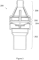
- FIG. 3 there is shown a further example connector 200. Any of the description of the connector 100 in Figure 1 may equally apply to connector 200 and will not be repeated for brevity.
- the connector 200 has a modified outlet formation and may allow greater throughflow of water/liquid.
- the bodies of the connectors of Figures 1 and 3 may be provided as a single/unitary member to which the valve structure 142 may be applied to as to provide the connector assembly.
- the connectors may be formed of a plurality of component parts which may be fused/welded together or otherwise joined using adhesive. Friction welding could be used to provide a suitable unitary body. In other examples, the component parts could be threaded and joined together as an assembly, rather than a unitary member.
- Figure 3 shows an example of the different component parts that may be used to form the connector body, comprising: a lower component 202 comprising the lower chamber wall, floor and outlet connector; a first intermediate component 204 comprising an intermediate chamber wall portion and the upper chamber floor or lower chamber ceiling; a second intermediate component 205 comprising an upper chamber wall portion and any ribs for supporting the valve assembly 142; and, an upper component 206 comprising the upper chamber wall, the connecting arms and inlet connector.
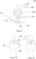
- FIG. 4 there is shown an embodiment of the strut 130 and/or intermediate component 205 in which the strut 130 has a retaining formation 208 for a liquid/moisture sensor to be described below.
- the retaining formation in this example takes the form of a partial enclosure or wall in which a sensor or sensor mounting component can be inserted.
- the wall is shaped to form an opening 210 by which a sensor can be mounted in the upper chamber.
- FIG. 5 there is shown a sensor mounting component 212 located in the opening 210 of the retaining formation 208.
- the sensor mounting component 212 comprises a wedge-like body having one or more through-bores or open-ended recesses 214. In this example, a pair of through-bores 214 are provided.
- the body of component 212 is received in the opening with a friction fit or a clip/snap fit.
- the mounting component 212 and the recesses therein allow for accurate sensor positioning.
- the mounting component may be formed of two opposing parts or halves, which are brought together to trap one or more sensing element there-between.
- the opposing parts may each be shaped to provide a portion of the through-bore(s) or other retaining formation once brought together.
- the sensor mounting component 212 may be referred to as a mounting clip.
- An embedded sensing prong/element design is enabled by the above arrangement.
- one or more sensor element 216 is mounted via the mounting component 212 such that it is suspended from the strut 130.
- the one or more sensor element is held in the mounting component 212, e.g. in the through-bore(s) 214 thereof.
- a pair of sensor elements 216 are mounted to the retaining formation 208 in this example.
- The/each sensor element 216 takes the form of one or more conductive element, e.g. a conductive prong in this example.
- The/each prong may be provided by a rigid prong member or an exposed end of a conductive wire.
- The/each prong 216 may comprise a wire/conductor member contained within an insulating sleeve/sheath 218, e.g. in the form of a conventional wire.
- the insulating sleeve(s) 218 may extend through the mounting component and may extend to a sensor device 220.
- the sensor element(s) 216 is/are connected to the sensor device 220.
- The/each sensor element 216 is mounted such that it is held/suspended above the valve member 145, e.g. a small distance above the valve member.
- the sensor element may be held within the middle chamber 177 of height H, e.g. spaced form the valve member 145 by a height less than the height of water required to open the valve.
- the spacing between the/each sensor element 216, e.g. its end, and the valve member may be less than 10mm and typically less than 8mm or 6mm. A spacing of greater than 1mm or 2mm may be desirable, e.g. to avoid overly sensitive water detection or inadvertent contact with the valve member 145 itself.
- a spacing in the order of 3-5 mm has been found suitable to detect the presence of water prior to opening of the valve but avoiding detection of an insignificant amount of water, e.g. such as a single drop.
- the sensor device 220 comprises an electrical/electronic water/moisture detector.
- the sensor device 220 monitors the resistance between the pair of conductive sensor elements 216. Whilst an air gap is present, the resistance between the elements 216 will be high enough to prevent electrical conduction therebetween. When the ends contact water, the resistance will decrease significantly, allowing electrical current to flow, which can be detected by sensor device 220.
- the sensor device 220 may apply an electrical potential difference across the sensor elements 216.
- the sensor device 220 Upon sensing of water in the connector 100, the sensor device 220 outputs a corresponding detection signal.
- the signal may be output as an electrical signal to monitoring equipment, e.g. via a wired or wireless connection.
- a wireless signal 222 is depicted in Figure 6 , which may comprise a Bluetooth (RTM) signal, Wi-Fi (RTM) signal or using another suitable wireless communication signal/standard.
- the sensor device 220 may comprise suitable output/transmission circuitry.
- the signal may comprise a visual or audible alert signal output by an output device of the sensor device itself.
- a suitable output device may comprise a speaker, light emitting diode or other equivalent device.
- a volt-free contact alarm may be implemented according to examples of the invention.
- the sensor device 220 may be mounted on the connector itself, e.g. rigidly mounted on a wall of the connector 100, 200 (such as an external wall of the connector), or else removably mounted using a releasable mounting.
- tundish connector different valve types may be used, such as a duckbill or trap door valve.
- a sensor of the type described herein may be mounted on a bespoke rib or else from the arm 125.
- the sensor could be mounted beneath the floor 170 and the sensing conductors/prongs could extend into the middle chamber 177 to sense a pool of water forming on the valve member 145 or flowing through the valve when open.
- the monitoring device 224 may be a conventional monitoring device or alarm box as may be mounted in domestic or commercial premises, e.g. for monitoring a boiler or central heating system. Most current units of this type can receive wireless signal inputs such as the output of sensor device 220. However a wired connection could be used if necessary.
- the sensor device 220 may communication with a local monitoring device/unit 224 as shown in Figure 7A .
- FIG. 7B shows another example in which a monitoring device 224 could itself be provided with water detection functionality hard-wired into the unit 224, e.g. by the sensing elements 216, 218 depending from the monitoring unit 224 itself.
- the monitoring unit could be provided with the logic/control aspect of the sensor device 220.
- the monitoring device may comprise a boiler monitoring or control unit, which may report and/or control further aspects of hot water system operation.
- the senor device 220 could have a longer/wider range communication capability and could communicate with a remote monitoring facility or a mobile communication device of an owner, operator or monitoring user. However it is envisaged that such communication/reporting operations will be performed by local monitoring unit 224, which may handle a number of other monitoring roles in addition to that of the water sensing for connector 100, 200.
- the sensing arrangement described herein is advantageous since it can provide an indication of connector valve operation, e.g. a leak or discharge from a hot water system, when no-one is present to witness the event.
- the sensor device 220 can output different signals for different types of fluid leak/discharge or different connector valve operation.
- the sensor device and/or monitoring unit 224 may be provided with one or more modules of computer readable code (e.g. monitoring/diagnosis algorithms) for identification of different potential faults or fault-indicating scenarios.
- different alert states or alert outputs may be output to indicate a severity or type of problem. This can be beneficial in allowing an operator, user or central monitoring facility in determining how to react to the sensed scenario.
- a slow drip of water may collect in the connector interior and may trigger the sensor device 220 briefly before the valve opens to discharge the water. A continued slow drip will take seconds, minutes or hours to amass enough water to trigger the detection of water by the sensor device again.
- one alert state that can be identified concerns an intermittent water detection of relatively short-lived duration.
- This may be identified as a possible minor leak, e.g. from a boiler discharge valve.
- An intermittent alert state may be reported.
- Suitable time thresholds of the intermittency/frequency of water detection may be used to determine the severity of such a leak and the urgency of any maintenance work to resolve the leak.
- An initial warning level may be set for such a detected scenario, which may be advanced to a higher alert or urgency level for more frequent intermittent water detection.
- a second alert state may comprise detection of a more prolonged water discharge but at a frequency of hours or days. For example, if the internal pressure within a boiler exceeds its threshold upon heating of water in the system, it may cause a discharge of a medium volume of liquid over a relatively short time period, such as a single discharge of 1-3 litres of water. This would cause a prolonged opening of the valve and associated water detection by the sensor device 220.
- this type of alert is repeated at intervals associated with boiler use, e.g. daily, twice daily or other suitable intervals, then it may be indicative of a pressure instability in the boiler. If undiagnosed, this can be problematic since the discharge will cause a boiler pressure to drop after use and may fall below an acceptable boiler pressure. An uninformed user may attempt to top up the boiler pressure to restart the boiler, thereby repeating the boiler discharge cycle upon heating and thus the problem can be exacerbated over time.
- the potential fault can be readily identified.
- a suitable service/maintenance appointment can be scheduled with the potential fault diagnosed in advance.
- a similar scenario could arise due to a constant trickle or drip only whilst the heating of the hot water system is active. Additionally or alternatively, this could be identified as a leaking boiler or hot water system discharge valve.
- a further alert state may be generated when a prolonged discharge through the connector is sensed, e.g. of 5, 10, 20 litres of more. This may be equated to a mass discharge from the hot water system that requires urgent attention. This type of alert may carry a higher or highest priority level since it is indicative of a serious fault that will prevent use of the hot water system.
- Monitoring of the frequency and/or duration of triggering of sensor may thus provide additional insight.
- This additional insight is made possible in part by the sensing of a pool of water collecting in the connector causing opening of the valve. Thus a rate/type of discharge can be determined.
- User controls may be provided to mute or ignore an alert generated by the system, e.g. upon being acknowledged by the user. Such functionality maybe useful for low priority, ongoing alerts.
- alert states Whilst a plurality, e.g. at least two, three, or four, different alert states are discussed above, it is possible that identification of further alert states could be implemented based on frequency, duration of triggering and/or one or more further parameter.
- One or more further sensor or sensor type could be used in conjunction with the sensor device 220.
- a temperature sensor may be provided in the connector in addition to, or instead of, the water sensor.
- the specific sensing elements 216 described above could be supplemented with, or replaced by, a temperature sensor.
- the temperature of a discharge from a hot water system and/or boiler can be monitored to provide further insight into the discharge scenario.
- a slow, intermittent, or medium discharge at elevated temperature can be diagnosed as a different fault to cold discharge. The latter situation will confirm whether it is the elevated temperature and/or pressure during operation that is leading to the discharge.
- an elevated temperature discharge above a threshold temperature may be used to determine a serious failure of the system.
- a discharge at a temperature above a higher safety temperature threshold for the hot water system implies that one or more hot water system safety valve or control measure has failed.
- a temperature above 90°C or 95°C for example should not occur unless a serious failure has arisen.
- one or more temperature thresholds may be used as an alert or diagnosis parameter according to aspects of the invention.
- the temperature sensor could be held in the connector anywhere it is likely be fluid washed by water flowing through the connector, subject to fluid dynamic considerations. In some examples, the temperature sensor could be suspended in a manner similar to the water sensors described herein.
- a combined water and temperature sensing arrangement is also anticipated, in which the conductors for sensing the presence of liquid are provided on a common support, which in this example takes the form of a printed circuit board.
- the support can thus be mounted as required in the connector such that the conductor ends are suspended above the valve member 145 so as to be in contact with a pool of liquid forming on the valve member, or e stream of liquid flowing through the device in the event that the valve member is open.
- the conductors would thus replace the use of the prongs 216 described above.
- the common support may be suspended from a strut 130, e.g. via a retaining formation 208, or else may be otherwise affixed to the interior of the connector as required.
- a temperature sensor can also be mounted on the same board.
- the conductors and temperature sensor may be mounted on the same or opposing sides of the common support.
- sensing components could individually be provided in such an arrangement without the other. Additional, or alternative sensing components could also be considered.
- the senor may comprise a valve actuation sensor, e.g. arranged to sense operation of the valve from a closed to an open condition, e.g. including the duration of valve operation.
- a valve actuation sensor e.g. arranged to sense operation of the valve from a closed to an open condition, e.g. including the duration of valve operation.
- an alert controller may be programmed to output a plurality of different types of alert signal in accordance with any of the parameters or scenarios disclosed above, either alone or in combination.
Landscapes
- Engineering & Computer Science (AREA)
- Health & Medical Sciences (AREA)
- Water Supply & Treatment (AREA)
- Public Health (AREA)
- Hydrology & Water Resources (AREA)
- Life Sciences & Earth Sciences (AREA)
- General Engineering & Computer Science (AREA)
- Mechanical Engineering (AREA)
- Physics & Mathematics (AREA)
- Combustion & Propulsion (AREA)
- Chemical & Material Sciences (AREA)
- Thermal Sciences (AREA)
- Environmental & Geological Engineering (AREA)
- Structural Engineering (AREA)
- General Physics & Mathematics (AREA)
- Automation & Control Theory (AREA)
- Business, Economics & Management (AREA)
- Emergency Management (AREA)
- Indication Of The Valve Opening Or Closing Status (AREA)
Claims (14)
- Verbinder (100) für ein Wassersystem, wobei der Verbinder (100) Folgendes umfasst:einen Einlass (105), einen Verbinderkörper und einen Auslass (120), die in Folge angeordnet sind, wobei der Verbinderkörper ein Zwischenbehälter mit offenen Seiten ist, der zwischen dem Einlass (105) und dem Auslass (120) einen offenen Luftspalt (107) aufweist, durch den bei Gebrauch Wasser fallen kann,gekennzeichnet durch einen Sensor (216), der im Inneren des Verbinderkörpers zwischen dem Einlass (105) und dem Auslass (120) montiert ist, um das Vorhandensein von Wasser in dem Verbinderkörper zu detektieren, wobei der Sensor (216) dazu konfiguriert ist, als Reaktion auf Erfassen von Wasser in dem Verbinderkörper ein Detektionssignal auszugeben.
- Verbinder (100) nach Anspruch 1, wobei der Verbinderkörper eine innere Bodenformation (170) zwischen dem Einlass (105) und dem Auslass (120) unterhalb des offenen Luftspalts (107) umfasst, wobei die Bodenformation (170) so angeordnet ist, dass sie das Innere des Verbinderkörpers in einen oberen (162) und unteren (182) inneren Kammerabschnitt unterteilt.
- Verbinder (100) nach Anspruch 2, wobei die innere Bodenformation (170) ein Rückschlagventil (142) umfasst und der Sensor (216) so angeordnet ist, dass er das Vorhandensein von Wasser auf oder über der inneren Bodenformation (170) erfasst.
- Verbinder (100) nach Anspruch 3, wobei der Sensor (216) über der inneren Bodenformation (170) aufgehängt ist.
- Verbinder (100) nach Anspruch 3 oder 4, wobei der Sensor (216) so angeordnet ist, dass es das Vorhandensein einer sich an dem Rückschlagventil (142) bildenden Wasserpfütze erfasst.
- Verbinder (100) nach einem der vorhergehenden Ansprüche, wobei der Sensor (216) einen Feuchtigkeitssensor und/oder einen Temperatursensor umfasst.
- Verbinder (100) nach Anspruch 6, wobei der Feuchtigkeitssensor und der Temperatursensor auf einem gemeinsamen Träger montiert sind.
- Verbinder (100) nach Anspruch 7, wobei der Träger eine Leiterplatte umfasst.
- Verbinder (100) nach einem der vorhergehenden Ansprüche, umfassend einen Ventilbetätigungssensor.
- Verbinder (100) nach einem der vorhergehenden Ansprüche, umfassend eine Überwachungsvorrichtung (224), die so angeordnet ist, dass sie die Ausgabe des oder jedes Sensors (216) überwacht und auf Grundlage der Ausgabe ein Warnsignal erzeugt.
- Verbinder nach Anspruch 10, wobei die Überwachungsvorrichtung (224) so angeordnet ist, dass sie eine Vielzahl von unterschiedlichen Warnsignalen entsprechend den Sensorausgaben ausgibt, die eines oder eine beliebige Kombination von Folgenden umfassen:einer Häufigkeit des Erfassens der Anwesenheit von Wasser,einer Dauer des Erfassens der Anwesenheit von Wasser und/odereinem oder mehreren Schwellenwerten für einen erfassten Zustand/Parameter.
- Verbinder (100) nach Anspruch 11, wobei die verschiedenen Warnsignale eine Vielzahl von unterschiedlichen Warnprioritätsstufen entsprechend einem oder mehreren erfassten Zuständen/Parametern umfassen.
- Wassersystemmonitor, umfassend den Verbinder (100) nach einem der Ansprüche 10 bis 12, wobei sich die Überwachungsvorrichtung (224) entfernt von dem Verbinder (100) befindet und in Signalkommunikation mit dem Sensor (216) steht.
- Wassersystemmonitor nach Anspruch 13, wobei die Überwachungsvorrichtung (224) einen Prozessor umfasst, der maschinenlesbare Anweisungen aufweist zum Verarbeiten empfangener Sensormesswerte, die auf das Vorhandensein von Wasser in dem Verbinder (100) hinweisen, und Ausgeben einer Vielzahl von unterschiedlichen Warnsignalen entsprechend einer Dauer und/oder Häufigkeit des erfassten Vorhandenseins von Wasser.
Applications Claiming Priority (2)
| Application Number | Priority Date | Filing Date | Title |
|---|---|---|---|
| GB1718199.1A GB2568065B (en) | 2017-11-02 | 2017-11-02 | Plumbing device |
| PCT/GB2018/053070 WO2019086836A1 (en) | 2017-11-02 | 2018-10-24 | Connector for a water system |
Publications (3)
| Publication Number | Publication Date |
|---|---|
| EP3704680A1 EP3704680A1 (de) | 2020-09-09 |
| EP3704680B1 true EP3704680B1 (de) | 2024-09-11 |
| EP3704680C0 EP3704680C0 (de) | 2024-09-11 |
Family
ID=60664672
Family Applications (1)
| Application Number | Title | Priority Date | Filing Date |
|---|---|---|---|
| EP18797032.2A Active EP3704680B1 (de) | 2017-11-02 | 2018-10-24 | Verbinder für ein wassersystem |
Country Status (6)
| Country | Link |
|---|---|
| US (1) | US11473786B2 (de) |
| EP (1) | EP3704680B1 (de) |
| AU (1) | AU2018361642B2 (de) |
| CA (1) | CA3081617A1 (de) |
| GB (1) | GB2568065B (de) |
| WO (1) | WO2019086836A1 (de) |
Families Citing this family (2)
| Publication number | Priority date | Publication date | Assignee | Title |
|---|---|---|---|---|
| GB2596506B (en) * | 2020-04-03 | 2024-05-29 | Altecnic Ltd | Tundishes |
| CN117188764A (zh) * | 2023-09-26 | 2023-12-08 | 远发新材料股份有限公司 | 一种快速拆装塑料模板阳角加固装置 |
Family Cites Families (10)
| Publication number | Priority date | Publication date | Assignee | Title |
|---|---|---|---|---|
| US6415816B1 (en) | 2000-08-31 | 2002-07-09 | Cherne Industries Incorporated | Air admittance valve assembly |
| DE202005002415U1 (de) * | 2005-02-14 | 2005-04-21 | Hans Sasserath & Co. Kg | Bauteilsatz zum modularen Erstellen einer Ablaufanordnung |
| US8172154B1 (en) * | 2007-02-22 | 2012-05-08 | Figley Donald A | Humidity monitoring and alarm system for unattended detection of building moisture management problems |
| US20110132474A1 (en) * | 2009-12-09 | 2011-06-09 | Utah State University | Back Flow Prevention System |
| DE202012103132U1 (de) | 2012-08-20 | 2013-11-22 | Hans Sasserath & Co. Kg | Ablaufanordnung für Wasserarmaturen |
| GB201513876D0 (en) * | 2015-08-05 | 2015-09-16 | Armstrong Russell W | Plumbing device |
| US10364559B2 (en) * | 2014-01-30 | 2019-07-30 | Russell Winston Armstrong | Plumbing device |
| GB2522634B (en) * | 2014-01-30 | 2016-04-27 | Winston Armstrong Russell | Plumbing connector having non-return valve |
| DE202015103322U1 (de) | 2015-06-24 | 2016-09-30 | Hans Sasserath Gmbh & Co. Kg | Vorsatzstück für Ablauftrichter |
| US10127790B2 (en) * | 2016-03-22 | 2018-11-13 | Watts Regulator Co. | Leak detector |
-
2017
- 2017-11-02 GB GB1718199.1A patent/GB2568065B/en active Active
-
2018
- 2018-10-24 US US16/761,076 patent/US11473786B2/en active Active
- 2018-10-24 CA CA3081617A patent/CA3081617A1/en active Pending
- 2018-10-24 WO PCT/GB2018/053070 patent/WO2019086836A1/en not_active Ceased
- 2018-10-24 EP EP18797032.2A patent/EP3704680B1/de active Active
- 2018-10-24 AU AU2018361642A patent/AU2018361642B2/en active Active
Also Published As
| Publication number | Publication date |
|---|---|
| US11473786B2 (en) | 2022-10-18 |
| AU2018361642B2 (en) | 2024-06-13 |
| CA3081617A1 (en) | 2019-05-09 |
| EP3704680A1 (de) | 2020-09-09 |
| GB2568065A (en) | 2019-05-08 |
| AU2018361642A1 (en) | 2020-06-18 |
| WO2019086836A1 (en) | 2019-05-09 |
| GB2568065B (en) | 2022-03-09 |
| GB201718199D0 (en) | 2017-12-20 |
| EP3704680C0 (de) | 2024-09-11 |
| US20210010682A1 (en) | 2021-01-14 |
Similar Documents
| Publication | Publication Date | Title |
|---|---|---|
| US10590640B2 (en) | Automated plumbing system sensor warning system and method | |
| US8013749B2 (en) | Fluid detection and containment apparatus | |
| US8643497B2 (en) | Integral fluid detection and containment apparatus | |
| US20150376874A1 (en) | Water leak detection, prevention and water conservation systems and methods | |
| KR101682226B1 (ko) | 오배수펌프 패키지 시스템 | |
| US10535246B2 (en) | Sewer alarm apparatus having a probe | |
| EP3704680B1 (de) | Verbinder für ein wassersystem | |
| CA3023942A1 (en) | Leak detection sensor assemblies for water heaters | |
| EP2363540A2 (de) | Automatische Duschwanne oder Feuchtraumabfluss | |
| EP3102745B1 (de) | Klempnervorrichtung | |
| KR101143481B1 (ko) | 수돗물 누수 경보장치 | |
| KR101756520B1 (ko) | 자동 점검 유량조절장치 | |
| US20160328956A1 (en) | Networked leak and overflow detection, control and prevention system | |
| US6895990B1 (en) | Water heater fail safe apparatus | |
| US20060033629A1 (en) | Over flow sensor | |
| JP3794159B2 (ja) | スプリンクラ設備を利用した漏水・停滞水の報知システム | |
| JP6727537B2 (ja) | 貯湯式電気温水器 | |
| RS60757B1 (sr) | Cevni kontejner sa radio detektorom povratnog toka i uređajem za skladištenje električne energije | |
| US20230351880A1 (en) | Liquid level sensor and protective cover | |
| JP6914294B2 (ja) | 排水管詰まり監視装置及び排水管詰まり監視システム | |
| CN121253070A (zh) | 基于多种传感器的净水器漏水检测方法、系统及存储介质 | |
| WO2013144800A2 (en) | System for detecting and/or controlling a water loss in a water supply network | |
| KR20100007416U (ko) | 파이프라인가스검지부 |
Legal Events
| Date | Code | Title | Description |
|---|---|---|---|
| STAA | Information on the status of an ep patent application or granted ep patent |
Free format text: STATUS: UNKNOWN |
|
| STAA | Information on the status of an ep patent application or granted ep patent |
Free format text: STATUS: THE INTERNATIONAL PUBLICATION HAS BEEN MADE |
|
| PUAI | Public reference made under article 153(3) epc to a published international application that has entered the european phase |
Free format text: ORIGINAL CODE: 0009012 |
|
| STAA | Information on the status of an ep patent application or granted ep patent |
Free format text: STATUS: REQUEST FOR EXAMINATION WAS MADE |
|
| 17P | Request for examination filed |
Effective date: 20200602 |
|
| AK | Designated contracting states |
Kind code of ref document: A1 Designated state(s): AL AT BE BG CH CY CZ DE DK EE ES FI FR GB GR HR HU IE IS IT LI LT LU LV MC MK MT NL NO PL PT RO RS SE SI SK SM TR |
|
| AX | Request for extension of the european patent |
Extension state: BA ME |
|
| DAV | Request for validation of the european patent (deleted) | ||
| DAX | Request for extension of the european patent (deleted) | ||
| STAA | Information on the status of an ep patent application or granted ep patent |
Free format text: STATUS: EXAMINATION IS IN PROGRESS |
|
| 17Q | First examination report despatched |
Effective date: 20211222 |
|
| RIN1 | Information on inventor provided before grant (corrected) |
Inventor name: ARMSTRONG, RUSSELL WINSTON |
|
| REG | Reference to a national code |
Ref country code: DE Ref legal event code: R079 Free format text: PREVIOUS MAIN CLASS: G08B0021180000 Ipc: G08B0021200000 Ref document number: 602018074298 Country of ref document: DE |
|
| GRAP | Despatch of communication of intention to grant a patent |
Free format text: ORIGINAL CODE: EPIDOSNIGR1 |
|
| STAA | Information on the status of an ep patent application or granted ep patent |
Free format text: STATUS: GRANT OF PATENT IS INTENDED |
|
| RIC1 | Information provided on ipc code assigned before grant |
Ipc: F24D 19/08 20060101ALN20240315BHEP Ipc: F16K 37/00 20060101ALI20240315BHEP Ipc: E03B 7/07 20060101ALI20240315BHEP Ipc: G08B 21/20 20060101AFI20240315BHEP |
|
| INTG | Intention to grant announced |
Effective date: 20240417 |
|
| GRAS | Grant fee paid |
Free format text: ORIGINAL CODE: EPIDOSNIGR3 |
|
| GRAA | (expected) grant |
Free format text: ORIGINAL CODE: 0009210 |
|
| STAA | Information on the status of an ep patent application or granted ep patent |
Free format text: STATUS: THE PATENT HAS BEEN GRANTED |
|
| AK | Designated contracting states |
Kind code of ref document: B1 Designated state(s): AL AT BE BG CH CY CZ DE DK EE ES FI FR GB GR HR HU IE IS IT LI LT LU LV MC MK MT NL NO PL PT RO RS SE SI SK SM TR |
|
| REG | Reference to a national code |
Ref country code: GB Ref legal event code: FG4D |
|
| REG | Reference to a national code |
Ref country code: CH Ref legal event code: EP |
|
| REG | Reference to a national code |
Ref country code: DE Ref legal event code: R096 Ref document number: 602018074298 Country of ref document: DE |
|
| REG | Reference to a national code |
Ref country code: IE Ref legal event code: FG4D |
|
| U01 | Request for unitary effect filed |
Effective date: 20241004 |
|
| U07 | Unitary effect registered |
Designated state(s): AT BE BG DE DK EE FI FR IT LT LU LV MT NL PT RO SE SI Effective date: 20241028 |
|
| PG25 | Lapsed in a contracting state [announced via postgrant information from national office to epo] |
Ref country code: NO Free format text: LAPSE BECAUSE OF FAILURE TO SUBMIT A TRANSLATION OF THE DESCRIPTION OR TO PAY THE FEE WITHIN THE PRESCRIBED TIME-LIMIT Effective date: 20241211 |
|
| PG25 | Lapsed in a contracting state [announced via postgrant information from national office to epo] |
Ref country code: GR Free format text: LAPSE BECAUSE OF FAILURE TO SUBMIT A TRANSLATION OF THE DESCRIPTION OR TO PAY THE FEE WITHIN THE PRESCRIBED TIME-LIMIT Effective date: 20241212 |
|
| PG25 | Lapsed in a contracting state [announced via postgrant information from national office to epo] |
Ref country code: HR Free format text: LAPSE BECAUSE OF FAILURE TO SUBMIT A TRANSLATION OF THE DESCRIPTION OR TO PAY THE FEE WITHIN THE PRESCRIBED TIME-LIMIT Effective date: 20240911 |
|
| PG25 | Lapsed in a contracting state [announced via postgrant information from national office to epo] |
Ref country code: RS Free format text: LAPSE BECAUSE OF FAILURE TO SUBMIT A TRANSLATION OF THE DESCRIPTION OR TO PAY THE FEE WITHIN THE PRESCRIBED TIME-LIMIT Effective date: 20241211 Ref country code: ES Free format text: LAPSE BECAUSE OF FAILURE TO SUBMIT A TRANSLATION OF THE DESCRIPTION OR TO PAY THE FEE WITHIN THE PRESCRIBED TIME-LIMIT Effective date: 20240911 |
|
| PG25 | Lapsed in a contracting state [announced via postgrant information from national office to epo] |
Ref country code: RS Free format text: LAPSE BECAUSE OF FAILURE TO SUBMIT A TRANSLATION OF THE DESCRIPTION OR TO PAY THE FEE WITHIN THE PRESCRIBED TIME-LIMIT Effective date: 20241211 Ref country code: NO Free format text: LAPSE BECAUSE OF FAILURE TO SUBMIT A TRANSLATION OF THE DESCRIPTION OR TO PAY THE FEE WITHIN THE PRESCRIBED TIME-LIMIT Effective date: 20241211 Ref country code: HR Free format text: LAPSE BECAUSE OF FAILURE TO SUBMIT A TRANSLATION OF THE DESCRIPTION OR TO PAY THE FEE WITHIN THE PRESCRIBED TIME-LIMIT Effective date: 20240911 Ref country code: GR Free format text: LAPSE BECAUSE OF FAILURE TO SUBMIT A TRANSLATION OF THE DESCRIPTION OR TO PAY THE FEE WITHIN THE PRESCRIBED TIME-LIMIT Effective date: 20241212 Ref country code: ES Free format text: LAPSE BECAUSE OF FAILURE TO SUBMIT A TRANSLATION OF THE DESCRIPTION OR TO PAY THE FEE WITHIN THE PRESCRIBED TIME-LIMIT Effective date: 20240911 |
|
| U20 | Renewal fee for the european patent with unitary effect paid |
Year of fee payment: 7 Effective date: 20250111 |
|
| PG25 | Lapsed in a contracting state [announced via postgrant information from national office to epo] |
Ref country code: IS Free format text: LAPSE BECAUSE OF FAILURE TO SUBMIT A TRANSLATION OF THE DESCRIPTION OR TO PAY THE FEE WITHIN THE PRESCRIBED TIME-LIMIT Effective date: 20250111 |
|
| PG25 | Lapsed in a contracting state [announced via postgrant information from national office to epo] |
Ref country code: SM Free format text: LAPSE BECAUSE OF FAILURE TO SUBMIT A TRANSLATION OF THE DESCRIPTION OR TO PAY THE FEE WITHIN THE PRESCRIBED TIME-LIMIT Effective date: 20240911 |
|
| PG25 | Lapsed in a contracting state [announced via postgrant information from national office to epo] |
Ref country code: PL Free format text: LAPSE BECAUSE OF FAILURE TO SUBMIT A TRANSLATION OF THE DESCRIPTION OR TO PAY THE FEE WITHIN THE PRESCRIBED TIME-LIMIT Effective date: 20240911 Ref country code: CZ Free format text: LAPSE BECAUSE OF FAILURE TO SUBMIT A TRANSLATION OF THE DESCRIPTION OR TO PAY THE FEE WITHIN THE PRESCRIBED TIME-LIMIT Effective date: 20240911 |
|
| PG25 | Lapsed in a contracting state [announced via postgrant information from national office to epo] |
Ref country code: SK Free format text: LAPSE BECAUSE OF FAILURE TO SUBMIT A TRANSLATION OF THE DESCRIPTION OR TO PAY THE FEE WITHIN THE PRESCRIBED TIME-LIMIT Effective date: 20240911 |
|
| REG | Reference to a national code |
Ref country code: CH Ref legal event code: PL |
|
| PG25 | Lapsed in a contracting state [announced via postgrant information from national office to epo] |
Ref country code: MC Free format text: LAPSE BECAUSE OF FAILURE TO SUBMIT A TRANSLATION OF THE DESCRIPTION OR TO PAY THE FEE WITHIN THE PRESCRIBED TIME-LIMIT Effective date: 20240911 |
|
| PLBE | No opposition filed within time limit |
Free format text: ORIGINAL CODE: 0009261 |
|
| STAA | Information on the status of an ep patent application or granted ep patent |
Free format text: STATUS: NO OPPOSITION FILED WITHIN TIME LIMIT |
|
| PG25 | Lapsed in a contracting state [announced via postgrant information from national office to epo] |
Ref country code: CH Free format text: LAPSE BECAUSE OF NON-PAYMENT OF DUE FEES Effective date: 20241031 |
|
| 26N | No opposition filed |
Effective date: 20250612 |
|
| PG25 | Lapsed in a contracting state [announced via postgrant information from national office to epo] |
Ref country code: IE Free format text: LAPSE BECAUSE OF NON-PAYMENT OF DUE FEES Effective date: 20241024 |
|
| U21 | Renewal fee for the european patent with unitary effect paid with additional fee |
Year of fee payment: 8 Effective date: 20251114 |
|
| PGFP | Annual fee paid to national office [announced via postgrant information from national office to epo] |
Ref country code: GB Payment date: 20251114 Year of fee payment: 8 |