EP3704396B1 - Absorbeur d'énergie pour siège d'aéronef - Google Patents
Absorbeur d'énergie pour siège d'aéronef Download PDFInfo
- Publication number
- EP3704396B1 EP3704396B1 EP18789140.3A EP18789140A EP3704396B1 EP 3704396 B1 EP3704396 B1 EP 3704396B1 EP 18789140 A EP18789140 A EP 18789140A EP 3704396 B1 EP3704396 B1 EP 3704396B1
- Authority
- EP
- European Patent Office
- Prior art keywords
- anchoring point
- energy
- energy absorber
- energy absorption
- seat
- Prior art date
- Legal status (The legal status is an assumption and is not a legal conclusion. Google has not performed a legal analysis and makes no representation as to the accuracy of the status listed.)
- Active
Links
- 239000006096 absorbing agent Substances 0.000 title claims description 38
- 238000010521 absorption reaction Methods 0.000 claims description 38
- 238000004873 anchoring Methods 0.000 claims description 14
- 239000000463 material Substances 0.000 claims description 7
- 239000007769 metal material Substances 0.000 claims description 3
- 229910001220 stainless steel Inorganic materials 0.000 claims description 3
- 239000010935 stainless steel Substances 0.000 claims description 3
- 238000006073 displacement reaction Methods 0.000 claims 1
- 239000002184 metal Substances 0.000 description 5
- 229910003460 diamond Inorganic materials 0.000 description 3
- 239000010432 diamond Substances 0.000 description 3
- 230000001681 protective effect Effects 0.000 description 2
- 230000002745 absorbent Effects 0.000 description 1
- 239000002250 absorbent Substances 0.000 description 1
- 238000003698 laser cutting Methods 0.000 description 1
- 230000035939 shock Effects 0.000 description 1
- 239000007787 solid Substances 0.000 description 1
Images


Classifications
-
- F—MECHANICAL ENGINEERING; LIGHTING; HEATING; WEAPONS; BLASTING
- F16—ENGINEERING ELEMENTS AND UNITS; GENERAL MEASURES FOR PRODUCING AND MAINTAINING EFFECTIVE FUNCTIONING OF MACHINES OR INSTALLATIONS; THERMAL INSULATION IN GENERAL
- F16F—SPRINGS; SHOCK-ABSORBERS; MEANS FOR DAMPING VIBRATION
- F16F7/00—Vibration-dampers; Shock-absorbers
- F16F7/12—Vibration-dampers; Shock-absorbers using plastic deformation of members
- F16F7/123—Deformation involving a bending action, e.g. strap moving through multiple rollers, folding of members
-
- F—MECHANICAL ENGINEERING; LIGHTING; HEATING; WEAPONS; BLASTING
- F16—ENGINEERING ELEMENTS AND UNITS; GENERAL MEASURES FOR PRODUCING AND MAINTAINING EFFECTIVE FUNCTIONING OF MACHINES OR INSTALLATIONS; THERMAL INSULATION IN GENERAL
- F16F—SPRINGS; SHOCK-ABSORBERS; MEANS FOR DAMPING VIBRATION
- F16F1/00—Springs
- F16F1/02—Springs made of steel or other material having low internal friction; Wound, torsion, leaf, cup, ring or the like springs, the material of the spring not being relevant
- F16F1/04—Wound springs
- F16F1/12—Attachments or mountings
- F16F1/121—Attachments or mountings adjustable, e.g. to modify spring characteristics
-
- F—MECHANICAL ENGINEERING; LIGHTING; HEATING; WEAPONS; BLASTING
- F16—ENGINEERING ELEMENTS AND UNITS; GENERAL MEASURES FOR PRODUCING AND MAINTAINING EFFECTIVE FUNCTIONING OF MACHINES OR INSTALLATIONS; THERMAL INSULATION IN GENERAL
- F16F—SPRINGS; SHOCK-ABSORBERS; MEANS FOR DAMPING VIBRATION
- F16F1/00—Springs
- F16F1/02—Springs made of steel or other material having low internal friction; Wound, torsion, leaf, cup, ring or the like springs, the material of the spring not being relevant
- F16F1/04—Wound springs
- F16F1/12—Attachments or mountings
- F16F1/128—Attachments or mountings with motion-limiting means, e.g. with a full-length guide element or ball joint connections; with protective outer cover
-
- F—MECHANICAL ENGINEERING; LIGHTING; HEATING; WEAPONS; BLASTING
- F16—ENGINEERING ELEMENTS AND UNITS; GENERAL MEASURES FOR PRODUCING AND MAINTAINING EFFECTIVE FUNCTIONING OF MACHINES OR INSTALLATIONS; THERMAL INSULATION IN GENERAL
- F16F—SPRINGS; SHOCK-ABSORBERS; MEANS FOR DAMPING VIBRATION
- F16F3/00—Spring units consisting of several springs, e.g. for obtaining a desired spring characteristic
- F16F3/02—Spring units consisting of several springs, e.g. for obtaining a desired spring characteristic with springs made of steel or of other material having low internal friction
- F16F3/023—Spring units consisting of several springs, e.g. for obtaining a desired spring characteristic with springs made of steel or of other material having low internal friction composed only of leaf springs
-
- F—MECHANICAL ENGINEERING; LIGHTING; HEATING; WEAPONS; BLASTING
- F16—ENGINEERING ELEMENTS AND UNITS; GENERAL MEASURES FOR PRODUCING AND MAINTAINING EFFECTIVE FUNCTIONING OF MACHINES OR INSTALLATIONS; THERMAL INSULATION IN GENERAL
- F16F—SPRINGS; SHOCK-ABSORBERS; MEANS FOR DAMPING VIBRATION
- F16F2224/00—Materials; Material properties
- F16F2224/02—Materials; Material properties solids
- F16F2224/0208—Alloys
Definitions
- the present invention relates to an energy absorber for an aircraft seat.
- the invention finds a particularly advantageous, but not exclusive, application with helicopter seats of the single-seater or multi-seater type.
- the helicopter seat may be a pilot seat or a passenger seat.
- the document EP2113677 describes an energy absorber provided with an absorbing portion extending between a first and a second anchor point.
- the absorbent portion comprises at least one solid filiform element deforming elastically during a tensile stress below a predetermined threshold and plastically during a tensile stress above said predetermined threshold.
- the filiform element(s) are provided with a succession of straight segments and circular arc segments connecting two successive straight segments. The invention aims to improve the control of the elongation of such a device. ⁇ A >
- the document DE102006023688 describes a mechanical energy absorber intended to extend in the direction of a stretching axis during a deformation phase.
- the document US5961146 describes a shock absorber comprising a first support intended to be fixed to a steering column and a second support formed in one piece with a body of a vehicle.
- the document FR2695177 describes an energy-absorbing device with high elongation capacity formed by a longitudinal metal element comprising, on the one hand, a succession of meshes capable of being plastically deformed in a direction substantially perpendicular to their initial orientation to open gradually depending on the tensile force applied and, on the other hand, hooking means to a fixed anchor point and to a mobile anchor point.
- the document US2005/012319 discloses a load limiting device for a vehicle occupant restraint device.
- the load limiting device includes a longitudinal load limiting member connected between the vehicle occupant restraint and an anchorage point such as a vehicle seat or a structural part of the vehicle.
- the energy absorbing element has an asymmetrical configuration with respect to a traction axis passing through the first anchor point and the second anchor point.
- the energy absorption zone comprises at least one part presenting longitudinally a succession of rows of junction portions, each row comprising two junction portions.
- the strands of the energy absorption zone have various dimensions and/or orientations and/or types of materials so as to adapt to an occupant's morphology.
- said energy absorber comprises a plurality of energy absorbing elements stacked on top of each other and configured to activate in cascade according to an occupant's morphology.
- the energy absorbing element is made of a metallic material, in particular stainless steel.
- the invention also relates to an aircraft seat, in particular a helicopter seat, characterized in that it comprises an energy absorber as defined above.
- the energy absorber comprises a first anchor point cooperating with a pin secured to a support leg and a second anchor point cooperating with a pin secured to the rear edge of the seat structure.
- the pin integral with the rear edge of the seat structure is inserted inside a groove provided in an upright of the corresponding support foot, said groove being able to guide a movement of the rear edge of the seat structure when a tensile force is applied between the first anchor point and the second anchor point.
- said aircraft seat comprises a protective cover for the energy absorber.
- the figures 1a, 1b and 3 show an energy absorber 10 for an aircraft seat, in particular for a helicopter seat, comprising at least one energy absorbing element 11.
- This element 11 comprises a first anchor point 12 and a second anchor point 13, as well as an energy absorption zone 14 extending between the first anchor point 12 and the second anchor point 13.
- This energy absorption zone 14 is capable of stretching when a tensile force is applied between the first anchor point 12 and the second anchor point 13.
- the energy absorption zone 14 has a mesh structure comprising a plurality of strands 16 interconnected by junction portions 17, a strand 16 extending between two successive junction portions 17.
- at least one junction portion 17 provides a junction between at least three strands 16 of said energy absorption zone 14.
- the strands 16 are advantageously straight.
- the strands 17 have an orientation inclined with respect to the horizontal in the unstressed state, so that the meshes of the zone 14 have a diamond shape.
- the inclination of the strands 17 can be adapted according to the application.
- the strands 17 may have a horizontal orientation.
- the strands 17 may also have the same length or different lengths relative to each other.
- the energy absorbing element 11 has a symmetrical configuration with respect to a traction axis X passing through the first anchor point 12 and the second anchor point 13.
- the two parts P1, P2 located on either side of the traction axis X which have the same dimensions and the same angles.
- the energy absorption zone 14 comprises at least one part having longitudinally a regular alternation of a row having two junction portions 17 and of a row having a single junction portion 17.
- the energy absorption zone 14 comprises at least one part having longitudinally a regular alternation of a row having two junction portions 17 and of a row having a single junction portion 17.
- there is a longitudinal succession of rows R1-Rn a row R1 having two junction portions 17 then a row R2 having a single junction portion 17, then a row R3 having two junction portions 17 and so on following at least part of the absorption zone of energy 14, preferably along the entire energy absorption zone 14.
- the figure 2 shows a curve C1 of evolution of a stress as a function of a stretching of an energy absorber 10 of the symmetrical type during the application of a tensile force between the anchor points 12, 13.
- the curve C1 has a first phase Ph_1 of increasing the load, then an elongation phase Ph_2 in which the variation in stress is small so that the force undergone by the seat is controlled.
- Ph_3 phase the material deforms until it breaks.
- the energy absorbing element 11 has an asymmetrical configuration with respect to the traction axis X passing through the first anchor point 12 and the second anchor point 13. In this case, there is no no exact correspondence between the two parts P1', P2' located on either side of the traction axis X which do not have the same dimensions and/or not the same angles.
- the energy absorption zone 14 comprises at least one part presenting longitudinally a succession of transverse rows R1-Rn of junction portions 17.
- Each row R1-Rn comprises two junction portions 17.
- the intermediate rows each comprise a junction portion 17 connecting two strands 16 together and a junction portion 17 connecting four strands 16 together.
- the anchor points 12, 13 are offset relative to each other in a vertical direction D shown in broken lines on the figure 6a .
- the anchor points 12, 13 may be aligned relative to each other in this vertical direction D.
- the figure 4 shows curves C1', C2', C3' of the evolution of the stress as a function of the stretching of an asymmetrical energy absorber 10 during the application of a tensile force between the two anchoring points 12, 13.
- Each curve has a first phase Ph_1' of increased load, then an extended elongation phase Ph_2' in which the variation in stress is substantially constant so that the force undergone by the seat is controlled.
- Ph_3' phase the material deforms until it breaks.
- Curves C1', C2', and C3' have respectively been obtained for a single element 11, two elements 11, and three energy absorbing elements 11 stacked on top of each other. It is noted that the number of elements 11 makes it possible to adapt the level of the stresses undergone by the energy absorber 10.
- an energy absorbing element 11 therefore has a thickness comprised between 1 mm and 3 mm and preferably being approximately 1.5 mm (by “approximately” is meant a variation of plus or minus 10% around this value).
- the length of the element 11 is approximately 10 cm in the unstressed state, that is to say before stretching.
- the element 11 is preferably made of a metallic material, in particular stainless steel.
- the material as well as the dimensions, in particular the length of an energy absorbing element 11, can be adapted according to the application.
- An element 11 can be obtained by laser cutting a metal plate.
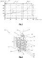
- Element 11 of the picture 1a can thus be made by cutting the outline in a metal plate and then making three vertical rows of holes 18 in staggered rows.
- the holes 18 of a given line are located between two holes 18 of an adjacent line.
- the holes 18 could for example take a diamond shape.
- Element 11 of the figure 1b can be made by cutting the outline in a metal plate and then making a vertical line of holes 18 having a rectangular shape.
- Element 11 of the picture 3 can be made by cutting the contour in a metal plate and then making two vertical rows of holes 18 staggered.
- the holes 18 of a given line are located between two holes 18 of the adjacent vertical row of holes 18.
- the holes 18 could for example take a diamond shape.
- the strands 16 of the energy absorption zone 14 can have various dimensions and/or orientations and/or types of material so as to adapt to an occupant's morphology.
- the mesh of the upper part of the element 11 comprises, in the unconstrained state, strands 16 having a horizontal orientation; while the mesh of the lower part comprises, in the unconstrained state, strands 16 having an orientation inclined with respect to a horizontal direction.
- a plurality of energy absorbing elements 11 are stacked on top of each other and configured to activate in cascade depending on an occupant's morphology.
- first anchoring points 12 of the superimposed elements 11 have holes 19 which coincide with each other and which are intended to cooperate with a fixed axis of the seat.
- second anchor point 13 of the first element 11 has a circular hole 20 to cooperate with an axis of the movable seat in the event of an impact causing the stretching of the element 11, as explained in more detail below.
- the following elements 11 comprise anchor points 13 constituted by oblong holes 21 having end edges offset longitudinally with respect to each other. The length of the oblong holes 21 increases as one moves away from the anchor point 13 of the first element 11.
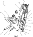
- the figure 7 shows a helicopter seat 22 comprising two support legs 23 provided with fasteners 24 for fixing to the rails of the aircraft.
- a seat structure 25 comprises a front edge 25.1 rotatably mounted relative to the support legs 23 and a rear edge 25.2 mounted suspended relative to the support legs 23 via at least one energy absorber 10.
- a first anchor point 12 of the energy absorber 10 cooperates with a pin 28 secured to a support foot 23 and a second anchor point 13 cooperates with a pin 29 secured to the rear edge 25.2 of the seat structure 25.
- the pin 29 integral with the rear edge 25.2 of the seat structure 25 is inserted inside a groove 30 formed in an upright 31 of the corresponding support foot 23.
- the groove 30 is able to guide a movement of the rear edge 25.2 of the seat structure 25 when a tensile force is applied between the anchor points 12, 13 during an impact.
- the seat structure 25 moves downwards following the stretching of the energy absorber 10 by rotating around the axis 28 integral with the support foot 23.
- the movement of the seat under the seat 22 is controlled thanks to the groove 30 which guides the axis 29 of the rear edge 25.2 connected to the anchor point 13 of the absorber 10, the first anchor point 12 fixed to the support foot 23 forming a frame being stationary.
- an energy absorber 10 is arranged on each side of the seat structure 25.
- a protective cover 35 of the energy absorber 10 is mounted on each upright 31 of the support legs 23.
- the seat 22 may also include a lumbar support 32 associated with an upper portion of the backrest 33 extending between the two support legs 23.
- a lumbar support 32 associated with an upper portion of the backrest 33 extending between the two support legs 23.
- the seat 22 comprises a connecting crosspiece between the two support legs 23 as well as a headrest.
Landscapes
- Engineering & Computer Science (AREA)
- General Engineering & Computer Science (AREA)
- Mechanical Engineering (AREA)
- Vibration Dampers (AREA)
- Aviation & Aerospace Engineering (AREA)
- Seats For Vehicles (AREA)
Description
- La présente invention porte sur un absorbeur d'énergie pour siège d'aéronef.
- L'invention trouve une application particulièrement avantageuse, mais non exclusive, avec les sièges d'hélicoptère de type monoplace ou multiplaces. Le siège d'hélicoptère pourra être un siège pilote ou un siège passager.
- Le document
EP2113677 décrit un absorbeur d'énergie muni d'une portion absorbante s'étendant entre un premier et un deuxième point d'ancrage. La portion absorbante comporte au moins un élément filiforme solide se déformant élastiquement lors d'une sollicitation en traction inférieure à un seuil prédéterminé et plastiquement lors d'une sollicitation en traction supérieure audit seuil prédéterminé. Le ou les éléments filiformes sont munis d'une succession de segments droits et de segments en arc de cercle reliant deux segments droits successifs. L'invention vise à améliorer le contrôle de l'allongement d'un tel dispositif. < A > - A cet effet, l'invention a pour objet un absorbeur d'énergie pour siège d'aéronef, notamment pour un siège d'hélicoptère, comportant au moins un élément d'absorption d'énergie ayant:
- un premier point d'ancrage et un deuxième point d'ancrage,
- une zone d'absorption d'énergie s'étendant entre le premier point d'ancrage et le deuxième point d'ancrage, ladite zone d'absorption d'énergie étant apte à s'étirer lors de l'application d'un effort de traction entre le premier point d'ancrage et le deuxième point d'ancrage,
- caractérisé en ce que la zone d'absorption d'énergie présente une structure maillée comportant une pluralité de brins reliés entre eux par des portions de jonction, et en ce qu'au moins une portion de jonction assure une jonction entre au moins trois brins de ladite zone d'absorption d'énergie.
- Le document
DE102006023688 décrit un absorbeur d'énergie mécanique destiné à s'étendre dans la direction d'un axe d'étirement lors d'une phase de déformation. - Le document
US5961146 décrit un amortisseur de chocs comprenant un premier support destiné à être fixé à une colonne de direction et un second support formé d'un seul tenant avec une carrosserie d'un véhicule. - Le document
FR2695177 - Le document
US2005/012319 décrit un dispositif de limitation de charge pour un dispositif de retenue d'occupants de véhicule. Le dispositif de limitation de charge comprend un élément longitudinal de limitation de charge connecté entre le dispositif de retenue des occupants du véhicule et un point d'ancrage tel qu'un siège de véhicule ou une partie structurelle du véhicule. - Selon l'invention, l'élément d'absorption d'énergie présente une configuration dissymétrique par rapport à un axe de traction passant par le premier point d'ancrage et le deuxième point d'ancrage.
- Selon une réalisation, la zone d'absorption d'énergie comporte au moins une partie présentant longitudinalement une succession de rangées de portions de jonction, chaque rangée comprenant deux portions de jonction.
- Selon une réalisation, les brins de la zone d'absorption d'énergie présentent des dimensions et/ou des orientations et/ou des types de matériaux variés de manière à s'adapter à une morphologie d'un occupant.
- Selon une réalisation, ledit absorbeur d'énergie comporte une pluralité d'éléments d'absorption d'énergie empilés les uns sur les autres et configurés pour s'activer en cascade en fonction d'une morphologie d'un occupant.
- Selon une réalisation, l'élément d'absorption d'énergie est réalisé dans un matériau métallique, notamment en acier inoxydable.
- L'invention a également pour objet un siège d'aéronef, notamment un siège d'hélicoptère, caractérisé en ce qu'il comporte un absorbeur d'énergie tel que précédemment défini.
- Selon une réalisation, ledit siège d'aéronef comporte:
- deux pieds de support munis d'attache de fixation à des rails de l'aéronef,
- une structure d'assise ayant un bord avant monté rotatif par rapport aux pieds de support et un bord arrière monté suspendu par rapport aux pieds de support par l'intermédiaire d'au moins un absorbeur d'énergie.
- Selon une réalisation, l'absorbeur d'énergie comporte un premier point d'ancrage coopérant avec un axe solidaire d'un pied de support et un deuxième point d'ancrage coopérant avec un axe solidaire du bord arrière de la structure d'assise.
- Selon une réalisation, l'axe solidaire du bord arrière de la structure d'assise est inséré à l'intérieur d'une rainure ménagée dans un montant du pied de support correspondant, ladite rainure étant apte à guider un déplacement du bord arrière de la structure d'assise lorsqu'un effort de traction est appliqué entre le premier point d'ancrage et le deuxième point d'ancrage.
- Selon une réalisation, ledit siège d'aéronef comporte un capot de protection de l'absorbeur d'énergie.
- Bien entendu les différentes caractéristiques, variantes et/ou formes de réalisation de la présente invention peuvent être associées les unes avec les autres selon diverses combinaisons dans la mesure où elles ne sont pas incompatibles ou exclusives les unes des autres.
- La présente invention sera mieux comprise et d'autres caractéristiques et avantages apparaîtront encore à la lecture de la description détaillée qui suit comprenant des modes de réalisation donnés à titre illustratif en référence avec les figures annexées, présentés à titre d'exemples non limitatifs, qui pourront servir à compléter la compréhension de la présente invention et l'exposé de sa réalisation et, le cas échéant, contribuer à sa définition, sur lesquelles:
- Les
figures 1a et 1b sont des vues en perspective d'éléments d'absorption d'énergie de type symétrique non conforme à l'invention; - La
figure 2 montre une courbe d'évolution d'une contrainte en fonction d'un étirement d'un absorbeur d'énergie de type symétrique; - La
figure 3 est une vue en perspective d'un élément d'absorption d'énergie selon l'invention de type dissymétrique; - La
figure 4 montre des courbes d'évolution d'une contrainte en fonction d'un étirement d'un absorbeur d'énergie dissymétrique respectivement pour un élément seul, deux éléments empilés, et trois éléments empilés ayant chacun une épaisseur de l'ordre de 1.5mm; - La
figure 5 montre des courbes de contrainte pour un élément d'absorption d'énergie ayant une épaisseur de 3mm et deux éléments d'absorption d'énergie empilés ayant chacun une épaisseur de 3mm; - Les
figures 6a et 6b illustrent des variantes de réalisation d'un absorbeur d'énergie dissymétrique permettant de s'adapter à la morphologie d'un occupant; - La
figure 7 est une vue en perspective d'un siège d'hélicoptère intégrant deux absorbeurs d'énergie selon la présente invention. - Il est à noter que, sur les figures, les éléments structurels et/ou fonctionnels communs aux différents modes de réalisation peuvent présenter les mêmes références. Ainsi, sauf mention contraire, de tels éléments disposent de propriétés structurelles, dimensionnelles et matérielles identiques.
- Les termes relatifs du type "longitudinal" et "transversal" sont entendus par référence à une direction d'allongement longitudinal d'un élément d'absorption d'énergie selon la présente invention.
- Les
figures 1a, 1b et3 montrent un absorbeur d'énergie 10 pour siège d'aéronef, notamment pour un siège d'hélicoptère, comportant au moins un élément d'absorption d'énergie 11. - Cet élément 11 comprend un premier point d'ancrage 12 et un deuxième point d'ancrage 13, ainsi qu'une zone d'absorption d'énergie 14 s'étendant entre le premier point d'ancrage 12 et le deuxième point d'ancrage 13. Cette zone d'absorption d'énergie 14 est apte à s'étirer lors de l'application d'un effort de traction entre le premier point d'ancrage 12 et le deuxième point d'ancrage 13.
- La zone d'absorption d'énergie 14 présente une structure maillée comportant une pluralité de brins 16 reliés entre eux par des portions de jonction 17, un brin 16 s'étendant entre deux portions de jonction 17 successives. En outre, au moins une portion de jonction 17 assure une jonction entre au moins trois brins 16 de ladite zone d'absorption d'énergie 14. Les brins 16 sont avantageusement rectilignes.
- Les brins 17 présentent une orientation inclinée par rapport à l'horizontale à l'état non contraint, de sorte que les mailles de la zone 14 présentent une forme en losange. Toutefois, l'inclinaison des brins 17 pourra être adaptée en fonction de l'application. En particulier, les brins 17 pourront présenter une orientation horizontale. Les brins 17 pourront également présenter une même longueur ou des longueurs différentes les uns par rapport aux autres.
- Dans le mode de réalisation des
figures 1a et 1b , l'élément d'absorption d'énergie 11 présente une configuration symétrique par rapport à un axe de traction X passant par le premier point d'ancrage 12 et le deuxième point d'ancrage 13. Ainsi, il existe une correspondance exacte entre les deux parties P1, P2 situées de part et d'autre de l'axe de traction X qui présentent les mêmes dimensions et les mêmes angles. - Dans le mode de réalisation de la
figure 1a , la zone d'absorption d'énergie 14 comporte au moins une partie présentant longitudinalement une alternance régulière d'une rangée ayant deux portions de jonction 17 et d'une rangée ayant trois portions de jonction 17. Ainsi, dans l'exemple représenté, on distingue une succession longitudinale de rangées R1-Rn, la rangée R1 ayant deux portions de jonction 17 puis la rangée R2 ayant trois portions de jonction 17 puis la rangée R3 ayant deux portions de jonction 17 et ainsi de suite suivant au moins une partie de la zone d'absorption d'énergie 14, de préférence suivant toute la zone d'absorption d'énergie 14. - Dans le mode de réalisation de la
figure 1b , la zone d'absorption d'énergie 14 comporte au moins une partie présentant longitudinalement une alternance régulière d'une rangée ayant deux portions de jonction 17 et d'une rangée ayant une seule portion de jonction 17. Ainsi, dans l'exemple représenté, on distingue une succession longitudinale de rangées R1-Rn, une rangée R1 ayant deux portions de jonction 17 puis une rangée R2 ayant une seule portion de jonction 17, puis une rangée R3 ayant deux portions de jonction 17 et ainsi de suite suivant au moins une partie de la zone d'absorption d'énergie 14, de préférence suivant toute la zone d'absorption d'énergie 14. - La
figure 2 montre une courbe C1 d'évolution d'une contrainte en fonction d'un étirement d'un absorbeur d'énergie 10 de type symétrique lors de l'application d'un effort de traction entre les points d'ancrage 12, 13. La courbe C1 présente une première phase Ph_1 de montée en charge, puis une phase d'allongement Ph_2 dans laquelle la variation de la contrainte est faible de sorte que l'effort subi par le siège est contrôlée. Au cours d'une phase Ph_3, le matériau se déforme jusqu'à la rupture. - Dans le mode de réalisation de la
figure 3 , l'élément d'absorption d'énergie 11 présente une configuration dissymétrique par rapport à l'axe de traction X passant par le premier point d'ancrage 12 et le deuxième point d'ancrage 13. Dans ce cas, il n'existe pas de correspondance exacte entre les deux parties P1', P2' situées de part et d'autre de l'axe de traction X qui n'ont pas les mêmes dimensions et/ou pas les mêmes angles. - La zone d'absorption d'énergie 14 comporte au moins une partie présentant longitudinalement une succession de rangées transversales R1-Rn de portions de jonction 17. Chaque rangée R1-Rn comprend deux portions de jonction 17. A l'exception des rangées d'extrémité dans chacune lesquelles une jonction 17 relie deux brins 16 et une jonction 17 relie trois brins, les rangées intermédiaires comportent chacune une portion de jonction 17 reliant deux brins 16 entre eux et une portion de jonction 17 reliant quatre brins 16 entre eux.
- Sur l'exemple représenté, les points d'ancrage 12, 13 sont décalés l'un par rapport à l'autre suivant une direction verticale D représentée en traits discontinus sur la
figure 6a . En variante, les points d'ancrage 12, 13 pourront être alignés l'un par rapport à l'autre suivant cette direction verticale D. - La
figure 4 montre des courbes C1', C2', C3' d'évolution de la contrainte en fonction de l'étirement d'un absorbeur d'énergie 10 dissymétrique lors de l'application d'un effort de traction entre les deux points d'ancrage 12, 13. Chaque courbe présente une première phase Ph_1' de montée en charge, puis une phase d'allongement Ph_2' étendue dans laquelle la variation de la contrainte est sensiblement constante de sorte que l'effort subi par le siège est contrôlé. Au cours d'une phase Ph_3', le matériau se déforme jusqu'à la rupture. Les courbes C1', C2', et C3' ont respectivement été obtenues pour un seul élément 11, deux éléments 11, et trois éléments d'absorption d'énergie 11 empilés les uns sur les autres. On remarque que le nombre d'éléments 11 permet d'adapter le niveau des contraintes subies par l'absorbeur d'énergie 10. - Ces courbes C1', C2', C3' ont été obtenues pour des éléments 11 ayant chacun une épaisseur de l'ordre de 1.5mm. On remarque que des éléments 11 ayant une épaisseur de 3mm ont tendance à perdre le plateau de contrainte lors de la phase Ph_3' (cf.
figure 5 avec la courbe C1" obtenue avec un élément 11 de 3mm et la courbe C2" obtenue avec deux éléments 11 empilés de 3mm chacun). - Avantageusement, un élément d'absorption d'énergie 11 présente donc une épaisseur comprise entre 1mm et 3mm et valant de préférence environ 1.5mm (par "environ" on entend une variation de plus ou moins 10% autour de cette valeur). La longueur de l'élément 11 est environ de 10cm à l'état non contraint, c'est-à-dire avant étirement. L'élément 11 est réalisé de préférence dans un matériau métallique, notamment en acier inoxydable. Bien entendu, le matériau ainsi que les dimensions, en particulier la longueur d'un élément d'absorption d'énergie 11, pourront être adaptés en fonction de l'application.
- Un élément 11 pourra être obtenu par découpe laser d'une plaque métallique. L'élément 11 de la
figure 1a pourra ainsi être réalisé par découpe du contour dans une plaque métallique puis réalisation de trois lignes verticales de trous 18 en quinconce. Ainsi, les trous 18 d'une ligne donnée se situent entre deux trous 18 d'une ligne adjacente. Les trous 18 pourront par exemple prendre une forme en losange. - L'élément 11 de la
figure 1b pourra être réalisé par découpe du contour dans une plaque métallique puis réalisation d'une ligne verticale de trous 18 ayant une forme rectangulaire. - L'élément 11 de la
figure 3 pourra être réalisé par découpe du contour dans une plaque métallique puis réalisation de deux lignes verticales de trous 18 en quinconce. Ainsi, les trous 18 d'une ligne donnée se situent entre deux trous 18 de la ligne verticale de trous 18 adjacente. Les trous 18 pourront par exemple prendre une forme en losange. - Il est possible d'ajuster la configuration de l'absorbeur d'énergie 10 (forme et/ou dimensions) pour s'adapter aux morphologies des occupants allant du 5éme percentile femme au 95éme percentile homme. On cherche alors à lisser la courbe de contrainte.
- Ainsi, les brins 16 de la zone d'absorption d'énergie 14 peuvent présenter des dimensions et/ou des orientations et/ou des types de matériau variés de manière à s'adapter à une morphologie d'un occupant. Dans l'exemple représenté sur la
figure 6a , le maillage de la partie haute de l'élément 11 comporte à l'état non contraint des brins 16 ayant une orientation horizontale; tandis que le maillage de la partie basse comporte à l'état non contraint des brins 16 ayant une orientation inclinée par rapport à une direction horizontale. - Dans le mode de réalisation de la
figure 6b , une pluralité d'éléments d'absorption d'énergie 11 sont empilés les uns sur les autres et configurés pour s'activer en cascade en fonction d'une morphologie d'un occupant. - A cet effet, les premiers points d'ancrage 12 des éléments 11 superposés présentent des trous 19 qui coïncident les uns par rapport aux autres et qui sont destinés à coopérer avec un axe fixe du siège. En outre, le deuxième point d'ancrage 13 du premier élément 11 présente un trou circulaire 20 pour coopérer avec un axe du siège mobile en cas de choc engendrant l'étirement de l'élément 11, comme cela est expliqué plus en détails ci-après. Les éléments 11 suivants comportent des points d'ancrage 13 constitués par des trous oblongs 21 ayant des bords d'extrémités décalés longitudinalement les uns par rapport aux autres. La longueur des trous oblongs 21 augmente lorsque l'on s'éloigne du point d'ancrage 13 du premier élément 11.
- Ainsi, un occupant du 5ième percentile aura tendance à active un seul des éléments 11, tandis qu'une personne plus corpulente du 95ème percentile aura tendance à activer successivement deux, voire trois éléments d'absorption d'énergie 11. On obtient ainsi un effet de palier sur la courbe de contrainte de l'absorbeur 10. Il existe ainsi une progression dans les efforts subis lors d'une collision en fonction de la morphologie de l'occupant.
- La
figure 7 montre un siège d'hélicoptère 22 comportant deux pieds de support 23 munis d'attache de fixation 24 à des rails de l'aéronef. Une structure d'assise 25 comporte un bord avant 25.1 monté rotatif par rapport aux pieds de support 23 et un bord arrière 25.2 monté suspendu par rapport aux pieds de support 23 par l'intermédiaire d'au moins un absorbeur d'énergie 10. - A cet effet, un premier point d'ancrage 12 de l'absorbeur d'énergie 10 coopère avec un axe 28 solidaire d'un pied de support 23 et un deuxième point d'ancrage 13 coopère avec un axe 29 solidaire du bord arrière 25.2 de la structure d'assise 25.
- L'axe 29 solidaire du bord arrière 25.2 de la structure d'assise 25 est inséré à l'intérieur d'une rainure 30 ménagée dans un montant 31 du pied de support 23 correspondant. La rainure 30 est apte à guider un déplacement du bord arrière 25.2 de la structure d'assise 25 lorsqu'un effort de traction est appliqué entre les points d'ancrage 12, 13 lors d'un choc.
- Ainsi, lors d'un choc vertical, la structure d'assise 25 se déplace vers le bas suite à l'étirement de l'absorbeur d'énergie 10 en tournant autour de l'axe 28 solidaire du pied de support 23. Le mouvement de l'assise sous le siège 22 est contrôlé grâce à la rainure 30 qui guide l'axe 29 du bord arrière 25.2 connecté au point d'ancrage 13 de l'absorbeur 10, le premier point d'ancrage 12 fixé au pied de support 23 formant châssis étant immobile.
- Avantageusement, un absorbeur d'énergie 10 est disposé de chaque côté de la structure d'assise 25. Un capot de protection 35 de l'absorbeur d'énergie 10 est monté sur chaque montant 31 des pieds de support 23.
- Le siège 22 pourra également comporter un support lombaire 32 associé à une portion haute de dossier 33 s'étendant entre les deux pieds de support 23. En variante, il est possible d'utiliser un dossier classique formé par une seule pièce. En partie haute, le siège 22 comporte une traverse de liaison entre les deux pieds de support 23 ainsi qu'une têtière.
- Afin de réaliser un absorbeur d'énergie 10, il est également possible de réaliser des découpes partielles dans la zone d'absorption d'énergie 14, de manière à affaiblir mécaniquement cette zone 14 et favoriser son étirement lors de l'application d'un effort de traction entre les points d'ancrage 12 et 13. Ces découpes partielles pourront être régulières ou non pour arriver à obtenir des courbes de contrainte semblables aux courbes C1', C2', C3'.
Claims (10)
- Absorbeur d'énergie (10) pour siège d'aéronef (22), notamment pour un siège d'hélicoptère, comportant au moins un élément d'absorption d'énergie (11) ayant:- un premier point d'ancrage (12) et un deuxième point d'ancrage (13),- une zone d'absorption d'énergie (14) s'étendant entre le premier point d'ancrage (12) et le deuxième point d'ancrage (13), ladite zone d'absorption d'énergie (14) étant apte à s'étirer lors de l'application d'un effort de traction entre le premier point d'ancrage (12) et le deuxième point d'ancrage (13),- dans lequel la zone d'absorption d'énergie (14) présente une structure maillée comportant une pluralité de brins (16) reliés entre eux par des portions de jonction (17), et dans lequel au moins une portion de jonction (17) assure une jonction entre au moins trois brins (16) de ladite zone d'absorption d'énergie (14), caractérisé en ce que l'élément d'absorption d'énergie (11) présente une configuration dissymétrique par rapport à un axe de traction (X) passant par le premier point d'ancrage (12) et le deuxième point d'ancrage (13).
- Absorbeur d'énergie (10) selon la revendication 1, caractérisé en ce que la zone d'absorption d'énergie (14) comporte au moins une partie présentant longitudinalement une succession de rangées (R1-Rn) de portions de jonction (17), chaque rangée comprenant deux portions de jonction (17).
- Absorbeur d'énergie (10) selon l'une quelconque des revendications 1 à 2, caractérisé en ce que les brins (16) de la zone d'absorption d'énergie (14) présentent des dimensions et/ou des orientations et/ou des types de matériaux variés de manière à s'adapter à une morphologie d'un occupant.
- Absorbeur d'énergie (10) selon l'une quelconque des revendications 1 à 3, caractérisé en ce qu'il comporte une pluralité d'éléments d'absorption d'énergie (11) empilés les uns sur les autres et configurés pour s'activer en cascade en fonction d'une morphologie d'un occupant.
- Absorbeur d'énergie (10) selon l'une quelconque des revendications 1 à 4, caractérisé en ce que l'élément d'absorption d'énergie (11) est réalisé dans un matériau métallique, notamment en acier inoxydable.
- Siège d'aéronef (22), notamment un siège d'hélicoptère, caractérisé en ce qu'il comporte au moins un absorbeur d'énergie (10) tel que défini selon l'une quelconque des revendications précédentes.
- Siège d'aéronef (22) selon la revendication 6, caractérisé en ce qu'il comporte:- deux pieds de support (23) munis d'attache de fixation (24) à des rails de l'aéronef,- une structure d'assise (25) ayant un bord avant (25.1) monté rotatif par rapport aux pieds de support (23) et un bord arrière (25.2) monté suspendu par rapport aux pieds de support (23) par l'intermédiaire d'au moins un absorbeur d'énergie (10).
- Siège d'aéronef (22) selon la revendication 7, caractérisé en ce que l'absorbeur d'énergie (10) comporte un premier point d'ancrage (12) coopérant avec un axe (28) solidaire d'un pied de support (23) et un deuxième point d'ancrage (13) coopérant avec un axe (29) solidaire du bord arrière (25.2) de la structure d'assise (25).
- Siège d'aéronef (22) selon la revendication 8, caractérisé en ce que l'axe (29) solidaire du bord arrière (25.2) de la structure d'assise (25) est inséré à l'intérieur d'une rainure (30) ménagée dans un montant (31) du pied de support (23) correspondant, ladite rainure (30) étant apte à guider un déplacement du bord arrière (25.2) de la structure d'assise (25) lorsqu'un effort de traction est appliqué entre le premier point d'ancrage (12) et le deuxième point d'ancrage (13).
- Siège d'aéronef (22) selon l'une quelconque des revendications 6 à 9, caractérisé en ce qu'il comporte un capot de protection (35) de l'absorbeur d'énergie (10).
Applications Claiming Priority (2)
| Application Number | Priority Date | Filing Date | Title |
|---|---|---|---|
| FR1771148A FR3073028B1 (fr) | 2017-10-31 | 2017-10-31 | Absorbeur d'energie pour siege d'aeronef |
| PCT/EP2018/078605 WO2019086264A1 (fr) | 2017-10-31 | 2018-10-18 | Absorbeur d'énergie pour siège d'aéronef |
Publications (2)
| Publication Number | Publication Date |
|---|---|
| EP3704396A1 EP3704396A1 (fr) | 2020-09-09 |
| EP3704396B1 true EP3704396B1 (fr) | 2022-12-07 |
Family
ID=60515731
Family Applications (1)
| Application Number | Title | Priority Date | Filing Date |
|---|---|---|---|
| EP18789140.3A Active EP3704396B1 (fr) | 2017-10-31 | 2018-10-18 | Absorbeur d'énergie pour siège d'aéronef |
Country Status (5)
| Country | Link |
|---|---|
| US (1) | US12031603B2 (fr) |
| EP (1) | EP3704396B1 (fr) |
| CN (1) | CN111295531B (fr) |
| FR (1) | FR3073028B1 (fr) |
| WO (1) | WO2019086264A1 (fr) |
Families Citing this family (2)
| Publication number | Priority date | Publication date | Assignee | Title |
|---|---|---|---|---|
| FR3073028B1 (fr) * | 2017-10-31 | 2020-02-21 | Zodiac Seats France | Absorbeur d'energie pour siege d'aeronef |
| FI12778Y1 (fi) * | 2019-11-25 | 2020-10-15 | Labrys Oy | Jousielementti |
Family Cites Families (15)
| Publication number | Priority date | Publication date | Assignee | Title |
|---|---|---|---|---|
| US3482872A (en) * | 1968-02-12 | 1969-12-09 | Thomas E Chamberlain | Seat belt assembly |
| JPS492728B1 (fr) * | 1968-12-17 | 1974-01-22 | ||
| DE2452336C2 (de) * | 1974-11-05 | 1984-06-14 | Porsche Design, 7000 Stuttgart | Energieabsorbierendes Glied, vorzugsweise als Kraftbegrenzer für Sicherheitsgurte |
| US4753772A (en) * | 1986-02-21 | 1988-06-28 | Westinghouse Electric Corp. | Multi-strap shock absorber |
| FR2695177B1 (fr) * | 1992-08-25 | 1994-11-10 | Neyrpic Framatome Mecanique | Dispositif d'absorption d'énergie à forte capacité d'allongement et utilisation de ce dispositif dans les structures à câbles pour retenir des éboulements. |
| GB9225001D0 (en) * | 1992-11-30 | 1993-01-20 | Aircraft Furnishing Ltd | Energy absorber |
| US5961146A (en) * | 1996-01-18 | 1999-10-05 | Nsk Ltd. | Shock absorbing type steering column assembly |
| US20050012319A1 (en) * | 2003-07-14 | 2005-01-20 | Kurt Schulz | Load limiting structure for vehicle occupant restraint system |
| DE102006023688B4 (de) * | 2006-05-19 | 2015-12-17 | Scherdel Innotec Forschungs- Und Entwicklungs-Gmbh | Personen-Schutzvorrichtung und Kraftfahrzeug damit |
| US20090173856A1 (en) * | 2008-01-08 | 2009-07-09 | Smart Technologies Inc. | Safety Device For A Cantilevered Beam And Boom Assembly Incorporating The Same |
| FR2930520B1 (fr) * | 2008-04-28 | 2010-08-20 | Eurocopter France | Siege anti-ecrasement d'un vehicule |
| FR2930613B1 (fr) | 2008-04-28 | 2012-04-20 | Eurocopter France | Element absorbant d'energie |
| SE0900992A1 (sv) * | 2009-07-16 | 2011-01-17 | Modul System Hh Ab | Fästanordning och användning av fästanordning |
| MX2012004781A (es) * | 2009-10-23 | 2012-06-12 | Db Ind Inc | Absorvente de energia. |
| FR3073028B1 (fr) * | 2017-10-31 | 2020-02-21 | Zodiac Seats France | Absorbeur d'energie pour siege d'aeronef |
-
2017
- 2017-10-31 FR FR1771148A patent/FR3073028B1/fr active Active
-
2018
- 2018-10-18 EP EP18789140.3A patent/EP3704396B1/fr active Active
- 2018-10-18 WO PCT/EP2018/078605 patent/WO2019086264A1/fr unknown
- 2018-10-18 US US16/760,837 patent/US12031603B2/en active Active
- 2018-10-18 CN CN201880070584.6A patent/CN111295531B/zh active Active
Also Published As
| Publication number | Publication date |
|---|---|
| WO2019086264A1 (fr) | 2019-05-09 |
| CN111295531A (zh) | 2020-06-16 |
| US20200262563A1 (en) | 2020-08-20 |
| FR3073028B1 (fr) | 2020-02-21 |
| FR3073028A1 (fr) | 2019-05-03 |
| CN111295531B (zh) | 2022-09-30 |
| EP3704396A1 (fr) | 2020-09-09 |
| US12031603B2 (en) | 2024-07-09 |
Similar Documents
| Publication | Publication Date | Title |
|---|---|---|
| EP1719701B1 (fr) | Siège d'aéronef de sécurité | |
| EP0659642B1 (fr) | Siège d'aéronef et notamment de giravion, à dispositif d'absorption d'énergie automatiquement ajustable en fonction de la taille de l'occupant | |
| EP2113457B1 (fr) | Siège anti-écrasement d'un véhicule | |
| EP0286471B1 (fr) | Structure à dispositif d'absorption d'énergie et résistat à des efforts dynamiques formant piètement pour siège d'appareil de transport aérien et siège comportant une telle structure | |
| EP2978633B1 (fr) | Siege de vehicule equipe d'un element rabattable, tel qu'une tablette | |
| EP2763870B1 (fr) | Siege auto pour enfant, a assise reglable en hauteur | |
| EP3704396B1 (fr) | Absorbeur d'énergie pour siège d'aéronef | |
| FR2936218A1 (fr) | Structure primaire pour aeronef en materiau composite a tenue au crash amelioree et element structural absorbeur d'energie associe. | |
| FR2996501A1 (fr) | Siege auto pour enfant, a assise reglable en hauteur | |
| EP4219308A1 (fr) | Siège d'aéronef agencé pour amortir un choc vertical | |
| EP3283375B1 (fr) | Siege d'aeronef a assise renforcee | |
| EP3024693B1 (fr) | Siege de vehicule | |
| FR2776589A1 (fr) | Dispositif d'evacuation de masse, structure de siege, siege et vehicule equipe de ce dispositif | |
| EP3003831B1 (fr) | Systeme de structure de caisse de vehicule automobile comprenant un entretoisement de choc lateral. | |
| FR2495101A1 (fr) | Siege de securite anticrash notamment pour aeronef | |
| WO2020234115A1 (fr) | Coussin d'assise muni d'au moins un insert de rigidification | |
| EP3354571B1 (fr) | Siège d'aéronef muni d'une zone d'absorption d'énergie intégrée dans le baquet | |
| WO2022248372A1 (fr) | Assise de siege, notamment de siege d'avion, munie d'un tube absorbeur d'energie cinetique | |
| WO2022248370A1 (fr) | Assise de siege, notamment de siege d'avion, munie d'une zone de degagement pour le bassin | |
| FR2972974A1 (fr) | Banquette allegee et resistante pour vehicule automobile | |
| FR2917024A1 (fr) | Siege escamotable notamment pour vehicule automobile | |
| FR2904586A1 (fr) | Dispositif de securite mobile pour siege de vehicule dans le cas d'un choc frontal | |
| FR2969551A1 (fr) | Siege de vehicule. | |
| FR2946586A1 (fr) | Dossier de siege pour vehicule. | |
| FR2987322A1 (fr) | Assise de siege de vehicule comportant une traverse d'anti sous-marinage. |
Legal Events
| Date | Code | Title | Description |
|---|---|---|---|
| STAA | Information on the status of an ep patent application or granted ep patent |
Free format text: STATUS: UNKNOWN |
|
| STAA | Information on the status of an ep patent application or granted ep patent |
Free format text: STATUS: THE INTERNATIONAL PUBLICATION HAS BEEN MADE |
|
| PUAI | Public reference made under article 153(3) epc to a published international application that has entered the european phase |
Free format text: ORIGINAL CODE: 0009012 |
|
| STAA | Information on the status of an ep patent application or granted ep patent |
Free format text: STATUS: REQUEST FOR EXAMINATION WAS MADE |
|
| 17P | Request for examination filed |
Effective date: 20200407 |
|
| AK | Designated contracting states |
Kind code of ref document: A1 Designated state(s): AL AT BE BG CH CY CZ DE DK EE ES FI FR GB GR HR HU IE IS IT LI LT LU LV MC MK MT NL NO PL PT RO RS SE SI SK SM TR |
|
| AX | Request for extension of the european patent |
Extension state: BA ME |
|
| DAV | Request for validation of the european patent (deleted) | ||
| DAX | Request for extension of the european patent (deleted) | ||
| GRAP | Despatch of communication of intention to grant a patent |
Free format text: ORIGINAL CODE: EPIDOSNIGR1 |
|
| STAA | Information on the status of an ep patent application or granted ep patent |
Free format text: STATUS: GRANT OF PATENT IS INTENDED |
|
| INTG | Intention to grant announced |
Effective date: 20220922 |
|
| GRAS | Grant fee paid |
Free format text: ORIGINAL CODE: EPIDOSNIGR3 |
|
| GRAA | (expected) grant |
Free format text: ORIGINAL CODE: 0009210 |
|
| STAA | Information on the status of an ep patent application or granted ep patent |
Free format text: STATUS: THE PATENT HAS BEEN GRANTED |
|
| AK | Designated contracting states |
Kind code of ref document: B1 Designated state(s): AL AT BE BG CH CY CZ DE DK EE ES FI FR GB GR HR HU IE IS IT LI LT LU LV MC MK MT NL NO PL PT RO RS SE SI SK SM TR |
|
| REG | Reference to a national code |
Ref country code: GB Ref legal event code: FG4D Free format text: NOT ENGLISH |
|
| REG | Reference to a national code |
Ref country code: CH Ref legal event code: EP Ref country code: AT Ref legal event code: REF Ref document number: 1536483 Country of ref document: AT Kind code of ref document: T Effective date: 20221215 |
|
| REG | Reference to a national code |
Ref country code: DE Ref legal event code: R096 Ref document number: 602018044020 Country of ref document: DE |
|
| REG | Reference to a national code |
Ref country code: IE Ref legal event code: FG4D Free format text: LANGUAGE OF EP DOCUMENT: FRENCH |
|
| REG | Reference to a national code |
Ref country code: LT Ref legal event code: MG9D |
|
| REG | Reference to a national code |
Ref country code: NL Ref legal event code: MP Effective date: 20221207 |
|
| PG25 | Lapsed in a contracting state [announced via postgrant information from national office to epo] |
Ref country code: SE Free format text: LAPSE BECAUSE OF FAILURE TO SUBMIT A TRANSLATION OF THE DESCRIPTION OR TO PAY THE FEE WITHIN THE PRESCRIBED TIME-LIMIT Effective date: 20221207 Ref country code: NO Free format text: LAPSE BECAUSE OF FAILURE TO SUBMIT A TRANSLATION OF THE DESCRIPTION OR TO PAY THE FEE WITHIN THE PRESCRIBED TIME-LIMIT Effective date: 20230307 Ref country code: LT Free format text: LAPSE BECAUSE OF FAILURE TO SUBMIT A TRANSLATION OF THE DESCRIPTION OR TO PAY THE FEE WITHIN THE PRESCRIBED TIME-LIMIT Effective date: 20221207 Ref country code: FI Free format text: LAPSE BECAUSE OF FAILURE TO SUBMIT A TRANSLATION OF THE DESCRIPTION OR TO PAY THE FEE WITHIN THE PRESCRIBED TIME-LIMIT Effective date: 20221207 Ref country code: ES Free format text: LAPSE BECAUSE OF FAILURE TO SUBMIT A TRANSLATION OF THE DESCRIPTION OR TO PAY THE FEE WITHIN THE PRESCRIBED TIME-LIMIT Effective date: 20221207 |
|
| REG | Reference to a national code |
Ref country code: AT Ref legal event code: MK05 Ref document number: 1536483 Country of ref document: AT Kind code of ref document: T Effective date: 20221207 |
|
| PG25 | Lapsed in a contracting state [announced via postgrant information from national office to epo] |
Ref country code: RS Free format text: LAPSE BECAUSE OF FAILURE TO SUBMIT A TRANSLATION OF THE DESCRIPTION OR TO PAY THE FEE WITHIN THE PRESCRIBED TIME-LIMIT Effective date: 20221207 Ref country code: PL Free format text: LAPSE BECAUSE OF FAILURE TO SUBMIT A TRANSLATION OF THE DESCRIPTION OR TO PAY THE FEE WITHIN THE PRESCRIBED TIME-LIMIT Effective date: 20221207 Ref country code: LV Free format text: LAPSE BECAUSE OF FAILURE TO SUBMIT A TRANSLATION OF THE DESCRIPTION OR TO PAY THE FEE WITHIN THE PRESCRIBED TIME-LIMIT Effective date: 20221207 Ref country code: HR Free format text: LAPSE BECAUSE OF FAILURE TO SUBMIT A TRANSLATION OF THE DESCRIPTION OR TO PAY THE FEE WITHIN THE PRESCRIBED TIME-LIMIT Effective date: 20221207 Ref country code: GR Free format text: LAPSE BECAUSE OF FAILURE TO SUBMIT A TRANSLATION OF THE DESCRIPTION OR TO PAY THE FEE WITHIN THE PRESCRIBED TIME-LIMIT Effective date: 20230308 |
|
| PG25 | Lapsed in a contracting state [announced via postgrant information from national office to epo] |
Ref country code: NL Free format text: LAPSE BECAUSE OF FAILURE TO SUBMIT A TRANSLATION OF THE DESCRIPTION OR TO PAY THE FEE WITHIN THE PRESCRIBED TIME-LIMIT Effective date: 20221207 |
|
| PG25 | Lapsed in a contracting state [announced via postgrant information from national office to epo] |
Ref country code: SM Free format text: LAPSE BECAUSE OF FAILURE TO SUBMIT A TRANSLATION OF THE DESCRIPTION OR TO PAY THE FEE WITHIN THE PRESCRIBED TIME-LIMIT Effective date: 20221207 Ref country code: RO Free format text: LAPSE BECAUSE OF FAILURE TO SUBMIT A TRANSLATION OF THE DESCRIPTION OR TO PAY THE FEE WITHIN THE PRESCRIBED TIME-LIMIT Effective date: 20221207 Ref country code: PT Free format text: LAPSE BECAUSE OF FAILURE TO SUBMIT A TRANSLATION OF THE DESCRIPTION OR TO PAY THE FEE WITHIN THE PRESCRIBED TIME-LIMIT Effective date: 20230410 Ref country code: EE Free format text: LAPSE BECAUSE OF FAILURE TO SUBMIT A TRANSLATION OF THE DESCRIPTION OR TO PAY THE FEE WITHIN THE PRESCRIBED TIME-LIMIT Effective date: 20221207 Ref country code: CZ Free format text: LAPSE BECAUSE OF FAILURE TO SUBMIT A TRANSLATION OF THE DESCRIPTION OR TO PAY THE FEE WITHIN THE PRESCRIBED TIME-LIMIT Effective date: 20221207 Ref country code: AT Free format text: LAPSE BECAUSE OF FAILURE TO SUBMIT A TRANSLATION OF THE DESCRIPTION OR TO PAY THE FEE WITHIN THE PRESCRIBED TIME-LIMIT Effective date: 20221207 |
|
| PG25 | Lapsed in a contracting state [announced via postgrant information from national office to epo] |
Ref country code: SK Free format text: LAPSE BECAUSE OF FAILURE TO SUBMIT A TRANSLATION OF THE DESCRIPTION OR TO PAY THE FEE WITHIN THE PRESCRIBED TIME-LIMIT Effective date: 20221207 Ref country code: IS Free format text: LAPSE BECAUSE OF FAILURE TO SUBMIT A TRANSLATION OF THE DESCRIPTION OR TO PAY THE FEE WITHIN THE PRESCRIBED TIME-LIMIT Effective date: 20230407 Ref country code: AL Free format text: LAPSE BECAUSE OF FAILURE TO SUBMIT A TRANSLATION OF THE DESCRIPTION OR TO PAY THE FEE WITHIN THE PRESCRIBED TIME-LIMIT Effective date: 20221207 |
|
| REG | Reference to a national code |
Ref country code: DE Ref legal event code: R097 Ref document number: 602018044020 Country of ref document: DE |
|
| PLBE | No opposition filed within time limit |
Free format text: ORIGINAL CODE: 0009261 |
|
| STAA | Information on the status of an ep patent application or granted ep patent |
Free format text: STATUS: NO OPPOSITION FILED WITHIN TIME LIMIT |
|
| PG25 | Lapsed in a contracting state [announced via postgrant information from national office to epo] |
Ref country code: DK Free format text: LAPSE BECAUSE OF FAILURE TO SUBMIT A TRANSLATION OF THE DESCRIPTION OR TO PAY THE FEE WITHIN THE PRESCRIBED TIME-LIMIT Effective date: 20221207 |
|
| PGFP | Annual fee paid to national office [announced via postgrant information from national office to epo] |
Ref country code: GB Payment date: 20230920 Year of fee payment: 6 |
|
| 26N | No opposition filed |
Effective date: 20230908 |
|
| PG25 | Lapsed in a contracting state [announced via postgrant information from national office to epo] |
Ref country code: SI Free format text: LAPSE BECAUSE OF FAILURE TO SUBMIT A TRANSLATION OF THE DESCRIPTION OR TO PAY THE FEE WITHIN THE PRESCRIBED TIME-LIMIT Effective date: 20221207 |
|
| PGFP | Annual fee paid to national office [announced via postgrant information from national office to epo] |
Ref country code: FR Payment date: 20230920 Year of fee payment: 6 |
|
| PGFP | Annual fee paid to national office [announced via postgrant information from national office to epo] |
Ref country code: DE Payment date: 20230920 Year of fee payment: 6 |
|
| PG25 | Lapsed in a contracting state [announced via postgrant information from national office to epo] |
Ref country code: IT Free format text: LAPSE BECAUSE OF FAILURE TO SUBMIT A TRANSLATION OF THE DESCRIPTION OR TO PAY THE FEE WITHIN THE PRESCRIBED TIME-LIMIT Effective date: 20221207 Ref country code: MC Free format text: LAPSE BECAUSE OF FAILURE TO SUBMIT A TRANSLATION OF THE DESCRIPTION OR TO PAY THE FEE WITHIN THE PRESCRIBED TIME-LIMIT Effective date: 20221207 |
|
| REG | Reference to a national code |
Ref country code: CH Ref legal event code: PL |
|
| REG | Reference to a national code |
Ref country code: BE Ref legal event code: MM Effective date: 20231031 |
|
| PG25 | Lapsed in a contracting state [announced via postgrant information from national office to epo] |
Ref country code: LU Free format text: LAPSE BECAUSE OF NON-PAYMENT OF DUE FEES Effective date: 20231018 |
|
| PG25 | Lapsed in a contracting state [announced via postgrant information from national office to epo] |
Ref country code: LU Free format text: LAPSE BECAUSE OF NON-PAYMENT OF DUE FEES Effective date: 20231018 |
|
| PG25 | Lapsed in a contracting state [announced via postgrant information from national office to epo] |
Ref country code: CH Free format text: LAPSE BECAUSE OF NON-PAYMENT OF DUE FEES Effective date: 20231031 |
|
| PG25 | Lapsed in a contracting state [announced via postgrant information from national office to epo] |
Ref country code: CH Free format text: LAPSE BECAUSE OF NON-PAYMENT OF DUE FEES Effective date: 20231031 |
|
| PG25 | Lapsed in a contracting state [announced via postgrant information from national office to epo] |
Ref country code: BE Free format text: LAPSE BECAUSE OF NON-PAYMENT OF DUE FEES Effective date: 20231031 |