EP3704396B1 - Energieabsorber für einen luftfahrzeugsitz - Google Patents
Energieabsorber für einen luftfahrzeugsitz Download PDFInfo
- Publication number
- EP3704396B1 EP3704396B1 EP18789140.3A EP18789140A EP3704396B1 EP 3704396 B1 EP3704396 B1 EP 3704396B1 EP 18789140 A EP18789140 A EP 18789140A EP 3704396 B1 EP3704396 B1 EP 3704396B1
- Authority
- EP
- European Patent Office
- Prior art keywords
- anchoring point
- energy
- energy absorber
- energy absorption
- seat
- Prior art date
- Legal status (The legal status is an assumption and is not a legal conclusion. Google has not performed a legal analysis and makes no representation as to the accuracy of the status listed.)
- Active
Links
Images


Classifications
-
- F—MECHANICAL ENGINEERING; LIGHTING; HEATING; WEAPONS; BLASTING
- F16—ENGINEERING ELEMENTS AND UNITS; GENERAL MEASURES FOR PRODUCING AND MAINTAINING EFFECTIVE FUNCTIONING OF MACHINES OR INSTALLATIONS; THERMAL INSULATION IN GENERAL
- F16F—SPRINGS; SHOCK-ABSORBERS; MEANS FOR DAMPING VIBRATION
- F16F7/00—Vibration-dampers; Shock-absorbers
- F16F7/12—Vibration-dampers; Shock-absorbers using plastic deformation of members
- F16F7/123—Deformation involving a bending action, e.g. strap moving through multiple rollers, folding of members
-
- F—MECHANICAL ENGINEERING; LIGHTING; HEATING; WEAPONS; BLASTING
- F16—ENGINEERING ELEMENTS AND UNITS; GENERAL MEASURES FOR PRODUCING AND MAINTAINING EFFECTIVE FUNCTIONING OF MACHINES OR INSTALLATIONS; THERMAL INSULATION IN GENERAL
- F16F—SPRINGS; SHOCK-ABSORBERS; MEANS FOR DAMPING VIBRATION
- F16F1/00—Springs
- F16F1/02—Springs made of steel or other material having low internal friction; Wound, torsion, leaf, cup, ring or the like springs, the material of the spring not being relevant
- F16F1/04—Wound springs
- F16F1/12—Attachments or mountings
- F16F1/121—Attachments or mountings adjustable, e.g. to modify spring characteristics
-
- F—MECHANICAL ENGINEERING; LIGHTING; HEATING; WEAPONS; BLASTING
- F16—ENGINEERING ELEMENTS AND UNITS; GENERAL MEASURES FOR PRODUCING AND MAINTAINING EFFECTIVE FUNCTIONING OF MACHINES OR INSTALLATIONS; THERMAL INSULATION IN GENERAL
- F16F—SPRINGS; SHOCK-ABSORBERS; MEANS FOR DAMPING VIBRATION
- F16F1/00—Springs
- F16F1/02—Springs made of steel or other material having low internal friction; Wound, torsion, leaf, cup, ring or the like springs, the material of the spring not being relevant
- F16F1/04—Wound springs
- F16F1/12—Attachments or mountings
- F16F1/128—Attachments or mountings with motion-limiting means, e.g. with a full-length guide element or ball joint connections; with protective outer cover
-
- F—MECHANICAL ENGINEERING; LIGHTING; HEATING; WEAPONS; BLASTING
- F16—ENGINEERING ELEMENTS AND UNITS; GENERAL MEASURES FOR PRODUCING AND MAINTAINING EFFECTIVE FUNCTIONING OF MACHINES OR INSTALLATIONS; THERMAL INSULATION IN GENERAL
- F16F—SPRINGS; SHOCK-ABSORBERS; MEANS FOR DAMPING VIBRATION
- F16F3/00—Spring units consisting of several springs, e.g. for obtaining a desired spring characteristic
- F16F3/02—Spring units consisting of several springs, e.g. for obtaining a desired spring characteristic with springs made of steel or of other material having low internal friction
- F16F3/023—Spring units consisting of several springs, e.g. for obtaining a desired spring characteristic with springs made of steel or of other material having low internal friction composed only of leaf springs
-
- F—MECHANICAL ENGINEERING; LIGHTING; HEATING; WEAPONS; BLASTING
- F16—ENGINEERING ELEMENTS AND UNITS; GENERAL MEASURES FOR PRODUCING AND MAINTAINING EFFECTIVE FUNCTIONING OF MACHINES OR INSTALLATIONS; THERMAL INSULATION IN GENERAL
- F16F—SPRINGS; SHOCK-ABSORBERS; MEANS FOR DAMPING VIBRATION
- F16F2224/00—Materials; Material properties
- F16F2224/02—Materials; Material properties solids
- F16F2224/0208—Alloys
Definitions
- the present invention relates to an energy absorber for an aircraft seat.
- the invention finds a particularly advantageous, but not exclusive, application with helicopter seats of the single-seater or multi-seater type.
- the helicopter seat may be a pilot seat or a passenger seat.
- the document EP2113677 describes an energy absorber provided with an absorbing portion extending between a first and a second anchor point.
- the absorbent portion comprises at least one solid filiform element deforming elastically during a tensile stress below a predetermined threshold and plastically during a tensile stress above said predetermined threshold.
- the filiform element(s) are provided with a succession of straight segments and circular arc segments connecting two successive straight segments. The invention aims to improve the control of the elongation of such a device. ⁇ A >
- the document DE102006023688 describes a mechanical energy absorber intended to extend in the direction of a stretching axis during a deformation phase.
- the document US5961146 describes a shock absorber comprising a first support intended to be fixed to a steering column and a second support formed in one piece with a body of a vehicle.
- the document FR2695177 describes an energy-absorbing device with high elongation capacity formed by a longitudinal metal element comprising, on the one hand, a succession of meshes capable of being plastically deformed in a direction substantially perpendicular to their initial orientation to open gradually depending on the tensile force applied and, on the other hand, hooking means to a fixed anchor point and to a mobile anchor point.
- the document US2005/012319 discloses a load limiting device for a vehicle occupant restraint device.
- the load limiting device includes a longitudinal load limiting member connected between the vehicle occupant restraint and an anchorage point such as a vehicle seat or a structural part of the vehicle.
- the energy absorbing element has an asymmetrical configuration with respect to a traction axis passing through the first anchor point and the second anchor point.
- the energy absorption zone comprises at least one part presenting longitudinally a succession of rows of junction portions, each row comprising two junction portions.
- the strands of the energy absorption zone have various dimensions and/or orientations and/or types of materials so as to adapt to an occupant's morphology.
- said energy absorber comprises a plurality of energy absorbing elements stacked on top of each other and configured to activate in cascade according to an occupant's morphology.
- the energy absorbing element is made of a metallic material, in particular stainless steel.
- the invention also relates to an aircraft seat, in particular a helicopter seat, characterized in that it comprises an energy absorber as defined above.
- the energy absorber comprises a first anchor point cooperating with a pin secured to a support leg and a second anchor point cooperating with a pin secured to the rear edge of the seat structure.
- the pin integral with the rear edge of the seat structure is inserted inside a groove provided in an upright of the corresponding support foot, said groove being able to guide a movement of the rear edge of the seat structure when a tensile force is applied between the first anchor point and the second anchor point.
- said aircraft seat comprises a protective cover for the energy absorber.
- the figures 1a, 1b and 3 show an energy absorber 10 for an aircraft seat, in particular for a helicopter seat, comprising at least one energy absorbing element 11.
- This element 11 comprises a first anchor point 12 and a second anchor point 13, as well as an energy absorption zone 14 extending between the first anchor point 12 and the second anchor point 13.
- This energy absorption zone 14 is capable of stretching when a tensile force is applied between the first anchor point 12 and the second anchor point 13.
- the energy absorption zone 14 has a mesh structure comprising a plurality of strands 16 interconnected by junction portions 17, a strand 16 extending between two successive junction portions 17.
- at least one junction portion 17 provides a junction between at least three strands 16 of said energy absorption zone 14.
- the strands 16 are advantageously straight.
- the strands 17 have an orientation inclined with respect to the horizontal in the unstressed state, so that the meshes of the zone 14 have a diamond shape.
- the inclination of the strands 17 can be adapted according to the application.
- the strands 17 may have a horizontal orientation.
- the strands 17 may also have the same length or different lengths relative to each other.
- the energy absorbing element 11 has a symmetrical configuration with respect to a traction axis X passing through the first anchor point 12 and the second anchor point 13.
- the two parts P1, P2 located on either side of the traction axis X which have the same dimensions and the same angles.
- the energy absorption zone 14 comprises at least one part having longitudinally a regular alternation of a row having two junction portions 17 and of a row having a single junction portion 17.
- the energy absorption zone 14 comprises at least one part having longitudinally a regular alternation of a row having two junction portions 17 and of a row having a single junction portion 17.
- there is a longitudinal succession of rows R1-Rn a row R1 having two junction portions 17 then a row R2 having a single junction portion 17, then a row R3 having two junction portions 17 and so on following at least part of the absorption zone of energy 14, preferably along the entire energy absorption zone 14.
- the figure 2 shows a curve C1 of evolution of a stress as a function of a stretching of an energy absorber 10 of the symmetrical type during the application of a tensile force between the anchor points 12, 13.
- the curve C1 has a first phase Ph_1 of increasing the load, then an elongation phase Ph_2 in which the variation in stress is small so that the force undergone by the seat is controlled.
- Ph_3 phase the material deforms until it breaks.
- the energy absorbing element 11 has an asymmetrical configuration with respect to the traction axis X passing through the first anchor point 12 and the second anchor point 13. In this case, there is no no exact correspondence between the two parts P1', P2' located on either side of the traction axis X which do not have the same dimensions and/or not the same angles.
- the energy absorption zone 14 comprises at least one part presenting longitudinally a succession of transverse rows R1-Rn of junction portions 17.
- Each row R1-Rn comprises two junction portions 17.
- the intermediate rows each comprise a junction portion 17 connecting two strands 16 together and a junction portion 17 connecting four strands 16 together.
- the anchor points 12, 13 are offset relative to each other in a vertical direction D shown in broken lines on the figure 6a .
- the anchor points 12, 13 may be aligned relative to each other in this vertical direction D.
- the figure 4 shows curves C1', C2', C3' of the evolution of the stress as a function of the stretching of an asymmetrical energy absorber 10 during the application of a tensile force between the two anchoring points 12, 13.
- Each curve has a first phase Ph_1' of increased load, then an extended elongation phase Ph_2' in which the variation in stress is substantially constant so that the force undergone by the seat is controlled.
- Ph_3' phase the material deforms until it breaks.
- Curves C1', C2', and C3' have respectively been obtained for a single element 11, two elements 11, and three energy absorbing elements 11 stacked on top of each other. It is noted that the number of elements 11 makes it possible to adapt the level of the stresses undergone by the energy absorber 10.
- an energy absorbing element 11 therefore has a thickness comprised between 1 mm and 3 mm and preferably being approximately 1.5 mm (by “approximately” is meant a variation of plus or minus 10% around this value).
- the length of the element 11 is approximately 10 cm in the unstressed state, that is to say before stretching.
- the element 11 is preferably made of a metallic material, in particular stainless steel.
- the material as well as the dimensions, in particular the length of an energy absorbing element 11, can be adapted according to the application.
- An element 11 can be obtained by laser cutting a metal plate.
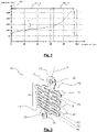
- Element 11 of the picture 1a can thus be made by cutting the outline in a metal plate and then making three vertical rows of holes 18 in staggered rows.
- the holes 18 of a given line are located between two holes 18 of an adjacent line.
- the holes 18 could for example take a diamond shape.
- Element 11 of the figure 1b can be made by cutting the outline in a metal plate and then making a vertical line of holes 18 having a rectangular shape.
- Element 11 of the picture 3 can be made by cutting the contour in a metal plate and then making two vertical rows of holes 18 staggered.
- the holes 18 of a given line are located between two holes 18 of the adjacent vertical row of holes 18.
- the holes 18 could for example take a diamond shape.
- the strands 16 of the energy absorption zone 14 can have various dimensions and/or orientations and/or types of material so as to adapt to an occupant's morphology.
- the mesh of the upper part of the element 11 comprises, in the unconstrained state, strands 16 having a horizontal orientation; while the mesh of the lower part comprises, in the unconstrained state, strands 16 having an orientation inclined with respect to a horizontal direction.
- a plurality of energy absorbing elements 11 are stacked on top of each other and configured to activate in cascade depending on an occupant's morphology.
- first anchoring points 12 of the superimposed elements 11 have holes 19 which coincide with each other and which are intended to cooperate with a fixed axis of the seat.
- second anchor point 13 of the first element 11 has a circular hole 20 to cooperate with an axis of the movable seat in the event of an impact causing the stretching of the element 11, as explained in more detail below.
- the following elements 11 comprise anchor points 13 constituted by oblong holes 21 having end edges offset longitudinally with respect to each other. The length of the oblong holes 21 increases as one moves away from the anchor point 13 of the first element 11.
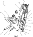
- the figure 7 shows a helicopter seat 22 comprising two support legs 23 provided with fasteners 24 for fixing to the rails of the aircraft.
- a seat structure 25 comprises a front edge 25.1 rotatably mounted relative to the support legs 23 and a rear edge 25.2 mounted suspended relative to the support legs 23 via at least one energy absorber 10.
- a first anchor point 12 of the energy absorber 10 cooperates with a pin 28 secured to a support foot 23 and a second anchor point 13 cooperates with a pin 29 secured to the rear edge 25.2 of the seat structure 25.
- the pin 29 integral with the rear edge 25.2 of the seat structure 25 is inserted inside a groove 30 formed in an upright 31 of the corresponding support foot 23.
- the groove 30 is able to guide a movement of the rear edge 25.2 of the seat structure 25 when a tensile force is applied between the anchor points 12, 13 during an impact.
- the seat structure 25 moves downwards following the stretching of the energy absorber 10 by rotating around the axis 28 integral with the support foot 23.
- the movement of the seat under the seat 22 is controlled thanks to the groove 30 which guides the axis 29 of the rear edge 25.2 connected to the anchor point 13 of the absorber 10, the first anchor point 12 fixed to the support foot 23 forming a frame being stationary.
- an energy absorber 10 is arranged on each side of the seat structure 25.
- a protective cover 35 of the energy absorber 10 is mounted on each upright 31 of the support legs 23.
- the seat 22 may also include a lumbar support 32 associated with an upper portion of the backrest 33 extending between the two support legs 23.
- a lumbar support 32 associated with an upper portion of the backrest 33 extending between the two support legs 23.
- the seat 22 comprises a connecting crosspiece between the two support legs 23 as well as a headrest.
Landscapes
- Engineering & Computer Science (AREA)
- General Engineering & Computer Science (AREA)
- Mechanical Engineering (AREA)
- Vibration Dampers (AREA)
- Aviation & Aerospace Engineering (AREA)
- Seats For Vehicles (AREA)
Claims (10)
- Energieabsorber (10) für einen Flugzeugsitz (22), insbesondere für einen Hubschraubersitz, mit mindestens einem Energieabsorptionselement (11), aufweisend:- einen ersten Verankerungspunkt (12) und einen zweiten Verankerungspunkt (13),- eine sich zwischen dem ersten Verankerungspunkt (12) und dem zweiten Verankerungspunkt (13) erstreckende Energieabsorptionszone (14), wobei die Energieabsorptionszone (14) beim Aufbringen einer Zugkraft zwischen dem ersten Verankerungspunkt (12) und dem zweiten Verankerungspunkt (13) dehnbar ist,- wobei die Energieabsorptionszone (14) eine Maschenstruktur mit mehreren mittels Verbindungsabschnitten (17) miteinander verbundenen Strängen (16) aufweist, und wobei mindestens ein Verbindungsabschnitt (17) eine Verbindung zwischen mindestens drei Strängen (16) der Energieabsorptionszone (14) bereitstellt,dadurch gekennzeichnet, dass das Energieabsorptionselement (11) eine asymmetrische Konfiguration bezüglich einer durch den ersten Verankerungspunkt (12) und den zweiten Verankerungspunkt (13) verlaufenden Zugachse (X) aufweist.
- Energieabsorber (10) nach Anspruch 1, dadurch gekennzeichnet, dass die Energieabsorptionszone (14) mindestens einen Teil umfasst, der in Längsrichtung eine Folge von Reihen (R1-Rn) von Verbindungsabschnitten (17) umfasst, wobei jede Reihe zwei Verbindungsabschnitte (17) umfasst.
- Energieabsorber (10) nach einem der Ansprüche 1 bis 2, dadurch gekennzeichnet, dass die Stränge (16) der Energieabsorptionszone (14) unterschiedliche Abmessungen und/oder Orientierungen und/oder Materialarten zum Anpassen an die Morphologie eines Insassen aufweisen.
- Energieabsorber (10) nach einem der Ansprüche 1 bis 3, dadurch gekennzeichnet, dass er mehrere übereinander gestapelte Energieabsorptionselemente (11) umfasst, die so konfiguriert sind, dass sie in Kaskade gemäß der Morphologie eines Insassen aktiviert werden.
- Energieabsorber (10) nach einem der Ansprüche 1 bis 4, dadurch gekennzeichnet, dass das Energieabsorptionselement (11) aus einem metallischen Material, insbesondere Edelstahl, hergestellt ist.
- Flugzeugsitz (22), insbesondere Hubschraubersitz, dadurch gekennzeichnet, dass er mindestens einen Energieabsorber (10) nach einem der vorhergehenden Ansprüche umfasst.
- Flugzeugsitz (22) nach Anspruch 6, dadurch gekennzeichnet, dass er umfasst:- zwei Stützbeine (23) mit Befestigungselementen (24) zur Befestigung an Schienen des Flugzeugs,- eine Sitzflächenstruktur (25) mit einer in Bezug auf die Stützbeine (23) drehbar gelagerten Vorderkante (25.1) und einer in Bezug auf die Stützbeine (23) über zumindest einen Energieabsorber (10) hängend gelagerten Hinterkante (25.2).
- Flugzeugsitz (22) nach Anspruch 7, dadurch gekennzeichnet, dass der Energieabsorber (10) einen ersten Verankerungspunkt (12), der mit einem mit einem Stützbein (23) einstückigen Zapfen (28) zusammenwirkt, und einen zweiten Verankerungspunkt (13), der mit einem mit der Hinterkante (25.2) der Sitzflächenstruktur (25) einstückigen Zapfen (29) zusammenwirkt, umfasst.
- Flugzeugsitz (22) nach Anspruch 8, dadurch gekennzeichnet, dass der Zapfen (29), der einstückig mit der Hinterkante (25.2) der Sitzflächenstruktur (25) ist, in eine Nut (30) in einem Pfosten (31) des entsprechenden Stützbeins (23) eingesetzt ist, wobei die Nut (30) eine Bewegung der Hinterkante (25.2) der Sitzflächenstruktur (25) führen kann, wenn eine Zugkraft zwischen dem ersten Verankerungspunkt (12) und dem zweiten Verankerungspunkt (13) aufgebracht wird.
- Flugzeugsitz (22) nach einem der Ansprüche 6 bis 9, dadurch gekennzeichnet, dass er eine Schutzabdeckung (35) für den Energieabsorber (10) umfasst.
Applications Claiming Priority (2)
| Application Number | Priority Date | Filing Date | Title |
|---|---|---|---|
| FR1771148A FR3073028B1 (fr) | 2017-10-31 | 2017-10-31 | Absorbeur d'energie pour siege d'aeronef |
| PCT/EP2018/078605 WO2019086264A1 (fr) | 2017-10-31 | 2018-10-18 | Absorbeur d'énergie pour siège d'aéronef |
Publications (2)
| Publication Number | Publication Date |
|---|---|
| EP3704396A1 EP3704396A1 (de) | 2020-09-09 |
| EP3704396B1 true EP3704396B1 (de) | 2022-12-07 |
Family
ID=60515731
Family Applications (1)
| Application Number | Title | Priority Date | Filing Date |
|---|---|---|---|
| EP18789140.3A Active EP3704396B1 (de) | 2017-10-31 | 2018-10-18 | Energieabsorber für einen luftfahrzeugsitz |
Country Status (5)
| Country | Link |
|---|---|
| US (1) | US12031603B2 (de) |
| EP (1) | EP3704396B1 (de) |
| CN (1) | CN111295531B (de) |
| FR (1) | FR3073028B1 (de) |
| WO (1) | WO2019086264A1 (de) |
Families Citing this family (3)
| Publication number | Priority date | Publication date | Assignee | Title |
|---|---|---|---|---|
| FR3073028B1 (fr) * | 2017-10-31 | 2020-02-21 | Zodiac Seats France | Absorbeur d'energie pour siege d'aeronef |
| FI12778Y1 (fi) * | 2019-11-25 | 2020-09-30 | Labrys Oy | Jousielementti |
| US12195187B2 (en) | 2022-10-14 | 2025-01-14 | Ami Industries, Inc. | Offset helicopter pilot seat with singular energy absorber |
Family Cites Families (15)
| Publication number | Priority date | Publication date | Assignee | Title |
|---|---|---|---|---|
| US3482872A (en) * | 1968-02-12 | 1969-12-09 | Thomas E Chamberlain | Seat belt assembly |
| JPS492728B1 (de) * | 1968-12-17 | 1974-01-22 | ||
| DE2452336C2 (de) * | 1974-11-05 | 1984-06-14 | Porsche Design, 7000 Stuttgart | Energieabsorbierendes Glied, vorzugsweise als Kraftbegrenzer für Sicherheitsgurte |
| US4753772A (en) * | 1986-02-21 | 1988-06-28 | Westinghouse Electric Corp. | Multi-strap shock absorber |
| FR2695177B1 (fr) * | 1992-08-25 | 1994-11-10 | Neyrpic Framatome Mecanique | Dispositif d'absorption d'énergie à forte capacité d'allongement et utilisation de ce dispositif dans les structures à câbles pour retenir des éboulements. |
| GB9225001D0 (en) * | 1992-11-30 | 1993-01-20 | Aircraft Furnishing Ltd | Energy absorber |
| US5961146A (en) * | 1996-01-18 | 1999-10-05 | Nsk Ltd. | Shock absorbing type steering column assembly |
| US20050012319A1 (en) * | 2003-07-14 | 2005-01-20 | Kurt Schulz | Load limiting structure for vehicle occupant restraint system |
| DE102006023688B4 (de) * | 2006-05-19 | 2015-12-17 | Scherdel Innotec Forschungs- Und Entwicklungs-Gmbh | Personen-Schutzvorrichtung und Kraftfahrzeug damit |
| US20090173856A1 (en) * | 2008-01-08 | 2009-07-09 | Smart Technologies Inc. | Safety Device For A Cantilevered Beam And Boom Assembly Incorporating The Same |
| FR2930520B1 (fr) * | 2008-04-28 | 2010-08-20 | Eurocopter France | Siege anti-ecrasement d'un vehicule |
| FR2930613B1 (fr) | 2008-04-28 | 2012-04-20 | Eurocopter France | Element absorbant d'energie |
| SE0900992A1 (sv) * | 2009-07-16 | 2011-01-17 | Modul System Hh Ab | Fästanordning och användning av fästanordning |
| MX2012004781A (es) * | 2009-10-23 | 2012-06-12 | Db Ind Inc | Absorvente de energia. |
| FR3073028B1 (fr) * | 2017-10-31 | 2020-02-21 | Zodiac Seats France | Absorbeur d'energie pour siege d'aeronef |
-
2017
- 2017-10-31 FR FR1771148A patent/FR3073028B1/fr not_active Expired - Fee Related
-
2018
- 2018-10-18 CN CN201880070584.6A patent/CN111295531B/zh active Active
- 2018-10-18 WO PCT/EP2018/078605 patent/WO2019086264A1/fr not_active Ceased
- 2018-10-18 US US16/760,837 patent/US12031603B2/en active Active
- 2018-10-18 EP EP18789140.3A patent/EP3704396B1/de active Active
Also Published As
| Publication number | Publication date |
|---|---|
| EP3704396A1 (de) | 2020-09-09 |
| FR3073028A1 (fr) | 2019-05-03 |
| CN111295531A (zh) | 2020-06-16 |
| FR3073028B1 (fr) | 2020-02-21 |
| US12031603B2 (en) | 2024-07-09 |
| CN111295531B (zh) | 2022-09-30 |
| WO2019086264A1 (fr) | 2019-05-09 |
| US20200262563A1 (en) | 2020-08-20 |
Similar Documents
| Publication | Publication Date | Title |
|---|---|---|
| EP0659642B1 (de) | Flugzeugsitz insbesondere für einen Drehflügler mit abhängig vom Gewicht des Fluggastes selbsttätig regelbarer energieabsorbierender Vorrichtung | |
| EP2113457B1 (de) | Fahrzeug Unfallsitz | |
| EP1719701B1 (de) | Sicherheitsflugsitz | |
| EP0286471B1 (de) | Stützstruktur mit Stossdämpfer und dynamischer Festigkeit für einen Luftfahrzeugsitz und Sitz mit dieser Struktur | |
| EP2978633B1 (de) | Fahrzeugsitz ausgestattet mit einem klappbaren element, wie z.b. einem klapptisch | |
| EP3704396B1 (de) | Energieabsorber für einen luftfahrzeugsitz | |
| EP2763870B1 (de) | Kraftfahrzeugsitz für ein kind mit einstellbarer höhe des sitzelements | |
| FR2996501A1 (fr) | Siege auto pour enfant, a assise reglable en hauteur | |
| FR2936218A1 (fr) | Structure primaire pour aeronef en materiau composite a tenue au crash amelioree et element structural absorbeur d'energie associe. | |
| EP4219308B1 (de) | Flugzeugsitz zur dämpfung eines vertikalen aufpralls | |
| EP3354571B1 (de) | Luftfahrzeugsitz, der mit einer in die sitzwanne integrierten energieabsorptionszone ausgestattet ist | |
| EP3003831B1 (de) | Rohkarosseriestruktursystem eines kraftfahrzeugs mit einer seitenaufprallstütze | |
| EP4347399B1 (de) | Sitzschale, insbesondere für einen flugzeugsitz, mit einem rohr zur absorption kinetischer energie | |
| EP3283375B1 (de) | Flugzeugsitz mit verstärktem sitzuntergestell | |
| EP4347400B1 (de) | Sitzschale, insbesondere für einen flugzeugsitz, mit einem beckenabstandsbereich | |
| FR2776589A1 (fr) | Dispositif d'evacuation de masse, structure de siege, siege et vehicule equipe de ce dispositif | |
| EP3024693B1 (de) | Fahrzeugsitz | |
| FR2495101A1 (fr) | Siege de securite anticrash notamment pour aeronef | |
| FR2987322A1 (fr) | Assise de siege de vehicule comportant une traverse d'anti sous-marinage. | |
| FR2972974A1 (fr) | Banquette allegee et resistante pour vehicule automobile | |
| FR2946586A1 (fr) | Dossier de siege pour vehicule. | |
| FR3151548A1 (fr) | Element de dossier de banquette arriere de vehicule | |
| FR2969551A1 (fr) | Siege de vehicule. | |
| FR3021919A1 (fr) | Armature d'assise de siege de vehicule automobile comportant un dispositif d'anti-sous-marinage |
Legal Events
| Date | Code | Title | Description |
|---|---|---|---|
| STAA | Information on the status of an ep patent application or granted ep patent |
Free format text: STATUS: UNKNOWN |
|
| STAA | Information on the status of an ep patent application or granted ep patent |
Free format text: STATUS: THE INTERNATIONAL PUBLICATION HAS BEEN MADE |
|
| PUAI | Public reference made under article 153(3) epc to a published international application that has entered the european phase |
Free format text: ORIGINAL CODE: 0009012 |
|
| STAA | Information on the status of an ep patent application or granted ep patent |
Free format text: STATUS: REQUEST FOR EXAMINATION WAS MADE |
|
| 17P | Request for examination filed |
Effective date: 20200407 |
|
| AK | Designated contracting states |
Kind code of ref document: A1 Designated state(s): AL AT BE BG CH CY CZ DE DK EE ES FI FR GB GR HR HU IE IS IT LI LT LU LV MC MK MT NL NO PL PT RO RS SE SI SK SM TR |
|
| AX | Request for extension of the european patent |
Extension state: BA ME |
|
| DAV | Request for validation of the european patent (deleted) | ||
| DAX | Request for extension of the european patent (deleted) | ||
| GRAP | Despatch of communication of intention to grant a patent |
Free format text: ORIGINAL CODE: EPIDOSNIGR1 |
|
| STAA | Information on the status of an ep patent application or granted ep patent |
Free format text: STATUS: GRANT OF PATENT IS INTENDED |
|
| INTG | Intention to grant announced |
Effective date: 20220922 |
|
| GRAS | Grant fee paid |
Free format text: ORIGINAL CODE: EPIDOSNIGR3 |
|
| GRAA | (expected) grant |
Free format text: ORIGINAL CODE: 0009210 |
|
| STAA | Information on the status of an ep patent application or granted ep patent |
Free format text: STATUS: THE PATENT HAS BEEN GRANTED |
|
| AK | Designated contracting states |
Kind code of ref document: B1 Designated state(s): AL AT BE BG CH CY CZ DE DK EE ES FI FR GB GR HR HU IE IS IT LI LT LU LV MC MK MT NL NO PL PT RO RS SE SI SK SM TR |
|
| REG | Reference to a national code |
Ref country code: GB Ref legal event code: FG4D Free format text: NOT ENGLISH |
|
| REG | Reference to a national code |
Ref country code: CH Ref legal event code: EP Ref country code: AT Ref legal event code: REF Ref document number: 1536483 Country of ref document: AT Kind code of ref document: T Effective date: 20221215 |
|
| REG | Reference to a national code |
Ref country code: DE Ref legal event code: R096 Ref document number: 602018044020 Country of ref document: DE |
|
| REG | Reference to a national code |
Ref country code: IE Ref legal event code: FG4D Free format text: LANGUAGE OF EP DOCUMENT: FRENCH |
|
| REG | Reference to a national code |
Ref country code: LT Ref legal event code: MG9D |
|
| REG | Reference to a national code |
Ref country code: NL Ref legal event code: MP Effective date: 20221207 |
|
| PG25 | Lapsed in a contracting state [announced via postgrant information from national office to epo] |
Ref country code: SE Free format text: LAPSE BECAUSE OF FAILURE TO SUBMIT A TRANSLATION OF THE DESCRIPTION OR TO PAY THE FEE WITHIN THE PRESCRIBED TIME-LIMIT Effective date: 20221207 Ref country code: NO Free format text: LAPSE BECAUSE OF FAILURE TO SUBMIT A TRANSLATION OF THE DESCRIPTION OR TO PAY THE FEE WITHIN THE PRESCRIBED TIME-LIMIT Effective date: 20230307 Ref country code: LT Free format text: LAPSE BECAUSE OF FAILURE TO SUBMIT A TRANSLATION OF THE DESCRIPTION OR TO PAY THE FEE WITHIN THE PRESCRIBED TIME-LIMIT Effective date: 20221207 Ref country code: FI Free format text: LAPSE BECAUSE OF FAILURE TO SUBMIT A TRANSLATION OF THE DESCRIPTION OR TO PAY THE FEE WITHIN THE PRESCRIBED TIME-LIMIT Effective date: 20221207 Ref country code: ES Free format text: LAPSE BECAUSE OF FAILURE TO SUBMIT A TRANSLATION OF THE DESCRIPTION OR TO PAY THE FEE WITHIN THE PRESCRIBED TIME-LIMIT Effective date: 20221207 |
|
| REG | Reference to a national code |
Ref country code: AT Ref legal event code: MK05 Ref document number: 1536483 Country of ref document: AT Kind code of ref document: T Effective date: 20221207 |
|
| PG25 | Lapsed in a contracting state [announced via postgrant information from national office to epo] |
Ref country code: RS Free format text: LAPSE BECAUSE OF FAILURE TO SUBMIT A TRANSLATION OF THE DESCRIPTION OR TO PAY THE FEE WITHIN THE PRESCRIBED TIME-LIMIT Effective date: 20221207 Ref country code: PL Free format text: LAPSE BECAUSE OF FAILURE TO SUBMIT A TRANSLATION OF THE DESCRIPTION OR TO PAY THE FEE WITHIN THE PRESCRIBED TIME-LIMIT Effective date: 20221207 Ref country code: LV Free format text: LAPSE BECAUSE OF FAILURE TO SUBMIT A TRANSLATION OF THE DESCRIPTION OR TO PAY THE FEE WITHIN THE PRESCRIBED TIME-LIMIT Effective date: 20221207 Ref country code: HR Free format text: LAPSE BECAUSE OF FAILURE TO SUBMIT A TRANSLATION OF THE DESCRIPTION OR TO PAY THE FEE WITHIN THE PRESCRIBED TIME-LIMIT Effective date: 20221207 Ref country code: GR Free format text: LAPSE BECAUSE OF FAILURE TO SUBMIT A TRANSLATION OF THE DESCRIPTION OR TO PAY THE FEE WITHIN THE PRESCRIBED TIME-LIMIT Effective date: 20230308 |
|
| PG25 | Lapsed in a contracting state [announced via postgrant information from national office to epo] |
Ref country code: NL Free format text: LAPSE BECAUSE OF FAILURE TO SUBMIT A TRANSLATION OF THE DESCRIPTION OR TO PAY THE FEE WITHIN THE PRESCRIBED TIME-LIMIT Effective date: 20221207 |
|
| PG25 | Lapsed in a contracting state [announced via postgrant information from national office to epo] |
Ref country code: SM Free format text: LAPSE BECAUSE OF FAILURE TO SUBMIT A TRANSLATION OF THE DESCRIPTION OR TO PAY THE FEE WITHIN THE PRESCRIBED TIME-LIMIT Effective date: 20221207 Ref country code: RO Free format text: LAPSE BECAUSE OF FAILURE TO SUBMIT A TRANSLATION OF THE DESCRIPTION OR TO PAY THE FEE WITHIN THE PRESCRIBED TIME-LIMIT Effective date: 20221207 Ref country code: PT Free format text: LAPSE BECAUSE OF FAILURE TO SUBMIT A TRANSLATION OF THE DESCRIPTION OR TO PAY THE FEE WITHIN THE PRESCRIBED TIME-LIMIT Effective date: 20230410 Ref country code: EE Free format text: LAPSE BECAUSE OF FAILURE TO SUBMIT A TRANSLATION OF THE DESCRIPTION OR TO PAY THE FEE WITHIN THE PRESCRIBED TIME-LIMIT Effective date: 20221207 Ref country code: CZ Free format text: LAPSE BECAUSE OF FAILURE TO SUBMIT A TRANSLATION OF THE DESCRIPTION OR TO PAY THE FEE WITHIN THE PRESCRIBED TIME-LIMIT Effective date: 20221207 Ref country code: AT Free format text: LAPSE BECAUSE OF FAILURE TO SUBMIT A TRANSLATION OF THE DESCRIPTION OR TO PAY THE FEE WITHIN THE PRESCRIBED TIME-LIMIT Effective date: 20221207 |
|
| PG25 | Lapsed in a contracting state [announced via postgrant information from national office to epo] |
Ref country code: SK Free format text: LAPSE BECAUSE OF FAILURE TO SUBMIT A TRANSLATION OF THE DESCRIPTION OR TO PAY THE FEE WITHIN THE PRESCRIBED TIME-LIMIT Effective date: 20221207 Ref country code: IS Free format text: LAPSE BECAUSE OF FAILURE TO SUBMIT A TRANSLATION OF THE DESCRIPTION OR TO PAY THE FEE WITHIN THE PRESCRIBED TIME-LIMIT Effective date: 20230407 Ref country code: AL Free format text: LAPSE BECAUSE OF FAILURE TO SUBMIT A TRANSLATION OF THE DESCRIPTION OR TO PAY THE FEE WITHIN THE PRESCRIBED TIME-LIMIT Effective date: 20221207 |
|
| REG | Reference to a national code |
Ref country code: DE Ref legal event code: R097 Ref document number: 602018044020 Country of ref document: DE |
|
| PLBE | No opposition filed within time limit |
Free format text: ORIGINAL CODE: 0009261 |
|
| STAA | Information on the status of an ep patent application or granted ep patent |
Free format text: STATUS: NO OPPOSITION FILED WITHIN TIME LIMIT |
|
| PG25 | Lapsed in a contracting state [announced via postgrant information from national office to epo] |
Ref country code: DK Free format text: LAPSE BECAUSE OF FAILURE TO SUBMIT A TRANSLATION OF THE DESCRIPTION OR TO PAY THE FEE WITHIN THE PRESCRIBED TIME-LIMIT Effective date: 20221207 |
|
| 26N | No opposition filed |
Effective date: 20230908 |
|
| PG25 | Lapsed in a contracting state [announced via postgrant information from national office to epo] |
Ref country code: SI Free format text: LAPSE BECAUSE OF FAILURE TO SUBMIT A TRANSLATION OF THE DESCRIPTION OR TO PAY THE FEE WITHIN THE PRESCRIBED TIME-LIMIT Effective date: 20221207 |
|
| PG25 | Lapsed in a contracting state [announced via postgrant information from national office to epo] |
Ref country code: IT Free format text: LAPSE BECAUSE OF FAILURE TO SUBMIT A TRANSLATION OF THE DESCRIPTION OR TO PAY THE FEE WITHIN THE PRESCRIBED TIME-LIMIT Effective date: 20221207 Ref country code: MC Free format text: LAPSE BECAUSE OF FAILURE TO SUBMIT A TRANSLATION OF THE DESCRIPTION OR TO PAY THE FEE WITHIN THE PRESCRIBED TIME-LIMIT Effective date: 20221207 |
|
| REG | Reference to a national code |
Ref country code: CH Ref legal event code: PL |
|
| REG | Reference to a national code |
Ref country code: BE Ref legal event code: MM Effective date: 20231031 |
|
| PG25 | Lapsed in a contracting state [announced via postgrant information from national office to epo] |
Ref country code: LU Free format text: LAPSE BECAUSE OF NON-PAYMENT OF DUE FEES Effective date: 20231018 |
|
| PG25 | Lapsed in a contracting state [announced via postgrant information from national office to epo] |
Ref country code: LU Free format text: LAPSE BECAUSE OF NON-PAYMENT OF DUE FEES Effective date: 20231018 |
|
| PG25 | Lapsed in a contracting state [announced via postgrant information from national office to epo] |
Ref country code: CH Free format text: LAPSE BECAUSE OF NON-PAYMENT OF DUE FEES Effective date: 20231031 |
|
| PG25 | Lapsed in a contracting state [announced via postgrant information from national office to epo] |
Ref country code: CH Free format text: LAPSE BECAUSE OF NON-PAYMENT OF DUE FEES Effective date: 20231031 |
|
| PG25 | Lapsed in a contracting state [announced via postgrant information from national office to epo] |
Ref country code: BE Free format text: LAPSE BECAUSE OF NON-PAYMENT OF DUE FEES Effective date: 20231031 |
|
| PG25 | Lapsed in a contracting state [announced via postgrant information from national office to epo] |
Ref country code: IE Free format text: LAPSE BECAUSE OF NON-PAYMENT OF DUE FEES Effective date: 20231018 |
|
| PGFP | Annual fee paid to national office [announced via postgrant information from national office to epo] |
Ref country code: GB Payment date: 20240919 Year of fee payment: 7 |
|
| PG25 | Lapsed in a contracting state [announced via postgrant information from national office to epo] |
Ref country code: IE Free format text: LAPSE BECAUSE OF NON-PAYMENT OF DUE FEES Effective date: 20231018 |
|
| PG25 | Lapsed in a contracting state [announced via postgrant information from national office to epo] |
Ref country code: BG Free format text: LAPSE BECAUSE OF FAILURE TO SUBMIT A TRANSLATION OF THE DESCRIPTION OR TO PAY THE FEE WITHIN THE PRESCRIBED TIME-LIMIT Effective date: 20221207 |
|
| PG25 | Lapsed in a contracting state [announced via postgrant information from national office to epo] |
Ref country code: BG Free format text: LAPSE BECAUSE OF FAILURE TO SUBMIT A TRANSLATION OF THE DESCRIPTION OR TO PAY THE FEE WITHIN THE PRESCRIBED TIME-LIMIT Effective date: 20221207 |
|
| PG25 | Lapsed in a contracting state [announced via postgrant information from national office to epo] |
Ref country code: CY Free format text: LAPSE BECAUSE OF FAILURE TO SUBMIT A TRANSLATION OF THE DESCRIPTION OR TO PAY THE FEE WITHIN THE PRESCRIBED TIME-LIMIT; INVALID AB INITIO Effective date: 20181018 |
|
| PG25 | Lapsed in a contracting state [announced via postgrant information from national office to epo] |
Ref country code: HU Free format text: LAPSE BECAUSE OF FAILURE TO SUBMIT A TRANSLATION OF THE DESCRIPTION OR TO PAY THE FEE WITHIN THE PRESCRIBED TIME-LIMIT; INVALID AB INITIO Effective date: 20181018 |
|
| PG25 | Lapsed in a contracting state [announced via postgrant information from national office to epo] |
Ref country code: TR Free format text: LAPSE BECAUSE OF FAILURE TO SUBMIT A TRANSLATION OF THE DESCRIPTION OR TO PAY THE FEE WITHIN THE PRESCRIBED TIME-LIMIT Effective date: 20221207 |
|
| PGFP | Annual fee paid to national office [announced via postgrant information from national office to epo] |
Ref country code: DE Payment date: 20251020 Year of fee payment: 8 |
|
| PGFP | Annual fee paid to national office [announced via postgrant information from national office to epo] |
Ref country code: FR Payment date: 20251024 Year of fee payment: 8 |