EP3704354B1 - Verfahren zur steuerung einer spaltminimierung einer gasturbine - Google Patents
Verfahren zur steuerung einer spaltminimierung einer gasturbine Download PDFInfo
- Publication number
- EP3704354B1 EP3704354B1 EP19714116.1A EP19714116A EP3704354B1 EP 3704354 B1 EP3704354 B1 EP 3704354B1 EP 19714116 A EP19714116 A EP 19714116A EP 3704354 B1 EP3704354 B1 EP 3704354B1
- Authority
- EP
- European Patent Office
- Prior art keywords
- gap
- gas turbine
- operating parameter
- value
- actual value
- Prior art date
- Legal status (The legal status is an assumption and is not a legal conclusion. Google has not performed a legal analysis and makes no representation as to the accuracy of the status listed.)
- Active
Links
Images
Classifications
-
- F—MECHANICAL ENGINEERING; LIGHTING; HEATING; WEAPONS; BLASTING
- F01—MACHINES OR ENGINES IN GENERAL; ENGINE PLANTS IN GENERAL; STEAM ENGINES
- F01D—NON-POSITIVE DISPLACEMENT MACHINES OR ENGINES, e.g. STEAM TURBINES
- F01D11/00—Preventing or minimising internal leakage of working-fluid, e.g. between stages
- F01D11/08—Preventing or minimising internal leakage of working-fluid, e.g. between stages for sealing space between rotor blade tips and stator
- F01D11/14—Adjusting or regulating tip-clearance, i.e. distance between rotor-blade tips and stator casing
- F01D11/20—Actively adjusting tip-clearance
-
- F—MECHANICAL ENGINEERING; LIGHTING; HEATING; WEAPONS; BLASTING
- F01—MACHINES OR ENGINES IN GENERAL; ENGINE PLANTS IN GENERAL; STEAM ENGINES
- F01D—NON-POSITIVE DISPLACEMENT MACHINES OR ENGINES, e.g. STEAM TURBINES
- F01D11/00—Preventing or minimising internal leakage of working-fluid, e.g. between stages
- F01D11/08—Preventing or minimising internal leakage of working-fluid, e.g. between stages for sealing space between rotor blade tips and stator
- F01D11/14—Adjusting or regulating tip-clearance, i.e. distance between rotor-blade tips and stator casing
-
- F—MECHANICAL ENGINEERING; LIGHTING; HEATING; WEAPONS; BLASTING
- F01—MACHINES OR ENGINES IN GENERAL; ENGINE PLANTS IN GENERAL; STEAM ENGINES
- F01D—NON-POSITIVE DISPLACEMENT MACHINES OR ENGINES, e.g. STEAM TURBINES
- F01D25/00—Component parts, details, or accessories, not provided for in, or of interest apart from, other groups
- F01D25/08—Cooling; Heating; Heat-insulation
- F01D25/14—Casings modified therefor
-
- F—MECHANICAL ENGINEERING; LIGHTING; HEATING; WEAPONS; BLASTING
- F01—MACHINES OR ENGINES IN GENERAL; ENGINE PLANTS IN GENERAL; STEAM ENGINES
- F01D—NON-POSITIVE DISPLACEMENT MACHINES OR ENGINES, e.g. STEAM TURBINES
- F01D17/00—Regulating or controlling by varying flow
- F01D17/02—Arrangement of sensing elements
- F01D17/04—Arrangement of sensing elements responsive to load
-
- F—MECHANICAL ENGINEERING; LIGHTING; HEATING; WEAPONS; BLASTING
- F05—INDEXING SCHEMES RELATING TO ENGINES OR PUMPS IN VARIOUS SUBCLASSES OF CLASSES F01-F04
- F05D—INDEXING SCHEME FOR ASPECTS RELATING TO NON-POSITIVE-DISPLACEMENT MACHINES OR ENGINES, GAS-TURBINES OR JET-PROPULSION PLANTS
- F05D2270/00—Control
- F05D2270/30—Control parameters, e.g. input parameters
- F05D2270/305—Tolerances
-
- F—MECHANICAL ENGINEERING; LIGHTING; HEATING; WEAPONS; BLASTING
- F05—INDEXING SCHEMES RELATING TO ENGINES OR PUMPS IN VARIOUS SUBCLASSES OF CLASSES F01-F04
- F05D—INDEXING SCHEME FOR ASPECTS RELATING TO NON-POSITIVE-DISPLACEMENT MACHINES OR ENGINES, GAS-TURBINES OR JET-PROPULSION PLANTS
- F05D2270/00—Control
- F05D2270/30—Control parameters, e.g. input parameters
- F05D2270/335—Output power or torque
-
- F—MECHANICAL ENGINEERING; LIGHTING; HEATING; WEAPONS; BLASTING
- F05—INDEXING SCHEMES RELATING TO ENGINES OR PUMPS IN VARIOUS SUBCLASSES OF CLASSES F01-F04
- F05D—INDEXING SCHEME FOR ASPECTS RELATING TO NON-POSITIVE-DISPLACEMENT MACHINES OR ENGINES, GAS-TURBINES OR JET-PROPULSION PLANTS
- F05D2270/00—Control
- F05D2270/80—Devices generating input signals, e.g. transducers, sensors, cameras or strain gauges
Definitions
- the invention relates to a method for controlling a gap minimization of an adjustable gap between a rotor and a housing of a gas turbine, the gas turbine comprising a gap adjustment device, in particular a hydraulic one.
- the invention further relates to a control device for carrying out the method and a gas turbine with such a control device.
- Steps of the method include measuring at least one engine parameter; determining the engine power demand from the at least one engine parameter; and calculating the rotor gap given the determined motor power requirement.
- the rotor gap control device is controlled to increase or decrease the rotor tip clearance based on the difference between the calculated clearance and a predefined target clearance.
- EP 2 549 065 A1 also describes a system for operating a turbine including a rotating component and a non-rotating component separated from the rotating component by a gap.
- a first Actuator is connected to the non-rotating component and the first actuator comprises a shape memory alloy.
- a method of operating the turbine includes sensing a parameter that reflects the gap between the non-rotating component and the rotating component and generating a parameter signal that reflects the gap. The method further includes generating a control signal for at least one actuator based on the parameter signal and moving at least a portion of the non-rotating component relative to the rotating component to vary the gap.
- Another method for part-load operation of a gas turbine with an active hydraulic gap setting is, for example, from WO 2015/128193 A1 known.
- the invention is based on the object of proposing an improved HCO logic which, in particular, during a load change allows optimal use of the gap setting during operation of the gas turbine.
- a control device for carrying out the method comprising a gap adjustment device, in particular a hydraulic one, and means for determining the actual value of the operating parameter.
- the means for determining the actual value of the operating parameter can be sensors for direct measurement, or alternatively, another variable correlated with the operating parameter can be measured directly and the operating parameter can be calculated indirectly on this basis.
- the object is finally achieved according to the invention by a gas turbine with such a control device.
- Gap minimization is understood here to mean an axial offset of the rotor of the gas turbine against the direction of flow, which offset is carried out with the aid in particular of the hydraulic means for adjusting the gap between the rotor and the housing.
- HCO is equated with the term gap minimization.
- the gap minimization or the HCO function can be activated (the rotor is shifted towards the housing) or deactivated.
- the invention is based on the consideration of providing a new HCO logic that is above all simple and robust, but can minimize the dangers in the operating phases with gap optimization switched on. For this purpose, numerous investigations of transient maneuvers were carried out using computer simulations, which form the basis for the improved HCO logic.
- An operating parameter is used for the optimized gap setting, with the help of which the operating state of the gas turbine is recorded.
- the power of the gas turbine, a normalized relative power, temperatures or pressures along the main gas duct or also temperature and pressure conditions can be used as operating parameters.
- the operating parameter is chosen so that it reacts to a change in load.
- the computer simulation using the simulation program is carried out in particular outside of operation, e.g. in the development stage of the gas turbine.
- a simulation program is understood here to mean a so-called digital twin of the gas turbine.
- the simulation program or simulation model enables a more precise overview of the status of the turbine with a wide variety of parameter settings. Operating parameters that are better tailored to the application scenario can thus be determined in order to operate the gas turbine optimally. In this specific case, the behavior of the gas turbine in relation to the gap between the rotor and the housing is examined with ongoing changes in the operating parameter.
- the simulation data record generated by the simulation program is then used to select the upper threshold value and the lower threshold value in such a way that optimal use of the HCO is possible, in which the HCO is activated for as long as possible with acceptable losses in the gap.
- the essential feature for the evaluation of the simulations is that the narrowest gap of the different maneuvers should be as equal as possible to ensure that no maneuver "destroys" the column.
- the actual value of the operating parameter is continuously recorded, "continuous" including both the case of a continuous, uninterrupted, direct measurement or calculation from measurement data and the case of a direct measurement or calculation from measurement data at short time intervals.
- the currently recorded actual value is compared with the lower and the upper threshold value, with the progression of the actual value being divided into at least three operating regimes or ranges: a lower range, a middle transitional range and an upper range.
- the maximum value of the actual value is recorded over a period of time in the immediate past. Based on the maximum value, a limit value is determined with the help of the correlation from the simulation results, which is used when the actual value is in the transition range between the lower and the upper threshold value.
- the gas turbine In the low load range, the gas turbine is usually only operated for a very short time, if at all, due to the pollutant emissions and the low efficiency. Consequently the efficiency in this load range contributes only very negligibly to the overall efficiency over the operating cycle of the machine. In this respect, there is no need to activate the HCO in this difficult environment. For this reason, the lower threshold for the operating parameter is defined. In the lower range, below the lower threshold, gap minimization is therefore deactivated or remains deactivated if it was not already switched on or has already been switched off.
- the analyzes carried out show that in the high-load range of the gas turbine, in which range the HCO is usually switched on, it is not necessary to track or adjust the HCO, even in the event of load fluctuations. Even starting from a low-load range is uncritical for the use of gap minimization.
- the upper threshold value for the operating parameter is defined. Therefore, in the upper range, above the upper threshold, gap minimization is activated or remains activated if it was already activated.
- the correlation between the actual value of the operating parameter and the maximum value of the operating parameter from the immediate past is taken into account.
- the HCO function is activated or deactivated depending on the behavior of the gas turbine in the predefined period of time.
- the limit value of the operating parameter which depends on the maximum value, is required for this. If the actual value is above the limit value, ie between the limit value and the upper threshold value, gap minimization is or remains activated. However, if the actual value is below the limit value, ie between the lower threshold value and the limit value, gap optimization is or remains deactivated.
- the proposed method results in a very precise activation of the HCO function, as a result of which several HCO activation hours are gained during operation of the gas turbine, which has a positive effect on the efficiency of the gas turbine.
- the method limits the complexity of dividing the operating regimes of the gas turbine to just three cases where the HCO logic must decide whether to turn the HCO on or off.
- the HCO logic described above also offers a better match with the machine behavior and is independent of an active gap measurement.
- the relative power which is normalized to the rated power of the gas turbine, is used as the operating parameter.
- Relative power is directly coupled to absolute power, which is readily available in the gas turbine controller and does not require additional hardware to be captured.
- the period of time is between 20 minutes and 3 hours, in particular between 30 minutes and 90 minutes.
- the period of time is determined by the reaction time of the turbine and is therefore dependent on the machine.
- the period of time is specified in particular in the control of the gas turbine.
- the lower threshold value is preferably between 30% and 45% at a relative power. This means that the gap minimization is switched on only when at least 30% of the nominal power of the gas turbine has been reached. Below this relative power, the HCO function is intended to be permanently inactive.
- the upper threshold value is preferably between 50% and 65% at a relative power. At the latest when 65% of the rated power of the gas turbine is reached, depending on the case, this can also be as early as 50% of the rated power of the gas turbine occur, the HCO is activated and remains permanently active above the upper threshold.
- gap minimization is preferably activated with a delay when the actual value exceeds the limit value.
- a time-delayed activation of the HCO prevents a considerable load difference from being avoided by rapid manoeuvres. For this reason, another HCO lock is defined, which blocks HCO activation for a period of a few minutes up to a maximum of 30 minutes.
- the correlation between the limit value and the maximum value is preferably predefined.
- the relationship between the maximum value and the limit value is specified in particular in the form of a table. This is perfectly adequate for the application and very reliable and controllable. It is therefore only necessary to know the maximum value of the operating parameter in order to determine the limit value quickly and without great computational effort.
- a correlation between the is preferably for each stage Limit value and the maximum value predefined. The respective correlations are recorded in the table.
- the correlation between the limit value and the maximum value is determined by calculation. This takes place in particular according to a formula stored in the controller.
- the method steps are advantageously carried out continuously from the determination of the actual value of the operating parameter during operation of the gas turbine as soon as the gas turbine is put into operation.
- FIG 1 a graphical representation of the three power ranges is shown, into which the power of a gas turbine, not shown in detail, is divided with a gap adjustment device according to the new HCO logic and which is characterized by different operating regimes.
- the gap adjustment device which is in particular hydraulically driven, is part of a control device, not shown in detail here, which communicates in terms of data technology with sensors, also not shown, which monitor the operation of the gas turbine.
- the relative power P REL is plotted on the x-axis, which is formed by the current power normalized by the nominal power of the gas turbine.
- the maximum value of the relative power P MAX of the gas turbine is plotted on the Y axis.
- the three areas U, M and 0 on the X-axis are separated from one another by a lower threshold value P U and an upper threshold value P O .
- the power range is marked with U between zero and the lower threshold value P U .
- the power range is marked with 0 above the upper threshold value P O .
- Between the lower threshold value P U and the upper threshold value P O is the middle transition range M, in which a limit value P G lies.
- the line F which extends over the transition area M, shows the dependency of the limit value P G on the maximum value P MAX .
- this dependency is stored in a table which the controller can access.
- the table is based on a simulation data set that was generated using a simulation program or digital twin for this type of turbine.
- the decision as to whether the HCO is activated or deactivated or remains active or inactive is based on the development of an actual value P I of the relative power P REL .
- the maximum value P MAX of the actual value P I (see FIG 2 ) detected.
- the period of time is also stored in the control and is machine-specific. The period of time can also be shorter than 1 hour (eg the measurements of the relative power P REL from the last 45 minutes are used) or longer (eg 90 minutes).
- the controller switches off gap minimization or, if gap minimization is already inactive, it remains switched off.
- the controller switches on gap minimization or, if gap minimization is already active, it remains switched on.
- gap minimization is switched on or off depending on whether the actual value P I of the relative power P REL is below the limit value P G in area M' or above the limit value P G in area M".
- the limit value P G As already explained, the maximum power P MAX in the last hour can be derived from the maximum value P MAX using the correlation (F) stored in the controller.
- the maximum value P MAX can also be defined on the Y-axis, whereby for the activation or deactivation of the gap minimization it is only taken into account which is the highest level, which is the maximum value P MAX in the was exceeded in the last hour. For example, between 3 and 10 such steps can be defined, which can also be of different sizes.
- the line F looks slightly different for each stage, ie the predefined or calculated correlation between the limit value P G and the maximum value P MAX can vary from stage to stage.
- a further blocking of the HCO can be installed, which blocks the HCO activation for eg 15 min.
- the blocking takes effect after a significant increase in load or power in the transition region M or in the upper region 0, which follows a significant drop in load or power in the lower region U.
Landscapes
- Engineering & Computer Science (AREA)
- Mechanical Engineering (AREA)
- General Engineering & Computer Science (AREA)
- Control Of Turbines (AREA)
- Turbine Rotor Nozzle Sealing (AREA)
Description
- Die Erfindung betrifft ein Verfahren zur Steuerung einer Spaltminimierung eines einstellbaren Spalts zwischen einem Rotor und einem Gehäuse einer Gasturbine, wobei die Gasturbine eine, insbesondere hydraulische, Spalteinstellvorrichtung umfasst. Die Erfindung betrifft weiterhin eine Steuervorrichtung zur Durchführung des Verfahrens sowie eine Gasturbine mit einer solchen Steuervorrichtung.
- Um einen maximalen Gasturbinenwirkungsgrad zu ermöglichen, ist es von entscheidender Bedeutung, die Spalte zwischen den rotierenden und den statischen Bauteilen während des Betriebs möglichst klein zu halten. Bei einem konischen Turbinen-Strömungskanal ist eine Möglichkeit hierzu, nachdem transiente Phasen, in welchen die Spalte an den Schaufelspitzen sich maximal verengen, durchfahren sind, den Rotor im stationären Hochlast-Betrieb z.B. mit einer Hydraulik axial zu verfahren. Wird der Rotor gegen die Strömungsrichtung verfahren, dann reduzieren sich die Spalte.
- Aus der
EP 2 843 198 A1 gehen ein Verfahren sowie eine Vorrichtung zum Steuern eines Rotorspalts (Tip Clearance) eines Gasturbinentriebwerks eines Flugzeugs hervor. Schritte des Verfahrens umfassen das Messen von mindestens einem Motorparameter; Bestimmen der Motorleistungsanforderung aus dem mindestens einen Motorparameter; und Berechnen des Rotorspaltes angesichts des bestimmten Motorleistungsbedarfs. Die Vorrichtung zum Steuern des Rotorspalts wird gesteuert, um den Rotorspitzenfreiraum, basierend auf der Differenz zwischen dem berechneten Freiraum und einem vordefinierten Zielfreiraum zu erhöhen oder zu verringern. - In der
EP 2 549 065 A1 ist ebenfalls ein System zum Betreiben einer Turbine umfassend eine rotierende Komponente und eine nicht rotierende Komponente, die von der rotierenden Komponente durch einen Spalt getrennt ist, beschrieben. Ein erster Aktuator ist mit der nicht rotierenden Komponente verbunden, und der erste Aktuator umfasst eine Formgedächtnislegierung. Ein Verfahren zum Betreiben der Turbine umfasst das Erfassen eines Parameters, der den Spalt zwischen der nicht rotierenden Komponente und der rotierenden Komponente widerspiegelt, und das Erzeugen eines Parametersignals, das den Spalt reflektiert. Das Verfahren umfasst ferner das Erzeugen eines Steuersignals für mindestens ein Stellglied auf der Grundlage des Parametersignals und das Bewegen mindestens eines Teils der nicht rotierenden Komponente relativ zu der rotierenden Komponente, um den Spalt zu verändern. - Aus der
WO 2014/016153 A1 ist ein Verfahren zur Minimierung eines einstellbaren Spalts zwischen einer Laufschaufel und einem Gehäuse einer Turbine bekannt. Durch Verschiebung von Läufer und Gehäuse gegeneinander, soll der Spalt zwischen Läufer und Gehäuse auf einfache Art und Weise minimiert werden. Dazu wird ein Ausgangssignal eines dem Läufer und/oder dem Gehäuse zugeordneten Körperschallüberwachungssystems als Maß für die Größe des Spalts und damit zur Einstellung eines minimalen Spalts herangezogen. - Ein weiteres Verfahren zum Teillast-Betrieb einer Gasturbine bei aktiver hydraulischer Spalteinstellung ist beispielsweise aus der
WO 2015/128193 A1 bekannt. - Um ein marktfähiges Produkt zu erzeugen, muss die Entscheidung über die angefahrene Position des Rotors automatisch gesteuert oder geregelt werden. Da eine dauerhafte Messung der Betriebsspalte technisch schwer umsetzbar bzw. sehr teuer ist, ist eine andere Vorgehensweise nötig. Hier wird in der Steuerung der Gasturbine eine HCO (Hydraulic Clearance Optimisation) Logik benötigt, die basierend auf messbaren Größen vorgibt, wie die Spaltoptimierung zu verfahren ist.
- Der Erfindung liegt die Aufgabe zugrunde, eine verbesserte HCO Logik vorzuschlagen, die insbesondere bei einem Lastwechsel während des Betriebs der Gasturbine eine optimale Nutzung der Spalteinstellung ermöglicht.
- Die Aufgabe wird erfindungsgemäß gelöst durch ein Verfahren zur Steuerung einer Spaltminimierung eines einstellbaren Spalts zwischen einem Rotor und einem Gehäuse einer Gasturbine, wobei die Gasturbine eine, insbesondere hydraulische, Spalteinstellvorrichtung umfasst, enthaltend folgende Schritte:
- mit Hilfe eines Simulationsprogramms wird der Betrieb der Gasturbine bei unterschiedlichen Parametereinstellungen abgebildet und ein Simulationsdatensatz wird erstellt, der die Abhängigkeit der Spaltgröße von einem Betriebsparameter enthält,
- anhand vom Simulationsdatensatz werden ein unterer Schwellwert und ein oberer Schwellwert für den Betriebsparameter festgelegt,
- weiterhin wird für einen Übergangsbereich zwischen dem unteren Schwellwert und dem oberen Schwellwert eine Korrelation zwischen dem Betriebsparameter und einem Maximalwert des Betriebsparameters aus dem Simulationsdatensatz extrahiert,
- während des Betriebs der Gasturbine wird laufend ein Istwert des Betriebsparameters ermittelt und mit dem unteren Schwellwert und dem oberen Schwellwert verglichen,
- und über eine vorgegebene Zeitspanne wird der Maximalwert des Istwertes bestimmt,
- unterhalb des unteren Schwellwerts liegt, die Spaltminimierung deaktiviert wird,
- oberhalb des oberen Schwellwerts liegt, die Spaltminimierung aktiviert wird,
- im Übergangsbereich liegt, mit Hilfe des Maximalwerts aus der vorgegebenen Zeitspanne unter Heranziehung der Korrelation ein Grenzwert für den Betriebsparameter ermittelt wird und die Spaltminimierung aktiviert wird, wenn der Istwert oberhalb des Grenzwertes liegt und deaktiviert wird, wenn der Istwert unterhalb des Grenzwerts liegt.
- Die Aufgabe wird weiterhin erfindungsgemäß gelöst durch eine Steuervorrichtung zur Durchführung des Verfahrens, umfassend eine, insbesondere hydraulische, Spalteinstellvorrichtung sowie Mittel zur Ermittlung des Istwerts des Betriebsparameters. In Abhängigkeit vom Betriebsparameter können die Mittel zur Ermittlung des Istwerts des Betriebsparameters hierbei Sensoren für eine direkte Messung sein oder alternativ kann eine andere, mit dem Betriebsparameter korrelierte Größe direkt gemessen und auf dieser Grundlage der Betriebsparameter rechnerisch indirekt ermittelt werden.
- Die Aufgabe wird schließlich erfindungsgemäß gelöst durch eine Gasturbine mit einer solchen Steuervorrichtung.
- Die in Bezug auf das Verfahren nachstehend angeführten Vorteile und bevorzugten Ausgestaltungen lassen sich sinngemäß auf die Steuervorrichtung und die Gasturbine übertragen.
- Unter Spaltminimierung wird hierbei ein axialer Versatz des Rotors der Gasturbine gegen die Strömungsrichtung verstanden, welcher Versatz mit Hilfe insbesondere der hydraulischen Mittel zum Einstellen des Spaltes zwischen dem Rotor und dem Gehäuse durchgeführt wird. Der Begriff HCO wird im weiteren Text mit dem Begriff Spaltminimierung gleichgesetzt. Die Spaltminimierung bzw. die HCO-Funktion kann dabei aktiviert (der Rotor ist zum Gehäuse hin verschoben) oder deaktiviert werden.
- Unter "aktiviert wird" bzw. "deaktiviert wird" soll nicht alleine das Ein- bzw. Ausschalten der HCO verstanden, sondern im Falle, dass die Spaltminimierung bereits aktiv ist, ist "aktiviert werden" gleichzusetzen mit "aktiviert bleiben". Das Gleiche bezieht sich auf eine bereits ausgeschaltete Spaltminimierung, in diesem Fall bedeutet "deaktiviert werden" auch "deaktiviert bleiben".
- Die Erfindung basiert auf der Überlegung, eine neue HCO Logik bereitzustellen, die vor allem einfach und robust ist, jedoch die Gefahren in den Betriebsphasen mit eingeschalteter Spaltoptimierung minimieren kann. Hierzu wurden zahlreiche Untersuchungen von transienten Manövern mittels Computersimulation durchgeführt, welche die Grundlage für die verbesserte HCO Logik bilden.
- Für die optimierte Spalteinstellung wird ein Betriebsparameter herangezogen, mit dessen Hilfe der Betriebszustand der Gasturbine erfasst wird. Als Betriebsparameter kann z.B. die Leistung der Gasturbine, eine normierte relative Leistung, Temperaturen oder Drücke entlang des Hauptgaskanals oder auch Temperatur- und Druckverhältnisse verwendet werden. Der Betriebsparameter ist dabei so gewählt, dass er auf eine Laständerung reagiert.
- Die Computersimulation mittels des Simulationsprogramms erfolgt insbesondere außerhalb des Betriebs, z.B. im Entwicklungsstadium der Gasturbine. Unter Simulationsprogramm wird hierbei ein sogenannter digitaler Zwilling der Gasturbine verstanden. Das Simulationsprogramm oder Simulationsmodell ermöglicht einen genaueren Überblick über den Status der Turbine bei unterschiedlichsten Parametereinstellungen. Somit lassen sich besser auf das Einsatzszenario abgestimmte Betriebsparameter ermitteln, um die Gasturbine optimal zu betreiben. Im konkreten Fall wird das Verhalten der Gasturbine in Bezug auf den Spalt zwischen dem Rotor und dem Gehäuse bei den laufenden Veränderungen des Betriebsparameters untersucht.
- Der durch das Simulationsprogramm generierte Simulationsdatensatz dient anschließend dazu, den oberen Schwellwert und den unteren Schwellwert derart zu wählen, dass eine optimale Nutzung der HCO möglich ist, bei der die HCO so lange wie möglich aktiviert ist unter akzeptablen Verlusten der Spalte. Das wesentliche Merkmal für die Auswertung der Simulationen ist dabei, dass der engste Spalt der unterschiedlichen Manöver möglichst gleich sein soll, um sicherzustellen, dass nicht ein Manöver die Spalte "zerstört".
- Eine Erkenntnis aus bisherigen Analysen ist, dass es insbesondere große Lastreduzierungen sind, die zu einer transienten Spaltverkleinerung führen und mit denen somit eine HCO Deaktivierung einhergehen muss. Es gilt somit den Maximalwert des Betriebsparameters aus der Zeit vor einem Lastsprung zu berücksichtigen, denn der Maximalwert des Betriebsparameters verschiebt die Grenze für die HCO Aktivierung. Aus diesem Grund wird aus dem Simulationsdatensatz eine Korrelation zwischen der Entwicklung des Maximalwerts des Betriebsparameters gegenüber der Entwicklung des Betriebsparameters extrahiert. Das Ergebnis dieser Analyse kann beispielsweise als Funktion ausgegeben werden, die unter anderem eine gerade, konvexe, oder konkave Abhängigkeit zeigen kann.
- Im Betrieb der Gasturbine wird der Istwert des Betriebsparameters laufend erfasst, wobei "laufend" sowohl der Fall einer kontinuierlichen, ununterbrochenen, direkten Messung oder Berechnung aus Messdaten, als auch der Fall einer direkten Messung oder Berechnung aus Messdaten in kurzen Zeitabständen umfasst. Der aktuell erfasste Istwert wird mit dem unteren und dem oberen Schwellwert verglichen, wobei der Verlauf des Istwerts in mindestens drei Betriebsregime oder Bereiche unterteilt wird: in einen unteren Bereich, einen mittleren Übergangsbereich und einen oberen Bereich.
- Ergänzend dazu wird der Maximalwert des Istwerts über eine Zeitspanne in der unmittelbaren Vergangenheit erfasst. Auf Basis des Maximalwerts wird mit Hilfe der Korrelation aus den Simulationsergebnissen ein Grenzwert bestimmt, der dann herangezogen wird, wenn sich der Istwert im Übergangsbereich zwischen dem unteren und dem oberen Schwellwert befindet.
- Im niedrigen Lastbereich wird die Gasturbine aufgrund der Schadstoffemissionen und des niedrigen Wirkungsgrades, wenn überhaupt, meistens nur sehr kurze Zeit betrieben. Somit trägt der Wirkungsgrad in diesem Lastbereich nur sehr vernachlässigbar zu dem Gesamtwirkungsgrad über den Betriebszyklus der Maschine bei. Insofern besteht kein Erfordernis zur Aktivierung der HCO in diesem schwierigen Umfeld. Aus diesem Grund wird der untere Schwellwert für den Betriebsparameter definiert. Im unteren Bereich, unterhalb des unteren Schwellwerts, wird daher die Spaltminimierung deaktiviert oder bleibt deaktiviert, falls sie noch nicht eingeschaltet war oder bereits ausgeschaltet wurde.
- Die durchgeführten Analysen zeigen, dass es im Bereich hoher Lasten der Gasturbine, in welchem Bereich die HCO in der Regel eingeschaltet ist, selbst bei Lastschwankungen eine Nachführung bzw. Anpassung der HCO nicht erforderlich ist. Auch ein Anfahren aus einem Niedriglastbereich ist unkritisch für den Einsatz der Spaltminimierung. Hierzu wird der obere Schwellwert für den Betriebsparameter definiert. Im oberen Bereich, oberhalb des oberen Schwellwerts, wird die Spaltminimierung daher aktiviert oder bleibt aktiviert, wenn sie bereits eingeschaltet war.
- Im Übergangsbereich zwischen dem unteren Schwellwert und dem oberen Schwellwert wird die Korrelation zwischen dem Istwert des Betriebsparameters und dem Maximalwert des Betriebsparameters aus der unmittelbaren Vergangenheit berücksichtigt. Dabei wird im Übergangsbereich zwischen dem unteren und dem oberen Schwellwert die HCO-Funktion in Abhängigkeit des Verhaltens der Gasturbine in der vordefinierten Zeitspanne aktiviert oder deaktiviert. Hierzu wird der Grenzwert des Betriebsparameters benötigt, der vom Maximalwert abhängig ist. Wenn der Istwert oberhalb des Grenzwertes liegt, d.h. zwischen dem Grenzwert und dem oberen Schwellwert, wird oder bleibt die Spaltminimierung aktiviert. Wenn der Istwert jedoch unterhalb des Grenzwertes, d.h. zwischen dem unteren Schwellwert und dem Grenzwert liegt, wird oder bleibt die Spaltoptimierung deaktiviert.
- Durch das vorgeschlagene Verfahren erfolgt eine sehr präzise Aktivierung der HCO-Funktion, wodurch im Betrieb der Gasturbine mehrere HCO-Aktivierungsstunden dazu gewonnen werden, was sich positiv auf den Wirkungsgrad der Gasturbine auswirkt. Durch das Verfahren ist die Komplexität der Unterteilung der Betriebsregime der Gasturbine auf nur drei Fälle beschränkt, in denen die HCO-Logik entscheiden muss, ob die HCO eingeschaltet oder ausgeschaltet wird. Die oben beschriebene HCO-Logik bietet zudem eine bessere Übereinstimmung mit dem Maschinenverhalten und ist unabhängig von einer aktiven Spaltmessung.
- Gemäß einer bevorzugten Ausführungsform des Verfahrens wird als Betriebsparameter die relative Leistung verwendet, welche auf die Nennleistung der Gasturbine normiert ist. Die relative Leistung ist direkt an die absolute Leistung gekoppelt, welche in der Steuerung der Gasturbine gut verfügbar ist und keinen zusätzlichen Hardware-Aufwand erfordert, um erfasst zu werden.
- Gemäß einer weiteren bevorzugten Ausführungsform beträgt die Zeitspanne zwischen 20 Minuten und 3 Stunden, insbesondere zwischen 30 min und 90 min. Die Zeitspanne ist durch die Reaktionszeit der Turbine bedingt und ist somit maschinenabhängig. Die Zeitspanne ist insbesondere in der Steuerung der Gasturbine vorgegeben.
- Bevorzugt liegt der untere Schwellwert bei einer relativen Leistung zwischen 30 % und 45 %. Dies bedeutet, dass die Spaltminimierung eingeschaltet wird, erst wenn mindestens 30 % der Nennleistung der Gasturbine erreicht sind. Unterhalb dieser relativen Leistung ist es vorgesehen, dass die HCO Funktion dauerhaft inaktiv ist.
- Weiterhin bevorzugt liegt der obere Schwellwert bei einer relativen Leistung zwischen 50 % und 65 %. Spätestens wenn 65 % der Nennleistung der Gasturbine erreicht werden, fallabhängig kann dies auch bereits bei 50 % der Nennleistung der Gasturbine erfolgen, wird die HCO aktiviert und bleibt über dem oberen Schwellwert dauerhaft aktiv.
- Nach einem Abfall der relativen Leistung, der von einem Anstieg der relativen Leistung gefolgt wird, wird die Spaltminimierung vorzugsweise verzögert aktiviert, wenn der Istwert den Grenzwert überschreitet. Durch eine zeitlich verzögerte Aktivierung der HCO wird verhindert, dass eine beträchtliche Lastdifferenz durch zügige Manöver umgangen wird. Aus diesem Grund wird eine weitere Sperre der HCO definiert, die eine HCO Aktivierung für den Zeitraum von einigen wenigen Minuten bis maximal 30 Minuten blockiert.
- Im Hinblick auf eine besonders einfache Maschinensteuerung werden zwischen dem unteren Schwellwert und dem oberen Schwellwert mehrere Stufen für den Maximalwert definiert, wobei für die Aktivierung oder Deaktivierung der Spaltminimierung lediglich berücksichtigt wird, welche die höchste Stufe ist, die vom Maximalwert in der Zeitspanne überschritten wurde. Auf diese Weise ist keine laufende Speicherung des Maximalwerts bei jeder Änderung des Maximalwerts erforderlich. Lediglich wenn, beispielsweise die Gasturbine in eine höhere Leistungsstufe steigt, wird festgehalten, dass die Gasturbine über diesem Level betrieben wurde. Eine solche Vorgehensweise stellt eine weitere Vereinfachung bei der Bestimmung des Grenzwertes dar, da dadurch der Maximalwert über eine längere Zeit konstant bleibt.
- Bevorzugt ist die Korrelation zwischen dem Grenzwert und dem Maximalwert vordefiniert. Aus praktischen Gründen ist der Zusammenhang Maximalwert und dem Grenzwert insbesondere in Form einer Tabelle vorgegeben. Für die Anwendung ist dies vollkommen ausreichend, und sehr zuverlässig und kontrollierbar. Es ist somit lediglich erforderlich, den Maximalwert des Betriebsparameters zu kennen, um schnell und ohne großen rechnerischen Aufwand den Grenzwert zu bestimmen. Im Falle, dass der Übergangsbereich in mehrere Stufen unterteilt ist, ist vorzugsweise für jede Stufe eine Korrelation zwischen dem Grenzwert und dem Maximalwert vordefiniert. Die jeweiligen Korrelationen sind in der Tabelle erfasst.
- Gemäß einer alternativen Ausführung wird die Korrelation zwischen dem Grenzwert und dem Maximalwert rechnerisch bestimmt. Dies erfolgt insbesondere nach einer in der Steuerung hinterlegten Formel.
- Um einen maximalen Wirkungsgrad im Betrieb der Gasturbine mit aktiver Spaltminimierung durch eine maximale zeitliche Ausnutzung der Spaltminimierung zu erreichen, werden die Verfahrensschritte ab dem Ermitteln des Istwerts des Betriebsparameters im Betrieb der Gasturbine vorteilhafterweise kontinuierlich durchgeführt, sobald die Gasturbine in Betrieb genommen wird.
- Ein Ausführungsbeispiel der Erfindung wird anhand einer Zeichnung näher erläutert. Hierin zeigen:
- FIG 1
- die Aufteilung der relativen Leistung einer Gasturbine in drei Bereiche bezüglich der HCO-Aktivierung, und
- FIG 2
- einen Ausschnitt vom Verlauf der relativen Leistung der Gasturbine über die Zeit.
- Gleiche Bezugszeichen haben in den Figuren die gleiche Bedeutung.
- In
FIG 1 ist eine graphische Darstellung der drei Leistungsbereiche gezeigt, in welche die Leistung einer nicht näher gezeigten Gasturbine mit einer Spalteinstellvorrichtung gemäß der neuen HCO Logik unterteilt ist und welche durch unterschiedliche Betriebsregime gekennzeichnet ist. Die Spalteinstellvorrichtung, die insbesondere hydraulisch angetrieben wird, ist Teil einer hier nicht näher gezeigten Steuervorrichtung, die mit ebenfalls nicht gezeigten Sensoren, welche den Betrieb der Gasturbine überwachen, datentechnisch kommuniziert. Auf die X-Achse ist die relative Leistung PREL aufgetragen, welche durch die aktuelle Leistung gebildet ist, die durch die Nennleistung der Gasturbine normiert ist. Auf der Y-Achse ist der Maximalwert der relativen Leistung PMAX der Gasturbine aufgetragen. Die drei Bereiche U, M und 0 auf der X-Achse sind durch einen unteren Schwellwert PU und einen oberen Schwellwert PO voneinander getrennt. Zwischen Null und dem unteren Schwellwert PU ist der Leistungsbereich mit U gekennzeichnet. Oberhalb des oberen Schwellwerts PO ist der Leistungsbereich mit 0 gekennzeichnet. Zwischen dem unteren Schwellwert PU und dem oberen Schwellwert PO befindet sich der mittlere Übergangsbereich M, in dem ein Grenzwert PG liegt. Die Schwellwerte PU und PO sind maschinenspezifisch und sind in der Steuerung der Gasturbine, die in einer nicht gezeigten Steuerungsvorrichtung enthalten ist, hinterlegt. Beispielsweise beträgt PU=40 % und PO=60 %. Diese Zahlenwerte können ggf. auch geändert werden. - Die Linie F, welche sich über dem Übergangsbereich M erstreckt, zeigt die Abhängigkeit des Grenzwerts PG vom Maximalwert PMAX. Diese Abhängigkeit ist im gezeigten Ausführungsbeispiel in einer Tabelle hinterlegt, auf welche die Steuerung zugreifen kann. Die Tabelle wiederum basiert auf einem Simulationsdatensatz, der mittels eines Simulationsprogramms oder digitalen Zwillings für diesen Turbinentyp generiert wurde.
- Die Entscheidung, ob die HCO aktiviert oder deaktiviert wird bzw. aktiv oder inaktiv bleibt, basiert auf der Entwicklung eines Istwerts PI der relativen Leistung PREL. Hierzu wird für eine Zeitspanne, welche z.B. stets der letzten Stunde entspricht, der Maximalwert PMAX des Istwerts PI (siehe
FIG 2 ) erfasst. Die Zeitspanne ist ebenfalls in der Steuerung hinterlegt und ist maschinenspezifisch. Die Zeitspanne kann auch kürzer als 1 Stunde sein (z.B. werden die Messungen der relativen Leistung PREL aus den letzten 45 min herangezogen) oder auch länger sein (z.B. 90 min). - Wenn der Istwert PI im unteren Bereich U unterhalb des unteren Schwellwerts PU liegt, schaltet die Steuerung die Spaltminimierung aus oder, falls die Spaltminimierung bereits inaktiv ist, bleibt sie ausgeschaltet.
- Wenn der Istwert PI im oberen Bereich 0 oberhalb des oberen Schwellwerts PO liegt, schaltet die Steuerung die Spaltminimierung ein, oder, falls die Spaltminimierung bereits aktiv ist, bleibt sie eingeschaltet.
- Im Übergangsbereich M wird die Spaltminimierung ein- oder ausgeschaltet in Abhängigkeit davon, ob der Istwert PI der relativen Leistung PREL im Bereich M' unterhalb des Grenzwerts PG oder im Bereich M" oberhalb des Grenzwerts PG liegt. Der Grenzwert PG, wie bereits erläutert, lässt sich anhand der in der Steuerung hinterlegten Korrelation (F) aus dem Maximalwert PMAX der Maximalleistung PMAX in der letzten Stunde ableiten.
- Zur Vereinfachung der Erfassung des Maximalwerts PMAX können zudem auf der Y-Achse mehrere Stufen für den Maximalwert PMAX definiert werden, wobei für die Aktivierung oder Deaktivierung der Spaltminimierung lediglich berücksichtigt wird, welche die höchste Stufe ist, die vom Maximalwert PMAX in der letzten Stunde überschritten wurde. Beispielsweise können zwischen 3 und 10 solcher Stufen definiert sein, die auch unterschiedlich groß sein können. Insbesondere sieht dabei die Linie F für jede Stufe etwas anders aus, d.h. die vordefinierte oder berechnete Korrelation zwischen dem Grenzwert PG und dem Maximalwert PMAX kann von Stufe zu Stufe variieren.
- Darüber hinaus kann eine weitere Sperre der HCO eingebaut werden, welche die HCO-Aktivierung für z.B. 15 min blockiert. Die Sperre greift insbesondere nach einem erheblichen Last- bzw. Leistungsanstieg im Übergangsbereich M oder im oberen Bereich 0, der auf einen erheblichen Last- bzw. Leistungsabfall in den unteren Bereich U folgt.
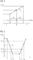
- Dieser Fall ist in
FIG 2 gezeigt, in welcher die relative Leistung PREL über der Zeit t aufgetragen ist. Bis zum Zeitpunkt t1 ist der Istwert PI im Wesentlichen konstant und liegt im oberen Leistungsbereich 0, in welchem die HCO aktiv ist. Zwischen t1 und t3 fällt PI rasant ab, bis ein Wert unterhalb des unteren Schwellwerts PU erreicht ist. Beim Unterschreiten des Grenzwerts PG im Übergangsbereich M zum Zeitpunkt t2 wird dabei die Spaltminimierung abgeschaltet. Zwischen t3 und t4 bleibt der Istwert PI im unteren Bereich U und somit bleibt die HCO inaktiv. Zwischen t4 und t7 steigt der PI stetig an, wobei zum Zeitpunkt t5 der Grenzwert PG erneut überschritten wird. Jedoch löst dies noch keine Aktivierung der HCO in t5 aus, sondern die Spaltminimierung erfolgt erst nach z.B. weiteren 15 min, zum Zeitpunkt t6, obwohl der Istwert PI die ganze Zeit im Bereich M" liegt. Zum Zeitpunkt t7 befindet sich der Istwert PI erneut auf dem Niveau des Ausgangszustands der Gasturbine gemäßFIG 2 . - Würde nach t4 vor dem Aktivieren der HCO der Istwert PI z.B. erneut abfallen, würde dies unter Umständen PMAX aus der letzten Stunde beeinflussen, was wiederum zu einem neuen Grenzwert PG führen könnte.
Claims (10)
- Verfahren zur Steuerung einer Spaltminimierung eines einstellbaren Spalts zwischen einem Rotor und einem Gehäuse einer Gasturbine, wobei die Gasturbine eine, insbesondere hydraulische, Spalteinstellvorrichtung umfasst, gekennzeichnet durch
folgende Schritte:- mit Hilfe eines Simulationsprogramms wird der Betrieb der Gasturbine bei unterschiedlichen Parametereinstellungen abgebildet und ein Simulationsdatensatz wird erstellt, der die Abhängigkeit der Spaltgröße von einem Betriebsparameter enthält,- anhand vom Simulationsdatensatz werden ein unterer Schwellwert (PU) und ein oberer Schwellwert (PO) für den Betriebsparameter festgelegt,- weiterhin wird für einen Übergangsbereich (M) zwischen dem unteren Schwellwert (PU) und dem oberen Schwellwert (PO) eine Korrelation (F) zwischen dem Betriebsparameter und einem Maximalwert (PMAX) des Betriebsparameters aus dem Simulationsdatensatz extrahiert,- während des Betriebs der Gasturbine wird laufend ein Istwert (PI) des Betriebsparameters ermittelt und mit dem unteren Schwellwert (PU) und dem oberen Schwellwert (PO) verglichen,- und über eine vorgegebene Zeitspanne wird der Maximalwert (PMAX) des Istwertes (PI) bestimmt,wobei beim Vergleich des Istwerts (PI) mit dem unteren Schwellwert (PU) und dem oberen Schwellwert (PO), wenn der Istwert (PI):- unterhalb des unteren Schwellwerts (PU) liegt, die Spaltminimierung deaktiviert wird,- oberhalb des oberen Schwellwerts (PO) liegt, die Spaltminimierung aktiviert wird,- im Übergangsbereich (M) liegt, mit Hilfe des Maximalwerts (PMAX) aus der vorgegebenen Zeitspanne unter Heranziehung der Korrelation (F) ein Grenzwert (PG) für den Betriebsparameter ermittelt wird und die Spaltminimierung aktiviert wird, wenn der Istwert (PI) oberhalb des Grenzwertes (PG) liegt und deaktiviert wird, wenn der Istwert (PI) unterhalb des Grenzwerts (PG) liegt. - Verfahren nach Anspruch 1,
wobei als Betriebsparameter die relative Leistung (PREL) verwendet wird, welche auf die Nennleistung der Gasturbine normiert ist. - Verfahren nach einem der vorhergehenden Ansprüche, wobei die Zeitspanne, in welcher der Maximalwert (PMAX) bestimmt wird, zwischen 20 Minuten und 3 Stunden beträgt, insbesondere zwischen 30 min und 90 min.
- Verfahren nach einem der Ansprüche 2 oder 3,
wobei der untere Schwellwert (PU) bei einer relativen Leistung (PREL) zwischen 30 % und 45 % liegt. - Verfahren nach einem der Ansprüche 2 bis 4,
wobei der obere Schwellwert (PO) bei einer relativen Leistung (PREL) zwischen 50 % und 65 % liegt. - Verfahren nach einem der Ansprüche 2 bis 5,
wobei nach einem Abfall der relativen Leistung (PREL), der von einem Anstieg der relativen Leistung (PREL) gefolgt wird, die Spaltminimierung verzögert aktiviert wird, wenn der Istwert (PI) den Grenzwert (PG) überschreitet. - Verfahren nach einem der vorhergehenden Ansprüche, wobei zwischen dem unteren Schwellwert (PU) und dem oberen Schwellwert (PO) mehrere Stufen für den Maximalwert (PMAX) definiert werden, wobei für die Aktivierung oder Deaktivierung der Spaltminimierung lediglich berücksichtigt wird, welche die höchste Stufe ist, die vom Maximalwert (PMAX) in der Zeitspanne überschritten wurde.
- Verfahren nach einem der vorhergehenden Ansprüche, wobei im Betrieb der Gasturbine das Verfahren kontinuierlich durchgeführt wird.
- Steuervorrichtung zur Durchführung des Verfahrens nach einem der vorhergehenden Ansprüche, umfassend eine, insbesondere hydraulische, Spalteinstellvorrichtung sowie Mittel zur Ermittlung des Istwerts des Betriebsparameters.
- Gasturbine mit einer Steuervorrichtung nach Anspruch 9.
Applications Claiming Priority (3)
| Application Number | Priority Date | Filing Date | Title |
|---|---|---|---|
| DE102018203896 | 2018-03-14 | ||
| EP18176962.1A EP3540182A1 (de) | 2018-03-14 | 2018-06-11 | Verfahren zur steuerung einer spaltminimierung einer gasturbine |
| PCT/EP2019/055994 WO2019175091A1 (de) | 2018-03-14 | 2019-03-11 | Verfahren zur steuerung einer spaltminimierung einer gasturbine |
Publications (2)
| Publication Number | Publication Date |
|---|---|
| EP3704354A1 EP3704354A1 (de) | 2020-09-09 |
| EP3704354B1 true EP3704354B1 (de) | 2022-06-08 |
Family
ID=62599468
Family Applications (2)
| Application Number | Title | Priority Date | Filing Date |
|---|---|---|---|
| EP18176962.1A Withdrawn EP3540182A1 (de) | 2018-03-14 | 2018-06-11 | Verfahren zur steuerung einer spaltminimierung einer gasturbine |
| EP19714116.1A Active EP3704354B1 (de) | 2018-03-14 | 2019-03-11 | Verfahren zur steuerung einer spaltminimierung einer gasturbine |
Family Applications Before (1)
| Application Number | Title | Priority Date | Filing Date |
|---|---|---|---|
| EP18176962.1A Withdrawn EP3540182A1 (de) | 2018-03-14 | 2018-06-11 | Verfahren zur steuerung einer spaltminimierung einer gasturbine |
Country Status (5)
| Country | Link |
|---|---|
| US (1) | US11060412B2 (de) |
| EP (2) | EP3540182A1 (de) |
| JP (1) | JP6861325B2 (de) |
| CN (1) | CN111836947B (de) |
| WO (1) | WO2019175091A1 (de) |
Cited By (1)
| Publication number | Priority date | Publication date | Assignee | Title |
|---|---|---|---|---|
| US20230051737A1 (en) * | 2019-10-14 | 2023-02-16 | Kt Corporation | Apparatus, method, and computer program for executing simulation on basis of digital twin service |
Families Citing this family (4)
| Publication number | Priority date | Publication date | Assignee | Title |
|---|---|---|---|---|
| CN113250759A (zh) * | 2021-04-30 | 2021-08-13 | 上海慕帆动力科技有限公司 | 一种trt间隙调节系统 |
| US11655725B2 (en) | 2021-07-15 | 2023-05-23 | Pratt & Whitney Canada Corp. | Active clearance control system and method for an aircraft engine |
| US12123308B2 (en) | 2022-03-23 | 2024-10-22 | General Electric Company | Clearance control system for a gas turbine engine |
| CN115169048A (zh) * | 2022-07-22 | 2022-10-11 | 东南大学溧阳研究院 | 一种基于多领域组件建模的重型燃气轮机建模方法 |
Family Cites Families (14)
| Publication number | Priority date | Publication date | Assignee | Title |
|---|---|---|---|---|
| US4069662A (en) * | 1975-12-05 | 1978-01-24 | United Technologies Corporation | Clearance control for gas turbine engine |
| US4230436A (en) * | 1978-07-17 | 1980-10-28 | General Electric Company | Rotor/shroud clearance control system |
| US8011883B2 (en) * | 2004-12-29 | 2011-09-06 | United Technologies Corporation | Gas turbine engine blade tip clearance apparatus and method |
| US8177474B2 (en) * | 2007-06-26 | 2012-05-15 | General Electric Company | System and method for turbine engine clearance control with rub detection |
| US8126628B2 (en) * | 2007-08-03 | 2012-02-28 | General Electric Company | Aircraft gas turbine engine blade tip clearance control |
| US8296037B2 (en) * | 2008-06-20 | 2012-10-23 | General Electric Company | Method, system, and apparatus for reducing a turbine clearance |
| US8177476B2 (en) * | 2009-03-25 | 2012-05-15 | General Electric Company | Method and apparatus for clearance control |
| US8342798B2 (en) * | 2009-07-28 | 2013-01-01 | General Electric Company | System and method for clearance control in a rotary machine |
| US8939709B2 (en) * | 2011-07-18 | 2015-01-27 | General Electric Company | Clearance control for a turbine |
| DE102012213016A1 (de) * | 2012-07-25 | 2014-01-30 | Siemens Aktiengesellschaft | Verfahren zur Minimierung des Spalts zwischen einem Läufer und einem Gehäuse |
| US9758252B2 (en) * | 2012-08-23 | 2017-09-12 | General Electric Company | Method, system, and apparatus for reducing a turbine clearance |
| GB201315365D0 (en) * | 2013-08-29 | 2013-10-09 | Rolls Royce Plc | Rotor tip clearance |
| DE102014203318A1 (de) | 2014-02-25 | 2015-08-27 | Siemens Aktiengesellschaft | Verfahren zum Betrieb einer Gasturbine bei aktiver hydraulischer Spalteinstellung |
| US10344614B2 (en) * | 2016-04-12 | 2019-07-09 | United Technologies Corporation | Active clearance control for a turbine and case |
-
2018
- 2018-06-11 EP EP18176962.1A patent/EP3540182A1/de not_active Withdrawn
-
2019
- 2019-03-11 JP JP2020538123A patent/JP6861325B2/ja active Active
- 2019-03-11 WO PCT/EP2019/055994 patent/WO2019175091A1/de not_active Ceased
- 2019-03-11 CN CN201980018689.1A patent/CN111836947B/zh active Active
- 2019-03-11 US US16/976,257 patent/US11060412B2/en active Active
- 2019-03-11 EP EP19714116.1A patent/EP3704354B1/de active Active
Cited By (1)
| Publication number | Priority date | Publication date | Assignee | Title |
|---|---|---|---|---|
| US20230051737A1 (en) * | 2019-10-14 | 2023-02-16 | Kt Corporation | Apparatus, method, and computer program for executing simulation on basis of digital twin service |
Also Published As
| Publication number | Publication date |
|---|---|
| US11060412B2 (en) | 2021-07-13 |
| WO2019175091A1 (de) | 2019-09-19 |
| JP2021507176A (ja) | 2021-02-22 |
| EP3704354A1 (de) | 2020-09-09 |
| US20210003027A1 (en) | 2021-01-07 |
| EP3540182A1 (de) | 2019-09-18 |
| CN111836947B (zh) | 2022-10-28 |
| JP6861325B2 (ja) | 2021-04-21 |
| CN111836947A (zh) | 2020-10-27 |
Similar Documents
| Publication | Publication Date | Title |
|---|---|---|
| EP3704354B1 (de) | Verfahren zur steuerung einer spaltminimierung einer gasturbine | |
| DE4108787C2 (de) | Vorrichtung zum Steuern der einer Gasturbine zugeführten Brennstoffmenge | |
| DE3124782C2 (de) | ||
| DE3153303C2 (de) | Verfahren und Einrichtung zum Begrenzen der bei Belastungsänderungen auftetenden thermischen Beanspruchung einer Dampfturbine | |
| DE69712056T2 (de) | Steuersystem für einen abgasturbolader mit veränderbarer geometrie | |
| DE102007035927A1 (de) | Regelung für eine Gasturbine mit aktiv stabilisiertem Verdichter | |
| DE2927781A1 (de) | Steuerungseinrichtung fuer das spiel zwischen einem rotor und dessen ummantelung | |
| EP2376783A1 (de) | Simulationsgestütztes verfahren zur steuerung bzw. regelung von druckluftstationen | |
| DE102007010768A1 (de) | Verfahren für die Optimierung der Ventilstellung und der Pumpendrehzahl in einem Ventilsystem mit PID-Regelung ohne die Verwendung externer Signale | |
| DE4112848C2 (de) | System zur Regelung der Leerlaufdrehzahl einer Brennkraftmaschine | |
| WO2003023213A1 (de) | Verfahren und vorrichtung zum ansteuern piezobetriebener kraftstoff-einspritzventile | |
| EP2579112A1 (de) | Regeleinrichtung | |
| DE3415165C2 (de) | ||
| DE10016589B4 (de) | Ventileinstellungs-Steuerungsvorrichtung zur Verwendung in einer Brennkraftmaschine | |
| EP3130762B1 (de) | System zur aktiven einstellung einer radialen spaltgrösse und zugehöriges flugzeugtriebwerk | |
| EP2948663A1 (de) | Verfahren und vorrichtung zum steuern einer brennkraftmaschine mit einem variablen verdichtungsverhältnis | |
| DE102009037254A1 (de) | Verfahren und Vorrichtung zum Steuern des Beriebs einer Brennkraftmaschine | |
| DE2320171A1 (de) | Regelanlage fuer ein elektrisches kraftwerk | |
| EP1490735B1 (de) | Verfahren und regler zur adaptiven regelung mindestens einer komponente einer technischen anlage | |
| EP1526268B1 (de) | Verfahren zum Regeln des Druckes in einem Kraftstoffspeicher einer Brennkraftmaschine | |
| EP3080420A1 (de) | Verfahren zur drehzahlregelung einer brennkraftmaschine | |
| EP1431927A1 (de) | Verfahren zur Schätzung der Restlebensdauer einer Vorrichtung | |
| EP0358139B1 (de) | Regelverfahren und Regeleinheit | |
| EP4290087B1 (de) | Verhindern von regelungsbedingten schwingungen der position eines ventilglieds bei einem ventil mit pneumatischem antrieb | |
| BE1032095B1 (de) | Verfahren zum Überwachen |
Legal Events
| Date | Code | Title | Description |
|---|---|---|---|
| STAA | Information on the status of an ep patent application or granted ep patent |
Free format text: STATUS: UNKNOWN |
|
| STAA | Information on the status of an ep patent application or granted ep patent |
Free format text: STATUS: THE INTERNATIONAL PUBLICATION HAS BEEN MADE |
|
| PUAI | Public reference made under article 153(3) epc to a published international application that has entered the european phase |
Free format text: ORIGINAL CODE: 0009012 |
|
| STAA | Information on the status of an ep patent application or granted ep patent |
Free format text: STATUS: REQUEST FOR EXAMINATION WAS MADE |
|
| 17P | Request for examination filed |
Effective date: 20200604 |
|
| AK | Designated contracting states |
Kind code of ref document: A1 Designated state(s): AL AT BE BG CH CY CZ DE DK EE ES FI FR GB GR HR HU IE IS IT LI LT LU LV MC MK MT NL NO PL PT RO RS SE SI SK SM TR |
|
| AX | Request for extension of the european patent |
Extension state: BA ME |
|
| RAP1 | Party data changed (applicant data changed or rights of an application transferred) |
Owner name: SIEMENS ENERGY GLOBAL GMBH & CO. KG |
|
| DAV | Request for validation of the european patent (deleted) | ||
| DAX | Request for extension of the european patent (deleted) | ||
| GRAP | Despatch of communication of intention to grant a patent |
Free format text: ORIGINAL CODE: EPIDOSNIGR1 |
|
| STAA | Information on the status of an ep patent application or granted ep patent |
Free format text: STATUS: GRANT OF PATENT IS INTENDED |
|
| INTG | Intention to grant announced |
Effective date: 20220211 |
|
| GRAS | Grant fee paid |
Free format text: ORIGINAL CODE: EPIDOSNIGR3 |
|
| GRAA | (expected) grant |
Free format text: ORIGINAL CODE: 0009210 |
|
| STAA | Information on the status of an ep patent application or granted ep patent |
Free format text: STATUS: THE PATENT HAS BEEN GRANTED |
|
| AK | Designated contracting states |
Kind code of ref document: B1 Designated state(s): AL AT BE BG CH CY CZ DE DK EE ES FI FR GB GR HR HU IE IS IT LI LT LU LV MC MK MT NL NO PL PT RO RS SE SI SK SM TR |
|
| REG | Reference to a national code |
Ref country code: AT Ref legal event code: REF Ref document number: 1497052 Country of ref document: AT Kind code of ref document: T Effective date: 20220615 Ref country code: CH Ref legal event code: EP |
|
| REG | Reference to a national code |
Ref country code: DE Ref legal event code: R096 Ref document number: 502019004574 Country of ref document: DE |
|
| REG | Reference to a national code |
Ref country code: IE Ref legal event code: FG4D Free format text: LANGUAGE OF EP DOCUMENT: GERMAN |
|
| REG | Reference to a national code |
Ref country code: LT Ref legal event code: MG9D |
|
| REG | Reference to a national code |
Ref country code: NL Ref legal event code: MP Effective date: 20220608 |
|
| PG25 | Lapsed in a contracting state [announced via postgrant information from national office to epo] |
Ref country code: SE Free format text: LAPSE BECAUSE OF FAILURE TO SUBMIT A TRANSLATION OF THE DESCRIPTION OR TO PAY THE FEE WITHIN THE PRESCRIBED TIME-LIMIT Effective date: 20220608 Ref country code: NO Free format text: LAPSE BECAUSE OF FAILURE TO SUBMIT A TRANSLATION OF THE DESCRIPTION OR TO PAY THE FEE WITHIN THE PRESCRIBED TIME-LIMIT Effective date: 20220908 Ref country code: LT Free format text: LAPSE BECAUSE OF FAILURE TO SUBMIT A TRANSLATION OF THE DESCRIPTION OR TO PAY THE FEE WITHIN THE PRESCRIBED TIME-LIMIT Effective date: 20220608 Ref country code: HR Free format text: LAPSE BECAUSE OF FAILURE TO SUBMIT A TRANSLATION OF THE DESCRIPTION OR TO PAY THE FEE WITHIN THE PRESCRIBED TIME-LIMIT Effective date: 20220608 Ref country code: GR Free format text: LAPSE BECAUSE OF FAILURE TO SUBMIT A TRANSLATION OF THE DESCRIPTION OR TO PAY THE FEE WITHIN THE PRESCRIBED TIME-LIMIT Effective date: 20220909 Ref country code: FI Free format text: LAPSE BECAUSE OF FAILURE TO SUBMIT A TRANSLATION OF THE DESCRIPTION OR TO PAY THE FEE WITHIN THE PRESCRIBED TIME-LIMIT Effective date: 20220608 Ref country code: ES Free format text: LAPSE BECAUSE OF FAILURE TO SUBMIT A TRANSLATION OF THE DESCRIPTION OR TO PAY THE FEE WITHIN THE PRESCRIBED TIME-LIMIT Effective date: 20220608 Ref country code: BG Free format text: LAPSE BECAUSE OF FAILURE TO SUBMIT A TRANSLATION OF THE DESCRIPTION OR TO PAY THE FEE WITHIN THE PRESCRIBED TIME-LIMIT Effective date: 20220908 |
|
| PG25 | Lapsed in a contracting state [announced via postgrant information from national office to epo] |
Ref country code: RS Free format text: LAPSE BECAUSE OF FAILURE TO SUBMIT A TRANSLATION OF THE DESCRIPTION OR TO PAY THE FEE WITHIN THE PRESCRIBED TIME-LIMIT Effective date: 20220608 Ref country code: LV Free format text: LAPSE BECAUSE OF FAILURE TO SUBMIT A TRANSLATION OF THE DESCRIPTION OR TO PAY THE FEE WITHIN THE PRESCRIBED TIME-LIMIT Effective date: 20220608 |
|
| PG25 | Lapsed in a contracting state [announced via postgrant information from national office to epo] |
Ref country code: NL Free format text: LAPSE BECAUSE OF FAILURE TO SUBMIT A TRANSLATION OF THE DESCRIPTION OR TO PAY THE FEE WITHIN THE PRESCRIBED TIME-LIMIT Effective date: 20220608 |
|
| PG25 | Lapsed in a contracting state [announced via postgrant information from national office to epo] |
Ref country code: SM Free format text: LAPSE BECAUSE OF FAILURE TO SUBMIT A TRANSLATION OF THE DESCRIPTION OR TO PAY THE FEE WITHIN THE PRESCRIBED TIME-LIMIT Effective date: 20220608 Ref country code: SK Free format text: LAPSE BECAUSE OF FAILURE TO SUBMIT A TRANSLATION OF THE DESCRIPTION OR TO PAY THE FEE WITHIN THE PRESCRIBED TIME-LIMIT Effective date: 20220608 Ref country code: RO Free format text: LAPSE BECAUSE OF FAILURE TO SUBMIT A TRANSLATION OF THE DESCRIPTION OR TO PAY THE FEE WITHIN THE PRESCRIBED TIME-LIMIT Effective date: 20220608 Ref country code: PT Free format text: LAPSE BECAUSE OF FAILURE TO SUBMIT A TRANSLATION OF THE DESCRIPTION OR TO PAY THE FEE WITHIN THE PRESCRIBED TIME-LIMIT Effective date: 20221010 Ref country code: EE Free format text: LAPSE BECAUSE OF FAILURE TO SUBMIT A TRANSLATION OF THE DESCRIPTION OR TO PAY THE FEE WITHIN THE PRESCRIBED TIME-LIMIT Effective date: 20220608 Ref country code: CZ Free format text: LAPSE BECAUSE OF FAILURE TO SUBMIT A TRANSLATION OF THE DESCRIPTION OR TO PAY THE FEE WITHIN THE PRESCRIBED TIME-LIMIT Effective date: 20220608 |
|
| PG25 | Lapsed in a contracting state [announced via postgrant information from national office to epo] |
Ref country code: PL Free format text: LAPSE BECAUSE OF FAILURE TO SUBMIT A TRANSLATION OF THE DESCRIPTION OR TO PAY THE FEE WITHIN THE PRESCRIBED TIME-LIMIT Effective date: 20220608 Ref country code: IS Free format text: LAPSE BECAUSE OF FAILURE TO SUBMIT A TRANSLATION OF THE DESCRIPTION OR TO PAY THE FEE WITHIN THE PRESCRIBED TIME-LIMIT Effective date: 20221008 |
|
| REG | Reference to a national code |
Ref country code: DE Ref legal event code: R097 Ref document number: 502019004574 Country of ref document: DE |
|
| PG25 | Lapsed in a contracting state [announced via postgrant information from national office to epo] |
Ref country code: AL Free format text: LAPSE BECAUSE OF FAILURE TO SUBMIT A TRANSLATION OF THE DESCRIPTION OR TO PAY THE FEE WITHIN THE PRESCRIBED TIME-LIMIT Effective date: 20220608 |
|
| PLBE | No opposition filed within time limit |
Free format text: ORIGINAL CODE: 0009261 |
|
| STAA | Information on the status of an ep patent application or granted ep patent |
Free format text: STATUS: NO OPPOSITION FILED WITHIN TIME LIMIT |
|
| PG25 | Lapsed in a contracting state [announced via postgrant information from national office to epo] |
Ref country code: DK Free format text: LAPSE BECAUSE OF FAILURE TO SUBMIT A TRANSLATION OF THE DESCRIPTION OR TO PAY THE FEE WITHIN THE PRESCRIBED TIME-LIMIT Effective date: 20220608 |
|
| 26N | No opposition filed |
Effective date: 20230310 |
|
| PG25 | Lapsed in a contracting state [announced via postgrant information from national office to epo] |
Ref country code: SI Free format text: LAPSE BECAUSE OF FAILURE TO SUBMIT A TRANSLATION OF THE DESCRIPTION OR TO PAY THE FEE WITHIN THE PRESCRIBED TIME-LIMIT Effective date: 20220608 |
|
| PG25 | Lapsed in a contracting state [announced via postgrant information from national office to epo] |
Ref country code: MC Free format text: LAPSE BECAUSE OF FAILURE TO SUBMIT A TRANSLATION OF THE DESCRIPTION OR TO PAY THE FEE WITHIN THE PRESCRIBED TIME-LIMIT Effective date: 20220608 |
|
| REG | Reference to a national code |
Ref country code: BE Ref legal event code: MM Effective date: 20230331 |
|
| PG25 | Lapsed in a contracting state [announced via postgrant information from national office to epo] |
Ref country code: LU Free format text: LAPSE BECAUSE OF NON-PAYMENT OF DUE FEES Effective date: 20230311 |
|
| REG | Reference to a national code |
Ref country code: IE Ref legal event code: MM4A |
|
| PG25 | Lapsed in a contracting state [announced via postgrant information from national office to epo] |
Ref country code: IE Free format text: LAPSE BECAUSE OF NON-PAYMENT OF DUE FEES Effective date: 20230311 |
|
| PG25 | Lapsed in a contracting state [announced via postgrant information from national office to epo] |
Ref country code: BE Free format text: LAPSE BECAUSE OF NON-PAYMENT OF DUE FEES Effective date: 20230331 |
|
| PG25 | Lapsed in a contracting state [announced via postgrant information from national office to epo] |
Ref country code: BG Free format text: LAPSE BECAUSE OF FAILURE TO SUBMIT A TRANSLATION OF THE DESCRIPTION OR TO PAY THE FEE WITHIN THE PRESCRIBED TIME-LIMIT Effective date: 20220608 |
|
| PG25 | Lapsed in a contracting state [announced via postgrant information from national office to epo] |
Ref country code: BG Free format text: LAPSE BECAUSE OF FAILURE TO SUBMIT A TRANSLATION OF THE DESCRIPTION OR TO PAY THE FEE WITHIN THE PRESCRIBED TIME-LIMIT Effective date: 20220608 |
|
| PGFP | Annual fee paid to national office [announced via postgrant information from national office to epo] |
Ref country code: DE Payment date: 20250327 Year of fee payment: 7 |
|
| PGFP | Annual fee paid to national office [announced via postgrant information from national office to epo] |
Ref country code: FR Payment date: 20250324 Year of fee payment: 7 |
|
| PGFP | Annual fee paid to national office [announced via postgrant information from national office to epo] |
Ref country code: IT Payment date: 20250321 Year of fee payment: 7 Ref country code: GB Payment date: 20250325 Year of fee payment: 7 |
|
| REG | Reference to a national code |
Ref country code: AT Ref legal event code: MM01 Ref document number: 1497052 Country of ref document: AT Kind code of ref document: T Effective date: 20240311 |
|
| PGFP | Annual fee paid to national office [announced via postgrant information from national office to epo] |
Ref country code: CH Payment date: 20250401 Year of fee payment: 7 |
|
| PG25 | Lapsed in a contracting state [announced via postgrant information from national office to epo] |
Ref country code: AT Free format text: LAPSE BECAUSE OF NON-PAYMENT OF DUE FEES Effective date: 20240311 |
|
| PG25 | Lapsed in a contracting state [announced via postgrant information from national office to epo] |
Ref country code: CY Free format text: LAPSE BECAUSE OF FAILURE TO SUBMIT A TRANSLATION OF THE DESCRIPTION OR TO PAY THE FEE WITHIN THE PRESCRIBED TIME-LIMIT; INVALID AB INITIO Effective date: 20190311 |
|
| PG25 | Lapsed in a contracting state [announced via postgrant information from national office to epo] |
Ref country code: HU Free format text: LAPSE BECAUSE OF FAILURE TO SUBMIT A TRANSLATION OF THE DESCRIPTION OR TO PAY THE FEE WITHIN THE PRESCRIBED TIME-LIMIT; INVALID AB INITIO Effective date: 20190311 |