EP3703879B1 - Hydraulischer erweiterbarer verbinder - Google Patents
Hydraulischer erweiterbarer verbinder Download PDFInfo
- Publication number
- EP3703879B1 EP3703879B1 EP18873217.6A EP18873217A EP3703879B1 EP 3703879 B1 EP3703879 B1 EP 3703879B1 EP 18873217 A EP18873217 A EP 18873217A EP 3703879 B1 EP3703879 B1 EP 3703879B1
- Authority
- EP
- European Patent Office
- Prior art keywords
- cylindrical body
- chamber
- connector
- piston
- inner cylindrical
- Prior art date
- Legal status (The legal status is an assumption and is not a legal conclusion. Google has not performed a legal analysis and makes no representation as to the accuracy of the status listed.)
- Active
Links
Images

















Classifications
-
- E—FIXED CONSTRUCTIONS
- E04—BUILDING
- E04B—GENERAL BUILDING CONSTRUCTIONS; WALLS, e.g. PARTITIONS; ROOFS; FLOORS; CEILINGS; INSULATION OR OTHER PROTECTION OF BUILDINGS
- E04B1/00—Constructions in general; Structures which are not restricted either to walls, e.g. partitions, or floors or ceilings or roofs
- E04B1/18—Structures comprising elongated load-supporting parts, e.g. columns, girders, skeletons
- E04B1/26—Structures comprising elongated load-supporting parts, e.g. columns, girders, skeletons the supporting parts consisting of wood
- E04B1/2604—Connections specially adapted therefor
-
- E—FIXED CONSTRUCTIONS
- E04—BUILDING
- E04B—GENERAL BUILDING CONSTRUCTIONS; WALLS, e.g. PARTITIONS; ROOFS; FLOORS; CEILINGS; INSULATION OR OTHER PROTECTION OF BUILDINGS
- E04B1/00—Constructions in general; Structures which are not restricted either to walls, e.g. partitions, or floors or ceilings or roofs
- E04B1/18—Structures comprising elongated load-supporting parts, e.g. columns, girders, skeletons
- E04B1/26—Structures comprising elongated load-supporting parts, e.g. columns, girders, skeletons the supporting parts consisting of wood
- E04B1/2604—Connections specially adapted therefor
- E04B2001/268—Connection to foundations
- E04B2001/2684—Connection to foundations with metal connectors
- E04B2001/2688—Connection to foundations with metal connectors self adjusting, e.g. for compensation of shrinkage
-
- E—FIXED CONSTRUCTIONS
- E04—BUILDING
- E04B—GENERAL BUILDING CONSTRUCTIONS; WALLS, e.g. PARTITIONS; ROOFS; FLOORS; CEILINGS; INSULATION OR OTHER PROTECTION OF BUILDINGS
- E04B1/00—Constructions in general; Structures which are not restricted either to walls, e.g. partitions, or floors or ceilings or roofs
- E04B1/35—Extraordinary methods of construction, e.g. lift-slab, jack-block
- E04B2001/3583—Extraordinary methods of construction, e.g. lift-slab, jack-block using permanent tensioning means, e.g. cables or rods, to assemble or rigidify structures (not pre- or poststressing concrete), e.g. by tying them around the structure
Definitions
- the present invention is generally directed to a tension hold-down system used in walls in light frame construction to resist uplift and to compensate for wood shrinkage in wood frame construction and compression loading.
- a hydraulic fluid power linear actuator employing a cylinder and combined piston and piston-rod assembly of elements to convert a supply of pressurized hydraulic fluid to linear mechanical force or motion is known from US 4,375,181 .
- US 2003/230032 A1 discloses a take up device for a building structure, e.g. hold-down for securing the building structure to a foundation, has a housing secured by fasteners to the building structure, the housing defining a cylindrical chamber containing a piston and fluid, with a piston rod projecting from the housing.
- the piston rod is connected to a foundation anchor, and a fluid passage interconnects portions of the cylindrical chamber at opposite sides of the piston.
- the fluid passage is provided with a one-way valve, which allows the housing to move upwardly relative to the piston, to maintain the tightness of the connection to the anchor bolt, but resists opposite movement of the housing.
- US 8,186,924 discloses a fastener assembly comprising a first cylindrical member disposed within a second cylindrical member. One is movable relative to the other one in a first direction, and locked in a second direction opposite the first direction. A spring is operably attached to the members to urge the one in the first direction.
- the present invention provides a hydraulic expandable connector for taking up a slack in a tie rod in a hold-down system with the features of claims 1 and 4, respectively, as well as a reinforced building wall with the features of claim 10.
- a retainer ring 10 is removably attached to an upper portion of the inner cylindrical body 4 to capture the upper end portion of the spring 8.
- the retainer ring 10 has a plurality of resilient fingers 12 disposed around the periphery of an opening 14 that are received in a circumferential groove 16, which holds the retainer ring 10 attached to the inner cylindrical body 4.
- the retainer ring 10 has a circumferential portion 11 that extends outwardly to capture the upper end of the spring 8.
- the retainer ring 10 is further described in application serial No. 15/265,613, filed 09/14/2016 .
- the outer cylindrical body 6 has a reduced diameter portion 18 to capture the lower end portion of the spring 8.
- the spring 8 urges relative sliding movement between the inner cylindrical body 4 and the outer cylindrical body 6.
- the inner cylindrical body 4 has a reduced diameter portion 20 and another reduced diameter portion 22 with a smaller diameter than the reduced diameter portion 20.
- the reduced diameter portions 20 and 22 are axially adjacent to each other.
- a piston member 24 in the form of a ring or sleeve is disposed within the portion 22.
- a seal 25 disposed within an annular groove 27 in the piston 24 seals the piston to the outer cylindrical body 6.
- a spring 26 urges the piston 24 against a seat 28 on the portion 22.
- Fluid chambers 30 and 32 are disposed on either side of the piston 24.
- a passageway 34 communicates between the chambers 30 and 32.
- the passageway 34 is a gap between the piston 24 and the reduced diameter portion 22 of the inner cylindrical body 4.
- a retainer ring 36 holds the spring 26 in place.
- An endcap 38 is threaded to the outer cylindrical body 6.
- a seal 40 within an annular groove 43 in the endcap 38 seals the fluid chamber 32.
- a seal 42 within an annular groove 45 in the outer cylindrical body 6 seals the fluid chamber 30.
- the upper chamber 30 is bounded by the bottom of the endcap 38, the portion 33 and top of the piston 24 and inner cylindrical body 4.
- the lower chamber 32 is bounded by the portion 33, a shoulder 41 extending radially toward the inner cylindrical body 4, the bottom of the piston 24 and the inner cylindrical body 4.
- the upper chamber 32 and the lower chamber 30 are filled with hydraulic fluid, such as mineral oil, water, etc.
- the piston member 24 functions as a valve, opening or closing the passageway 34.
- the connector 2 is attached to a stud wall by means of a tie rod 44 with a nut 46.
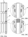
- the tie rod 44 is attached to a wall foundation with an anchor and an anchor rod (see Fig. 28A ).
- a bearing plate 48 may be used to effectively transfer the forces on the connector 2 onto the stud wall.
- a clip 50 is removed after the connector 2 is installed to release the inner cylindrical body 4 relative to the outer cylindrical body 6 so that the spring 8 can move the inner cylindrical body 4 when the stud wall settles downwardly.
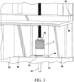
- the connector 2 is shown installed inside a floor system comprising floor joists 52 (one shown) supported on a horizontal framing member, such as a top plate 54 of the stud wall below.
- a sub-floor 56 supported by the floor joist 52, supports a bottom plate 58 of the stud wall above.
- Support blockings 60 provides additional rigidity to the space adjacent the connector 2.
- the connector 2 shown in Fig. 3 may also be replaced by the connector 64 shown in Fig. 6A-7B .
- the connector 2 is shown in an initial set position, prior to expanding to take up a slack in the tie rod 44.
- the upper chamber 32 and the lower chamber 30 are shown in their initial volumes.
- the connector has expanded to take the slack in the tie rod 44.
- the inner cylindrical body 4 has moved upwardly, decreasing the volume of the upper chamber 32 while increasing the volume of the lower chamber 30.
- the expansion of the connector 2 compresses the fluid in the upper chamber 32, causing the fluid to flow through the gap 62 and the passageway 34 into the lower chamber 30.
- the connector 2 has expanded to its fully expanded position.
- the volume of the upper chamber 32 is reduced to zero, with the top end of the piston 24 butting against the bottom end of the endcap 38.
- the volume of the lower chamber 30 is at maximum.
- the actuation spring 8 may be made so that when compressed, it will have enough stored energy to cause upward movement of the inner cylindrical body 4 when a slack develops in the tie rod 44.
- the actuation spring 8 may also be made so that in addition to the energy to expand the connector 2 when a slack develops in the tie rod 44, the spring 8 will have sufficient stored energy to tension the tie rod 44 extending below the connector 2.
- FIG. 6A and 6B another embodiment of a hydraulic expandable connector 64 is disclosed.
- the connector 64 is the same as the connector 2, except the piston 24 is modified as piston 66.
- the piston 66 includes a plurality of passageways 68 in the form of holes arranged around the piston 66 that communicate with the upper chamber 32 and the lower chamber 30.
- fluid from the lower chamber 30 flows through the passageways 68, allowing the piston 66 to move downwardly in a controlled manner, creating a dampening effect.
- the inner cylindrical body 4 moves upwardly under the action of the actuation spring 8.
- the piston actuation spring 26 is compressed by the piston 66, causing the top end of the piston 66 to separate from the seat 28 to create the gap 62 that communicates with the passageway 34.
- the upper chamber 32 decreases in volume, pressurizing the fluid in the chamber while the lower chamber 30 increases in volume, creating a vacuum that causes the fluid from the upper chamber 32 to flow into the lower chamber 30. Some fluid also flows through the passageways 68.
- the connectors 2 and 64 are actuated by the spring 8 when the stud wall moves downwardly due to settlement.
- the spring 8 is disposed outside the connectors 2 and 64.
- a hydraulic expandable connector 70 that uses the building wall displacement for its actuation rather than the spring 8.
- the connector 70 works the same way as the connector 2, except that the inner cylindrical body 4 is threaded to the tie rod 44 and the outer cylindrical body 6 is attached to the wall structure.
- the inner cylindrical body 4 includes an inner threaded portion 72 attached to the tie rod 44.
- the outer cylindrical body 6 is attached to a bearing plate 74 with screws 76.
- the bearing plate 74 is in turn attached to a horizontal framing member or wall structure 78, such as a bottom plate or a cross-member, with screws 80.
- the connector 64 without the spring 8 may be modified as shown for the connector 70 for attachment to the building wall structure.
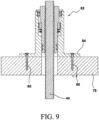
- FIG. 9 an embodiment of a hydraulic expandable connector 82 is disclosed.
- the connector 80 is the same as the connector 70 and works the same way, except that the bearing plate 74 has been integrated into the outer cylindrical body 6 as a flange 84 attached to the wall structure 78.
- the connector 64 without the spring 8 may be modified as shown for the connector 82 for attachment to the building wall structure.
- the piston 24 is sealed to the outer cylindrical body 6 with a plurality of O-ring seals 86 disposed in respective circumferential grooves 88.
- the inner cylindrical body 4 is sealed to the outer cylindrical body 6 with a plurality of O-ring seals 90 disposed in respective circumferential grooves 92.
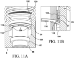
- the connector 94 includes an inner cylindrical body 96 disposed inside the outer cylindrical body 6.
- the inner cylindrical body 96 has a piston portion 98 extending radially and sealed to the outer cylindrical body 6 with the seal 25.
- the piston portion 98 is preferably integral with the rest of the inner cylindrical body 96.
- a piston 100 in the form of a ring is disposed between the inner cylindrical body 96 and the outer cylindrical body 6. Seals 101 in annular grooves 103 in the piston 100 seal the space 108 from the upper chamber 102.
- An upper chamber 102 is bounded by bottom of the piston 100, the top of the piston portion 102, the inner cylindrical body 96 and the portion 33.
- a lower chamber 104 is disposed below the piston portion 98 and bounded by the bottom of the piston portion 98, the portion 33, the inner cylindrical body 96 and the shoulder 41.
- a plurality of openings 105 communicate with the upper chamber 102 and the lower chamber 104.
- the upper chamber 102 and the lower chamber 104 are filled with hydraulic fluid, such as mineral oil, water, etc.
- a one-way valve 107 is associated with each of the openings 105 to allow flow of the fluid from the upper chamber 102 to the lower chamber 104 but not in the opposite direction.
- the endcap 38 includes openings 106 that communicates with the outside and the space 108 to equalize the pressure inside the space 108 when the spring 110 expands to push the piston 100 downwardly when the connector 94 expands in response to the settlement of the building wall in which the connector 94 is installed.
- the fluid in the upper chamber 102 is constantly pressurized by the spring 110.
- the pressure from the upper chamber 102 pushes the fluid into the lower chamber 104 through the openings 105 and the one-way valves 107, pushing the inner cylindrical body 96 upwardly to take up the slack.
- the fluid in the lower chamber 104 is pressurized, closing the one-way valves 107 to prevent fluid flow into the upper chamber 102. Accordingly, the fluid in the lower chamber 104 stops the inner cylindrical body 96 from moving downwardly from the load.
- the principle of operation of the connector 94 may be used for the connector 64, wherein the spring 110 and the air inlet openings 110 are used to actuate the connector.
- the one-way valve 107 may be made of a ring plate 112 made of a single piece material, such as plastic.
- Reed portions 114 are cut into the plate 112 on three sides.
- the reed portions 114 are disposed below the respective openings 105.
- the reed portions 114 when subjected to fluid pressure from the upper chamber 102 via the openings 105 are configured to separate from the plate 112 along the three cut sides to an open position, as shown in Fig. 11B , to allow the fluid to flow into the lower chamber and close position when the lower chamber 104 is pressurized by a downward load on the inner cylindrical body 96.
- a retainer ring 116 held in a circumferential groove 118 supports the ring plate 112.
- a spring 120 is disposed outside the outer cylindrical body 6 in the manner shown for the connectors 2 and 64.
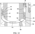
- the plate 112 may be installed into a circumferential groove 122 in the piston portion 98.
- the plate 112 has a radial cut-out 124 to facilitate insertion of the plate 112 into the groove 122.
- the plate 112 has an inside diameter larger than the outside diameter of the cylindrical portion 126 to facilitate insertion of the plate 112 into the groove 122.
- the ends at the cut-out 124 are brought together to temporarily reduce the outside diameter of the plate 112 to clear the inside diameter of the outer edge of the groove 122.
- the ends at the cut-out 124 are released, allowing the plate 112 to spring back to its original size inside the groove 122.
- the reed portions 114 may be attached directly to the underside of the piston portion 98 along one side 128 with standard fastener, such as screws. Each of the reed portions 114 has enough flexibility at the respective side 128 to open or close from the action of the fluid from the upper chamber 102 and the lower chamber 104, respectively. Each of the reed portions 114 is disposed a respective opening 105 (see Figs. 11B and 12 ).
- the reed portions 114 may be attached to a ring plate 130.
- the ring plate 130 has holes 132 aligned with the respective openings 105 in the piston portion 98.
- Each of the reed portions 114 is attached to the ring plate 130 along the side 128, allowing each of the reed portions 114 to away from or toward the respective openings 132 under the action of the fluid from the upper chamber 102 or the lower chamber 104, respectively.
- the ring plate 130 is attached to the underside of the piston portion 98 by standard means, such as screws, adhesives, etc.
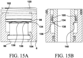
- the one way valve 107 may be implemented by a flat washer 134 held against the underside of the piston portion 98 by a spring 136 held by a retainer ring 138 in a circumferential groove 140.
- the flat washer 134 is urged against the underside of the piston portion 98 by the spring 136, closing the openings 105.
- Fluid from the upper chamber 102 is then forced through the openings 105, pushing the flat washer 134 away from the underside of the piston portion 98 and compressing the spring 136. Fluid will continue to flow until the pressure in the upper chamber 102 and the lower chamber 104 are equalized. The spring 136 then pushes the flat washer against the piston portion 98, thereby closing the openings 105.
- the fluid in the lower chamber 104 resists the load since the fluid is incompressible. Fluid cannot flow to the upper chamber 102 since the openings 105 are closed by the flat washer 134 being pushed by the pressure in the fluid and the spring 136.
- FIG. 16 another embodiment of a hydraulic expandable connector 142 is disclosed.
- the connector 142 includes the inner cylindrical body 4 disposed inside the outer cylindrical body 6.
- the retainer ring 10 shown in Fig. 1 is modified.
- Removable attachment of the retainer ring 10 to the inner cylindrical body 4 is implemented with a circular spring 144 that is received in both the retainer ring 10 and the inner cylindrical body 4 in cooperating circumferential grooves 146 and 148.
- the spring 144 locks the retainer ring 10 in the upward direction but allows the retainer ring 10 to be slipped downwardly.
- the operation of the spring 144 and the grooves 146 and 148 is further described in several patents, such as U.S. Pat. Nos.
- the spring 8 is retained around the outer cylindrical body 6 by a retainer ring 150 and the projecting portion 11.
- the spring 8 urges the inner cylindrical body 4, via the retainer ring 10, in the upward direction to take up any slack that may develop in the tie rod 44 (see Fig. 3 ) due to the building wall shrinkage.
- a deformable seal or piston 152 is disposed between the inner cylindrical body 4 and the outer cylindrical body 6.
- the deformable seal 152 includes a plate portion 154 that opens and closes the passageway 34 between the upper chamber 32 and the lower chamber 30, functioning as a valve as described above in connection with the connector 2.
- the deformable seal 152 also includes a deformable wall portion 156 made of a thin wall section disposed between the top end and the bottom end of the deformable seal 154.
- the inner portion of the deformable seal 154 has a hollowed concave portion 158 to form the deformable wall portion 156 and provides an opening 160 that connects the lower chamber 30 with the hollowed portion 158 and the deformable wall portion 156.
- the upper chamber 32 and the lower chamber 30 are filled with hydraulic fluid, such as mineral oil, water, etc.
- the connector 142 when taking up the slack that develops in the tire rod 44 works the same way as the connector 2. However, when under load, the operation is different.
- the seat 28 When the inner cylindrical body 4 is subjected to an axial downward load, the seat 28 will press on the plate portion 154, sealing the upper chamber 32 from the lower chamber 30.
- the fluid in the lower chamber 30 is subjected to high pressure when the connector 142 is subjected to an axial downward load, deforming the thin and deformable wall portion 156.
- the deformation occurs toward the outer cylindrical body 6, forcing the deformable wall portion 156 into the wall of the outer cylindrical body 6 into a locking engagement.
- the gap 62 (see Fig.
- the seal 162 advantageously keeps the high pressure fluid in the lower chamber 30 from leaking into the abutting surfaces between the outer cylindrical body 6 and the deformable seal 152 so that pressure behind the deformable wall portion 156 is less than the pressure in the hollowed portion 158.
- the deformation of the deformable wall portion 156 advantageously provides a permanent seal that becomes tighter as more load is exerted on the inner cylindrical body 4.
- the deformable seal 152 advantageously makes the connector 142 fail-safe under load. In the event the seals 164 fail, the inner cylindrical body 4 will hold the load due to the locking engagement of the deformable seal 152 with the wall of the outer cylindrical body 6.
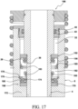
- FIG. 17 another embodiment of a hydraulic expandable connector 1 is disclosed.
- the connector 166 is similar to the connector 142, except that the seals 164 have been replaced by a deformable seal 168 similar in construction to the deformable seal 152.
- the deformable seal 168 has a base portion 170 engaged against an inner shoulder 172 of the outer cylindrical body 6.
- the deformable seal 168 has a deformable wall portion 174 abutting the inner cylindrical body 4.
- a retainer ring 176 in a circumferential groove 178 holds a spring 180 that urges the base portion 170 against the should 172.
- a lower chamber 182 filled with hydraulic fluid is bounded by the deformable seals 152 and 168 and the inner cylindrical body 4 and outer cylindrical body 6.
- the upper chamber 32 is also filled with hydraulic fluid.
- FIG. 18 another embodiment of a hydraulic expandable connector 184 is disclosed.
- the connector 184 is identical to the connector 166 except that the springs 26 and 180 are replaced with a single spring 186.
- the spring 186 pushes the upper deformable seal 152 as the inner cylindrical body 4 moves upwardly to take up slack in the tie rod 44 caused by the building wall settlement.
- the spring 186 also keeps the lower deformable seal 168 in contact with the shoulder 172. Seals 188 in annular grooves 189 in the upper and lower deformable seals 152 and 168 are disposed outside the high pressure fluid (under load) lower chamber 182.
- FIG. 19 another embodiment of a hydraulic expandable connector 190 is disclosed.
- the connector 190 is similar to the connector 184 except that the lower deformable seal 168 has been integrated into the outer cylindrical body 192.
- the outer cylindrical body 192 has a deformable wall portion 194 extending from a shoulder 196.
- the connector 190 works in the same way as the connector 184 during expansion and under load.
- FIG. 20 another embodiment of a hydraulic expandable connector 198 is disclosed.
- the connector 198 is similar to the connector 2, except that the inner cylindrical body 4 is provided with internal threads 200 for threading to the tie rod 44 and the retainer ring 10 has been replaced with a washer 202.
- the tie rod 44 is attached to a wall foundation with an anchor and an anchor rod (see Fig. 28A ).
- a nut 204 compresses the spring 8 via the washer 202 and retainer ring 206 held in a circumferential groove 208 in the outer cylindrical body 6.
- the spring 8 is compressed during installation.
- a bearing plate 210 is disposed on a horizontal metal framing member 220 (part of the building wall) to advantageously distribute the load over a larger area than the footprint of the connector 198.
- Hydraulic seal 221 in annular groove 27 in the piston 24 is used instead of an O-ring for greater sealing power.
- Hydraulic seal 223 in annular groove 45 in the outer cylindrical body 6 is also used instead of an O-ring for greater sealing power. Hydraulic seals are typically used in reciprocating motion applications, such as piston-cylinder assemblies.
- the connector 198 works the same way as the connector 2 when subjected to a downward load.
- FIG. 21 another embodiment of a hydraulic expandable connector 222 is disclosed.
- the connector 222 is similar to the connector 198, except that the spring 8 is replaced with a conical spring 224 and the washer 202 is not used.
- the conical spring 224 is compressed by the nut 204 and presses on the outer cylindrical body 6 via the endcap 38, which has been provided with a collar portion 226 to center the bottom end of the spring 224 over the endcap 38.
- the outer cylindrical body 6 moves downwardly from the action of the spring 224 while the inner cylindrical body 4 stays attached to the tie rod 44.
- the connector 222 works the same way as the connector 2 when subjected to a downward load.
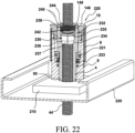
- FIG. 22 another embodiment of a hydraulic expandable connector 228 is disclosed.
- the connector 228 is similar to the connector 2, except that the inner cylindrical body 4 is modified to accept a split cylindrical nut 230 threadedly attached to the tie rod 44.
- the tie rod 44 is attached to a wall foundation with an anchor and an anchor rod (see Fig. 28A ).
- the inner cylindrical body 4 an enlarged opening 232 that narrows into a conical opening 234.
- the cylindrical split nut 230 is made up of preferably four equal segments 236 with inner threads that mate with the threads of the tie rod 44.
- the segments 236 are bundled together by a circular spring 235.
- the cylindrical split nut 230 has conical portions 237 that mate with the conical opening 234.
- a retainer ring 238 is threaded to a threaded portion 240 of the opening 232.
- the retainer ring 238 compresses a spring 242 to urge the cylindrical split nut 230 downwardly into the conical opening 234.
- the retainer ring 238 has an unthreaded opening 244 allows the tie rod 44 to move axially through the opening 244.
- the clip 50 is removed after the connector is installed to allow the inner cylindrical body 4 to move relative to the outer cylindrical body 6.
- the cylindrical split nut 230 advantageously reduces the amount of time of installation since the segments 236 are simply dropped into the opening 232 instead of being screwed down from the end of the tie rod 44 as with a standard nut.
- the opening 232 is larger than the diameter of the cylindrical portion of the cylindrical split nut 230 so that the segments 236 can radially expand and disengage from the threads of the tie rod as the connector 228 is slid down the tie rod during installation.
- Split nuts are disclosed in U.S. Pat. Nos. 9303399 and 9222251 and application serial No. 15/265613 .
- the conical opening 234 in the inner cylindrical body 4 of the connector 228 is modified to work with a hexagonal split nut 246.
- a washer 248 distributes the force of the spring 242 over the segments 250 of the split nut 246.
- the opening 232 has a rounded outer edge 252 that cooperates with a complementarily rounded surface 254 that serve to draw the segments 250 into threaded engagement with the threads of the tie rod 44.
- the connector 2 or the connector 64 (see Fig. 6A ) is shown installed inside a wall.
- the connector 2 is shown in the unactuated state since the locking clip 50 has not been removed yet.
- the clip 50 is removed to activate the spring 8 and hence the connector 2.
- the tie rod 44 is cut at the end 256 just above the nut 46 to facilitate installation of the connector 2, which is slid down the tie rod 44 at the end 256.
- a coupling 258 joins the tie rod 44 to another tie rod 260 to continue the run.
- the bearing plate 48 sits on top of a horizontal framing member, such as a base plate 262 supporting a plurality of studs 264.
- a sub-floor sheet 266 is below the top plate 258.
- the tie rod 44 is attached to a wall foundation with an anchor and an anchor rod (see Fig. 28A ).
- the connector 2 or the connector 64 (not shown but see Fig. 6A ) is shown installed over a horizontal framing member, such as a wood bridge member 268 or a metallic bridge member 270 supported on top of jack or reinforcement studs 272 attached to king studs 274.
- the inner cylindrical body 4 is threadedly attached to the tie rod 44.
- the tie rod 44 is attached to a wall foundation with an anchor and an anchor rod (see Fig. 28A ).
- the spring 8 moves the outer cylindrical body 6 as the wall shrinks or settles downwardly.
- the clip 50 is removed to activate the connector 2.
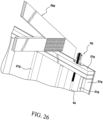
- the connector 82 (see Fig. 9 ) is attached to a horizontal framing member, such as a double top plate 276 supported by a plurality of studs 278.
- a plurality of roof rafters 280 (one shown) is supported by the double top plate 276.
- the tie rod 44 is attached to a wall foundation with an anchor and an anchor rod (see Fig. 28A ).
- FIG. 27 two connectors 2 are shown attached in tandem inside a wall over the bottom plate 262.
- the connectors 2 are installed on either side of the tie rod 44.
- the tie rod 44 is attached to a wall foundation with an anchor and an anchor rod (see Fig. 28A ).
- Threaded rods 282 attached to a base plate 284 guide the respective connectors 2 as they expand.
- a top plate 286 distributes the load from the tie rod 44 over the two connectors 2.
- Use of the tandem arrangement advantageously allows the use of the connectors 2 with smaller axial openings than the diameter of the tie rod 44. With smaller axial openings, the overall outside diameter of the connectors 2 is advantageously reduced to fit in smaller spaces.
- the load is also distributed over the two connectors 2, advantageously requiring less load capability for each connector.
- Swivel washers 288 with complementary concave surface 290 and convex surface 292 advantageously allow the tie rod 44 to be misaligned from the vertical while keeping the contact surface 294 of the swivel washers flat on the contact surface 296 of the top plate 286.
- the nut 46 holds applies tension on the tie rod 44.
- the swivel washers 288 and the tandem arrangement of the connectors 2 are also disclosed in application serial No. 15/265,613, filed 09/14/2016 . It should be understood that other embodiments of the connector disclosed herein, such as the connector 64, 70, 82, 94, 142, 166, 184, 190, 222, 228, etc., may be used in the tandem configuration.
- a three-level wall 297 is shown anchored to a foundation 298 with two connectors 2.
- the wall is standard construction.
- Each section 299 of the wall includes a bottom plate 300, a plurality of studs 302 and a double top plate 304.
- Floor joists 306 between the lower wall section and the upper wall section are supported on the respective double top plates 304.
- Roof rafters (one shown) 306 are supported by the top plates of the top wall section.
- An anchor rod 308 is attached to an anchor 310 embedded in the foundation 298.
- a tie rod 320 with threaded end portions and an unthreaded portion in between is attached to the anchor rod with a coupling 322.
- the unthreaded portions of the tie rods 302 are disposed in the openings in the double top plates 304 and bottom plates 300 to advantageously allow the floors to shrink downwardly without snagging and bowing the tie rods. In this manner, the tie rods 320 will have no slack.
- the upper connector 2 as shown in Fig. 28B has a longer travel length of expansion than the lower connector 2 as shown in Fig. 28C , since the upper connector 2 is to accommodate the cumulative shrinkage of the floors below.
- the inner cylindrical body 4 of the connector 2 of Fig. 28B has a convex upper edge surface 323 that cooperates with a swivel washer with a complementary shaped bottom surface 325 to advantageously allow the misalignment from the vertical of the tie rod 320. Since the connector 2 of Fig. 28B is located furthest from the foundation 298, small misalignment or displacement as measured in arc length from the vertical of the tie rod 320 grows by the time it reaches to the position of the connector 2 on the third level of the wall 297.
- FIG. 29A, 29B and 29C the upper connector 2 shown in Fig. 28A is replaced with the connector 64 (see Fig. 6A ) .
- the connector 64 is disposed on top of a connector 324, which is similar to the connector 70, except that the outer cylindrical body 326 is not attached to the bearing plate 48.
- the bearing plate 74 is also not attached to the wall structure 78.
- the inner cylindrical body 328 is threaded to the tie rod 77 and extends into the connector 64, engaging the inner cylindrical body 4 of the connector 64.
- the outer cylindrical body 6 of the connector 64 engages the endcap 38 of the connector 324.
- the nut 46 attaches the connector 64 to the tie rod 44.
- the tie rod 44 is attached to a wall foundation with an anchor and an anchor rod (see Fig. 28A ).
- the spring 8 is used to actuate both connectors 4 and 64.
- the inner cylindrical body 328 moves upwardly relative to the wall structure 78, pushing the inner cylindrical body 4 upwardly.
- the spring 8 then pushes the outer cylindrical bodies 6 and 326 downwardly to take up the amount of shrinkage. Even after the lower connector 324 has bottomed out or failed, the upper connector 64 will still function to dampen any load on the tie rod 44.
- FIG. 31 another embodiment of a hydraulic expandable connector 330 is disclosed.
- the connector 330 is disposed inverted below and hanging from the wall structure 78.
- the connector 330 has an inner cylindrical body 332 within an outer cylindrical body 334.
- a piston portion 336 preferably integral with the inner cylindrical body 332, extends radially outwardly and slidably engages an inner wall 338 of the outer cylindrical body 334.
- the piston portion 336 defines an upper chamber 340 and a lower chamber 342 between the inner wall 338 and the inner cylindrical body 332.
- the chambers 340 and 342 are filled with hydraulic fluid, such as mineral oil, water, etc.
- a plurality of openings 344 communicate with upper chamber 340 and the lower chamber 342.
- a seal 346 preferably an O-ring, disposed within an annular groove 347 in the piston portion 336, seals the piston portion 336 with the inner wall 338.
- Another outer cylindrical body 348 is threaded to the other cylindrical body 334.
- Seals 350 preferably O-rings, seal the inner cylindrical body 332 to the outer cylindrical bodies 334 and 348.
- the inner cylindrical body 332 is threaded to the tie rod 44.
- the tie rod 44 is attached to a wall foundation with an anchor and an anchor rod (see Fig. 28A ).
- a spring 352 disposed within the upper chamber 340 pushes the outer cylindrical bodies 334 and 348 against the bearing plate 48. The spring 352 prevents the outer cylindrical body 334 and the bearing plate 48 from falling downwardly due to gravity.
- the wall structure 78 moves with the wall, pushing the outer cylindrical body 334 downwardly, thereby pressurizing the fluid in the upper chamber 340.
- the fluid then flows through the openings 344 in a predetermined rate, depending on the size and number of the openings 344. A smaller size of the opening 344 will cause the fluid to flow slower than a larger size. A greater number of the openings 344 will cause the fluid to flow faster than a lesser number of the openings 344. Accordingly, the rate of downward movement of the wall may be predetermined.
- the tie rod 44 When there is an uplift force on the wall, the tie rod 44 is pulled upwardly (tension force), causing the inner cylindrical body 332 to move upwardly, thereby pressurizing the upper chamber 340.
- the fluid in the upper chamber 340 flows through the openings 344 in a predetermined rate to dampen the upward movement of the tie rod 44. Accordingly, the wall cannot move faster than the rate of movement of the outer cylindrical body 334 or the inner cylindrical body 332.
- the connector 330 shown in Fig. 31 is modified as connector 354 wherein the seals 344 and 350 are replaced with standard hydraulic seals 356 and 358, also known as rod seals. Hydraulic seals are typically used in reciprocating motion applications, such as piston-cylinder assemblies. The hydraulic seals 356 and 358 can withstand higher pressures than a typical O-ring seal.
- the connector 354 shown in Fig. 32 is modified as a hydraulic expandable connector 360 wherein the spring 352 is not used.
- the friction between the inner cylindrical body 332 and the seals 358 is sufficient to keep the outer cylindrical bodies 334 and 348 and the bearing plate 48 from falling under their own weight.
- the force applied to the outer cylindrical bodies 334 and 348 as the wall shrinks is enough to overcome the friction of the seals 358 and move the outer cylindrical bodies 334 and 348.
- the connector 360 is modified as a hydraulic expandable connector 362 wherein the outer cylindrical body 334 and the other outer cylindrical body 348 are modified as outer cylindrical bodies 364 and 366, respectively.
- the outer cylindrical body 366 has a cylindrical portion 368 disposed between the inner cylindrical body 332 and the outer cylindrical body 365.
- a seal 370 preferably an O-ring, seals the cylindrical portion 368 against the outer cylindrical body 364.
- the outer cylindrical body 366 has a threaded cylindrical portion 372 that mates with a corresponding threaded cylindrical portion 374 of the outer cylindrical body 364.
- the threaded cylindrical portions 372 and 374 are advantageously disposed below the lower chamber 342 to provide a stronger connection between the outer cylindrical bodies 364 and 366.
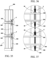
- the building wall 297 shown in Fig. 28A is further equipped with the connectors 330.
- the connectors 354 or 362, which are variants of the connectors 330 may also be used.
- the connectors 330 are designed to move downward slowly to allow for shrinkage/settling of the wall 397. If the wall 297 attempts to move downward faster than the speed the connectors 330 are designed for, the connectors 330 will slow down the downward movement of the wall.
- the connectors 330 are mounted in the downward orientation as shown to slow down or resist the downward/compressive forces in the structure and channel those forces to the tie rods 320, turning the tie rods into both a tension and compression member instead of a tension member only.
- the upper connector 330 shown in Fig. 36 has a greater travel length than the lower connector 330 shown in Fig. 37 to account for the cumulative shrinkage of the floors below.
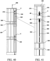
- the upper connector 2 shown in Fig. 39 is disposed on a cross member 376 supported on top of a pair of reinforcement studs 380.
- the connectors 330 function in the same way as those shown in Fig. 35 , slowing down or resisting the downward/compressive forces in the structure and channel those forces to the tie rods 320, turning the tie rods into both a tension and compression member instead of a tension member only.
- the upper connector 330 is installed directly below the cross member or bridge member 376.
- the connectors 330 function to dampen the downward movement of the wall 297 as it shrinks.
- the cross member 376 is operably sandwiched between the reinforcement studs 380 and 379.
- the reinforcement studs 380 and 379 are operably attached to the studs 302 to help transfer the load from the tie rod 320 to the cross member 376 and the studs.
- a damping coupling 378 is disclosed.
- the coupling 378 has a housing 381 with a closed internal chamber 382 filled with hydraulic fluid, such as mineral oil, water, etc.
- the housing 380 is preferably made of one body 384 threaded to another body 386.
- a piston 388 is disposed inside the chamber 382 and slidable between one end of the chamber 382 to the other end.
- the chamber 382 is divided into one chamber 390 on one side of the piston 388 and another chamber 392 on the other side of the piston 388. Passageways 394 allow the fluid in the chamber to flow from one chamber 390 to the other chamber 392 or vice versa.
- the piston 388 includes a rod portion 396 extending outside the housing 380 and threadedly attached to the tie rod 44 through a threaded opening in the rod portion 396.
- the other body 386 is threadedly attached to another tie rod 44 through a threaded opening in the body 386.
- a seal 398 such as an O-ring disposed inside an annular groove 400 in the body 384, seals the chamber 390 between the rod portion 396 and the body 384.
- a seal 402 such as an O-ring disposed in annular groove 404 in the piston 388, seals the chamber 390 from the other chamber 392 so that fluid flow is restricted only through the passageways 394.
- the damping coupling 378 is a non-rigid coupling joining two tie rods 44 together.
- the tie rods 44 are allowed to move axially at a controlled rate within a designed maximum distance dictated by the length of the chamber 382.
- the coupling 378 becomes rigid in one direction.
- the passageways 394 allow the piston 388 to move through the fluid no faster than the fluid flow through the passageways 394, thereby providing a damping effect on the compressive or tensile forces acting on the tie rods 44. Damage due to excessive forces is advantageously avoided or lessened.
- the damping coupling 378 is modified as damping coupling 404 with the addition of a spring 406 disposed within the chamber 390.
- the spring 406 advantageously generates a force to pull the two tie rods 44 together.
- the spring 406 further provides additional tensioning in the tie rods 44 as the wall shrinks.
Landscapes
- Engineering & Computer Science (AREA)
- Architecture (AREA)
- Physics & Mathematics (AREA)
- Electromagnetism (AREA)
- Civil Engineering (AREA)
- Structural Engineering (AREA)
- Buildings Adapted To Withstand Abnormal External Influences (AREA)
- Joining Of Building Structures In Genera (AREA)
- Actuator (AREA)
- Clamps And Clips (AREA)
- Fluid-Damping Devices (AREA)
Claims (10)
- Hydraulisch expandierbarer Verbinder (2; 142) zum Aufnehmen eines Durchhangs in einer Zugstange in einem Niederhaltesystem, umfassend:a) einen inneren zylindrischen Körper (4), der in einem äußeren zylindrischen Körper (6) angeordnet ist, wobei der innere zylindrische Körper (4) eine erste und eine zweite äußere zylindrische Wandfläche aufweist, die von einer ersten bzw. zweiten inneren zylindrischen Wandfläche des äußeren zylindrischen Körpers (6) beabstandet sind und diesen gegenüberliegen,b) eine erste Betätigungsfeder (8), die funktionsfähig an dem inneren zylindrischen Körper (4) und dem äußeren zylindrischen Körper (6) angebracht ist, um eine Relativbewegung zwischen dem inneren zylindrischen Körper (4) und dem äußeren zylindrischen Körper (6) zu erzwingen, so dass sich der Verbinder (2; 142) axial expandiert, um den Durchhang aufzunehmen,c) eine erste Kammer (30) und eine zweite Kammer (32), die jeweils zwischen der ersten und der zweiten äußeren zylindrischen Wandfläche des inneren zylindrischen Körpers (4) und der ersten und der zweiten inneren zylindrischen Wandfläche des äußeren zylindrischen Körpers (6) angeordnet sind,d) einen ersten Durchgang (34), der eine Verbindung zwischen der ersten Kammer (30) und der zweiten Kammer (32) herstellt, unde) ein Ventil (24; 152), das funktionsfähig in dem ersten Durchgang (34) angeordnet ist, wobei das Ventil (24; 152) eine geschlossene Position und eine offene Position hat, wobei das Ventil (24; 152) in der offenen Position ist, wenn sich der Verbinder (2; 142) expandiert, um zu ermöglichen, dass Fluid von der ersten Kammer (30) zu der zweiten Kammer (32) strömt, wobei das Ventil (24; 152) in der geschlossenen Position ist, wenn der Verbinder (2; 142) einer axialen Last ausgesetzt ist, um das Fluid in der zweiten Kammer (32) unter Druck zu setzen und die Last zu absorbieren.
- Hydraulisch expandierbarer Verbinder (2; 142) nach Anspruch 1, wobei das Ventil (24; 152) einen Kolben (24) umfasst, der zwischen dem inneren zylindrischen Körper (4) und dem äußeren zylindrischen Körper (6) angeordnet ist, wobei der erste Durchgang (34) vorzugsweise einen Spalt zwischen dem Kolben (24) und dem inneren zylindrischen Körper (4) umfasst.
- Hydraulisch expandierbarer Verbinder (2; 142) nach Anspruch 2, wobei:a) der innere zylindrische Körper (4) eine Schulter (28) aufweist, die mit einem Eingang des Durchgangs in Verbindung steht,b) der Kolben (24) eine erste Position einnimmt, die an der Schulter angreift, um den Eingang zum ersten Durchgang (34) zu schließen, undc) der Kolben (24) eine zweite, von der Schulter entfernte Position einnimmt, um den Eingang zum Durchgang zu öffnen, vorzugsweisewobei der innere zylindrische Körper (4) eine ringförmige Ausnehmung aufweist und der Kolben (24) innerhalb der ringförmigen Ausnehmung angeordnet ist und/oderwobei eine zweite Feder (26) den Kolben (24) zum Eingriff mit der Schulter drückt.
- Hydraulisch expandierbarer Verbinder (94) zum Aufnehmen eines Durchhangs in einer Zugstange in einem Niederhaltesystem, umfassend:a) einen inneren zylindrischen Körper (96), der innerhalb eines äußeren zylindrischen Körpers (6) angeordnet ist, wobei der innere zylindrische Körper (96) eine erste und eine zweite äußere zylindrische Wandfläche aufweist, die von einer ersten bzw. der zweiten inneren zylindrischen Wandfläche des äußeren zylindrischen Körpers (6) beabstandet sind und diesen gegenüberliegen,b) einen ersten Kolben (100), der zwischen dem inneren zylindrischen Körper (96) und dem äußeren zylindrischen Körper (6) verschiebbar ist,c) eine erste Feder (110), die funktionsfähig an dem äußeren zylindrischen Körper (6) befestigt ist, um den ersten Kolben (100) axial zu drücken,d) eine erste Kammer (102) und eine zweite Kammer (104), die jeweils zwischen der ersten und der zweiten äußeren zylindrischen Wandfläche des inneren zylindrischen Körpers (96) und der ersten und der zweiten inneren zylindrischen Wandfläche des äußeren zylindrischen Körpers (6) angeordnet sind,e) einen ersten Durchgang (105), der eine Verbindung zwischen der ersten Kammer (102) und der zweiten Kammer (104) herstellt,f) ein Ventil (107), das funktionsfähig in dem ersten Durchgang (105) angeordnet ist, wobei das Ventil (107) eine geschlossene Position und eine offene Position hat, wobei sich das Ventil (107) in der offenen Position befindet, wenn sich der Verbinder (94) expandiert, um zu ermöglichen, dass Fluid von der ersten Kammer (102) zu der zweiten Kammer (104) strömt, wobei sich das Ventil (107) in der geschlossenen Position befindet, wenn der Verbinder (94) einer axialen Belastung ausgesetzt ist, undg) die erste Feder (110) das Fluid in der ersten Kammer (102) unter Druck setzt, um zu bewirken, dass das Fluid durch den Durchgang (105) in die zweite Kammer (104) strömt und den inneren zylindrischen Körper (96) axial wegbewegt, um den Verbinder (94) zu expandieren.
- Hydraulisch expandierbarer Verbinder (2; 94; 142) nach Anspruch 1 oder 4,wobei das Volumen der ersten Kammer (30; 102) abnimmt und das Volumen der zweiten Kammer (32; 104) zunimmt, wenn sich der Verbinder axial expandiert, und/oderwobei die erste Feder (8; 110) im Inneren des äußeren zylindrischen Körpers (6) angeordnet ist.
- Hydraulisch expandierbarer Verbinder (2; 142) nach Anspruch 2, der ferner einen zweiten Durchgang aufweist, der mit der ersten Kammer (30) und der zweiten Kammer (32) in Verbindung steht, wobei der zweite Durchgang ständig offen ist, damit Fluid zwischen der ersten Kammer (30) und der zweiten Kammer (32) strömen kann, selbst wenn der erste Durchgang (34) geschlossen ist, wobei der zweite Durchgang vorzugsweise eine Anzahl von Löchern durch den Kolben aufweist.
- Hydraulisch expandierbarer Verbinder (2; 94; 142) nach Anspruch 1 oder 4, ferner umfassend:a) einen Kolben oder zweiten Kolben, der einen Teil des inneren zylindrischen Körpers (4; 96) bildet, undb) der Kolben oder zweite Kolben zwischen der ersten Kammer (30; 102) und der zweiten Kammer (32; 104) angeordnet ist,wobei der erste Durchgang vorzugsweise durch den Kolben oder den zweiten Kolben hindurch angeordnet ist,wobei das Ventil vorzugsweise an einem Ende des ersten Durchgangs angeordnet ist,wobei wiederum mehr bevorzugt wird:a) der erste Durchgang umfasst eine Anzahl von Öffnungen durch den Kolben oder den zweiten Kolben undb) das Ventil umfasst eine Anzahl von Einwegventilen, die den jeweiligen Öffnungen funktionsfähig zugeordnet sind,
vorzugsweise mita) die Anzahl der Einwegventile besteht aus einer Ringplatte mit in die Ringplatte eingeschnittenen Zungenabschnitten,b) die Zungenabschnitte sind funktionsfähig mit den jeweiligen Öffnungen verbunden undc) die Zungenabschnitte reagieren auf den Flüssigkeitsdruck, um die jeweiligen Öffnungen zu öffnen oder zu schließen, und/odera) wobei die mehreren Einwegventile Zungen umfassen, die an den jeweiligen Öffnungen funktionsfähig am Kolben oder zweiten Kolben angebracht sind, undb) die Zungen auf Flüssigkeitsdruck reagieren, um die jeweiligen Öffnungen zu öffnen oder zu schließen, und/odera) die mehreren Einwegventile eine flache Unterlegscheibe umfassen, die über den Öffnungen angeordnet ist, undb) eine zweite Feder, die die flache Unterlegscheibe gegen die Öffnungen drückt, wobei die zweite Feder in Reaktion auf den Flüssigkeitsdruck in den Öffnungen komprimierbar ist und die flache Unterlegscheibe von den Öffnungen wegdrückt. - Hydraulisch expandierbarer Verbinder (142) nach Anspruch 1, wobei
das Ventil (152) einen verformbaren Wandabschnitt (156) aufweist, der sich in eine Innenwand des äußeren zylindrischen Körpers (6) verformt, wenn der Verbinder einer axialen Belastung ausgesetzt wird, um den inneren zylindrischen Körper mit dem äußeren zylindrischen Körper (6) zu verriegeln. - Hydraulisch expandierbarer Verbinder (142) nach Anspruch 8, wobei das Ventil einen Kolben (152) umfasst, der zwischen der ersten Kammer (30) und der zweiten Kammer (32) angeordnet ist,vorzugsweise wobei:a) die zweite Kammer (32) unter einem höheren Druck als die erste Kammer (30) steht, wenn der Verbinder unter Last steht, undb) der Kolben (152) einen ersten ausgehöhlten Abschnitt (158) aufweist, der mit der zweiten Kammer (32) in Verbindung steht, wobei der erste ausgehöhlte Abschnitt (158) einen ersten dünnen Wandabschnitt aufweist, der in die Innenwand des äußeren zylindrischen Körpers eingreift, wobei der verformbare Wandabschnitt (156) den ersten dünnen Wandabschnitt aufweist,vorzugsweise weiter umfassend:a) eine verformbare Dichtung, die in der zweiten Kammer angeordnet ist, undb) die verformbare Dichtung enthält einen zweiten ausgehöhlten Abschnitt, der mit der zweiten Kammer in Verbindung steht, wobei der zweite ausgehöhlte Teil einen zweiten dünnen Wandabschnitt enthält, der mit einer Innenfläche des inneren zylindrischen Körpers in Eingriff steht,wobei die verformbare Dichtung vorzugsweise in den äußeren zylindrischen Körper integriert ist.
- Verstärkte Gebäudewand mit:a) einem horizontalen Wandrahmenelement (78),b) einer Lagerplatte (48), die von dem Wandrahmenelement (78) getragen wird,c) einer Zugstange (44), die funktionsfähig an einem Fundament der Wand befestigt ist und sich durch die Lagerplatte (48) erstreckt,d) einem ersten hydraulisch expandierbaren Verbinder (324) zum Aufnehmen eines Durchhangs in der Zugstange (44), wobei der erste hydraulisch expandierbare Verbinder (324) an der Lagerplatte (48) angeordnet ist und die Zugstange (44) sich durch den ersten hydraulisch expandierbaren Verbinder (324) erstreckt,e) einem zweiten hydraulisch expandierbaren Verbinder (64) zum Aufnehmen eines Durchhangs in der Zugstange (44), wobei der zweite hydraulisch expandierbare Verbinder (64) oberhalb des ersten hydraulisch expandierbaren Verbinders (324) angeordnet ist, wobei sich die Zugstange (44) durch den zweiten hydraulisch expandierbaren Verbinder (64) erstreckt, wobei die Zugstange (44) betriebsmäßig mit dem zweiten hydraulisch expandierbaren Verbinder (64) verbunden ist,f) wobei der erste hydraulische Verbinder (324) einen ersten inneren zylindrischen Körper (328) umfasst, der in einem ersten äußeren zylindrischen Körper (326) angeordnet ist, eine erste Kammer und eine zweite Kammer, die zwischen einer Außenwandfläche des ersten inneren zylindrischen Körpers (328) und einer Innenwandfläche des ersten äußeren zylindrischen Körpers (326) angeordnet sind, einen ersten Durchgang, der eine Verbindung zwischen der ersten Kammer und der zweiten Kammer herstellt, ein erstes Ventil, das funktionsfähig in dem ersten Durchgang angeordnet ist, wobei das erste Ventil eine geschlossene Position und eine offene Position hat, wobei das erste Ventil in der offenen Position ist, wenn sich der erste hydraulische Verbinder expandiert, um zu ermöglichen, dass Fluid von der ersten Kammer zu der zweiten Kammer strömt, wobei das erste Ventil in der geschlossenen Position ist, wenn der Verbinder einer axialen Last ausgesetzt ist,g) der zweite hydraulisch expandierbare Verbinder (64) einen zweiten inneren zylindrischen Körper (4) aufweist, der innerhalb eines zweiten äußeren zylindrischen Körpers (6) angeordnet ist, eine erste Feder (8), die funktionsfähig an dem zweiten inneren zylindrischen Körper (4) und dem zweiten äußeren zylindrischen Körper (6) angebracht ist, um eine Relativbewegung zwischen dem zweiten inneren zylindrischen Körper (4) und dem zweiten äußeren zylindrischen Körper (6) zu erzwingen, so dass sich der zweite hydraulisch expandierbare Verbinder (64) axial expandiert, eine dritte Kammer und eine vierte Kammer, die zwischen einer Außenwandfläche des zweiten inneren zylindrischen Körpers (4) und einer Innenwandfläche des zweiten äußeren zylindrischen Körpers (6) angeordnet sind, eine dritte Kammer und eine vierte Kammer, die zwischen der Außenwandfläche des zweiten inneren zylindrischen Körpers (4) und der Innenwandfläche des zweiten äußeren zylindrischen Körpers (6) angeordnet sind, einen zweiten Durchgang, der die dritte Kammer und die vierte Kammer miteinander verbindet, ein zweites Ventil, das funktionsfähig in dem zweiten Durchgang angeordnet ist, wobei das zweite Ventil eine geschlossene Position und eine offene Position aufweist, wobei sich das zweite Ventil in der offenen Position befindet, wenn sich der zweite hydraulisch expandierbare Verbinder (64) expandiert, um zu ermöglichen, dass Fluid aus der dritten Kammer in die vierte Kammer strömt, wobei sich das zweite Ventil in der geschlossenen Position befindet, wenn der zweite hydraulisch expandierbare Verbinder (64) einer axialen Belastung ausgesetzt ist,h) wobei die Zugstange (44) mit dem zweiten inneren zylindrischen Körper (4) verschraubt ist, der erste innere zylindrische Körper (328) in dem zweiten äußeren zylindrischen Körper (6) aufnehmbar ist, um den zweiten inneren zylindrischen Körper (4) nach oben zu drücken, undi) einen dritten Durchgang, der mit der dritten Kammer und der vierten Kammer in Verbindung steht, wobei der dritte Durchgang ständig offen ist, damit Fluid zwischen der dritten Kammer und der vierten Kammer fließen kann, auch wenn der zweite Durchgang geschlossen ist.
Applications Claiming Priority (2)
| Application Number | Priority Date | Filing Date | Title |
|---|---|---|---|
| US201762580065P | 2017-11-01 | 2017-11-01 | |
| PCT/US2018/058509 WO2019089794A1 (en) | 2017-11-01 | 2018-10-31 | Hydraulic expandable connector |
Publications (3)
| Publication Number | Publication Date |
|---|---|
| EP3703879A1 EP3703879A1 (de) | 2020-09-09 |
| EP3703879A4 EP3703879A4 (de) | 2021-11-24 |
| EP3703879B1 true EP3703879B1 (de) | 2024-12-25 |
Family
ID=66243566
Family Applications (1)
| Application Number | Title | Priority Date | Filing Date |
|---|---|---|---|
| EP18873217.6A Active EP3703879B1 (de) | 2017-11-01 | 2018-10-31 | Hydraulischer erweiterbarer verbinder |
Country Status (5)
| Country | Link |
|---|---|
| US (5) | US11203863B2 (de) |
| EP (1) | EP3703879B1 (de) |
| CA (2) | CA3079953C (de) |
| MX (1) | MX2020004200A (de) |
| WO (1) | WO2019089794A1 (de) |
Families Citing this family (4)
| Publication number | Priority date | Publication date | Assignee | Title |
|---|---|---|---|---|
| US10337185B2 (en) * | 2015-09-15 | 2019-07-02 | Cetres Holdings, Llc | Hold down system with distributed loading for building walls |
| CA3261771A1 (en) * | 2022-06-15 | 2023-12-21 | Cetres Holdings, Llc | FIXING ELEMENTS AND SPRINGS FOR BUILDING WALL REINFORCEMENT |
| CN117570144A (zh) * | 2023-10-13 | 2024-02-20 | 中国五环工程有限公司 | 一种抗拉拔装置 |
| CN117190094B (zh) * | 2023-11-01 | 2024-02-09 | 惠州市沃生照明有限公司 | 一种可快速组装的桌面台灯 |
Family Cites Families (21)
| Publication number | Priority date | Publication date | Assignee | Title |
|---|---|---|---|---|
| US3203717A (en) * | 1962-05-01 | 1965-08-31 | Carl M Jahn | Tie-rod coupler |
| US4569258A (en) * | 1979-04-30 | 1986-02-11 | Orban Joseph N | Power driven stud tensioning device |
| US4246810A (en) * | 1979-05-10 | 1981-01-27 | Caterpillar Tractor Co. | Tool for pre-tensioning a fastener |
| US4375181A (en) * | 1981-01-21 | 1983-03-01 | Conway John P | Hydraulic cylinder extending in three force modes |
| US4535656A (en) * | 1981-03-12 | 1985-08-20 | Orban Joseph N | Integral tensioner assembly for tensioning, inserting and removing a stud |
| US4523742A (en) * | 1982-01-25 | 1985-06-18 | Gripper, Inc. | Apparatus for tensioning a stud and method of doing same |
| US4569506A (en) * | 1984-02-08 | 1986-02-11 | Automation Industries, Inc. | Self-contained stud tensioner and tightener device |
| US4875314A (en) * | 1987-01-06 | 1989-10-24 | Boilen Kenneth T | Connection system for preventing uplift of shear walls |
| US4844418A (en) * | 1987-03-02 | 1989-07-04 | Westinghouse Electric Corp. | Short stud tensioning apparatus |
| US5871205A (en) * | 1996-05-24 | 1999-02-16 | Latham; Robert J. | Size adaptable bolt tensioner |
| US6494654B2 (en) * | 1996-11-04 | 2002-12-17 | Thomas M. Espinosa | Tie down building, system tie down, and method |
| US5878490A (en) * | 1996-11-12 | 1999-03-09 | General Electric Company | Method for connecting piping system components with limited clearance for stud tensioner |
| US7150132B2 (en) * | 2003-08-12 | 2006-12-19 | Commins Alfred D | Continuous hold-down system |
| US6554523B2 (en) * | 2001-04-27 | 2003-04-29 | National-Oilwell L.P. | Hydraulic rod connector system |
| US20030230032A1 (en) * | 2002-06-13 | 2003-12-18 | George Shahnazarian | Take-up devices for use in building structure |
| US7762030B2 (en) * | 2006-09-12 | 2010-07-27 | Espinosa Thomas M | Hold down system |
| US8186924B1 (en) * | 2007-10-17 | 2012-05-29 | Espinosa Thomas M | Hold down fastener assembly |
| US9188146B1 (en) * | 2010-08-05 | 2015-11-17 | Riverhawk Company | Hydraulic rod tensioning system |
| US10041594B2 (en) * | 2014-12-15 | 2018-08-07 | Forum Us, Inc. | Energized screw gland |
| CA2982241A1 (en) * | 2015-04-10 | 2016-10-13 | Kaoru Taneichi | Coupling nut and hold-down construction method |
| DK3728876T3 (da) * | 2017-12-20 | 2023-06-12 | Superbolt Inc | Fler kammer hydrauliske multijack bolt strammere |
-
2018
- 2018-10-31 CA CA3079953A patent/CA3079953C/en active Active
- 2018-10-31 MX MX2020004200A patent/MX2020004200A/es unknown
- 2018-10-31 CA CA3293236A patent/CA3293236A1/en active Pending
- 2018-10-31 EP EP18873217.6A patent/EP3703879B1/de active Active
- 2018-10-31 WO PCT/US2018/058509 patent/WO2019089794A1/en not_active Ceased
- 2018-10-31 US US16/176,869 patent/US11203863B2/en active Active
-
2021
- 2021-06-28 US US17/359,827 patent/US11643804B2/en active Active
- 2021-06-28 US US17/359,877 patent/US11643805B2/en active Active
-
2023
- 2023-04-19 US US18/136,669 patent/US12442176B2/en active Active
-
2025
- 2025-08-07 US US19/293,949 patent/US20250361712A1/en active Pending
Also Published As
| Publication number | Publication date |
|---|---|
| US20210395998A1 (en) | 2021-12-23 |
| US20210395999A1 (en) | 2021-12-23 |
| US20250361712A1 (en) | 2025-11-27 |
| US11643804B2 (en) | 2023-05-09 |
| CA3079953C (en) | 2026-05-05 |
| US11643805B2 (en) | 2023-05-09 |
| MX2020004200A (es) | 2020-08-13 |
| EP3703879A4 (de) | 2021-11-24 |
| US11203863B2 (en) | 2021-12-21 |
| CA3293236A1 (en) | 2026-03-02 |
| US20230366194A1 (en) | 2023-11-16 |
| CA3079953A1 (en) | 2019-05-09 |
| US20190127968A1 (en) | 2019-05-02 |
| EP3703879A1 (de) | 2020-09-09 |
| WO2019089794A1 (en) | 2019-05-09 |
| US12442176B2 (en) | 2025-10-14 |
Similar Documents
| Publication | Publication Date | Title |
|---|---|---|
| US12442176B2 (en) | Hydraulic expandable connector | |
| US11753813B2 (en) | Hold down system with distributed loading for building walls | |
| US8511019B2 (en) | Hold down system | |
| US8186924B1 (en) | Hold down fastener assembly | |
| CN112144683B (zh) | 一种基于可变摩擦力和多阶段耗能的阻尼器及其组装方法 | |
| WO2002050438A2 (en) | A tie down building, system tie down, and method | |
| JPH0368269B2 (de) | ||
| JP2000513426A (ja) | 流体圧アセンブリのシール | |
| KR100799980B1 (ko) | 부가응력 전달 방지를 위한 자동조절 기능을 가진 댐퍼용아웃리거와 외주기둥의 접합구조, 접합장치 및 접합공법 | |
| US9816614B2 (en) | Seals for hydraulic assemblies | |
| CN102413998A (zh) | 用于模压机的柱的锁紧装置 | |
| CN117328571A (zh) | 一种单向传力低预应力需求自复位抗剪装置设计方法 | |
| US20060191407A1 (en) | Composite brake cylinder | |
| RU215038U1 (ru) | Мембранный исполнительный механизм | |
| US8517358B2 (en) | Gas spring for sliding refractory gate valve | |
| JPH0640967Y2 (ja) | 流体圧シリンダ装置 | |
| CN220337559U (zh) | 一种可调式超高压单向阀 | |
| CN121611335B (zh) | 一种分阶段自复位装置 | |
| CN217207120U (zh) | 一种舌型单向高强度锁定装置 | |
| CN224143944U (zh) | 液压螺栓拉伸器 | |
| CN110822145A (zh) | 一种定差压力补偿阀 | |
| JP2008025743A (ja) | 油圧式ロック装置 | |
| CN211737614U (zh) | 一种液压选择阀锁定装置 | |
| CN121875393A (zh) | 一种用于幕墙支撑的自复位弹簧装置 | |
| CN105782180B (zh) | 一种可指示的智能弹性紧固装置 |
Legal Events
| Date | Code | Title | Description |
|---|---|---|---|
| STAA | Information on the status of an ep patent application or granted ep patent |
Free format text: STATUS: THE INTERNATIONAL PUBLICATION HAS BEEN MADE |
|
| PUAI | Public reference made under article 153(3) epc to a published international application that has entered the european phase |
Free format text: ORIGINAL CODE: 0009012 |
|
| STAA | Information on the status of an ep patent application or granted ep patent |
Free format text: STATUS: REQUEST FOR EXAMINATION WAS MADE |
|
| 17P | Request for examination filed |
Effective date: 20200529 |
|
| AK | Designated contracting states |
Kind code of ref document: A1 Designated state(s): AL AT BE BG CH CY CZ DE DK EE ES FI FR GB GR HR HU IE IS IT LI LT LU LV MC MK MT NL NO PL PT RO RS SE SI SK SM TR |
|
| AX | Request for extension of the european patent |
Extension state: BA ME |
|
| DAV | Request for validation of the european patent (deleted) | ||
| DAX | Request for extension of the european patent (deleted) | ||
| A4 | Supplementary search report drawn up and despatched |
Effective date: 20211026 |
|
| RIC1 | Information provided on ipc code assigned before grant |
Ipc: E04B 1/35 20060101ALN20211020BHEP Ipc: F15B 15/20 20060101ALI20211020BHEP Ipc: E04B 1/26 20060101AFI20211020BHEP |
|
| REG | Reference to a national code |
Ref country code: DE Ref legal event code: R079 Free format text: PREVIOUS MAIN CLASS: B21D0039000000 Ipc: E04B0001260000 Ref document number: 602018078012 Country of ref document: DE |
|
| GRAP | Despatch of communication of intention to grant a patent |
Free format text: ORIGINAL CODE: EPIDOSNIGR1 |
|
| STAA | Information on the status of an ep patent application or granted ep patent |
Free format text: STATUS: GRANT OF PATENT IS INTENDED |
|
| INTG | Intention to grant announced |
Effective date: 20240723 |
|
| RIC1 | Information provided on ipc code assigned before grant |
Ipc: E04B 1/35 20060101ALN20240715BHEP Ipc: F15B 15/20 20060101ALI20240715BHEP Ipc: E04B 1/26 20060101AFI20240715BHEP |
|
| GRAS | Grant fee paid |
Free format text: ORIGINAL CODE: EPIDOSNIGR3 |
|
| GRAA | (expected) grant |
Free format text: ORIGINAL CODE: 0009210 |
|
| STAA | Information on the status of an ep patent application or granted ep patent |
Free format text: STATUS: THE PATENT HAS BEEN GRANTED |
|
| AK | Designated contracting states |
Kind code of ref document: B1 Designated state(s): AL AT BE BG CH CY CZ DE DK EE ES FI FR GB GR HR HU IE IS IT LI LT LU LV MC MK MT NL NO PL PT RO RS SE SI SK SM TR |
|
| REG | Reference to a national code |
Ref country code: GB Ref legal event code: FG4D |
|
| REG | Reference to a national code |
Ref country code: CH Ref legal event code: EP |
|
| REG | Reference to a national code |
Ref country code: DE Ref legal event code: R096 Ref document number: 602018078012 Country of ref document: DE |
|
| REG | Reference to a national code |
Ref country code: IE Ref legal event code: FG4D |
|
| P01 | Opt-out of the competence of the unified patent court (upc) registered |
Free format text: CASE NUMBER: APP_4534/2025 Effective date: 20250128 |
|
| REG | Reference to a national code |
Ref country code: LT Ref legal event code: MG9D |
|
| PG25 | Lapsed in a contracting state [announced via postgrant information from national office to epo] |
Ref country code: HR Free format text: LAPSE BECAUSE OF FAILURE TO SUBMIT A TRANSLATION OF THE DESCRIPTION OR TO PAY THE FEE WITHIN THE PRESCRIBED TIME-LIMIT Effective date: 20241225 |
|
| PG25 | Lapsed in a contracting state [announced via postgrant information from national office to epo] |
Ref country code: FI Free format text: LAPSE BECAUSE OF FAILURE TO SUBMIT A TRANSLATION OF THE DESCRIPTION OR TO PAY THE FEE WITHIN THE PRESCRIBED TIME-LIMIT Effective date: 20241225 |
|
| PG25 | Lapsed in a contracting state [announced via postgrant information from national office to epo] |
Ref country code: BG Free format text: LAPSE BECAUSE OF FAILURE TO SUBMIT A TRANSLATION OF THE DESCRIPTION OR TO PAY THE FEE WITHIN THE PRESCRIBED TIME-LIMIT Effective date: 20241225 |
|
| PG25 | Lapsed in a contracting state [announced via postgrant information from national office to epo] |
Ref country code: NO Free format text: LAPSE BECAUSE OF FAILURE TO SUBMIT A TRANSLATION OF THE DESCRIPTION OR TO PAY THE FEE WITHIN THE PRESCRIBED TIME-LIMIT Effective date: 20250325 |
|
| PG25 | Lapsed in a contracting state [announced via postgrant information from national office to epo] |
Ref country code: LV Free format text: LAPSE BECAUSE OF FAILURE TO SUBMIT A TRANSLATION OF THE DESCRIPTION OR TO PAY THE FEE WITHIN THE PRESCRIBED TIME-LIMIT Effective date: 20241225 Ref country code: GR Free format text: LAPSE BECAUSE OF FAILURE TO SUBMIT A TRANSLATION OF THE DESCRIPTION OR TO PAY THE FEE WITHIN THE PRESCRIBED TIME-LIMIT Effective date: 20250326 |
|
| PG25 | Lapsed in a contracting state [announced via postgrant information from national office to epo] |
Ref country code: RS Free format text: LAPSE BECAUSE OF FAILURE TO SUBMIT A TRANSLATION OF THE DESCRIPTION OR TO PAY THE FEE WITHIN THE PRESCRIBED TIME-LIMIT Effective date: 20250325 |
|
| REG | Reference to a national code |
Ref country code: NL Ref legal event code: MP Effective date: 20241225 |
|
| PG25 | Lapsed in a contracting state [announced via postgrant information from national office to epo] |
Ref country code: NL Free format text: LAPSE BECAUSE OF FAILURE TO SUBMIT A TRANSLATION OF THE DESCRIPTION OR TO PAY THE FEE WITHIN THE PRESCRIBED TIME-LIMIT Effective date: 20241225 |
|
| REG | Reference to a national code |
Ref country code: AT Ref legal event code: MK05 Ref document number: 1754265 Country of ref document: AT Kind code of ref document: T Effective date: 20241225 |
|
| PG25 | Lapsed in a contracting state [announced via postgrant information from national office to epo] |
Ref country code: SM Free format text: LAPSE BECAUSE OF FAILURE TO SUBMIT A TRANSLATION OF THE DESCRIPTION OR TO PAY THE FEE WITHIN THE PRESCRIBED TIME-LIMIT Effective date: 20241225 |
|
| PG25 | Lapsed in a contracting state [announced via postgrant information from national office to epo] |
Ref country code: PL Free format text: LAPSE BECAUSE OF FAILURE TO SUBMIT A TRANSLATION OF THE DESCRIPTION OR TO PAY THE FEE WITHIN THE PRESCRIBED TIME-LIMIT Effective date: 20241225 |
|
| PG25 | Lapsed in a contracting state [announced via postgrant information from national office to epo] |
Ref country code: ES Free format text: LAPSE BECAUSE OF FAILURE TO SUBMIT A TRANSLATION OF THE DESCRIPTION OR TO PAY THE FEE WITHIN THE PRESCRIBED TIME-LIMIT Effective date: 20241225 |
|
| PG25 | Lapsed in a contracting state [announced via postgrant information from national office to epo] |
Ref country code: IS Free format text: LAPSE BECAUSE OF FAILURE TO SUBMIT A TRANSLATION OF THE DESCRIPTION OR TO PAY THE FEE WITHIN THE PRESCRIBED TIME-LIMIT Effective date: 20250425 |
|
| PG25 | Lapsed in a contracting state [announced via postgrant information from national office to epo] |
Ref country code: PT Free format text: LAPSE BECAUSE OF FAILURE TO SUBMIT A TRANSLATION OF THE DESCRIPTION OR TO PAY THE FEE WITHIN THE PRESCRIBED TIME-LIMIT Effective date: 20250428 |
|
| PG25 | Lapsed in a contracting state [announced via postgrant information from national office to epo] |
Ref country code: EE Free format text: LAPSE BECAUSE OF FAILURE TO SUBMIT A TRANSLATION OF THE DESCRIPTION OR TO PAY THE FEE WITHIN THE PRESCRIBED TIME-LIMIT Effective date: 20241225 |
|
| PG25 | Lapsed in a contracting state [announced via postgrant information from national office to epo] |
Ref country code: AT Free format text: LAPSE BECAUSE OF FAILURE TO SUBMIT A TRANSLATION OF THE DESCRIPTION OR TO PAY THE FEE WITHIN THE PRESCRIBED TIME-LIMIT Effective date: 20241225 Ref country code: RO Free format text: LAPSE BECAUSE OF FAILURE TO SUBMIT A TRANSLATION OF THE DESCRIPTION OR TO PAY THE FEE WITHIN THE PRESCRIBED TIME-LIMIT Effective date: 20241225 |
|
| PG25 | Lapsed in a contracting state [announced via postgrant information from national office to epo] |
Ref country code: SK Free format text: LAPSE BECAUSE OF FAILURE TO SUBMIT A TRANSLATION OF THE DESCRIPTION OR TO PAY THE FEE WITHIN THE PRESCRIBED TIME-LIMIT Effective date: 20241225 |
|
| PG25 | Lapsed in a contracting state [announced via postgrant information from national office to epo] |
Ref country code: CZ Free format text: LAPSE BECAUSE OF FAILURE TO SUBMIT A TRANSLATION OF THE DESCRIPTION OR TO PAY THE FEE WITHIN THE PRESCRIBED TIME-LIMIT Effective date: 20241225 |
|
| PG25 | Lapsed in a contracting state [announced via postgrant information from national office to epo] |
Ref country code: IT Free format text: LAPSE BECAUSE OF FAILURE TO SUBMIT A TRANSLATION OF THE DESCRIPTION OR TO PAY THE FEE WITHIN THE PRESCRIBED TIME-LIMIT Effective date: 20241225 |
|
| PG25 | Lapsed in a contracting state [announced via postgrant information from national office to epo] |
Ref country code: SE Free format text: LAPSE BECAUSE OF FAILURE TO SUBMIT A TRANSLATION OF THE DESCRIPTION OR TO PAY THE FEE WITHIN THE PRESCRIBED TIME-LIMIT Effective date: 20241225 |
|
| REG | Reference to a national code |
Ref country code: DE Ref legal event code: R097 Ref document number: 602018078012 Country of ref document: DE |
|
| PG25 | Lapsed in a contracting state [announced via postgrant information from national office to epo] |
Ref country code: DK Free format text: LAPSE BECAUSE OF FAILURE TO SUBMIT A TRANSLATION OF THE DESCRIPTION OR TO PAY THE FEE WITHIN THE PRESCRIBED TIME-LIMIT Effective date: 20241225 |
|
| PLBE | No opposition filed within time limit |
Free format text: ORIGINAL CODE: 0009261 |
|
| STAA | Information on the status of an ep patent application or granted ep patent |
Free format text: STATUS: NO OPPOSITION FILED WITHIN TIME LIMIT |
|
| 26N | No opposition filed |
Effective date: 20250926 |
|
| PGFP | Annual fee paid to national office [announced via postgrant information from national office to epo] |
Ref country code: DE Payment date: 20251026 Year of fee payment: 8 |