EP3703836B1 - Verfahren zur herstellung eines musikinstruments und so erhaltenes musikinstrument - Google Patents
Verfahren zur herstellung eines musikinstruments und so erhaltenes musikinstrument Download PDFInfo
- Publication number
- EP3703836B1 EP3703836B1 EP18811264.3A EP18811264A EP3703836B1 EP 3703836 B1 EP3703836 B1 EP 3703836B1 EP 18811264 A EP18811264 A EP 18811264A EP 3703836 B1 EP3703836 B1 EP 3703836B1
- Authority
- EP
- European Patent Office
- Prior art keywords
- musical
- orifice
- chambers
- insert
- internal wall
- Prior art date
- Legal status (The legal status is an assumption and is not a legal conclusion. Google has not performed a legal analysis and makes no representation as to the accuracy of the status listed.)
- Active
Links
Images

Classifications
-
- G—PHYSICS
- G10—MUSICAL INSTRUMENTS; ACOUSTICS
- G10K—SOUND-PRODUCING DEVICES; METHODS OR DEVICES FOR PROTECTING AGAINST, OR FOR DAMPING, NOISE OR OTHER ACOUSTIC WAVES IN GENERAL; ACOUSTICS NOT OTHERWISE PROVIDED FOR
- G10K5/00—Whistles
-
- G—PHYSICS
- G10—MUSICAL INSTRUMENTS; ACOUSTICS
- G10K—SOUND-PRODUCING DEVICES; METHODS OR DEVICES FOR PROTECTING AGAINST, OR FOR DAMPING, NOISE OR OTHER ACOUSTIC WAVES IN GENERAL; ACOUSTICS NOT OTHERWISE PROVIDED FOR
- G10K15/00—Acoustics not otherwise provided for
- G10K15/04—Sound-producing devices
-
- A—HUMAN NECESSITIES
- A63—SPORTS; GAMES; AMUSEMENTS
- A63H—TOYS, e.g. TOPS, DOLLS, HOOPS OR BUILDING BLOCKS
- A63H5/00—Musical or noise- producing devices for additional toy effects other than acoustical
-
- A—HUMAN NECESSITIES
- A01—AGRICULTURE; FORESTRY; ANIMAL HUSBANDRY; HUNTING; TRAPPING; FISHING
- A01K—ANIMAL HUSBANDRY; AVICULTURE; APICULTURE; PISCICULTURE; FISHING; REARING OR BREEDING ANIMALS, NOT OTHERWISE PROVIDED FOR; NEW BREEDS OF ANIMALS
- A01K15/00—Devices for taming animals, e.g. nose-rings or hobbles; Devices for overturning animals in general; Training or exercising equipment; Covering boxes
- A01K15/02—Training or exercising equipment, e.g. mazes or labyrinths for animals ; Electric shock devices; Toys specially adapted for animals
- A01K15/025—Toys specially adapted for animals
Definitions
- the present invention relates to a method of manufacturing a musical object, said musical object comprising a hollow and compressible body, made of a flexible and elastic material, defining an interior cavity, an interior wall arranged inside said body to divide said body. interior cavity in two chambers, and a musical insert mounted through said interior wall to place said chambers in communication and arranged to emit a sound when it is traversed by an air flow, said air flow being generated by a mechanical pressure exerted on said body to the right of one of the chambers, process in which the body of said musical object is produced according to a molding technique in elastomeric material shaped in a hollow manufacturing mold provided with a vent, the internal volume of said mold corresponding to the three-dimensional imprint of said body.
- the invention also relates to a musical object obtained according to the manufacturing method mentioned above.
- the musical objects to which the invention applies relate, by way of nonlimiting examples, to small wind instruments such as whistles used for music, games, rescue, signaling, warning, but also toys for children. children and infants, toys for animals, as well as any other squealing or whistling object, which has the particularity of emitting a sound when it is compressed and / or when it is nibbled.
- These objects are traditionally made by molding in an elastic material, such as natural or synthetic rubber, or any other technically equivalent material, that is to say having elastic properties. allowing the object to return to its original shape after removal of the compressive stress.
- the material used must meet strict health standards of non-toxicity, especially in contact with the saliva of the child. In this case, natural materials such as latex will be preferred, without this example being limiting.
- the musical insert generally comprises a small wind instrument with bevel, with a vibrating blade, or a combination of the two, arranged to emit a sound by throttling or vibration at the passage of a flow of pressurized air caused either by the breath of the mouth, or by the air expelled from the interior volume of the object to the exterior, when the body of the toy is compressed by mechanical pressure.
- the musical insert further comprises a musical sheath, which can be produced by injection into a material identical or similar to that of said object, allowing both the installation and the operation of the musical insert inside. the object.
- the musical insert contained in these objects is added after the manufacture of said object during a manual recovery step and is introduced through a vent hole formed in a wall of the body of the object during the molding step.
- the musical insert is mounted in this vent hole in such a way that it communicates on the one hand with the internal volume of said object and on the other hand with the external environment of said object to create a gas exchange between these two media when the user exerts pressure on the body of said object to compress it and releases the pressure on said body so that the object returns to its initial shape.
- the musical insert emits a sound when the air flow passes in one direction from the inside of the object to the outside when the object is stressed in compression and / or in the other direction from the outside of the object to the inside when the stress on said object is removed.
- the publications FR 2 793 152 A1 , WO 2012/158742 A1 and WO 2017/045166 A1 respectively describe a whistle that can be used without the mouth, a whistle integrated into a toy, and a waterproof whistle, each necessarily requiring an orifice open to the external environment.
- EP 2 446 737 A2 , EP 2 446 738 A2 and US 2012/0067294 A1 describe an animal toy comprising, among other things, a squeaker element also communicating with the external environment via an orifice, but arranged so that the animal cannot access and damage it.
- the publication US 2012/270467 A1 proposes a musical toy designed for the safety of the child, in which the musical element is mounted in a support, which is made integral with the body by gluing in a hole formed in the body of the toy.
- a musical toy designed for the safety of the child, in which the musical element is mounted in a support, which is made integral with the body by gluing in a hole formed in the body of the toy.
- One of the variants illustrated very schematically is particularly secure since it prevents accidental access to the musical element. It comprises a closed body, inside which a musical element is mounted on an inner wall, which separates the inner chamber into two cavities, and allows the creation of a sound by stressing the body to the right of one of the cavities.
- the present invention aims to overcome these drawbacks by proposing a so-called “clean” musical object making it possible to avoid any risk of contamination of said object by external contaminants which may originate both from the user and from the ambient air and therefore all. risk of cross-contamination when said musical object is exchanged between several users, to simplify the cleaning and disinfection of said object by allowing cleaning by immersion, or by simple contact with a washing solution, and to significantly simplify the industrial process for the manufacture of said object object.
- the invention relates to a manufacturing process of the kind indicated in the preamble, characterized in that said inner wall is separately manufactured provided with a through orifice arranged to receive and hold in position said musical insert, in that , prior to the step of molding said body, said inner wall is added to said manufacturing mold in such a way that its periphery is overmolded by said body during the molding step, in that, after the operation molding said body, said musical insert is introduced into said body through the vent hole left in the outer wall of said body by the vent of said manufacturing mold, to fit into the inner wall through said through hole and simultaneously hermetically closing said through orifice, and in that, after mounting the musical insert in said body, said vent hole is closed by a plug in order to seal it off and close in a h hermetic said interior cavity, so that said musical insert is arranged inside said body, between the two chambers so as to communicate only with them, without any communication with the external environment of said musical object.
- said interior cavity is filled with a determined and constant total volume of air, taking into account the elasticity of said material constituting said body and the three-dimensional shape of said body to allow air movement between them.
- two chambers when mechanical pressure is exerted on said body to the right of one of the rooms and thus authorize the creation of a sound at each mechanical request of said object.
- a rotational molding technique is used as the molding technique.
- a similar, identical or compatible elastomeric material is used for the inner wall and the body of said musical object, allowing fusion between the two materials during the molding operation, this elastomeric material being able to be chosen from among natural rubbers, synthetic rubbers, elastomeric thermoplastics.
- a mounting zone complementary to the through orifice provided in said inner wall and arranged to hermetically close said through orifice.
- Said mounting zone can in particular be produced in the form of a groove arranged to receive said through orifice, and two lips arranged on either side of said groove, arranged to press against the opposite faces of said wall. interior, maintaining said musical insert in the mounting position relative to said interior wall and hermetically closing said through orifice.
- the invention relates to a musical object of the genre indicated in the preamble, characterized in that said inner wall has its periphery overmolded by said body and comprises a through orifice arranged to receive and hold in position said musical insert, in this respect. that said musical insert is arranged to hermetically close said through orifice, and in that said body has a vent hole hermetically sealed by a plug so that said musical insert is disposed inside said body, between the two chambers in order to communicate only with them, without any communication with the external environment of said musical object.
- said internal cavity is filled with a determined and constant total volume of air taking into account the elasticity of said material constituting said body and the three-dimensional shape of said body to allow movement of air between the two chambers when mechanical pressure is exerted on said body in line with one of the chambers and thus authorize the creation of a sound on each mechanical stressing of said object.
- said musical insert comprises a mounting zone complementary to the through orifice provided in said inner wall and arranged to hermetically close said orifice.
- Said mounting zone may comprise a groove arranged to receive said through orifice, and two lips arranged on either side of said groove and arranged to press against the opposite faces of said inner wall, maintaining said musical insert in the mounting position relative to said inner wall and hermetically close said through orifice.
- the invention relates to a musical object 10 which can have several destinations, such as those listed in the description of the state of the art, without this list being exhaustive.
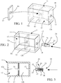
- the musical object 10 is illustrated in the figures in a parallelepipedal shape simplified as much as possible, but can of course have any other three-dimensional shape, geometric or not, fanciful or not, representing a figurine or not, this shape being defined and chosen according to of the destination of said object.
- the musical object 10 comprises in all cases a body 11, hollow and compressible, delimiting at least one closed interior cavity 12.
- the body 11 of said musical object 10 is advantageously made of an elastomeric material, such as natural or synthetic rubber, or any other technically equivalent material, that is to say having elastic properties allowing the object to resume its initial form after removal of a compressive stress. It is preferably manufactured in one piece, and comprises a continuous outer wall 14, obtained by molding as explained below. Of course and depending on the complexity of the three-dimensional shape of said object, it can be manufactured in two or more parts assembled along one or more several joint planes screwed, welded, glued, or assembled by any other known technical means, to be removable or non-removable, depending on the specifications of said object.
- the musical object 10 advantageously comprises an interior wall 15 which has the function of dividing the interior cavity 12 into two hermetic chambers 12a, 12b and of carrying a musical insert 20 so that it is placed inside said body 11, between the two chambers 12a, 12b in order to communicate only with them, without any communication with the external environment of said object.
- the interior wall 15 is preferably positioned in a middle zone of said musical object 10 to divide the interior cavity 12 into two chambers 12a, 12b of substantially equal volume.
- This embodiment is preferred but is not the only one since the two chambers could not have the same volume without affecting the operation of said musical insert 20.
- the chamber having the lower volume should have a volume. sufficient to allow sufficient air flow transfer to allow the musical insert 20 to emit sound.
- the volume of the smallest chamber is not sufficient, the air displacement will not be able to generate sound.
- the volume of these chambers 12a, 12b defines the flow of air which will pass through the musical insert 20 to create a sound each time said object is pressed.
- the total air volume of the two chambers 12a, 12b of the musical object 10 in the initial state that is to say without mechanical stress, must be determined as a function of the elasticity allowed by the material constituting the body 11 of said object and of the three-dimensional shape of said musical object 10.
- the chambers 12a, 12b must not be placed in excess pressure in the initial state of said musical object 10, because if the volume of total air is too great to saturate the chambers, there will be no possibility of air movement between the two chambers 12a, 12b and consequently no creation of sound.
- the chambers 12a, 12b must not be placed in depression in the initial state of said musical object 10, because a total volume of air that is too low will prevent any movement of air between the two chambers and any creation of sound.
- the inner wall 15 further comprises a through orifice 16 to receive and maintain in position said musical insert 20 which must ensure, during its assembly, the hermetic closure of said through orifice 16, so that the air flow F passes from a chamber to the other exclusively through the musical insert 20 to ensure optimal operation.
- This through orifice 16 is in the example shown positioned at the center of the inner wall 15 making it possible to center the musical insert 20 with respect to said body 11, without this position being compulsory.
- the position of the inner wall 15, the number of inner walls 15, the position of the musical insert 20 and the number of musical inserts 20 may vary depending on the size, shape and destination of the musical object 10.
- the inner wall 15 can be made of an identical material or at least chemically compatible with the material of said body 11. It can be manufactured separately in order to then be inserted into the manufacturing mold of said body 11 and form a single part with said body. body 11 after molding. Of course, if the body 11 of the musical object 10 is made in two or more pieces assembled along one or more parting lines, the inner wall 15 can be integrated in a parting line between two parts.
- the musical insert 20 is designed to be housed inside the internal cavity 12 of the body 11 and secured to the internal wall 15 of said object without communicating with the external environment.
- the interior cavity 12 of said body 11 is therefore closed in a sealed manner, and contains a defined and constant volume of air. This volume of air remains clean and is free from contaminants because it is never in contact with the external environment when using the musical object 10. Consequently, the musical insert 20 also remains clean. because it is confined in a hermetically sealed volume, it is therefore never polluted by contaminants or clogged with dust, and its operation is never altered.
- the As a consequence of this design is a musical object 10 offering excellent safety for the user, since the musical element 20 is never accessible, even accidentally.
- the musical insert 20 is designed to emit a sound when it is crossed by an air flow F obtained as soon as the body 11 of said musical object 10 is deformed by mechanical pressure in line with one of the chambers 12a, 12b and that the volume of air contained in this chamber 12a, 12b on one side of the inner wall 15 is expelled towards the other chamber 12b, 12a on the other side of the inner wall 15, passing through the musical insert 20 ( fig. 7 ).
- the body 11 is advantageously made of a flexible and elastic material, giving said musical object 10 great flexibility, allowing it to be easily deformed by compression and expansion generating the displacement of an air flow F of a chamber 12a, 12b to the other only through said musical insert 20, while having the ability to quickly and automatically return to its initial form as soon as it is no longer requested.
- the musical insert 20 generally makes it possible to create a sound in both directions of movement of said air flow F.
- the musical insert 20, illustrated from figure 2 can be constituted by any type of musical insert existing on the market, or can be specially designed for the present invention. It comprises a hollow musical sheath 21 forming an air duct 22 open at its two ends by an orifice 23 allowing the circulation of an air flow F passing right through the sheath.
- a musical element 30 is mounted inside the air duct 22 to be crossed by said air flow F and emit a sound when the body 11 of said musical object 10 is deformed and compressed in line with one of the chambers 12a , 12b.
- the musical element 30 and the musical sleeve 21 can form only one and the same part, or two separate parts and assembled together in a locked mounting position.
- the musical insert 20 comprises a mounting zone 25, which may or may not be central, allowing both its axial engagement in the through hole 16 of the inner wall 15, its axial locking in both directions relative to this wall and the sealing of said through orifice 16.
- This mounting zone 25 comprises for this purpose a groove 26 adapted to receive the thickness of said inner wall 15, and two lips 27 disposed on either side of said groove 26 for d 'on the one hand to lock the axial position in both directions of the musical insert 20 with respect to the inner wall 15, and on the other hand to ensure the airtightness of this assembly.
- the musical sleeve 21 is cylindrical and the mounting zone 25 is annular.
- the internal diameter of the groove 26 must be substantially equal, or even slightly greater than the diameter of the through orifice 16 to ensure a tight fit.
- the width of the groove 26 must be substantially equal or even slightly less than the thickness of the inner wall 15 in order to press the lips 27 under pressure against the two opposite faces of said wall.
- the outside diameter of the lips 27 must be greater than the diameter of the through-hole 16 to contribute to the airtightness of this assembly.
- any other equivalent technical means may be suitable.
- the cylindrical shape of the musical sleeve 21 and the annular shape of the mounting zone 25 are not limiting and may be different while ensuring the intended functions.
- the musical element 30 contained in the musical insert 20 belongs to small wind instruments. In the example illustrated, it consists of a double-entry whistle, in which the sound is created by the vibration of a reed when the air flow F flowing in the two opposite directions is compressed. one or the other chamber 12a, 12b. It is one of the known elements and will not be described in more detail. It can be made of wood, reed, metal, synthetic material such as a thermoplastic material, composite material, or a combination of at least two of these materials. Of course, any other shape and / or design of a musical element may be suitable.
- the method of manufacturing the musical object 10 comprises an operation of molding the body 11 of the object in a hollow manufacturing mold (not shown), the interior surface of which corresponds to the three-dimensional imprint of said object. It is possible to choose a rotational molding technique or rotational molding of the manufacturing mold, which makes it possible to manufacture hollow parts in a single part, without parting lines, by shaping a molten plastic material against the inner wall of a hollow manufacturing mold. It is also possible to use a two-piece injection technique with a step of bonding the two pieces on a press along a parting line. It is also possible to use a blowing technique, if the plastic material used lends itself to it.
- an elastomer such as a natural or synthetic rubber can be used as main plastics, without this example being limiting.
- the manufacturing mold is generally made in two parts, without this example being limiting, and is equipped with one or more vent, ensuring the pressure balance inside the mold.
- a dose of plastics is loaded into the mold before it is closed, defined as a function of the thickness of the wall 14 of said object to be manufactured.
- the molding phase comprises a heating step and a cooling step.
- the vent makes it possible to evacuate the gases contained in the mold to the outside of the mold during the heating step, then for the air to enter the mold during the cooling step, thus preventing the part from dying. 'be in depression.
- the interior wall 15 which was manufactured separately is added to the interior of the mold, for example between the two parts of the mold, for example.
- the musical insert 20 is introduced inside the body 11 through the vent hole 13 left in the outer wall 14 of said body 11 by the vent of the manufacturing mold. , as shown in figures 2 and 3 .
- the material forming the body 11 being flexible and elastic, the musical insert 20 can pass through the vent hole 13 which moves away from the passage of the musical sleeve 21 and the lips 27.
- the musical insert 20 is accompanied by 'inside the body 11 to fit into the inner wall 15 through the through-hole 16.
- the material forming the inner wall 15 and / or the musical sleeve 21 allows the deformation of the through-hole 16 and / or lips 27 to the passage of the musical sleeve 21 and one of the lips 27.
- a plug 17 is introduced into the vent hole 13 to close it airtight.
- this stopper 17 is shouldered and secured to the wall 14 by gluing or any other equivalent process allowing a hermetic closing of the interior cavity 12.
- any other type of stopper making it possible to fulfill the same function may be suitable. , such as an elastomeric or latex seal created by accumulation of material in the vent hole 13, an elastomeric material pad superimposed on the vent hole 13 and sealed with latex, and the like. Therefore, the term "plug" should not be interpreted in a restrictive sense.
- the musical object 10 obtained by the manufacturing method according to the invention is illustrated in the figures 5 to 7 . It constitutes an object completely airtight, containing in its interior cavity 12 a determined and constant volume of air (symbolized at the figure 5 by an equal density of points between the two chambers).
- This volume of air can be at atmospheric pressure or at a slightly higher pressure or lower than atmospheric pressure determined empirically as a function of the elasticity of the material constituting said body 11 and of the three-dimensional shape of said body 11.
- this volume of air is divided into two substantially equal parts in the two chambers 12a, 12b separated from each other in a sealed manner by the inner wall 15, through which said musical insert 20 is positioned.
- the two chambers 12a, 12b may not have the same volume.
- the balanced position of the musical object 10 is shown at figure 5 , position in which the object emits no sound.
- This balanced position corresponds to the initial state of said musical object 10, that is to say when it is not subjected to any mechanical stress.
- To create a sound it is necessary to exert a mechanical pressure on the body 11 of said musical object 10 to the right of one of the chambers 12b, represented by the arrows P at the figure 7 , which will drive part of the volume of air from this chamber 12b into the other chamber 12a, in order to create an air flow F in one direction through the musical insert 20 generating a sound.
- the volume of air expelled from one of the chambers 12b will put this chamber 12b in depression (symbolized by a density of points greater than the density of the equilibrium position of the figure 5 ) and the other chamber 12a in overpressure (symbolized by a density of points lower than the density of the equilibrium position of the figure 5 ), correspondingly increasing the volume of air and causing the expansion of the body 11 in line with this other chamber 12a represented by the arrows E.
- This unbalanced position is illustrated on figure 7 .
- a mechanical pressure (not shown) exerted on the body 11 in line with the other chamber 12a drives part of the volume of air from this chamber 12a into the other chamber 12b, creating an air flow F in the 'other direction through the musical insert 20 also generating a sound. Stopping the stresses by compression of the musical object 10 results in an automatic rebalancing of the pressures between the two chambers 12a, 12b via the musical insert 20 which may or may not generate a sound depending on its sensitivity.
- the musical object 10 automatically returns to its balanced position or to its initial state ( fig. 5 ) and no longer emits sound.
- this musical object 10 can emit sounds without being in communication with the external environment, by a simple transfer of air between two hermetically sealed chambers 12a, 12b via a musical insert 20.
- this musical object 10 is said "clean" given that its internal volume and its musical insert 20 are protected from the user and the external environment by its hermetically sealed body 11, avoiding any risk of contamination. It can also be easily washed, cleaned and disinfected to again avoid any risk of contamination by touch.
- This musical object 10 can be used in all types of applications, both in the field of rescue as a sound alert, in the field of sport as a means of arbitration, in the field of leisure as a musical instrument, in the field of entertainment such as squeaker or whistle toy for children and pets etc. Its particular design makes this musical object 10 a completely secure device for the user since the musical insert 20 is not accessible, even accidentally.
Landscapes
- Engineering & Computer Science (AREA)
- Acoustics & Sound (AREA)
- Multimedia (AREA)
- Physics & Mathematics (AREA)
- Life Sciences & Earth Sciences (AREA)
- Environmental Sciences (AREA)
- Health & Medical Sciences (AREA)
- Physical Education & Sports Medicine (AREA)
- Animal Behavior & Ethology (AREA)
- Zoology (AREA)
- Animal Husbandry (AREA)
- Biodiversity & Conservation Biology (AREA)
- General Health & Medical Sciences (AREA)
- Toys (AREA)
- Electrophonic Musical Instruments (AREA)
- Stringed Musical Instruments (AREA)
Claims (11)
- Verfahren zur Herstellung eines Musikinstrumentes (10), dieses Musikinstrument umfasst einen hohlen und komprimierbaren Körper (11), ausgeführt aus einem flexiblen und elastischen Material, der einen Innenraum (12) umschließt, eine Innenwand (15), angeordnet im Inneren dieses Körpers (11) zur Unterteilung dieses Innenraums (12) in zwei Kammern (12a, 12b), und einen musikalischen Einsatz (20), montiert durch diese Innenwand (15) hindurch, damit diese Kammern (12a, 12b) kommunizieren und dazu vorgesehen, einen Ton abzugeben, wenn ein Luftstrom (F) hindurchfließt, dieser Luftstrom wird dabei durch einen mechanischen Druck erzeugt, der auf diesen Körper (11) über eine dieser Kammern ausgeübt wird, ein Verfahren, bei dem der Körper (11) dieses Musikinstrumentes (10) nach einer Gießtechnik aus Elastomermaterial hergestellt wird, das in einer hohlen Herstellungsform, mit einer Öffnung hergestellt wird, der Innenraum dieser Form entspricht dem dreidimensionalen Abdruck dieses Körpers (11), dadurch gekennzeichnet, dass die erwähnte Innenwand (15) getrennt hergestellt wird, sie ist versehen mit einer durchführenden Öffnung (16), vorgesehen zur Aufnahme und zum in Position Halten des erwähnten musikalischen Einsatzes (20), dadurch dass vor dem Schritt des Gießens dieses Körpers (11), in diese Gießform diese Innenwand (15) eingesetzt wird, so dass ihr Umfang von diesem Körper (11) im Schritt des Gießens überformt wird und dass nach dem Vorgang des Gießens dieses Körpers (11), der erwähnte musikalische Einsatz (20) in diesen Körper (11) durch das Öffnungsloch (13) eingeführt wird, das in der Außenwand (14) dieses Körpers (11) ausgespart wurde, durch die Öffnung dieser Herstellungsform, um ihn in die Innenwand (15) durch die durchführende Öffnung (16) hindurch einzusetzen und gleichzeitig diese durchführende Öffnung hermetisch zu verschließen, und dadurch dass, nach der Montage des musikalischen Einsatzes (20) in diesem Körper (11), das erwähnte Öffnungsloch (13) mit einem Stopfen (17) geschlossen wird, so dass es dicht verschlossen ist und der erwähnte Innenraum (12) hermetisch geschlossen ist, so dass der erwähnte musikalische Einsatz (20) im Inneren dieses Körpers (11) angeordnet ist zwischen den beiden Kammern (12a, 12b), um so nur mit diesen zu kommunizieren, ohne irgendeine Kommunikation mit der äußeren Umgebung dieses Musikinstrumentes (10).
- Herstellungsverfahren nach Anspruch 1, dadurch gekennzeichnet, dass der erwähnte Innenraum (12) mit einem bestimmten und konstanten Luftvolumen gefüllt wird, unter Berücksichtigung der Elastizität des Materials, das diesen Körper (11) bildet und der dreidimensionalen Form dieses Körpers (11), um eine Verlagerung der Luft zwischen den beiden Kammern (12a, 12b) zu erlauben, wenn ein mechanischer Druck auf diesen Körper (11) über eine dieser Kammern ausgeübt wird und so die Schaffung eines Tons bei jeder mechanischen Beanspruchung dieses Objektes zu erlauben.
- Herstellungsverfahren nach Anspruch 1, dadurch gekennzeichnet, dass für die Innenwand (15) und den Körper (11) dieses Musikinstrumentes (10) ein ähnliches elastomeres Material verwendet wird, identisch oder kompatibel, das eine Fusion zwischen den beiden Materialien beim Gießvorgang erlaubt.
- Herstellungsverfahren nach Anspruch 3, dadurch gekennzeichnet, dass dieses elastomere Material ausgewählt wird aus natürlichen Kautschuksorten, synthetischen Kautschuksorten und thermoplastischen Elastomeren.
- Herstellungsverfahren nach Anspruch 1, dadurch gekennzeichnet, dass diese Gießtechnik eine Rotationsformung ist.
- Herstellungsverfahren nach Anspruch 1, dadurch gekennzeichnet, dass an dem erwähnten musikalischen Einsatz (20) eine Montagezone (25) vorgesehen ist, die zu der durchführenden Öffnung (16), die in der erwähnten Innenwand (15) vorgesehen ist komplementär und so ausgelegt ist, dass sie die erwähnte durchführende Öffnung (16) hermetisch verschließt.
- Herstellungsverfahren nach Anspruch 6, dadurch gekennzeichnet, dass diese Montagezone (25) in Form einer Nut (26) ausgeführt wird, ausgelegt zur Aufnahme der durchführenden Öffnung (16), und der beiden Lippen (27) die beiderseits dieser Nut (26) angeordnet sind und dazu dienen, sich gegen die beiden gegenüberliegenden Seiten dieser Innenwand (15) zu pressen und diesen musikalischen Einsatzes (20) bezogen auf diese Innenwand (15) in der Montageposition zu halten und diese durchführende Öffnung (16) hermetisch zu verschließen.
- Musikinstrument (10), erhalten durch das Herstellungsverfahren nach irgendeinem der vorangehenden Ansprüche, dieses Musikinstrument umfasst einen hohlen und komprimierbaren Körper (11), ausgeführt aus einem flexiblen und elastischen Material, der einen Innenraum (12) umschließt, eine Innenwand (15), angeordnet im Inneren dieses Körpers (11), zur Unterteilung dieses Innenraums (12) in zwei Kammern (12a, 12b), und einen musikalischen Einsatz (20), montiert durch diese Innenwand (15) hindurch, damit diese Kammern (12a, 12b) kommunizieren können und dazu vorgesehen, einen Ton abzugeben, wenn ein Luftstrom (F) hindurchfließt, dieser Luftstrom wird durch einen mechanischen Druck erzeugt, der auf diesen Körper (11) über eine dieser Kammern ausgeübt wird dadurch gekennzeichnet, dass der Umfang der erwähnten Innenwand (15) von diesem Körper (11) überformt wird und eine durchführende Öffnung (16) enthält, vorgesehen zur Aufnahme des erwähnten musikalischen Einsatzes (20) und ihn in Position zu halten, dadurch, dass der erwähnte musikalische Einsatz (20) dazu ausgelegt ist, diese durchführende Öffnung (16) hermetisch zu verschließen und dass der erwähnte Körper (11) ein Öffnungsloch (13) enthält, das hermetisch durch einen Stopfen (17) verschlossen ist, so dass dieser musikalische Einsatz (20) im Inneren dieses Körpers (11), zwischen den beiden Kammern (12a, 12b) angeordnet ist, um nur mit diesen zu kommunizieren, ohne irgendeine Kommunikation mit der Außenumgebung dieses Musikinstrumentes (10).
- Musikinstrument nach Anspruch 8, dadurch gekennzeichnet, dass der erwähnte Innenraum (12) mit einem bestimmten und konstanten Luftvolumen gefüllt wird, unter Berücksichtigung der Elastizität des Materials, das diesen Körper (11) bildet und der dreidimensionalen Form dieses Körpers (11), um eine Verlagerung der Luft zwischen den beiden Kammern (12a, 12b) zu erlauben, wenn ein mechanischer Druck auf diesen Körper (11) über eine dieser Kammern ausgeübt wird und so die Schaffung eines Tons bei jeder mechanischen Beanspruchung dieses Objektes zu erlauben.
- Musikinstrument nach Anspruch 8, dadurch gekennzeichnet, dass der erwähnte musikalische Einsatz (20) eine Montagezone (25) enthält, die zu der durchführenden Öffnung (16), die in der erwähnten Innenwand (15) vorgesehen ist komplementär und so ausgelegt ist, dass sie die erwähnte durchführende Öffnung hermetisch verschließt.
- Musikinstrument nach Anspruch 10, dadurch gekennzeichnet, dass diese Montagezone (25) in Form einer Nut (26) ausgeführt wird, ausgelegt zur Aufnahme der durchführenden Öffnung (16) und der beiden Lippen (27), die beiderseits dieser Nut (26) angeordnet sind und dazu dienen, sich gegen die beiden gegenüberliegenden Seiten dieser Innenwand (15) zu pressen und diesen musikalischen Einsatzes (20) bezogen auf diese Innenwand (15) in der Montageposition zu halten und diese durchführende Öffnung (16) hermetisch zu verschließen.
Applications Claiming Priority (2)
| Application Number | Priority Date | Filing Date | Title |
|---|---|---|---|
| FR1761581A FR3074603B1 (fr) | 2017-12-04 | 2017-12-04 | Procede de fabrication d'un objet musical et objet musical obtenu |
| PCT/EP2018/083371 WO2019110520A1 (fr) | 2017-12-04 | 2018-12-03 | Procede de fabrication d'un objet musical et objet musical obtenu |
Publications (2)
| Publication Number | Publication Date |
|---|---|
| EP3703836A1 EP3703836A1 (de) | 2020-09-09 |
| EP3703836B1 true EP3703836B1 (de) | 2021-11-17 |
Family
ID=61224074
Family Applications (1)
| Application Number | Title | Priority Date | Filing Date |
|---|---|---|---|
| EP18811264.3A Active EP3703836B1 (de) | 2017-12-04 | 2018-12-03 | Verfahren zur herstellung eines musikinstruments und so erhaltenes musikinstrument |
Country Status (8)
| Country | Link |
|---|---|
| US (1) | US11676566B2 (de) |
| EP (1) | EP3703836B1 (de) |
| CN (1) | CN111432903B (de) |
| DK (1) | DK3703836T3 (de) |
| ES (1) | ES2899861T3 (de) |
| FR (1) | FR3074603B1 (de) |
| MA (1) | MA50521B1 (de) |
| WO (1) | WO2019110520A1 (de) |
Families Citing this family (1)
| Publication number | Priority date | Publication date | Assignee | Title |
|---|---|---|---|---|
| CN111011244A (zh) * | 2019-11-18 | 2020-04-17 | 常熟市双荣宠物用品有限公司 | 一种组合型宠物玩具 |
Family Cites Families (27)
| Publication number | Priority date | Publication date | Assignee | Title |
|---|---|---|---|---|
| US1461193A (en) * | 1922-02-10 | 1923-07-10 | Larsen Hans | Pneumatic toy |
| FR587841A (fr) * | 1924-10-22 | 1925-04-24 | Procédé de fixation intérieure de sifflets ou autres appareils sonores des jouetset autres objets creux en caoutchouc ou autre matière élastique | |
| NL51000C (de) * | 1937-12-10 | |||
| US2712201A (en) * | 1952-09-09 | 1955-07-05 | Wintriss Inc | Whistle for pneumatic toys |
| US2817116A (en) * | 1955-04-08 | 1957-12-24 | Theodore A Miller | Mold for making a sound producing article |
| US4380134A (en) * | 1976-09-28 | 1983-04-19 | Taluba Anthony P | Molded squeeze toy including whistle |
| AU714503B2 (en) * | 1998-04-02 | 2000-01-06 | Wayne Turrong Peckham | A method of making a musical instrument |
| FR2793152B1 (fr) | 1999-05-07 | 2001-07-20 | Michel Flageollet | Sifflet manuel |
| US8322308B2 (en) | 2000-03-16 | 2012-12-04 | Jon K Curry | Animal toy with adjustable squeaker |
| US9345234B2 (en) * | 2000-03-16 | 2016-05-24 | Jon K. Curry | Fabric covered elastic polymer animal toy with soft pliable fabric head |
| US6935274B1 (en) * | 2002-06-25 | 2005-08-30 | Steven M. Rothschild | Pet toy |
| US20120103274A1 (en) | 2010-10-28 | 2012-05-03 | Curry Jon K | Animal toy with induction charging system |
| US7264533B2 (en) * | 2004-06-18 | 2007-09-04 | T. K. Wong & Associates Ltd. | Bubble-squeezing toy |
| US7066779B2 (en) * | 2004-07-13 | 2006-06-27 | Jw Pet Company | Mounting arrangement for squeakers |
| US8235762B2 (en) * | 2005-12-20 | 2012-08-07 | J.W. Pet Company, Inc. | Mounting arrangement for squeaker |
| US7833079B2 (en) * | 2004-07-13 | 2010-11-16 | J.W. Pet Company, Inc. | Noise producing toy structure |
| CN201006306Y (zh) * | 2007-03-19 | 2008-01-16 | 台州中泰海洋广场有限公司 | 一种发声玩具棒 |
| US8468977B2 (en) | 2007-08-07 | 2013-06-25 | The Kong Company, Llc | Pet toy with noise making instrument |
| WO2010068909A2 (en) * | 2008-12-12 | 2010-06-17 | Michael Steven Brockman | Unified octave/register key and vent for musical wind instruments |
| JP5866665B2 (ja) * | 2011-09-27 | 2016-02-17 | 三共理研株式会社 | 笛玩具 |
| US20130097901A1 (en) * | 2011-10-05 | 2013-04-25 | John Scott Cooper | Play toys and techniques for fabricating play toys |
| US9370167B2 (en) * | 2012-10-18 | 2016-06-21 | Otomik Products, Inc. | Pet toy with squeaker mechanism |
| CN204217652U (zh) * | 2014-09-25 | 2015-03-25 | 上海悦远贸易有限公司 | 一种宠物玩具 |
| CN204582541U (zh) * | 2015-01-15 | 2015-08-26 | 宁波市阳普生进出口有限公司 | 一种搪胶玩具 |
| WO2017045166A1 (zh) | 2015-09-16 | 2017-03-23 | 尚平 | 一种防水的电子哨子 |
| US10681899B1 (en) * | 2016-06-15 | 2020-06-16 | Gramercy Products, Inc. | Squeaker assembly for child and pet toys |
| FR3071171B1 (fr) * | 2017-09-15 | 2019-09-13 | Sophie La Girafe | Insert musical, procede de fabrication d'un jouet musical pourvu dudit insert et jouet musical obtenu par ledit procede |
-
2017
- 2017-12-04 FR FR1761581A patent/FR3074603B1/fr not_active Expired - Fee Related
-
2018
- 2018-12-03 WO PCT/EP2018/083371 patent/WO2019110520A1/fr not_active Ceased
- 2018-12-03 DK DK18811264.3T patent/DK3703836T3/da active
- 2018-12-03 US US16/763,093 patent/US11676566B2/en active Active
- 2018-12-03 MA MA50521A patent/MA50521B1/fr unknown
- 2018-12-03 ES ES18811264T patent/ES2899861T3/es active Active
- 2018-12-03 CN CN201880078045.7A patent/CN111432903B/zh active Active
- 2018-12-03 EP EP18811264.3A patent/EP3703836B1/de active Active
Also Published As
| Publication number | Publication date |
|---|---|
| ES2899861T3 (es) | 2022-03-15 |
| WO2019110520A1 (fr) | 2019-06-13 |
| MA50521A (fr) | 2020-09-09 |
| DK3703836T3 (da) | 2022-01-03 |
| FR3074603A1 (fr) | 2019-06-07 |
| CN111432903B (zh) | 2022-02-11 |
| FR3074603B1 (fr) | 2021-03-19 |
| MA50521B1 (fr) | 2021-12-31 |
| EP3703836A1 (de) | 2020-09-09 |
| CN111432903A (zh) | 2020-07-17 |
| US20200365130A1 (en) | 2020-11-19 |
| US11676566B2 (en) | 2023-06-13 |
Similar Documents
| Publication | Publication Date | Title |
|---|---|---|
| FR2972337A1 (fr) | Contenant, notamment pot de produit cosmetique, et procede de fabrication associe | |
| FR2526757A1 (fr) | Recipient en resine synthetique et procede pour son formage | |
| EP3703836B1 (de) | Verfahren zur herstellung eines musikinstruments und so erhaltenes musikinstrument | |
| EP0764590B1 (de) | Aufbewahrungs- und Spendevorrichtung | |
| FR3071171B1 (fr) | Insert musical, procede de fabrication d'un jouet musical pourvu dudit insert et jouet musical obtenu par ledit procede | |
| EP0940150B1 (de) | Vorrichtung zum Absaugen von Nasenschleim | |
| EP3388218B1 (de) | Anspritzen eines optischen elements auf einem thermoplastikrahmen | |
| EP0825128A2 (de) | Element zur Befestigung einer Abgabevorrichtung an einem Behälterhals | |
| WO1996008220A1 (fr) | Boitier de conditionnement pour preservatif | |
| WO2003084835A1 (fr) | Charniere et bouchon comportant une telle charniere | |
| FR2756347A1 (fr) | Vanne a boisseau cylindrique | |
| FR2973781A1 (fr) | Bouchon a obturateur coulissant presentant plusieurs trous de distribution | |
| EP1094372B1 (de) | Betätigungsknopf | |
| EP0485289A1 (de) | Verpackung für gefährliche Stoffe, zerbrechliche Behälter o.d. | |
| CA2778296A1 (fr) | Tetine hygienique | |
| FR2972831A1 (fr) | Télécommande pour automatisation et procédé de fabrication | |
| CA1315311C (fr) | Valve monobloc pour enceinte fermee, son procede de fabrication et moyens pour la mise en oeuvre de ce procede | |
| CA2519698A1 (fr) | Distributeur de fluide | |
| EP1234656A1 (de) | Rad, insbesondere für leichte Fahrzeuge, und Verfahren zu dessen Herstellung | |
| WO2004002596A1 (fr) | Structure constituee d'une enveloppe souple mise en forme par un rembourrage interne, munie de moyens d'agrementation en produit odoriferant | |
| FR2955765A1 (fr) | Biberon d'allaitement a corps perfectionne | |
| HK40027111B (zh) | 用於生产乐器的方法和通过该方法获得的乐器 | |
| FR2587225A1 (fr) | Ballon parfume et valve | |
| HK40027111A (en) | Method for producing musical instrument and musical instrument obtained by the method | |
| FR2866832A1 (fr) | Diffuseur de substances volatiles pour vehicule automobile |
Legal Events
| Date | Code | Title | Description |
|---|---|---|---|
| STAA | Information on the status of an ep patent application or granted ep patent |
Free format text: STATUS: UNKNOWN |
|
| STAA | Information on the status of an ep patent application or granted ep patent |
Free format text: STATUS: THE INTERNATIONAL PUBLICATION HAS BEEN MADE |
|
| PUAI | Public reference made under article 153(3) epc to a published international application that has entered the european phase |
Free format text: ORIGINAL CODE: 0009012 |
|
| STAA | Information on the status of an ep patent application or granted ep patent |
Free format text: STATUS: REQUEST FOR EXAMINATION WAS MADE |
|
| 17P | Request for examination filed |
Effective date: 20200603 |
|
| AK | Designated contracting states |
Kind code of ref document: A1 Designated state(s): AL AT BE BG CH CY CZ DE DK EE ES FI FR GB GR HR HU IE IS IT LI LT LU LV MC MK MT NL NO PL PT RO RS SE SI SK SM TR |
|
| AX | Request for extension of the european patent |
Extension state: BA ME |
|
| DAX | Request for extension of the european patent (deleted) | ||
| RAV | Requested validation state of the european patent: fee paid |
Extension state: MA Effective date: 20200603 |
|
| REG | Reference to a national code |
Ref country code: DE Ref legal event code: R079 Ref document number: 602018026933 Country of ref document: DE Free format text: PREVIOUS MAIN CLASS: A63H0003280000 Ipc: G10K0015040000 |
|
| GRAP | Despatch of communication of intention to grant a patent |
Free format text: ORIGINAL CODE: EPIDOSNIGR1 |
|
| STAA | Information on the status of an ep patent application or granted ep patent |
Free format text: STATUS: GRANT OF PATENT IS INTENDED |
|
| RIC1 | Information provided on ipc code assigned before grant |
Ipc: G10K 15/04 20060101AFI20210622BHEP Ipc: A63H 5/00 20060101ALI20210622BHEP Ipc: A01K 15/02 20060101ALI20210622BHEP |
|
| INTG | Intention to grant announced |
Effective date: 20210715 |
|
| GRAS | Grant fee paid |
Free format text: ORIGINAL CODE: EPIDOSNIGR3 |
|
| GRAA | (expected) grant |
Free format text: ORIGINAL CODE: 0009210 |
|
| STAA | Information on the status of an ep patent application or granted ep patent |
Free format text: STATUS: THE PATENT HAS BEEN GRANTED |
|
| AK | Designated contracting states |
Kind code of ref document: B1 Designated state(s): AL AT BE BG CH CY CZ DE DK EE ES FI FR GB GR HR HU IE IS IT LI LT LU LV MC MK MT NL NO PL PT RO RS SE SI SK SM TR |
|
| REG | Reference to a national code |
Ref country code: GB Ref legal event code: FG4D Free format text: NOT ENGLISH |
|
| REG | Reference to a national code |
Ref country code: IE Ref legal event code: FG4D Free format text: LANGUAGE OF EP DOCUMENT: FRENCH |
|
| REG | Reference to a national code |
Ref country code: DE Ref legal event code: R096 Ref document number: 602018026933 Country of ref document: DE |
|
| REG | Reference to a national code |
Ref country code: AT Ref legal event code: REF Ref document number: 1448737 Country of ref document: AT Kind code of ref document: T Effective date: 20211215 |
|
| REG | Reference to a national code |
Ref country code: NL Ref legal event code: FP |
|
| REG | Reference to a national code |
Ref country code: MA Ref legal event code: VAGR Ref document number: 50521 Country of ref document: MA Kind code of ref document: B1 |
|
| REG | Reference to a national code |
Ref country code: DK Ref legal event code: T3 Effective date: 20211221 |
|
| REG | Reference to a national code |
Ref country code: LT Ref legal event code: MG9D |
|
| REG | Reference to a national code |
Ref country code: ES Ref legal event code: FG2A Ref document number: 2899861 Country of ref document: ES Kind code of ref document: T3 Effective date: 20220315 |
|
| REG | Reference to a national code |
Ref country code: AT Ref legal event code: MK05 Ref document number: 1448737 Country of ref document: AT Kind code of ref document: T Effective date: 20211117 |
|
| PG25 | Lapsed in a contracting state [announced via postgrant information from national office to epo] |
Ref country code: RS Free format text: LAPSE BECAUSE OF FAILURE TO SUBMIT A TRANSLATION OF THE DESCRIPTION OR TO PAY THE FEE WITHIN THE PRESCRIBED TIME-LIMIT Effective date: 20211117 Ref country code: LT Free format text: LAPSE BECAUSE OF FAILURE TO SUBMIT A TRANSLATION OF THE DESCRIPTION OR TO PAY THE FEE WITHIN THE PRESCRIBED TIME-LIMIT Effective date: 20211117 Ref country code: FI Free format text: LAPSE BECAUSE OF FAILURE TO SUBMIT A TRANSLATION OF THE DESCRIPTION OR TO PAY THE FEE WITHIN THE PRESCRIBED TIME-LIMIT Effective date: 20211117 Ref country code: BG Free format text: LAPSE BECAUSE OF FAILURE TO SUBMIT A TRANSLATION OF THE DESCRIPTION OR TO PAY THE FEE WITHIN THE PRESCRIBED TIME-LIMIT Effective date: 20220217 Ref country code: AT Free format text: LAPSE BECAUSE OF FAILURE TO SUBMIT A TRANSLATION OF THE DESCRIPTION OR TO PAY THE FEE WITHIN THE PRESCRIBED TIME-LIMIT Effective date: 20211117 |
|
| PG25 | Lapsed in a contracting state [announced via postgrant information from national office to epo] |
Ref country code: IS Free format text: LAPSE BECAUSE OF FAILURE TO SUBMIT A TRANSLATION OF THE DESCRIPTION OR TO PAY THE FEE WITHIN THE PRESCRIBED TIME-LIMIT Effective date: 20220317 Ref country code: SE Free format text: LAPSE BECAUSE OF FAILURE TO SUBMIT A TRANSLATION OF THE DESCRIPTION OR TO PAY THE FEE WITHIN THE PRESCRIBED TIME-LIMIT Effective date: 20211117 Ref country code: PT Free format text: LAPSE BECAUSE OF FAILURE TO SUBMIT A TRANSLATION OF THE DESCRIPTION OR TO PAY THE FEE WITHIN THE PRESCRIBED TIME-LIMIT Effective date: 20220317 Ref country code: PL Free format text: LAPSE BECAUSE OF FAILURE TO SUBMIT A TRANSLATION OF THE DESCRIPTION OR TO PAY THE FEE WITHIN THE PRESCRIBED TIME-LIMIT Effective date: 20211117 Ref country code: NO Free format text: LAPSE BECAUSE OF FAILURE TO SUBMIT A TRANSLATION OF THE DESCRIPTION OR TO PAY THE FEE WITHIN THE PRESCRIBED TIME-LIMIT Effective date: 20220217 Ref country code: LV Free format text: LAPSE BECAUSE OF FAILURE TO SUBMIT A TRANSLATION OF THE DESCRIPTION OR TO PAY THE FEE WITHIN THE PRESCRIBED TIME-LIMIT Effective date: 20211117 Ref country code: HR Free format text: LAPSE BECAUSE OF FAILURE TO SUBMIT A TRANSLATION OF THE DESCRIPTION OR TO PAY THE FEE WITHIN THE PRESCRIBED TIME-LIMIT Effective date: 20211117 Ref country code: GR Free format text: LAPSE BECAUSE OF FAILURE TO SUBMIT A TRANSLATION OF THE DESCRIPTION OR TO PAY THE FEE WITHIN THE PRESCRIBED TIME-LIMIT Effective date: 20220218 |
|
| PG25 | Lapsed in a contracting state [announced via postgrant information from national office to epo] |
Ref country code: SM Free format text: LAPSE BECAUSE OF FAILURE TO SUBMIT A TRANSLATION OF THE DESCRIPTION OR TO PAY THE FEE WITHIN THE PRESCRIBED TIME-LIMIT Effective date: 20211117 Ref country code: SK Free format text: LAPSE BECAUSE OF FAILURE TO SUBMIT A TRANSLATION OF THE DESCRIPTION OR TO PAY THE FEE WITHIN THE PRESCRIBED TIME-LIMIT Effective date: 20211117 Ref country code: RO Free format text: LAPSE BECAUSE OF FAILURE TO SUBMIT A TRANSLATION OF THE DESCRIPTION OR TO PAY THE FEE WITHIN THE PRESCRIBED TIME-LIMIT Effective date: 20211117 Ref country code: EE Free format text: LAPSE BECAUSE OF FAILURE TO SUBMIT A TRANSLATION OF THE DESCRIPTION OR TO PAY THE FEE WITHIN THE PRESCRIBED TIME-LIMIT Effective date: 20211117 Ref country code: CZ Free format text: LAPSE BECAUSE OF FAILURE TO SUBMIT A TRANSLATION OF THE DESCRIPTION OR TO PAY THE FEE WITHIN THE PRESCRIBED TIME-LIMIT Effective date: 20211117 |
|
| REG | Reference to a national code |
Ref country code: DE Ref legal event code: R097 Ref document number: 602018026933 Country of ref document: DE |
|
| PG25 | Lapsed in a contracting state [announced via postgrant information from national office to epo] |
Ref country code: MC Free format text: LAPSE BECAUSE OF FAILURE TO SUBMIT A TRANSLATION OF THE DESCRIPTION OR TO PAY THE FEE WITHIN THE PRESCRIBED TIME-LIMIT Effective date: 20211117 |
|
| PLBE | No opposition filed within time limit |
Free format text: ORIGINAL CODE: 0009261 |
|
| STAA | Information on the status of an ep patent application or granted ep patent |
Free format text: STATUS: NO OPPOSITION FILED WITHIN TIME LIMIT |
|
| 26N | No opposition filed |
Effective date: 20220818 |
|
| PG25 | Lapsed in a contracting state [announced via postgrant information from national office to epo] |
Ref country code: LU Free format text: LAPSE BECAUSE OF NON-PAYMENT OF DUE FEES Effective date: 20211203 Ref country code: IE Free format text: LAPSE BECAUSE OF NON-PAYMENT OF DUE FEES Effective date: 20211203 Ref country code: AL Free format text: LAPSE BECAUSE OF FAILURE TO SUBMIT A TRANSLATION OF THE DESCRIPTION OR TO PAY THE FEE WITHIN THE PRESCRIBED TIME-LIMIT Effective date: 20211117 |
|
| PG25 | Lapsed in a contracting state [announced via postgrant information from national office to epo] |
Ref country code: SI Free format text: LAPSE BECAUSE OF FAILURE TO SUBMIT A TRANSLATION OF THE DESCRIPTION OR TO PAY THE FEE WITHIN THE PRESCRIBED TIME-LIMIT Effective date: 20211117 |
|
| PG25 | Lapsed in a contracting state [announced via postgrant information from national office to epo] |
Ref country code: IT Free format text: LAPSE BECAUSE OF FAILURE TO SUBMIT A TRANSLATION OF THE DESCRIPTION OR TO PAY THE FEE WITHIN THE PRESCRIBED TIME-LIMIT Effective date: 20211117 |
|
| PG25 | Lapsed in a contracting state [announced via postgrant information from national office to epo] |
Ref country code: CY Free format text: LAPSE BECAUSE OF FAILURE TO SUBMIT A TRANSLATION OF THE DESCRIPTION OR TO PAY THE FEE WITHIN THE PRESCRIBED TIME-LIMIT Effective date: 20211117 |
|
| P01 | Opt-out of the competence of the unified patent court (upc) registered |
Effective date: 20230527 |
|
| PG25 | Lapsed in a contracting state [announced via postgrant information from national office to epo] |
Ref country code: HU Free format text: LAPSE BECAUSE OF FAILURE TO SUBMIT A TRANSLATION OF THE DESCRIPTION OR TO PAY THE FEE WITHIN THE PRESCRIBED TIME-LIMIT; INVALID AB INITIO Effective date: 20181203 |
|
| PG25 | Lapsed in a contracting state [announced via postgrant information from national office to epo] |
Ref country code: MK Free format text: LAPSE BECAUSE OF FAILURE TO SUBMIT A TRANSLATION OF THE DESCRIPTION OR TO PAY THE FEE WITHIN THE PRESCRIBED TIME-LIMIT Effective date: 20211117 |
|
| PG25 | Lapsed in a contracting state [announced via postgrant information from national office to epo] |
Ref country code: MT Free format text: LAPSE BECAUSE OF FAILURE TO SUBMIT A TRANSLATION OF THE DESCRIPTION OR TO PAY THE FEE WITHIN THE PRESCRIBED TIME-LIMIT Effective date: 20211117 |
|
| PGFP | Annual fee paid to national office [announced via postgrant information from national office to epo] |
Ref country code: DE Payment date: 20241211 Year of fee payment: 7 |
|
| PGFP | Annual fee paid to national office [announced via postgrant information from national office to epo] |
Ref country code: ES Payment date: 20250107 Year of fee payment: 7 |
|
| PGFP | Annual fee paid to national office [announced via postgrant information from national office to epo] |
Ref country code: CH Payment date: 20250101 Year of fee payment: 7 |
|
| VSFP | Annual fee paid to validation state [announced via postgrant information from national office to epo] |
Ref country code: MA Payment date: 20231130 Year of fee payment: 6 |
|
| VSFP | Annual fee paid to validation state [announced via postgrant information from national office to epo] |
Ref country code: MA Payment date: 20221201 Year of fee payment: 5 Ref country code: MA Payment date: 20211220 Year of fee payment: 4 |
|
| VSFP | Annual fee paid to validation state [announced via postgrant information from national office to epo] |
Ref country code: MA Payment date: 20241203 Year of fee payment: 7 |
|
| PGFP | Annual fee paid to national office [announced via postgrant information from national office to epo] |
Ref country code: NL Payment date: 20251127 Year of fee payment: 8 |
|
| REG | Reference to a national code |
Ref country code: CH Ref legal event code: U11 Free format text: ST27 STATUS EVENT CODE: U-0-0-U10-U11 (AS PROVIDED BY THE NATIONAL OFFICE) Effective date: 20260101 |
|
| PGFP | Annual fee paid to national office [announced via postgrant information from national office to epo] |
Ref country code: GB Payment date: 20251229 Year of fee payment: 8 |
|
| PGFP | Annual fee paid to national office [announced via postgrant information from national office to epo] |
Ref country code: DK Payment date: 20251127 Year of fee payment: 8 |
|
| PGFP | Annual fee paid to national office [announced via postgrant information from national office to epo] |
Ref country code: FR Payment date: 20251222 Year of fee payment: 8 |
|
| PGFP | Annual fee paid to national office [announced via postgrant information from national office to epo] |
Ref country code: BE Payment date: 20251226 Year of fee payment: 8 Ref country code: TR Payment date: 20251126 Year of fee payment: 8 |