EP3703836B1 - Method for producing a musical instrument and musical instrument obtained thereby - Google Patents
Method for producing a musical instrument and musical instrument obtained thereby Download PDFInfo
- Publication number
- EP3703836B1 EP3703836B1 EP18811264.3A EP18811264A EP3703836B1 EP 3703836 B1 EP3703836 B1 EP 3703836B1 EP 18811264 A EP18811264 A EP 18811264A EP 3703836 B1 EP3703836 B1 EP 3703836B1
- Authority
- EP
- European Patent Office
- Prior art keywords
- musical
- orifice
- chambers
- insert
- internal wall
- Prior art date
- Legal status (The legal status is an assumption and is not a legal conclusion. Google has not performed a legal analysis and makes no representation as to the accuracy of the status listed.)
- Active
Links
- 238000004519 manufacturing process Methods 0.000 title claims description 38
- 239000000463 material Substances 0.000 claims description 26
- 238000000465 moulding Methods 0.000 claims description 23
- 238000000034 method Methods 0.000 claims description 13
- 238000004891 communication Methods 0.000 claims description 9
- 239000013013 elastic material Substances 0.000 claims description 5
- 229920003052 natural elastomer Polymers 0.000 claims description 5
- 229920001194 natural rubber Polymers 0.000 claims description 5
- 229920003051 synthetic elastomer Polymers 0.000 claims description 5
- 239000005061 synthetic rubber Substances 0.000 claims description 5
- 230000000295 complement effect Effects 0.000 claims description 4
- 229920001971 elastomer Polymers 0.000 claims description 4
- 239000000806 elastomer Substances 0.000 claims description 4
- 238000001175 rotational moulding Methods 0.000 claims description 4
- 244000043261 Hevea brasiliensis Species 0.000 claims description 2
- 229920002725 thermoplastic elastomer Polymers 0.000 claims 1
- 239000003570 air Substances 0.000 description 42
- 208000031968 Cadaver Diseases 0.000 description 6
- 238000011109 contamination Methods 0.000 description 6
- 239000013536 elastomeric material Substances 0.000 description 6
- 239000004033 plastic Substances 0.000 description 5
- 229920003023 plastic Polymers 0.000 description 5
- 239000000356 contaminant Substances 0.000 description 4
- 241001465754 Metazoa Species 0.000 description 3
- 230000006835 compression Effects 0.000 description 3
- 238000007906 compression Methods 0.000 description 3
- 238000013461 design Methods 0.000 description 3
- 239000004816 latex Substances 0.000 description 3
- 229920000126 latex Polymers 0.000 description 3
- 239000000243 solution Substances 0.000 description 3
- 241001441705 Mochokidae Species 0.000 description 2
- 235000014676 Phragmites communis Nutrition 0.000 description 2
- 238000004026 adhesive bonding Methods 0.000 description 2
- 238000004140 cleaning Methods 0.000 description 2
- 238000001816 cooling Methods 0.000 description 2
- 238000012864 cross contamination Methods 0.000 description 2
- 238000006073 displacement reaction Methods 0.000 description 2
- 230000004927 fusion Effects 0.000 description 2
- 239000007789 gas Substances 0.000 description 2
- 238000010438 heat treatment Methods 0.000 description 2
- 238000002347 injection Methods 0.000 description 2
- 239000007924 injection Substances 0.000 description 2
- 238000003780 insertion Methods 0.000 description 2
- 230000037431 insertion Effects 0.000 description 2
- 230000008569 process Effects 0.000 description 2
- 238000012546 transfer Methods 0.000 description 2
- 238000009825 accumulation Methods 0.000 description 1
- 239000012080 ambient air Substances 0.000 description 1
- 238000007664 blowing Methods 0.000 description 1
- 239000002131 composite material Substances 0.000 description 1
- 238000001035 drying Methods 0.000 description 1
- 239000000428 dust Substances 0.000 description 1
- 230000036541 health Effects 0.000 description 1
- 238000007654 immersion Methods 0.000 description 1
- 238000009434 installation Methods 0.000 description 1
- 230000035800 maturation Effects 0.000 description 1
- 239000002184 metal Substances 0.000 description 1
- 230000004048 modification Effects 0.000 description 1
- 238000012986 modification Methods 0.000 description 1
- 231100000956 nontoxicity Toxicity 0.000 description 1
- 238000005192 partition Methods 0.000 description 1
- 230000001681 protective effect Effects 0.000 description 1
- 238000011084 recovery Methods 0.000 description 1
- 210000003296 saliva Anatomy 0.000 description 1
- 238000007789 sealing Methods 0.000 description 1
- 230000035945 sensitivity Effects 0.000 description 1
- 238000007493 shaping process Methods 0.000 description 1
- 230000011664 signaling Effects 0.000 description 1
- 238000004659 sterilization and disinfection Methods 0.000 description 1
- 229920002994 synthetic fiber Polymers 0.000 description 1
- 229920001169 thermoplastic Polymers 0.000 description 1
- 239000012815 thermoplastic material Substances 0.000 description 1
- 239000004416 thermosoftening plastic Substances 0.000 description 1
- 238000005406 washing Methods 0.000 description 1
- 239000002023 wood Substances 0.000 description 1
Images

Classifications
-
- G—PHYSICS
- G10—MUSICAL INSTRUMENTS; ACOUSTICS
- G10K—SOUND-PRODUCING DEVICES; METHODS OR DEVICES FOR PROTECTING AGAINST, OR FOR DAMPING, NOISE OR OTHER ACOUSTIC WAVES IN GENERAL; ACOUSTICS NOT OTHERWISE PROVIDED FOR
- G10K5/00—Whistles
-
- G—PHYSICS
- G10—MUSICAL INSTRUMENTS; ACOUSTICS
- G10K—SOUND-PRODUCING DEVICES; METHODS OR DEVICES FOR PROTECTING AGAINST, OR FOR DAMPING, NOISE OR OTHER ACOUSTIC WAVES IN GENERAL; ACOUSTICS NOT OTHERWISE PROVIDED FOR
- G10K15/00—Acoustics not otherwise provided for
- G10K15/04—Sound-producing devices
-
- A—HUMAN NECESSITIES
- A63—SPORTS; GAMES; AMUSEMENTS
- A63H—TOYS, e.g. TOPS, DOLLS, HOOPS OR BUILDING BLOCKS
- A63H5/00—Musical or noise- producing devices for additional toy effects other than acoustical
-
- A—HUMAN NECESSITIES
- A01—AGRICULTURE; FORESTRY; ANIMAL HUSBANDRY; HUNTING; TRAPPING; FISHING
- A01K—ANIMAL HUSBANDRY; CARE OF BIRDS, FISHES, INSECTS; FISHING; REARING OR BREEDING ANIMALS, NOT OTHERWISE PROVIDED FOR; NEW BREEDS OF ANIMALS
- A01K15/00—Devices for taming animals, e.g. nose-rings or hobbles; Devices for overturning animals in general; Training or exercising equipment; Covering boxes
- A01K15/02—Training or exercising equipment, e.g. mazes or labyrinths for animals ; Electric shock devices ; Toys specially adapted for animals
- A01K15/025—Toys specially adapted for animals
Definitions
- the present invention relates to a method of manufacturing a musical object, said musical object comprising a hollow and compressible body, made of a flexible and elastic material, defining an interior cavity, an interior wall arranged inside said body to divide said body. interior cavity in two chambers, and a musical insert mounted through said interior wall to place said chambers in communication and arranged to emit a sound when it is traversed by an air flow, said air flow being generated by a mechanical pressure exerted on said body to the right of one of the chambers, process in which the body of said musical object is produced according to a molding technique in elastomeric material shaped in a hollow manufacturing mold provided with a vent, the internal volume of said mold corresponding to the three-dimensional imprint of said body.
- the invention also relates to a musical object obtained according to the manufacturing method mentioned above.
- the musical objects to which the invention applies relate, by way of nonlimiting examples, to small wind instruments such as whistles used for music, games, rescue, signaling, warning, but also toys for children. children and infants, toys for animals, as well as any other squealing or whistling object, which has the particularity of emitting a sound when it is compressed and / or when it is nibbled.
- These objects are traditionally made by molding in an elastic material, such as natural or synthetic rubber, or any other technically equivalent material, that is to say having elastic properties. allowing the object to return to its original shape after removal of the compressive stress.
- the material used must meet strict health standards of non-toxicity, especially in contact with the saliva of the child. In this case, natural materials such as latex will be preferred, without this example being limiting.
- the musical insert generally comprises a small wind instrument with bevel, with a vibrating blade, or a combination of the two, arranged to emit a sound by throttling or vibration at the passage of a flow of pressurized air caused either by the breath of the mouth, or by the air expelled from the interior volume of the object to the exterior, when the body of the toy is compressed by mechanical pressure.
- the musical insert further comprises a musical sheath, which can be produced by injection into a material identical or similar to that of said object, allowing both the installation and the operation of the musical insert inside. the object.
- the musical insert contained in these objects is added after the manufacture of said object during a manual recovery step and is introduced through a vent hole formed in a wall of the body of the object during the molding step.
- the musical insert is mounted in this vent hole in such a way that it communicates on the one hand with the internal volume of said object and on the other hand with the external environment of said object to create a gas exchange between these two media when the user exerts pressure on the body of said object to compress it and releases the pressure on said body so that the object returns to its initial shape.
- the musical insert emits a sound when the air flow passes in one direction from the inside of the object to the outside when the object is stressed in compression and / or in the other direction from the outside of the object to the inside when the stress on said object is removed.
- the publications FR 2 793 152 A1 , WO 2012/158742 A1 and WO 2017/045166 A1 respectively describe a whistle that can be used without the mouth, a whistle integrated into a toy, and a waterproof whistle, each necessarily requiring an orifice open to the external environment.
- EP 2 446 737 A2 , EP 2 446 738 A2 and US 2012/0067294 A1 describe an animal toy comprising, among other things, a squeaker element also communicating with the external environment via an orifice, but arranged so that the animal cannot access and damage it.
- the publication US 2012/270467 A1 proposes a musical toy designed for the safety of the child, in which the musical element is mounted in a support, which is made integral with the body by gluing in a hole formed in the body of the toy.
- a musical toy designed for the safety of the child, in which the musical element is mounted in a support, which is made integral with the body by gluing in a hole formed in the body of the toy.
- One of the variants illustrated very schematically is particularly secure since it prevents accidental access to the musical element. It comprises a closed body, inside which a musical element is mounted on an inner wall, which separates the inner chamber into two cavities, and allows the creation of a sound by stressing the body to the right of one of the cavities.
- the present invention aims to overcome these drawbacks by proposing a so-called “clean” musical object making it possible to avoid any risk of contamination of said object by external contaminants which may originate both from the user and from the ambient air and therefore all. risk of cross-contamination when said musical object is exchanged between several users, to simplify the cleaning and disinfection of said object by allowing cleaning by immersion, or by simple contact with a washing solution, and to significantly simplify the industrial process for the manufacture of said object object.
- the invention relates to a manufacturing process of the kind indicated in the preamble, characterized in that said inner wall is separately manufactured provided with a through orifice arranged to receive and hold in position said musical insert, in that , prior to the step of molding said body, said inner wall is added to said manufacturing mold in such a way that its periphery is overmolded by said body during the molding step, in that, after the operation molding said body, said musical insert is introduced into said body through the vent hole left in the outer wall of said body by the vent of said manufacturing mold, to fit into the inner wall through said through hole and simultaneously hermetically closing said through orifice, and in that, after mounting the musical insert in said body, said vent hole is closed by a plug in order to seal it off and close in a h hermetic said interior cavity, so that said musical insert is arranged inside said body, between the two chambers so as to communicate only with them, without any communication with the external environment of said musical object.
- said interior cavity is filled with a determined and constant total volume of air, taking into account the elasticity of said material constituting said body and the three-dimensional shape of said body to allow air movement between them.
- two chambers when mechanical pressure is exerted on said body to the right of one of the rooms and thus authorize the creation of a sound at each mechanical request of said object.
- a rotational molding technique is used as the molding technique.
- a similar, identical or compatible elastomeric material is used for the inner wall and the body of said musical object, allowing fusion between the two materials during the molding operation, this elastomeric material being able to be chosen from among natural rubbers, synthetic rubbers, elastomeric thermoplastics.
- a mounting zone complementary to the through orifice provided in said inner wall and arranged to hermetically close said through orifice.
- Said mounting zone can in particular be produced in the form of a groove arranged to receive said through orifice, and two lips arranged on either side of said groove, arranged to press against the opposite faces of said wall. interior, maintaining said musical insert in the mounting position relative to said interior wall and hermetically closing said through orifice.
- the invention relates to a musical object of the genre indicated in the preamble, characterized in that said inner wall has its periphery overmolded by said body and comprises a through orifice arranged to receive and hold in position said musical insert, in this respect. that said musical insert is arranged to hermetically close said through orifice, and in that said body has a vent hole hermetically sealed by a plug so that said musical insert is disposed inside said body, between the two chambers in order to communicate only with them, without any communication with the external environment of said musical object.
- said internal cavity is filled with a determined and constant total volume of air taking into account the elasticity of said material constituting said body and the three-dimensional shape of said body to allow movement of air between the two chambers when mechanical pressure is exerted on said body in line with one of the chambers and thus authorize the creation of a sound on each mechanical stressing of said object.
- said musical insert comprises a mounting zone complementary to the through orifice provided in said inner wall and arranged to hermetically close said orifice.
- Said mounting zone may comprise a groove arranged to receive said through orifice, and two lips arranged on either side of said groove and arranged to press against the opposite faces of said inner wall, maintaining said musical insert in the mounting position relative to said inner wall and hermetically close said through orifice.
- the invention relates to a musical object 10 which can have several destinations, such as those listed in the description of the state of the art, without this list being exhaustive.
- the musical object 10 is illustrated in the figures in a parallelepipedal shape simplified as much as possible, but can of course have any other three-dimensional shape, geometric or not, fanciful or not, representing a figurine or not, this shape being defined and chosen according to of the destination of said object.
- the musical object 10 comprises in all cases a body 11, hollow and compressible, delimiting at least one closed interior cavity 12.
- the body 11 of said musical object 10 is advantageously made of an elastomeric material, such as natural or synthetic rubber, or any other technically equivalent material, that is to say having elastic properties allowing the object to resume its initial form after removal of a compressive stress. It is preferably manufactured in one piece, and comprises a continuous outer wall 14, obtained by molding as explained below. Of course and depending on the complexity of the three-dimensional shape of said object, it can be manufactured in two or more parts assembled along one or more several joint planes screwed, welded, glued, or assembled by any other known technical means, to be removable or non-removable, depending on the specifications of said object.
- the musical object 10 advantageously comprises an interior wall 15 which has the function of dividing the interior cavity 12 into two hermetic chambers 12a, 12b and of carrying a musical insert 20 so that it is placed inside said body 11, between the two chambers 12a, 12b in order to communicate only with them, without any communication with the external environment of said object.
- the interior wall 15 is preferably positioned in a middle zone of said musical object 10 to divide the interior cavity 12 into two chambers 12a, 12b of substantially equal volume.
- This embodiment is preferred but is not the only one since the two chambers could not have the same volume without affecting the operation of said musical insert 20.
- the chamber having the lower volume should have a volume. sufficient to allow sufficient air flow transfer to allow the musical insert 20 to emit sound.
- the volume of the smallest chamber is not sufficient, the air displacement will not be able to generate sound.
- the volume of these chambers 12a, 12b defines the flow of air which will pass through the musical insert 20 to create a sound each time said object is pressed.
- the total air volume of the two chambers 12a, 12b of the musical object 10 in the initial state that is to say without mechanical stress, must be determined as a function of the elasticity allowed by the material constituting the body 11 of said object and of the three-dimensional shape of said musical object 10.
- the chambers 12a, 12b must not be placed in excess pressure in the initial state of said musical object 10, because if the volume of total air is too great to saturate the chambers, there will be no possibility of air movement between the two chambers 12a, 12b and consequently no creation of sound.
- the chambers 12a, 12b must not be placed in depression in the initial state of said musical object 10, because a total volume of air that is too low will prevent any movement of air between the two chambers and any creation of sound.
- the inner wall 15 further comprises a through orifice 16 to receive and maintain in position said musical insert 20 which must ensure, during its assembly, the hermetic closure of said through orifice 16, so that the air flow F passes from a chamber to the other exclusively through the musical insert 20 to ensure optimal operation.
- This through orifice 16 is in the example shown positioned at the center of the inner wall 15 making it possible to center the musical insert 20 with respect to said body 11, without this position being compulsory.
- the position of the inner wall 15, the number of inner walls 15, the position of the musical insert 20 and the number of musical inserts 20 may vary depending on the size, shape and destination of the musical object 10.
- the inner wall 15 can be made of an identical material or at least chemically compatible with the material of said body 11. It can be manufactured separately in order to then be inserted into the manufacturing mold of said body 11 and form a single part with said body. body 11 after molding. Of course, if the body 11 of the musical object 10 is made in two or more pieces assembled along one or more parting lines, the inner wall 15 can be integrated in a parting line between two parts.
- the musical insert 20 is designed to be housed inside the internal cavity 12 of the body 11 and secured to the internal wall 15 of said object without communicating with the external environment.
- the interior cavity 12 of said body 11 is therefore closed in a sealed manner, and contains a defined and constant volume of air. This volume of air remains clean and is free from contaminants because it is never in contact with the external environment when using the musical object 10. Consequently, the musical insert 20 also remains clean. because it is confined in a hermetically sealed volume, it is therefore never polluted by contaminants or clogged with dust, and its operation is never altered.
- the As a consequence of this design is a musical object 10 offering excellent safety for the user, since the musical element 20 is never accessible, even accidentally.
- the musical insert 20 is designed to emit a sound when it is crossed by an air flow F obtained as soon as the body 11 of said musical object 10 is deformed by mechanical pressure in line with one of the chambers 12a, 12b and that the volume of air contained in this chamber 12a, 12b on one side of the inner wall 15 is expelled towards the other chamber 12b, 12a on the other side of the inner wall 15, passing through the musical insert 20 ( fig. 7 ).
- the body 11 is advantageously made of a flexible and elastic material, giving said musical object 10 great flexibility, allowing it to be easily deformed by compression and expansion generating the displacement of an air flow F of a chamber 12a, 12b to the other only through said musical insert 20, while having the ability to quickly and automatically return to its initial form as soon as it is no longer requested.
- the musical insert 20 generally makes it possible to create a sound in both directions of movement of said air flow F.
- the musical insert 20, illustrated from figure 2 can be constituted by any type of musical insert existing on the market, or can be specially designed for the present invention. It comprises a hollow musical sheath 21 forming an air duct 22 open at its two ends by an orifice 23 allowing the circulation of an air flow F passing right through the sheath.
- a musical element 30 is mounted inside the air duct 22 to be crossed by said air flow F and emit a sound when the body 11 of said musical object 10 is deformed and compressed in line with one of the chambers 12a , 12b.
- the musical element 30 and the musical sleeve 21 can form only one and the same part, or two separate parts and assembled together in a locked mounting position.
- the musical insert 20 comprises a mounting zone 25, which may or may not be central, allowing both its axial engagement in the through hole 16 of the inner wall 15, its axial locking in both directions relative to this wall and the sealing of said through orifice 16.
- This mounting zone 25 comprises for this purpose a groove 26 adapted to receive the thickness of said inner wall 15, and two lips 27 disposed on either side of said groove 26 for d 'on the one hand to lock the axial position in both directions of the musical insert 20 with respect to the inner wall 15, and on the other hand to ensure the airtightness of this assembly.
- the musical sleeve 21 is cylindrical and the mounting zone 25 is annular.
- the internal diameter of the groove 26 must be substantially equal, or even slightly greater than the diameter of the through orifice 16 to ensure a tight fit.
- the width of the groove 26 must be substantially equal or even slightly less than the thickness of the inner wall 15 in order to press the lips 27 under pressure against the two opposite faces of said wall.
- the outside diameter of the lips 27 must be greater than the diameter of the through-hole 16 to contribute to the airtightness of this assembly.
- any other equivalent technical means may be suitable.
- the cylindrical shape of the musical sleeve 21 and the annular shape of the mounting zone 25 are not limiting and may be different while ensuring the intended functions.
- the musical element 30 contained in the musical insert 20 belongs to small wind instruments. In the example illustrated, it consists of a double-entry whistle, in which the sound is created by the vibration of a reed when the air flow F flowing in the two opposite directions is compressed. one or the other chamber 12a, 12b. It is one of the known elements and will not be described in more detail. It can be made of wood, reed, metal, synthetic material such as a thermoplastic material, composite material, or a combination of at least two of these materials. Of course, any other shape and / or design of a musical element may be suitable.
- the method of manufacturing the musical object 10 comprises an operation of molding the body 11 of the object in a hollow manufacturing mold (not shown), the interior surface of which corresponds to the three-dimensional imprint of said object. It is possible to choose a rotational molding technique or rotational molding of the manufacturing mold, which makes it possible to manufacture hollow parts in a single part, without parting lines, by shaping a molten plastic material against the inner wall of a hollow manufacturing mold. It is also possible to use a two-piece injection technique with a step of bonding the two pieces on a press along a parting line. It is also possible to use a blowing technique, if the plastic material used lends itself to it.
- an elastomer such as a natural or synthetic rubber can be used as main plastics, without this example being limiting.
- the manufacturing mold is generally made in two parts, without this example being limiting, and is equipped with one or more vent, ensuring the pressure balance inside the mold.
- a dose of plastics is loaded into the mold before it is closed, defined as a function of the thickness of the wall 14 of said object to be manufactured.
- the molding phase comprises a heating step and a cooling step.
- the vent makes it possible to evacuate the gases contained in the mold to the outside of the mold during the heating step, then for the air to enter the mold during the cooling step, thus preventing the part from dying. 'be in depression.
- the interior wall 15 which was manufactured separately is added to the interior of the mold, for example between the two parts of the mold, for example.
- the musical insert 20 is introduced inside the body 11 through the vent hole 13 left in the outer wall 14 of said body 11 by the vent of the manufacturing mold. , as shown in figures 2 and 3 .
- the material forming the body 11 being flexible and elastic, the musical insert 20 can pass through the vent hole 13 which moves away from the passage of the musical sleeve 21 and the lips 27.
- the musical insert 20 is accompanied by 'inside the body 11 to fit into the inner wall 15 through the through-hole 16.
- the material forming the inner wall 15 and / or the musical sleeve 21 allows the deformation of the through-hole 16 and / or lips 27 to the passage of the musical sleeve 21 and one of the lips 27.
- a plug 17 is introduced into the vent hole 13 to close it airtight.
- this stopper 17 is shouldered and secured to the wall 14 by gluing or any other equivalent process allowing a hermetic closing of the interior cavity 12.
- any other type of stopper making it possible to fulfill the same function may be suitable. , such as an elastomeric or latex seal created by accumulation of material in the vent hole 13, an elastomeric material pad superimposed on the vent hole 13 and sealed with latex, and the like. Therefore, the term "plug" should not be interpreted in a restrictive sense.
- the musical object 10 obtained by the manufacturing method according to the invention is illustrated in the figures 5 to 7 . It constitutes an object completely airtight, containing in its interior cavity 12 a determined and constant volume of air (symbolized at the figure 5 by an equal density of points between the two chambers).
- This volume of air can be at atmospheric pressure or at a slightly higher pressure or lower than atmospheric pressure determined empirically as a function of the elasticity of the material constituting said body 11 and of the three-dimensional shape of said body 11.
- this volume of air is divided into two substantially equal parts in the two chambers 12a, 12b separated from each other in a sealed manner by the inner wall 15, through which said musical insert 20 is positioned.
- the two chambers 12a, 12b may not have the same volume.
- the balanced position of the musical object 10 is shown at figure 5 , position in which the object emits no sound.
- This balanced position corresponds to the initial state of said musical object 10, that is to say when it is not subjected to any mechanical stress.
- To create a sound it is necessary to exert a mechanical pressure on the body 11 of said musical object 10 to the right of one of the chambers 12b, represented by the arrows P at the figure 7 , which will drive part of the volume of air from this chamber 12b into the other chamber 12a, in order to create an air flow F in one direction through the musical insert 20 generating a sound.
- the volume of air expelled from one of the chambers 12b will put this chamber 12b in depression (symbolized by a density of points greater than the density of the equilibrium position of the figure 5 ) and the other chamber 12a in overpressure (symbolized by a density of points lower than the density of the equilibrium position of the figure 5 ), correspondingly increasing the volume of air and causing the expansion of the body 11 in line with this other chamber 12a represented by the arrows E.
- This unbalanced position is illustrated on figure 7 .
- a mechanical pressure (not shown) exerted on the body 11 in line with the other chamber 12a drives part of the volume of air from this chamber 12a into the other chamber 12b, creating an air flow F in the 'other direction through the musical insert 20 also generating a sound. Stopping the stresses by compression of the musical object 10 results in an automatic rebalancing of the pressures between the two chambers 12a, 12b via the musical insert 20 which may or may not generate a sound depending on its sensitivity.
- the musical object 10 automatically returns to its balanced position or to its initial state ( fig. 5 ) and no longer emits sound.
- this musical object 10 can emit sounds without being in communication with the external environment, by a simple transfer of air between two hermetically sealed chambers 12a, 12b via a musical insert 20.
- this musical object 10 is said "clean" given that its internal volume and its musical insert 20 are protected from the user and the external environment by its hermetically sealed body 11, avoiding any risk of contamination. It can also be easily washed, cleaned and disinfected to again avoid any risk of contamination by touch.
- This musical object 10 can be used in all types of applications, both in the field of rescue as a sound alert, in the field of sport as a means of arbitration, in the field of leisure as a musical instrument, in the field of entertainment such as squeaker or whistle toy for children and pets etc. Its particular design makes this musical object 10 a completely secure device for the user since the musical insert 20 is not accessible, even accidentally.
Description
La présente invention concerne un procédé de fabrication d'un objet musical, ledit objet musical comportant un corps creux et compressible, réalisé en un matériau souple et élastique, délimitant une cavité intérieure, une paroi intérieure disposée à l'intérieur dudit corps pour diviser ladite cavité intérieure en deux chambres, et un insert musical monté au travers de ladite paroi intérieure pour mettre en communication lesdites chambres et agencé pour émettre un son lorsqu'il est traversé par un flux d'air, ledit flux d'air étant généré par une pression mécanique exercée sur ledit corps au droit d'une des chambres, procédé dans lequel l'on réalise le corps dudit objet musical selon une technique de moulage en matière élastomère mise en forme dans un moule de fabrication creux pourvu d'un évent, le volume intérieur dudit moule correspondant à l'empreinte tridimensionnelle dudit corps.The present invention relates to a method of manufacturing a musical object, said musical object comprising a hollow and compressible body, made of a flexible and elastic material, defining an interior cavity, an interior wall arranged inside said body to divide said body. interior cavity in two chambers, and a musical insert mounted through said interior wall to place said chambers in communication and arranged to emit a sound when it is traversed by an air flow, said air flow being generated by a mechanical pressure exerted on said body to the right of one of the chambers, process in which the body of said musical object is produced according to a molding technique in elastomeric material shaped in a hollow manufacturing mold provided with a vent, the internal volume of said mold corresponding to the three-dimensional imprint of said body.
L'invention concerne également un objet musical obtenu selon le procédé de fabrication mentionné ci-dessus.The invention also relates to a musical object obtained according to the manufacturing method mentioned above.
Les objets musicaux auxquels s'applique l'invention concernent à titre d'exemples non limitatifs des petits instruments à vent tels que des sifflets utilisés pour la musique, le jeu, le secours, la signalisation, l'alerte, mais aussi des jouets pour enfants et nourrissons, des jouets pour animaux, ainsi que tout autre objet couineur ou siffleur, qui a la particularité d'émettre un son lorsqu'on le compresse et/ou lorsqu'on le mordille. Ces objets sont traditionnellement réalisés par moulage dans une matière élastique, telle qu'un caoutchouc naturel ou synthétique, ou toute autre matière techniquement équivalente, c'est-à-dire ayant des propriétés élastiques permettant à l'objet de reprendre sa forme initiale après suppression de la sollicitation de compression. De plus et selon la destination de l'objet, la matière utilisée doit répondre à des normes sanitaires strictes de non toxicité, notamment au contact de la salive de l'enfant. Dans ce cas, on privilégiera des matières naturelles telles que le latex, sans que cet exemple ne soit limitatif.The musical objects to which the invention applies relate, by way of nonlimiting examples, to small wind instruments such as whistles used for music, games, rescue, signaling, warning, but also toys for children. children and infants, toys for animals, as well as any other squealing or whistling object, which has the particularity of emitting a sound when it is compressed and / or when it is nibbled. These objects are traditionally made by molding in an elastic material, such as natural or synthetic rubber, or any other technically equivalent material, that is to say having elastic properties. allowing the object to return to its original shape after removal of the compressive stress. In addition and depending on the destination of the object, the material used must meet strict health standards of non-toxicity, especially in contact with the saliva of the child. In this case, natural materials such as latex will be preferred, without this example being limiting.
L'insert musical comporte généralement un petit instrument à vent à biseau, à lame vibrante, ou une combinaison des deux, agencé pour émettre un son par étranglement ou vibration au passage d'un flux d'air sous pression provoqué soit par le souffle de la bouche, soit par l'air chassé du volume intérieur de l'objet vers l'extérieur, lorsque le corps du jouet est comprimé par une pression mécanique.The musical insert generally comprises a small wind instrument with bevel, with a vibrating blade, or a combination of the two, arranged to emit a sound by throttling or vibration at the passage of a flow of pressurized air caused either by the breath of the mouth, or by the air expelled from the interior volume of the object to the exterior, when the body of the toy is compressed by mechanical pressure.
L'insert musical comporte en outre une gaine à musique, qui peut être réalisée par injection dans une matière identique ou similaire à celle dudit objet, permettant à la fois la mise en place et le fonctionnement de l'insert musical à l'intérieur de l'objet. D'une manière générale, l'insert musical contenu dans ces objets est ajouté après la fabrication dudit objet lors d'une étape de reprise manuelle et est introduit par un trou d'évent formé dans une paroi du corps de l'objet lors de l'étape de moulage. Ainsi, l'insert musical est monté dans ce trou d'évent de telle manière qu'il communique d'une part avec le volume intérieur dudit objet et d'autre part avec l'environnement extérieur dudit objet pour créer un échange gazeux entre ces deux milieux dès lors que l'utilisateur exerce une pression sur le corps dudit objet pour le comprimer et relâche la pression sur ledit corps pour que l'objet retrouve sa forme initiale. A chaque sollicitation dudit objet, l'insert musical émet un son au passage du flux d'air dans un sens de l'intérieur de l'objet vers l'extérieur lorsque l'objet est sollicité en compression et/ou dans l'autre sens de l'extérieur de l'objet vers l'intérieur lorsque la sollicitation sur ledit objet est supprimée.The musical insert further comprises a musical sheath, which can be produced by injection into a material identical or similar to that of said object, allowing both the installation and the operation of the musical insert inside. the object. In general, the musical insert contained in these objects is added after the manufacture of said object during a manual recovery step and is introduced through a vent hole formed in a wall of the body of the object during the molding step. Thus, the musical insert is mounted in this vent hole in such a way that it communicates on the one hand with the internal volume of said object and on the other hand with the external environment of said object to create a gas exchange between these two media when the user exerts pressure on the body of said object to compress it and releases the pressure on said body so that the object returns to its initial shape. Each time said object is pressed, the musical insert emits a sound when the air flow passes in one direction from the inside of the object to the outside when the object is stressed in compression and / or in the other direction from the outside of the object to the inside when the stress on said object is removed.
Le fonctionnement de ces objets musicaux implique nécessairement un risque de contamination dudit objet, et par voie de conséquence de l'utilisateur dudit objet, par des contaminants extérieurs pouvant provenir aussi bien de l'utilisateur que de l'environnement extérieur. Il est par conséquent compliqué, voire impossible de nettoyer et de désinfecter correctement l'objet musical pour éviter toute contamination croisée.The operation of these musical objects necessarily involves a risk of contamination of said object, and consequently of the user of said object, by external contaminants which can come from the user as well as from the external environment. It is therefore complicated, if not impossible, to properly clean and disinfect the musical object to avoid cross contamination.
Les publications
Les publications
Enfin, la publication
Il n'existe donc pas à l'heure actuelle de solution réalisable industriellement permettant d'éviter le risque de contamination évoqué, tout en répondant aux exigences en termes de sécurité enfant.There is therefore at present no industrially feasible solution making it possible to avoid the risk of contamination mentioned, while meeting the requirements in terms of child safety.
La présente invention vise à pallier ces inconvénients en proposant un objet musical dit « propre » permettant d'éviter tout risque de contamination dudit objet par des contaminants extérieurs pouvant provenir aussi bien de l'utilisateur que de l'air ambiant et de ce fait tout risque de contamination croisée lorsque ledit objet musical est échangé entre plusieurs utilisateurs, de simplifier le nettoyage et la désinfection dudit objet en permettant un nettoyage par immersion, ou par simple contact avec une solution lavante, et de simplifier sensiblement le procédé industriel pour la fabrication dudit objet.The present invention aims to overcome these drawbacks by proposing a so-called “clean” musical object making it possible to avoid any risk of contamination of said object by external contaminants which may originate both from the user and from the ambient air and therefore all. risk of cross-contamination when said musical object is exchanged between several users, to simplify the cleaning and disinfection of said object by allowing cleaning by immersion, or by simple contact with a washing solution, and to significantly simplify the industrial process for the manufacture of said object object.
Dans ce but, l'invention concerne un procédé de fabrication du genre indiqué en préambule, caractérisé en ce que l'on fabrique séparément ladite paroi intérieure pourvue d'un orifice traversant agencé pour recevoir et maintenir en position ledit insert musical, en ce que, préalablement à l'étape de moulage dudit corps, l'on ajoute dans ledit moule de fabrication ladite paroi intérieure de telle manière que son pourtour soit surmoulé par ledit corps lors de l'étape de moulage, en ce que, après l'opération de moulage dudit corps, l'on introduit ledit insert musical dans ledit corps par le trou d'évent laissé dans la paroi extérieure dudit corps par l'évent dudit moule de fabrication, pour l'emboiter dans la paroi intérieure au travers dudit orifice traversant et simultanément fermer hermétiquement ledit orifice traversant, et en ce que, après montage de l'insert musical dans ledit corps, l'on ferme ledit trou d'évent par un bouchon pour l'obturer de manière étanche et fermer de manière hermétique ladite cavité intérieure, de sorte que ledit insert musical est disposé à l'intérieur dudit corps, entre les deux chambres afin de ne communiquer qu'avec elles, sans aucune communication avec l'environnement extérieur dudit objet musical.To this end, the invention relates to a manufacturing process of the kind indicated in the preamble, characterized in that said inner wall is separately manufactured provided with a through orifice arranged to receive and hold in position said musical insert, in that , prior to the step of molding said body, said inner wall is added to said manufacturing mold in such a way that its periphery is overmolded by said body during the molding step, in that, after the operation molding said body, said musical insert is introduced into said body through the vent hole left in the outer wall of said body by the vent of said manufacturing mold, to fit into the inner wall through said through hole and simultaneously hermetically closing said through orifice, and in that, after mounting the musical insert in said body, said vent hole is closed by a plug in order to seal it off and close in a h hermetic said interior cavity, so that said musical insert is arranged inside said body, between the two chambers so as to communicate only with them, without any communication with the external environment of said musical object.
De manière préférentielle, l'on remplit ladite cavité intérieure d'un volume d'air total déterminé et constant en tenant compte de l'élasticité dudit matériau constituant ledit corps et de la forme tridimensionnelle dudit corps pour autoriser un déplacement d'air entre les deux chambres lorsqu'une pression mécanique est exercée sur ledit corps au droit d'une des chambres et ainsi autoriser la création d'un son à chaque sollicitation mécanique dudit objet.Preferably, said interior cavity is filled with a determined and constant total volume of air, taking into account the elasticity of said material constituting said body and the three-dimensional shape of said body to allow air movement between them. two chambers when mechanical pressure is exerted on said body to the right of one of the rooms and thus authorize the creation of a sound at each mechanical request of said object.
Dans une forme préférée de l'invention, l'on utilise comme technique de moulage une technique de rotomoulage.In a preferred form of the invention, a rotational molding technique is used as the molding technique.
De manière préférentielle, l'on utilise pour la paroi intérieure et le corps dudit objet musical une matière élastomère similaire, identique ou compatible, permettant une fusion entre les deux matières lors de l'opération de moulage, cette matière élastomère pouvant être choisie parmi les caoutchoucs naturels, les caoutchoucs synthétiques, les thermoplastiques élastomères.Preferably, a similar, identical or compatible elastomeric material is used for the inner wall and the body of said musical object, allowing fusion between the two materials during the molding operation, this elastomeric material being able to be chosen from among natural rubbers, synthetic rubbers, elastomeric thermoplastics.
Avantageusement, l'on prévoit sur ledit insert musical une zone de montage complémentaire à l'orifice traversant prévu dans ladite paroi intérieure et agencée pour fermer hermétiquement ledit orifice traversant. L'on peut notamment réaliser ladite zone de montage sous la forme d'une gorge agencée pour recevoir ledit orifice traversant, et de deux lèvres disposées de part et d'autre de ladite gorge, agencées pour se plaquer sur les faces opposées de ladite paroi intérieure, maintenir ledit insert musical en position de montage par rapport à ladite paroi intérieure et fermer hermétiquement ledit orifice traversant.Advantageously, there is provided on said musical insert a mounting zone complementary to the through orifice provided in said inner wall and arranged to hermetically close said through orifice. Said mounting zone can in particular be produced in the form of a groove arranged to receive said through orifice, and two lips arranged on either side of said groove, arranged to press against the opposite faces of said wall. interior, maintaining said musical insert in the mounting position relative to said interior wall and hermetically closing said through orifice.
Dans ce but également, l'invention concerne un objet musical du genre indiqué en préambule, caractérisé en ce que ladite paroi intérieure a son pourtour surmoulé par ledit corps et comporte un orifice traversant agencé pour recevoir et maintenir en position ledit insert musical, en ce que ledit insert musical est agencé pour fermer hermétiquement ledit orifice traversant, et en ce que ledit corps comporte un trou d'évent fermé hermétiquement par un bouchon de sorte que ledit insert musical est disposé à l'intérieur dudit corps, entre les deux chambres afin de ne communiquer qu'avec elles, sans aucune communication avec l'environnement extérieur dudit objet musical.Also for this purpose, the invention relates to a musical object of the genre indicated in the preamble, characterized in that said inner wall has its periphery overmolded by said body and comprises a through orifice arranged to receive and hold in position said musical insert, in this respect. that said musical insert is arranged to hermetically close said through orifice, and in that said body has a vent hole hermetically sealed by a plug so that said musical insert is disposed inside said body, between the two chambers in order to communicate only with them, without any communication with the external environment of said musical object.
Dans une forme avantageuse de l'invention, ladite cavité intérieure est remplie d'un volume d'air total déterminé et constant en tenant compte de l'élasticité dudit matériau constituant ledit corps et de la forme tridimensionnelle dudit corps pour autoriser un déplacement d'air entre les deux chambres lorsqu'une pression mécanique est exercée sur ledit corps au droit d'une des chambres et ainsi autoriser la création d'un son à chaque sollicitation mécanique dudit objet.In an advantageous form of the invention, said internal cavity is filled with a determined and constant total volume of air taking into account the elasticity of said material constituting said body and the three-dimensional shape of said body to allow movement of air between the two chambers when mechanical pressure is exerted on said body in line with one of the chambers and thus authorize the creation of a sound on each mechanical stressing of said object.
Dans la forme préférée de l'invention, ledit insert musical comporte une zone de montage complémentaire à l'orifice traversant prévu dans ladite paroi intérieure et agencée pour fermer hermétiquement ledit orifice.In the preferred form of the invention, said musical insert comprises a mounting zone complementary to the through orifice provided in said inner wall and arranged to hermetically close said orifice.
Ladite zone de montage peut comporter une gorge agencée pour recevoir ledit orifice traversant, et deux lèvres disposées de part et d'autre de ladite gorge et agencées pour se plaquer sur les faces opposées de ladite paroi intérieure, maintenir ledit insert musical en position de montage par rapport à ladite paroi intérieure et fermer hermétiquement ledit orifice traversant.Said mounting zone may comprise a groove arranged to receive said through orifice, and two lips arranged on either side of said groove and arranged to press against the opposite faces of said inner wall, maintaining said musical insert in the mounting position relative to said inner wall and hermetically close said through orifice.
La présente invention et ses avantages apparaîtront mieux dans la description suivante d'un mode de réalisation donné à titre d'exemple non limitatif, en référence aux dessins annexés, dans lesquels:
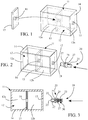
- la
figure 1 est une vue éclatée d'un objet selon l'invention dans une première étape de fabrication, montrant l'insertion d'une paroi intérieure dans un corps creux dudit objet lors d'une opération de moulage, - la
figure 2 est une vue éclatée de l'objet de lafigure 1 une deuxième étape de fabrication, montrant le montage d'un insert musical dans le corps de l'objet obtenu par moulage, - la
figure 3 est une vue en coupe axiale de l'objet de lafigure 2 , - la
figure 4 est une vue éclatée de l'objet de lafigure 2 dans une troisième étape de fabrication, montrant le montage d'un bouchon pour fermer de manière étanche le corps dudit objet, - la
figure 5 est une vue en coupe axiale de l'objet musical selon l'invention obtenu après fabrication, montrant le bouchon assemblé au corps dudit objet et le volume d'air contenu dans ledit corps, - la
figure 6 est une vue en coupe transversale selon l'axe VI-VI à travers la paroi de séparation de l'objet musical de lafigure 5 , et - la
figure 7 est une vue similaire à lafigure 5 montrant ledit objet musical en fonctionnement, une partie du corps dudit objet musical étant comprimée et en dépression et l'autre partie étant expansée et en surpression.
- the
figure 1 is an exploded view of an object according to the invention in a first manufacturing step, showing the insertion of an interior wall into a hollow body of said object during a molding operation, - the
figure 2 is an exploded view of the object of thefigure 1 a second manufacturing step, showing the mounting of a musical insert in the body of the object obtained by molding, - the
figure 3 is an axial sectional view of the object of thefigure 2 , - the
figure 4 is an exploded view of the object of thefigure 2 in a third manufacturing step, showing the fitting of a stopper to seal the body of said object, - the
figure 5 is an axial sectional view of the musical object according to the invention obtained after manufacture, showing the stopper assembled to the body of said object and the volume of air contained in said body, - the
figure 6 is a cross-sectional view along axis VI-VI through the partition wall of the musical object of thefigure 5 , and - the
figure 7 is a view similar tofigure 5 showing said musical object in operation, one part of the body of said musical object being compressed and under pressure and the other part being expanded and under pressure.
En référence aux figures, l'invention concerne un objet musical 10 qui peut avoir plusieurs destinations, comme celles énumérées dans la description de l'état de la technique, sans que cette liste ne soit limitative. L'objet musical 10 est illustré dans les figures sous une forme parallélépipédique simplifiée au maximum, mais peut bien entendu présenter toute autre forme tridimensionnelle, géométrique ou non, fantaisiste ou non, représentant une figurine ou non, cette forme étant définie et choisie en fonction de la destination dudit objet. L'objet musical 10 comporte dans tous les cas un corps 11, creux et compressible, délimitant au moins une cavité intérieure 12 fermée. Le corps 11 dudit objet musical 10 est avantageusement réalisé dans une matière élastomère, telle qu'un caoutchouc naturel ou synthétique, ou toute autre matière techniquement équivalente, c'est-à-dire ayant des propriétés élastiques permettant à l'objet de reprendre sa forme initiale après suppression d'une sollicitation de compression. Il est de préférence fabriqué en une seule pièce, et comporte une paroi extérieure 14 continue, obtenue par moulage comme expliqué plus loin. Bien entendu et selon la complexité de la forme tridimensionnelle dudit objet, il peut être fabriqué en deux ou plusieurs pièces assemblées le long d'un ou de plusieurs plans de joint vissés, soudés, collés, ou assemblés par tout autre moyen technique connu, pour être démontable ou indémontable, en fonction du cahier des charges dudit objet.With reference to the figures, the invention relates to a
L'objet musical 10 comporte avantageusement une paroi intérieure 15 qui a pour fonction de diviser la cavité intérieure 12 en deux chambres 12a, 12b hermétiques et de porter un insert musical 20 pour qu'il soit disposé à l'intérieur dudit corps 11, entre les deux chambres 12a, 12b afin de ne communiquer qu'avec elles, sans aucune communication avec l'environnement extérieur dudit objet. La paroi intérieure 15 est de préférence positionnée dans une zone médiane dudit objet musical 10 pour diviser la cavité intérieure 12 en deux chambres 12a, 12b sensiblement d'égal volume. Ce mode de réalisation est préféré mais n'est pas le seul car les deux chambres pourraient ne pas avoir le même volume sans affecter le fonctionnement dudit insert musical 20. Il convient dans ce cas que la chambre ayant le volume le plus faible ait un volume suffisant pour permettre un transfert de flux d'air suffisant pour permettre à l'insert musical 20 d'émettre un son. A contrario, si le volume de la chambre la plus faible n'est pas suffisant, le déplacement d'air ne pourra pas générer de son. En effet, le volume de ces chambres 12a, 12b définit le flux d'air qui va traverser l'insert musical 20 pour créer un son à chaque sollicitation dudit objet. Pour ce faire, le volume d'air total des deux chambres 12a, 12b de l'objet musical 10 à l'état initial, c'est-à-dire sans sollicitation mécanique, doit être déterminé en fonction de l'élasticité permise par la matière constituant le corps 11 dudit objet et de la forme tridimensionnelle dudit objet musical 10. Cela signifie qu'il ne faut pas mettre les chambres 12a, 12b en surpression à l'état initial dudit objet musical 10, car si le volume d'air total est trop important jusqu'à saturer les chambres, il n'y aura aucune possibilité de déplacement d'air entre les deux chambres 12a, 12b et par conséquent aucune création de son. De même, il ne faut pas mettre les chambres 12a, 12b en dépression à l'état initial dudit objet musical 10, car un volume d'air total trop faible empêchera tout déplacement d'air entre les deux chambres et toute création de son.The
La paroi intérieure 15 comporte en outre un orifice traversant 16 pour recevoir et maintenir en position ledit insert musical 20 qui doit assurer lors de son montage la fermeture hermétique dudit orifice traversant 16, de telle sorte que le flux d'air F transite d'une chambre à l'autre exclusivement au travers de l'insert musical 20 pour lui garantir un fonctionnement optimal. Cet orifice traversant 16 est dans l'exemple représenté positionné au centre de la paroi intérieure 15 permettant de centrer l'insert musical 20 par rapport audit corps 11, sans que cette position ne soit obligatoire. Bien entendu, la position de la paroi intérieure 15, le nombre de parois intérieures 15, la position de l'insert musical 20 et le nombre d'inserts musicaux 20 peuvent varier en fonction de la dimension, de la forme et de la destination de l'objet musical 10. Il est tout à fait envisageable de juxtaposer plusieurs objets musicaux 10, chacun pourvu d'un insert musical 20 différent, dans un dispositif unique pour créer plusieurs tonalités de son en fonction de la zone sollicitée. La paroi intérieure 15 peut être réalisée dans une matière identique ou au moins chimiquement compatible avec la matière dudit corps 11. Elle peut être fabriquée séparément pour être ensuite insérée dans le moule de fabrication dudit corps 11 et ne former qu'une seule pièce avec ledit corps 11 après moulage. Bien entendu, si le corps 11 de l'objet musical 10 est fabriqué en deux ou plusieurs pièces assemblées le long d'un ou de plusieurs plans de joint, la paroi intérieure 15 peut être intégrée dans un plan joint entre deux pièces.The
L'insert musical 20 est conçu pour être logé à l'intérieur de la cavité intérieure 12 du corps 11 et solidarisé à la paroi intérieure 15 dudit objet sans communiquer avec l'environnement extérieur. La cavité intérieure 12 dudit corps 11 est par conséquent fermée de manière étanche, et contient un volume d'air défini et constant. Ce volume d'air reste propre et est exempt de contaminant car il n'est jamais en contact avec l'environnement extérieur lors de l'utilisation de l'objet musical 10. Par voie de conséquence, l'insert musical 20 reste propre également car il est confiné dans un volume hermétiquement fermé, il n'est donc jamais pollué par des contaminants, ni encrassé par des poussières, et son fonctionnement n'est jamais altéré. La conséquence de cette conception est un objet musical 10 offrant une excellente sécurité pour l'utilisateur, puisque l'élément musical 20 n'est jamais accessible, même accidentellement.The
L'insert musical 20 est agencé pour émettre un son lorsqu'il est traversé par un flux d'air F obtenu dès que le corps 11 dudit objet musical 10 est déformé par pression mécanique au droit d'une des chambres 12a, 12b et que le volume d'air contenu dans cette chambre 12a, 12b d'un côté de la paroi intérieure 15 est chassé vers l'autre chambre 12b, 12a de l'autre côté de la paroi intérieure 15 en passant par l'insert musical 20 (
L'insert musical 20, illustré à partir de la
L'insert musical 20 comporte une zone de montage 25, qui peut être médiane ou non, permettant à la fois son emboitement axial dans l'orifice traversant 16 de la paroi intérieure 15, son verrouillage axial dans les deux sens par rapport à cette paroi et l'étanchéité dudit orifice traversant 16. Cette zone de montage 25 comporte à cet effet une gorge 26 apte à recevoir l'épaisseur de ladite paroi intérieure 15, et deux lèvres 27 disposées de part et d'autre de ladite gorge 26 pour d'une part verrouiller la position axiale dans les deux sens de l'insert musical 20 par rapport à la paroi intérieure 15, et d'autre part assurer l'étanchéité à l'air de cet assemblage. Dans l'exemple représenté, la gaine à musique 21 est cylindrique et la zone de montage 25 est annulaire. Ainsi, le diamètre intérieur de la gorge 26 doit être sensiblement égal, voire légèrement supérieur au diamètre de l'orifice traversant 16 pour assurer un montage serré. De même, la largeur de la gorge 26 doit être sensiblement égale voire légèrement inférieure à l'épaisseur de la paroi intérieure 15 pour plaquer sous pression les lèvres 27 contre les deux faces opposées de ladite paroi. En outre, le diamètre extérieur des lèvres 27 doit être supérieur au diamètre de l'orifice traversant 16 pour contribuer à l'étanchéité à l'air de cet assemblage. Bien entendu, tout autre moyen technique équivalent peut convenir. De même, la forme cylindrique de la gaine à musique 21 et la forme annulaire de la zone de montage 25 ne sont pas limitatives et peuvent être différentes tout en assurant les fonctions prévues.The
L'élément musical 30 contenu dans l'insert musical 20 appartient aux petits instruments à vent. Dans l'exemple illustré, il est constitué d'un sifflet à double entrée, dans lequel le son est créé par la vibration d'une anche au passage du flux d'air F circulant dans les deux directions opposées selon que l'on comprime l'une ou l'autre chambre 12a, 12b. Il fait partie des éléments connus et ne sera pas décrit plus en détail. Il peut être réalisé en bois, en roseau, en métal, en matière synthétique telle qu'une matière thermoplastique, en matière composite, ou en une combinaison d'au moins deux de ces matières. Bien entendu, toute autre forme et/ou conception d'élément musical peut convenir.The
Le procédé de fabrication de l'objet musical 10 selon l'invention comporte une opération de moulage du corps 11 de l'objet dans un moule de fabrication creux (non représenté), dont la surface intérieure correspondant à l'empreinte tridimensionnelle dudit objet. On peut choisir une technique de rotomoulage ou moulage par rotation du moule de fabrication, qui permet de fabriquer des pièces creuses en une seule partie, sans plan de joint, par mise en forme d'une matière plastique en fusion contre la paroi intérieure d'un moule de fabrication creux. On peut également utiliser une technique d'injection en deux pièces avec une étape de collage des deux pièces sur une presse suivant un plan de joint. On peut encore utiliser une technique de soufflage, si la matière plastique utilisée s'y prête. Dans la présente invention, on peut utiliser comme matières plastiques principales un élastomère tel qu'un caoutchouc naturel ou synthétique, sans que cet exemple ne soit limitatif. Le moule de fabrication est généralement réalisé en deux parties, sans que cet exemple ne soit limitatif, et est équipé d'un évent ou plus, assurant l'équilibre de la pression à l'intérieur du moule. On charge une dose de matières plastiques dans le moule avant sa fermeture, définie en fonction de l'épaisseur de la paroi 14 dudit objet à fabriquer. La phase de moulage comporte une étape de chauffe et une étape de refroidissement. L'évent permet d'évacuer les gaz contenus dans le moule à l'extérieur du moule lors de l'étape de chauffe, puis à l'air de rentrer dans le moule lors de l'étape de refroidissement évitant ainsi à la pièce d'être en dépression.The method of manufacturing the
Préalablement à l'étape de moulage du corps 11 dudit objet, on ajoute à l'intérieur du moule, par exemple entre les deux parties du moule, la paroi intérieure 15 qui a été fabriquée séparément. On peut dans ce cas prévoir que l'évent prévu dans le moule se prolonge jusqu'à l'intérieur de l'orifice traversant 16 de la paroi intérieure 15 pour éviter que cet orifice ne se bouche par la matière plastique en fusion. Ainsi, à l'issue de la phase de moulage, et après ouverture du moule, on obtient le corps 11 dudit objet, selon la
Après la phase de maturation ou séchage complet dudit corps 11, on introduit l'insert musical 20 à l'intérieur du corps 11 par le trou d'évent 13 laissé dans la paroi extérieure 14 dudit corps 11 par l'évent du moule de fabrication, comme le montrent les
L'objet musical 10 obtenu par le procédé de fabrication selon l'invention est illustré dans les
Il apparait clairement de ce qui précède que l'invention permet d'atteindre les buts fixée. Notamment, cet objet musical 10 peut émettre des sons sans être en communication avec l'environnement extérieur, par un simple transfert d'air entre deux chambres 12a, 12b hermétiquement fermées via un insert musical 20. De ce fait, cet objet musical 10 est dit « propre » étant donné que son volume intérieur et son insert musical 20 sont protégés de l'utilisateur et de l'environnement extérieur par son corps 11 fermé de manière hermétique, évitant tout risque de contamination. Il peut en outre être facilement lavé, nettoyé, désinfecté pour éviter là encore tout risque de contamination par le toucher. Cet objet musical 10 peut être décliné dans tout type d'applications aussi bien dans le domaine des secours comme alerte sonore, dans le domaine du sport comme moyen d'arbitrage, dans le domaine du loisir comme instrument de musique, dans le domaine ludique comme jouet couineur ou siffleur pour enfants et animaux domestiques, etc. Sa conception particulière fait de cet objet musical 10 un dispositif totalement sécurisé pour l'usager puisque l'insert musical 20 n'est pas accessible, même accidentellement.It is clear from the foregoing that the invention makes it possible to achieve the objectives set. In particular, this
La présente invention n'est pas limitée à l'exemple de réalisation décrit mais s'étend à toute modification et variante évidentes pour un homme du métier dans le cadre du champ de protection tel que défini par les revendications suivantes.The present invention is not limited to the exemplary embodiment described but extends to any modification and variant obvious to a person skilled in the art within the framework of the protective field as defined by the following claims.
Claims (11)
- Method for producing a musical instrument (10), said musical instrument comprising a hollow and compressible body (11) made of a flexible and elastic material, delimiting an internal cavity (12), an internal wall (15) arranged inside said body (11) in order to divide said internal cavity (12) into two chambers (12a, 12b), and a musical insert (20) mounted through said internal wall (15) in order to place said chambers (12a, 12b) in communication with one another and designed to emit a sound when passed through by an air flow (F), said air flow being generated by a mechanical pressure exerted on said body (11) at the level of one of the chambers, in which method the body (11) of said musical instrument (10) is made, using a moulding technique, from an elastomer material shaped in a hollow production mould provided with a vent, the internal volume of said mould corresponding to the three-dimensional impression of said body (11), characterised in that said internal wall (15) provided with a through-orifice (16) designed to receive and hold said musical insert (20) in position is produced separately, in that, prior to the step of moulding said body (11), said internal wall (15) is added into said production mould such that the periphery thereof is overmoulded by said body (11) during the moulding step, in that, after the moulding operation for said body (11), said musical insert (20) is inserted into said body (11) via the vent hole (13) left in the external wall (14) of said body (11) by the vent of said production mould, in order to interlock same in the internal wall (15) through said through-orifice (16) and simultaneously hermetically seal said through-orifice, and in that, after mounting the musical insert (20) inside said body (11), said vent hole (13) is closed by a plug (17) in order to sealingly plug and hermetically seal said internal cavity (12), such that said musical insert (20) is arranged inside said body (11), between the two chambers (12a, 12b) so as to communicate solely therewith, without any communication with the environment external to said musical instrument (10).
- Production method according to claim 1, characterised in that said internal cavity (12) is filled with a determined and constant total air volume taking into account the elasticity of said material forming said body (11) and the three-dimensional shape of said body (11) in order to allow air to be displaced between the two chambers (12a, 12b) when a mechanical pressure is exerted on said body (11) at the level of one of the chambers and thus allow a sound to be created each time said instrument is mechanically stressed.
- Production method according to claim 1, characterised in that the internal wall (15) and the body (11) of said musical instrument (10) are made of a similar, identical, or compatible elastomer material, allowing the two materials to fuse during the moulding operation.
- Production method according to claim 3, characterised in that said elastomer material is chosen from natural rubbers, synthetic rubbers, and thermoplastic elastomers.
- Production method according to claim 1, characterised in that said moulding technique is a rotational moulding technique.
- Production method according to claim 1, characterised in that a mounting area (25) complementary to the through-orifice (16) provided in said internal wall (15) is provided on said musical insert (20) and designed to hermetically seal said through-orifice (16).
- Production method according to claim 6, characterised in that said mounting area (25) is produced in the form of a groove (26) designed to receive said through-orifice (16), and two lips (27) arranged on either side of said groove (26) and designed to be pressed against the opposite faces of said internal wall (15), to hold said musical insert (20) in the mounting position relative to said internal wall (15) and to hermetically seal said through-orifice (16).
- Musical instrument (10) obtained by the production method according to any of the preceding claims, said musical instrument comprising a hollow and compressible body (11) made of a flexible and elastic material, delimiting an internal cavity (12), an internal wall (15) arranged inside said body (11) in order to divide said internal cavity (12) into two chambers (12a, 12b), and a musical insert (20) mounted through said internal wall (15) in order to place said chambers (12a, 12b) in communication with one another and designed to emit a sound when passed through by an air flow (F), said air flow being generated by a mechanical pressure exerted on said body (11) at the level of one of the chambers, characterised in that said internal wall (15) has its periphery overmoulded by said body (11) and comprises a through-orifice (16) designed to receive and hold said musical insert (20) in position, in that said musical insert (20) is designed to hermetically seal said through-orifice (16), and in that said body (11) comprises a vent hole (13) that is hermetically sealed by a plug (17) such that said musical insert (20) is arranged inside said body (11), between the two chambers (12a, 12b) so as to communicate solely therewith, without any communication with the environment external to said musical instrument (10).
- Musical instrument according to claim 8, characterised in that said internal cavity (12) is filled with a determined and constant total air volume taking into account the elasticity of said material forming said body (11) and the three-dimensional shape of said body (11) in order to allow air to be displaced between the two chambers (12a, 12b) when a mechanical pressure is exerted on said body (11) at the level of one of the chambers and thus allow a sound to be created each time said instrument is mechanically stressed.
- Musical instrument according to claim 8, characterised in that said musical insert (20) comprises a mounting area (25) complementary to the through-orifice (16) provided in said internal wall (15) and designed to hermetically seal said orifice.
- Musical instrument according to claim 10, characterised in that said mounting area (25) comprises a groove (26) designed to receive said through-orifice (16), and two lips (27) arranged on either side of said groove (26) and designed to be pressed against the opposite faces of said internal wall (15), to hold said musical insert (20) in the mounting position relative to said internal wall (15) and to hermetically seal said through-orifice (16).
Applications Claiming Priority (2)
| Application Number | Priority Date | Filing Date | Title |
|---|---|---|---|
| FR1761581A FR3074603B1 (en) | 2017-12-04 | 2017-12-04 | PROCESS FOR MANUFACTURING A MUSICAL OBJECT AND OBTAINED MUSICAL OBJECT |
| PCT/EP2018/083371 WO2019110520A1 (en) | 2017-12-04 | 2018-12-03 | Method for producing a musical instrument and musical instrument obtained thereby |
Publications (2)
| Publication Number | Publication Date |
|---|---|
| EP3703836A1 EP3703836A1 (en) | 2020-09-09 |
| EP3703836B1 true EP3703836B1 (en) | 2021-11-17 |
Family
ID=61224074
Family Applications (1)
| Application Number | Title | Priority Date | Filing Date |
|---|---|---|---|
| EP18811264.3A Active EP3703836B1 (en) | 2017-12-04 | 2018-12-03 | Method for producing a musical instrument and musical instrument obtained thereby |
Country Status (8)
| Country | Link |
|---|---|
| US (1) | US11676566B2 (en) |
| EP (1) | EP3703836B1 (en) |
| CN (1) | CN111432903B (en) |
| DK (1) | DK3703836T3 (en) |
| ES (1) | ES2899861T3 (en) |
| FR (1) | FR3074603B1 (en) |
| MA (1) | MA50521B1 (en) |
| WO (1) | WO2019110520A1 (en) |
Family Cites Families (27)
| Publication number | Priority date | Publication date | Assignee | Title |
|---|---|---|---|---|
| US1461193A (en) * | 1922-02-10 | 1923-07-10 | Larsen Hans | Pneumatic toy |
| FR587841A (en) * | 1924-10-22 | 1925-04-24 | Method of securing whistles or other sound devices inside toys and other hollow objects made of rubber or other elastic material | |
| NL51000C (en) * | 1937-12-10 | |||
| US2712201A (en) * | 1952-09-09 | 1955-07-05 | Wintriss Inc | Whistle for pneumatic toys |
| US2817116A (en) * | 1955-04-08 | 1957-12-24 | Theodore A Miller | Mold for making a sound producing article |
| US4380134A (en) * | 1976-09-28 | 1983-04-19 | Taluba Anthony P | Molded squeeze toy including whistle |
| AU714503B2 (en) * | 1998-04-02 | 2000-01-06 | Wayne Turrong Peckham | A method of making a musical instrument |
| FR2793152B1 (en) | 1999-05-07 | 2001-07-20 | Michel Flageollet | MANUAL WHISTLE |
| US8322308B2 (en) | 2000-03-16 | 2012-12-04 | Jon K Curry | Animal toy with adjustable squeaker |
| US9345234B2 (en) * | 2000-03-16 | 2016-05-24 | Jon K. Curry | Fabric covered elastic polymer animal toy with soft pliable fabric head |
| US6935274B1 (en) * | 2002-06-25 | 2005-08-30 | Steven M. Rothschild | Pet toy |
| US20120103274A1 (en) | 2010-10-28 | 2012-05-03 | Curry Jon K | Animal toy with induction charging system |
| US7264533B2 (en) * | 2004-06-18 | 2007-09-04 | T. K. Wong & Associates Ltd. | Bubble-squeezing toy |
| US8235762B2 (en) * | 2005-12-20 | 2012-08-07 | J.W. Pet Company, Inc. | Mounting arrangement for squeaker |
| US7833079B2 (en) * | 2004-07-13 | 2010-11-16 | J.W. Pet Company, Inc. | Noise producing toy structure |
| US7066779B2 (en) * | 2004-07-13 | 2006-06-27 | Jw Pet Company | Mounting arrangement for squeakers |
| CN201006306Y (en) * | 2007-03-19 | 2008-01-16 | 台州中泰海洋广场有限公司 | Sounding toy stick |
| US8468977B2 (en) | 2007-08-07 | 2013-06-25 | The Kong Company, Llc | Pet toy with noise making instrument |
| US8314318B2 (en) * | 2008-12-12 | 2012-11-20 | University Of Washington | Unified octave/register key and vent for musical wind instruments |
| JP5866665B2 (en) * | 2011-09-27 | 2016-02-17 | 三共理研株式会社 | Whistle toy |
| US20130097901A1 (en) * | 2011-10-05 | 2013-04-25 | John Scott Cooper | Play toys and techniques for fabricating play toys |
| US9370167B2 (en) * | 2012-10-18 | 2016-06-21 | Otomik Products, Inc. | Pet toy with squeaker mechanism |
| CN204217652U (en) * | 2014-09-25 | 2015-03-25 | 上海悦远贸易有限公司 | A kind of pet toy |
| CN204582541U (en) * | 2015-01-15 | 2015-08-26 | 宁波市阳普生进出口有限公司 | A kind of vinyl toy |
| WO2017045166A1 (en) | 2015-09-16 | 2017-03-23 | 尚平 | Waterproof electronic whistle |
| US10681899B1 (en) * | 2016-06-15 | 2020-06-16 | Gramercy Products, Inc. | Squeaker assembly for child and pet toys |
| FR3071171B1 (en) * | 2017-09-15 | 2019-09-13 | Sophie La Girafe | MUSICAL INSERT, METHOD FOR MANUFACTURING A MUSICAL TOY PROVIDED WITH SAID INSERT AND MUSICAL TOY OBTAINED BY SAID METHOD |
-
2017
- 2017-12-04 FR FR1761581A patent/FR3074603B1/en not_active Expired - Fee Related
-
2018
- 2018-12-03 US US16/763,093 patent/US11676566B2/en active Active
- 2018-12-03 CN CN201880078045.7A patent/CN111432903B/en active Active
- 2018-12-03 EP EP18811264.3A patent/EP3703836B1/en active Active
- 2018-12-03 DK DK18811264.3T patent/DK3703836T3/en active
- 2018-12-03 MA MA50521A patent/MA50521B1/en unknown
- 2018-12-03 WO PCT/EP2018/083371 patent/WO2019110520A1/en unknown
- 2018-12-03 ES ES18811264T patent/ES2899861T3/en active Active
Also Published As
| Publication number | Publication date |
|---|---|
| FR3074603A1 (en) | 2019-06-07 |
| EP3703836A1 (en) | 2020-09-09 |
| MA50521B1 (en) | 2021-12-31 |
| WO2019110520A1 (en) | 2019-06-13 |
| US20200365130A1 (en) | 2020-11-19 |
| CN111432903B (en) | 2022-02-11 |
| CN111432903A (en) | 2020-07-17 |
| US11676566B2 (en) | 2023-06-13 |
| ES2899861T3 (en) | 2022-03-15 |
| MA50521A (en) | 2020-09-09 |
| DK3703836T3 (en) | 2022-01-03 |
| FR3074603B1 (en) | 2021-03-19 |
Similar Documents
| Publication | Publication Date | Title |
|---|---|---|
| EP1193186B1 (en) | Device for the reversible fixation of a container on a support and container equipped with such a device | |
| EP0816253A1 (en) | Device and process for the separate storage of at least two products, for the mixture and distribution of these products | |
| FR2972337A1 (en) | CONTAINER, IN PARTICULAR POT OF COSMETIC PRODUCT, AND METHOD OF MANUFACTURING THE SAME | |
| FR2526757A1 (en) | SYNTHETIC RESIN CONTAINER AND PROCESS FOR FORMING SAME | |
| FR2787546A1 (en) | VALVE ELEMENT AND MANUFACTURING METHOD THEREOF | |
| EP3703836B1 (en) | Method for producing a musical instrument and musical instrument obtained thereby | |
| EP0959334B1 (en) | Manufacturing process of an apparatus or instrument by overmoulding and apparatus or instrument obtained by such process | |
| EP0764590B1 (en) | Conditioning and dispensing device | |
| FR3071171B1 (en) | MUSICAL INSERT, METHOD FOR MANUFACTURING A MUSICAL TOY PROVIDED WITH SAID INSERT AND MUSICAL TOY OBTAINED BY SAID METHOD | |
| EP1100624B1 (en) | Fluid product dispensing device | |
| EP0940150B1 (en) | Nose mucus aspiration device | |
| FR2724314A1 (en) | PACKAGING PACKAGE FOR CONDOMS | |
| FR2838152A1 (en) | IMPROVED HINGE AND PLUG HAVING SUCH A HINGE | |
| EP0825128A2 (en) | Element for connecting a dispensing device to the neck of a container | |
| FR2973781A1 (en) | SLIDING SHUTTER CAP HAVING MULTIPLE DISTRIBUTION HOLES | |
| EP1094372B1 (en) | Control knob | |
| CA2778296A1 (en) | Hygienic pacifier | |
| EP0485289A1 (en) | Packaging for dangerous products, fragile contaner | |
| CA1315311C (en) | Self-contained valve for enclosed casing, fabrication process thereof and means allowing usage of that process | |
| EP1799423A1 (en) | Injection moulding device with increased tightness between the injection nozzle and moulding matrix | |
| FR2821289A1 (en) | WHEEL, PARTICULARLY FOR LIGHT VEHICLES, AND MANUFACTURING METHOD THEREOF | |
| FR2955765A1 (en) | Baby feeder, has coating with layers that respectively cover entire internal surfaces of walls and entire internal surface or partial external surface of uprights, and membranes connecting layers by filling spaces between posts | |
| FR2587225A1 (en) | PERFUMED BALLOON AND VALVE | |
| FR2955766A1 (en) | Baby feeder, has receiving wall with notch that is in communication with exterior air, and peripheral free space that is defined between groove and nipple, and in communication with opening when membrane is in air intake position | |
| FR2866832A1 (en) | Volatile substance e.g. perfume, diffuser for motor vehicle aerator, has lateral wall extending from lower edge in flared manner, where lower edge has protrusion to maintain diffuser on boundary of aerator opening |
Legal Events
| Date | Code | Title | Description |
|---|---|---|---|
| STAA | Information on the status of an ep patent application or granted ep patent |
Free format text: STATUS: UNKNOWN |
|
| STAA | Information on the status of an ep patent application or granted ep patent |
Free format text: STATUS: THE INTERNATIONAL PUBLICATION HAS BEEN MADE |
|
| PUAI | Public reference made under article 153(3) epc to a published international application that has entered the european phase |
Free format text: ORIGINAL CODE: 0009012 |
|
| STAA | Information on the status of an ep patent application or granted ep patent |
Free format text: STATUS: REQUEST FOR EXAMINATION WAS MADE |
|
| 17P | Request for examination filed |
Effective date: 20200603 |
|
| AK | Designated contracting states |
Kind code of ref document: A1 Designated state(s): AL AT BE BG CH CY CZ DE DK EE ES FI FR GB GR HR HU IE IS IT LI LT LU LV MC MK MT NL NO PL PT RO RS SE SI SK SM TR |
|
| AX | Request for extension of the european patent |
Extension state: BA ME |
|
| DAX | Request for extension of the european patent (deleted) | ||
| RAV | Requested validation state of the european patent: fee paid |
Extension state: MA Effective date: 20200603 |
|
| REG | Reference to a national code |
Ref country code: DE Ref legal event code: R079 Ref document number: 602018026933 Country of ref document: DE Free format text: PREVIOUS MAIN CLASS: A63H0003280000 Ipc: G10K0015040000 |
|
| GRAP | Despatch of communication of intention to grant a patent |
Free format text: ORIGINAL CODE: EPIDOSNIGR1 |
|
| STAA | Information on the status of an ep patent application or granted ep patent |
Free format text: STATUS: GRANT OF PATENT IS INTENDED |
|
| RIC1 | Information provided on ipc code assigned before grant |
Ipc: G10K 15/04 20060101AFI20210622BHEP Ipc: A63H 5/00 20060101ALI20210622BHEP Ipc: A01K 15/02 20060101ALI20210622BHEP |
|
| INTG | Intention to grant announced |
Effective date: 20210715 |
|
| GRAS | Grant fee paid |
Free format text: ORIGINAL CODE: EPIDOSNIGR3 |
|
| GRAA | (expected) grant |
Free format text: ORIGINAL CODE: 0009210 |
|
| STAA | Information on the status of an ep patent application or granted ep patent |
Free format text: STATUS: THE PATENT HAS BEEN GRANTED |
|
| AK | Designated contracting states |
Kind code of ref document: B1 Designated state(s): AL AT BE BG CH CY CZ DE DK EE ES FI FR GB GR HR HU IE IS IT LI LT LU LV MC MK MT NL NO PL PT RO RS SE SI SK SM TR |
|
| REG | Reference to a national code |
Ref country code: GB Ref legal event code: FG4D Free format text: NOT ENGLISH |
|
| REG | Reference to a national code |
Ref country code: IE Ref legal event code: FG4D Free format text: LANGUAGE OF EP DOCUMENT: FRENCH |
|
| REG | Reference to a national code |
Ref country code: DE Ref legal event code: R096 Ref document number: 602018026933 Country of ref document: DE |
|
| REG | Reference to a national code |
Ref country code: AT Ref legal event code: REF Ref document number: 1448737 Country of ref document: AT Kind code of ref document: T Effective date: 20211215 |
|
| REG | Reference to a national code |
Ref country code: NL Ref legal event code: FP |
|
| REG | Reference to a national code |
Ref country code: MA Ref legal event code: VAGR Ref document number: 50521 Country of ref document: MA Kind code of ref document: B1 |
|
| REG | Reference to a national code |
Ref country code: DK Ref legal event code: T3 Effective date: 20211221 |
|
| REG | Reference to a national code |
Ref country code: LT Ref legal event code: MG9D |
|
| REG | Reference to a national code |
Ref country code: ES Ref legal event code: FG2A Ref document number: 2899861 Country of ref document: ES Kind code of ref document: T3 Effective date: 20220315 |
|
| REG | Reference to a national code |
Ref country code: AT Ref legal event code: MK05 Ref document number: 1448737 Country of ref document: AT Kind code of ref document: T Effective date: 20211117 |
|
| PG25 | Lapsed in a contracting state [announced via postgrant information from national office to epo] |
Ref country code: RS Free format text: LAPSE BECAUSE OF FAILURE TO SUBMIT A TRANSLATION OF THE DESCRIPTION OR TO PAY THE FEE WITHIN THE PRESCRIBED TIME-LIMIT Effective date: 20211117 Ref country code: LT Free format text: LAPSE BECAUSE OF FAILURE TO SUBMIT A TRANSLATION OF THE DESCRIPTION OR TO PAY THE FEE WITHIN THE PRESCRIBED TIME-LIMIT Effective date: 20211117 Ref country code: FI Free format text: LAPSE BECAUSE OF FAILURE TO SUBMIT A TRANSLATION OF THE DESCRIPTION OR TO PAY THE FEE WITHIN THE PRESCRIBED TIME-LIMIT Effective date: 20211117 Ref country code: BG Free format text: LAPSE BECAUSE OF FAILURE TO SUBMIT A TRANSLATION OF THE DESCRIPTION OR TO PAY THE FEE WITHIN THE PRESCRIBED TIME-LIMIT Effective date: 20220217 Ref country code: AT Free format text: LAPSE BECAUSE OF FAILURE TO SUBMIT A TRANSLATION OF THE DESCRIPTION OR TO PAY THE FEE WITHIN THE PRESCRIBED TIME-LIMIT Effective date: 20211117 |
|
| PG25 | Lapsed in a contracting state [announced via postgrant information from national office to epo] |
Ref country code: IS Free format text: LAPSE BECAUSE OF FAILURE TO SUBMIT A TRANSLATION OF THE DESCRIPTION OR TO PAY THE FEE WITHIN THE PRESCRIBED TIME-LIMIT Effective date: 20220317 Ref country code: SE Free format text: LAPSE BECAUSE OF FAILURE TO SUBMIT A TRANSLATION OF THE DESCRIPTION OR TO PAY THE FEE WITHIN THE PRESCRIBED TIME-LIMIT Effective date: 20211117 Ref country code: PT Free format text: LAPSE BECAUSE OF FAILURE TO SUBMIT A TRANSLATION OF THE DESCRIPTION OR TO PAY THE FEE WITHIN THE PRESCRIBED TIME-LIMIT Effective date: 20220317 Ref country code: PL Free format text: LAPSE BECAUSE OF FAILURE TO SUBMIT A TRANSLATION OF THE DESCRIPTION OR TO PAY THE FEE WITHIN THE PRESCRIBED TIME-LIMIT Effective date: 20211117 Ref country code: NO Free format text: LAPSE BECAUSE OF FAILURE TO SUBMIT A TRANSLATION OF THE DESCRIPTION OR TO PAY THE FEE WITHIN THE PRESCRIBED TIME-LIMIT Effective date: 20220217 Ref country code: LV Free format text: LAPSE BECAUSE OF FAILURE TO SUBMIT A TRANSLATION OF THE DESCRIPTION OR TO PAY THE FEE WITHIN THE PRESCRIBED TIME-LIMIT Effective date: 20211117 Ref country code: HR Free format text: LAPSE BECAUSE OF FAILURE TO SUBMIT A TRANSLATION OF THE DESCRIPTION OR TO PAY THE FEE WITHIN THE PRESCRIBED TIME-LIMIT Effective date: 20211117 Ref country code: GR Free format text: LAPSE BECAUSE OF FAILURE TO SUBMIT A TRANSLATION OF THE DESCRIPTION OR TO PAY THE FEE WITHIN THE PRESCRIBED TIME-LIMIT Effective date: 20220218 |
|
| PG25 | Lapsed in a contracting state [announced via postgrant information from national office to epo] |
Ref country code: SM Free format text: LAPSE BECAUSE OF FAILURE TO SUBMIT A TRANSLATION OF THE DESCRIPTION OR TO PAY THE FEE WITHIN THE PRESCRIBED TIME-LIMIT Effective date: 20211117 Ref country code: SK Free format text: LAPSE BECAUSE OF FAILURE TO SUBMIT A TRANSLATION OF THE DESCRIPTION OR TO PAY THE FEE WITHIN THE PRESCRIBED TIME-LIMIT Effective date: 20211117 Ref country code: RO Free format text: LAPSE BECAUSE OF FAILURE TO SUBMIT A TRANSLATION OF THE DESCRIPTION OR TO PAY THE FEE WITHIN THE PRESCRIBED TIME-LIMIT Effective date: 20211117 Ref country code: EE Free format text: LAPSE BECAUSE OF FAILURE TO SUBMIT A TRANSLATION OF THE DESCRIPTION OR TO PAY THE FEE WITHIN THE PRESCRIBED TIME-LIMIT Effective date: 20211117 Ref country code: CZ Free format text: LAPSE BECAUSE OF FAILURE TO SUBMIT A TRANSLATION OF THE DESCRIPTION OR TO PAY THE FEE WITHIN THE PRESCRIBED TIME-LIMIT Effective date: 20211117 |
|
| REG | Reference to a national code |
Ref country code: DE Ref legal event code: R097 Ref document number: 602018026933 Country of ref document: DE |
|
| PG25 | Lapsed in a contracting state [announced via postgrant information from national office to epo] |
Ref country code: MC Free format text: LAPSE BECAUSE OF FAILURE TO SUBMIT A TRANSLATION OF THE DESCRIPTION OR TO PAY THE FEE WITHIN THE PRESCRIBED TIME-LIMIT Effective date: 20211117 |
|
| PLBE | No opposition filed within time limit |
Free format text: ORIGINAL CODE: 0009261 |
|
| STAA | Information on the status of an ep patent application or granted ep patent |
Free format text: STATUS: NO OPPOSITION FILED WITHIN TIME LIMIT |
|
| 26N | No opposition filed |
Effective date: 20220818 |
|
| PG25 | Lapsed in a contracting state [announced via postgrant information from national office to epo] |
Ref country code: LU Free format text: LAPSE BECAUSE OF NON-PAYMENT OF DUE FEES Effective date: 20211203 Ref country code: IE Free format text: LAPSE BECAUSE OF NON-PAYMENT OF DUE FEES Effective date: 20211203 Ref country code: AL Free format text: LAPSE BECAUSE OF FAILURE TO SUBMIT A TRANSLATION OF THE DESCRIPTION OR TO PAY THE FEE WITHIN THE PRESCRIBED TIME-LIMIT Effective date: 20211117 |
|
| PG25 | Lapsed in a contracting state [announced via postgrant information from national office to epo] |
Ref country code: SI Free format text: LAPSE BECAUSE OF FAILURE TO SUBMIT A TRANSLATION OF THE DESCRIPTION OR TO PAY THE FEE WITHIN THE PRESCRIBED TIME-LIMIT Effective date: 20211117 |
|
| PGFP | Annual fee paid to national office [announced via postgrant information from national office to epo] |
Ref country code: BE Payment date: 20221213 Year of fee payment: 5 |
|
| PGFP | Annual fee paid to national office [announced via postgrant information from national office to epo] |
Ref country code: ES Payment date: 20230105 Year of fee payment: 5 Ref country code: CH Payment date: 20221229 Year of fee payment: 5 |
|
| PG25 | Lapsed in a contracting state [announced via postgrant information from national office to epo] |
Ref country code: IT Free format text: LAPSE BECAUSE OF FAILURE TO SUBMIT A TRANSLATION OF THE DESCRIPTION OR TO PAY THE FEE WITHIN THE PRESCRIBED TIME-LIMIT Effective date: 20211117 |
|
| PG25 | Lapsed in a contracting state [announced via postgrant information from national office to epo] |
Ref country code: CY Free format text: LAPSE BECAUSE OF FAILURE TO SUBMIT A TRANSLATION OF THE DESCRIPTION OR TO PAY THE FEE WITHIN THE PRESCRIBED TIME-LIMIT Effective date: 20211117 |
|
| P01 | Opt-out of the competence of the unified patent court (upc) registered |
Effective date: 20230527 |
|
| PG25 | Lapsed in a contracting state [announced via postgrant information from national office to epo] |
Ref country code: HU Free format text: LAPSE BECAUSE OF FAILURE TO SUBMIT A TRANSLATION OF THE DESCRIPTION OR TO PAY THE FEE WITHIN THE PRESCRIBED TIME-LIMIT; INVALID AB INITIO Effective date: 20181203 |
|
| PGFP | Annual fee paid to national office [announced via postgrant information from national office to epo] |
Ref country code: NL Payment date: 20231124 Year of fee payment: 6 |
|
| PGFP | Annual fee paid to national office [announced via postgrant information from national office to epo] |
Ref country code: GB Payment date: 20231221 Year of fee payment: 6 |
|
| PGFP | Annual fee paid to national office [announced via postgrant information from national office to epo] |
Ref country code: TR Payment date: 20231122 Year of fee payment: 6 Ref country code: FR Payment date: 20231224 Year of fee payment: 6 Ref country code: DK Payment date: 20231129 Year of fee payment: 6 Ref country code: DE Payment date: 20231208 Year of fee payment: 6 |
|
| PGFP | Annual fee paid to national office [announced via postgrant information from national office to epo] |
Ref country code: BE Payment date: 20231212 Year of fee payment: 6 |