EP3703084A1 - Kohlenstoffnanoröhrchenbeschichteter elektrischer draht und spule - Google Patents
Kohlenstoffnanoröhrchenbeschichteter elektrischer draht und spule Download PDFInfo
- Publication number
- EP3703084A1 EP3703084A1 EP18870309.4A EP18870309A EP3703084A1 EP 3703084 A1 EP3703084 A1 EP 3703084A1 EP 18870309 A EP18870309 A EP 18870309A EP 3703084 A1 EP3703084 A1 EP 3703084A1
- Authority
- EP
- European Patent Office
- Prior art keywords
- wire
- carbon nanotube
- equal
- cnt
- insulating coating
- Prior art date
- Legal status (The legal status is an assumption and is not a legal conclusion. Google has not performed a legal analysis and makes no representation as to the accuracy of the status listed.)
- Withdrawn
Links
- 239000002041 carbon nanotube Substances 0.000 title claims abstract description 174
- OKTJSMMVPCPJKN-UHFFFAOYSA-N Carbon Chemical compound [C] OKTJSMMVPCPJKN-UHFFFAOYSA-N 0.000 title claims abstract description 105
- 229910021393 carbon nanotube Inorganic materials 0.000 title claims abstract description 104
- 239000011247 coating layer Substances 0.000 claims abstract description 119
- 239000011248 coating agent Substances 0.000 claims abstract description 22
- 238000000576 coating method Methods 0.000 claims abstract description 22
- 239000000463 material Substances 0.000 claims description 25
- 238000000235 small-angle X-ray scattering Methods 0.000 claims description 15
- 238000000333 X-ray scattering Methods 0.000 claims description 7
- 238000004804 winding Methods 0.000 claims description 5
- 238000009413 insulation Methods 0.000 abstract description 29
- 230000017525 heat dissipation Effects 0.000 abstract description 27
- 229910052782 aluminium Inorganic materials 0.000 abstract description 23
- XAGFODPZIPBFFR-UHFFFAOYSA-N aluminium Chemical compound [Al] XAGFODPZIPBFFR-UHFFFAOYSA-N 0.000 abstract description 23
- RYGMFSIKBFXOCR-UHFFFAOYSA-N Copper Chemical compound [Cu] RYGMFSIKBFXOCR-UHFFFAOYSA-N 0.000 abstract description 21
- 239000010949 copper Substances 0.000 abstract description 20
- 229910052802 copper Inorganic materials 0.000 abstract description 17
- 238000005299 abrasion Methods 0.000 abstract description 16
- 239000013585 weight reducing agent Substances 0.000 abstract description 6
- 239000010410 layer Substances 0.000 description 33
- 238000000034 method Methods 0.000 description 30
- 230000006399 behavior Effects 0.000 description 18
- 229920002635 polyurethane Polymers 0.000 description 15
- 239000004814 polyurethane Substances 0.000 description 15
- 238000012360 testing method Methods 0.000 description 14
- 238000005259 measurement Methods 0.000 description 13
- 229910052751 metal Inorganic materials 0.000 description 13
- 239000002184 metal Substances 0.000 description 13
- 230000000052 comparative effect Effects 0.000 description 12
- 230000002093 peripheral effect Effects 0.000 description 12
- -1 polytetrafluoroethylene Polymers 0.000 description 11
- 239000004743 Polypropylene Substances 0.000 description 10
- 238000012545 processing Methods 0.000 description 10
- 229920005989 resin Polymers 0.000 description 10
- 239000011347 resin Substances 0.000 description 10
- 238000009987 spinning Methods 0.000 description 10
- 229920001155 polypropylene Polymers 0.000 description 9
- 239000004642 Polyimide Substances 0.000 description 8
- 229920001721 polyimide Polymers 0.000 description 8
- 239000013598 vector Substances 0.000 description 8
- 238000004736 wide-angle X-ray diffraction Methods 0.000 description 8
- 229920005992 thermoplastic resin Polymers 0.000 description 7
- 238000004519 manufacturing process Methods 0.000 description 6
- 238000012935 Averaging Methods 0.000 description 4
- 238000005336 cracking Methods 0.000 description 4
- 238000010586 diagram Methods 0.000 description 4
- 238000000578 dry spinning Methods 0.000 description 4
- 238000001878 scanning electron micrograph Methods 0.000 description 4
- 239000002356 single layer Substances 0.000 description 4
- 239000007787 solid Substances 0.000 description 4
- 229920001187 thermosetting polymer Polymers 0.000 description 4
- 238000002166 wet spinning Methods 0.000 description 4
- 238000005452 bending Methods 0.000 description 3
- 230000007423 decrease Effects 0.000 description 3
- 230000000694 effects Effects 0.000 description 3
- 238000005516 engineering process Methods 0.000 description 3
- 238000001125 extrusion Methods 0.000 description 3
- 239000004973 liquid crystal related substance Substances 0.000 description 3
- 229910000881 Cu alloy Inorganic materials 0.000 description 2
- 239000003054 catalyst Substances 0.000 description 2
- 230000000593 degrading effect Effects 0.000 description 2
- 238000013461 design Methods 0.000 description 2
- 239000002079 double walled nanotube Substances 0.000 description 2
- 238000011156 evaluation Methods 0.000 description 2
- 238000007765 extrusion coating Methods 0.000 description 2
- 238000007667 floating Methods 0.000 description 2
- 239000002048 multi walled nanotube Substances 0.000 description 2
- 239000002365 multiple layer Substances 0.000 description 2
- 238000012856 packing Methods 0.000 description 2
- 229920001343 polytetrafluoroethylene Polymers 0.000 description 2
- 239000004810 polytetrafluoroethylene Substances 0.000 description 2
- 230000008569 process Effects 0.000 description 2
- 239000002109 single walled nanotube Substances 0.000 description 2
- 238000000992 sputter etching Methods 0.000 description 2
- 238000009864 tensile test Methods 0.000 description 2
- 229910000838 Al alloy Inorganic materials 0.000 description 1
- 229920003355 Novatec® Polymers 0.000 description 1
- 229930182556 Polyacetal Natural products 0.000 description 1
- 239000004952 Polyamide Substances 0.000 description 1
- 239000004698 Polyethylene Substances 0.000 description 1
- 239000004793 Polystyrene Substances 0.000 description 1
- 238000001069 Raman spectroscopy Methods 0.000 description 1
- 238000004458 analytical method Methods 0.000 description 1
- 230000005540 biological transmission Effects 0.000 description 1
- 238000004364 calculation method Methods 0.000 description 1
- 125000004432 carbon atom Chemical group C* 0.000 description 1
- 230000008859 change Effects 0.000 description 1
- 230000003247 decreasing effect Effects 0.000 description 1
- 230000008021 deposition Effects 0.000 description 1
- 238000009826 distribution Methods 0.000 description 1
- 239000002019 doping agent Substances 0.000 description 1
- 230000007613 environmental effect Effects 0.000 description 1
- 239000000835 fiber Substances 0.000 description 1
- 239000000945 filler Substances 0.000 description 1
- 150000003949 imides Chemical class 0.000 description 1
- 239000011810 insulating material Substances 0.000 description 1
- 239000011229 interlayer Substances 0.000 description 1
- 150000002500 ions Chemical class 0.000 description 1
- RLAWWYSOJDYHDC-BZSNNMDCSA-N lisinopril Chemical compound C([C@H](N[C@@H](CCCCN)C(=O)N1[C@@H](CCC1)C(O)=O)C(O)=O)CC1=CC=CC=C1 RLAWWYSOJDYHDC-BZSNNMDCSA-N 0.000 description 1
- 239000011159 matrix material Substances 0.000 description 1
- 230000008018 melting Effects 0.000 description 1
- 238000002844 melting Methods 0.000 description 1
- 239000000203 mixture Substances 0.000 description 1
- 238000012986 modification Methods 0.000 description 1
- 230000004048 modification Effects 0.000 description 1
- 238000000465 moulding Methods 0.000 description 1
- 239000002245 particle Substances 0.000 description 1
- 239000005011 phenolic resin Substances 0.000 description 1
- 238000007747 plating Methods 0.000 description 1
- 229920003229 poly(methyl methacrylate) Polymers 0.000 description 1
- 229920002647 polyamide Polymers 0.000 description 1
- 239000004417 polycarbonate Substances 0.000 description 1
- 229920000515 polycarbonate Polymers 0.000 description 1
- 229920000573 polyethylene Polymers 0.000 description 1
- 239000004926 polymethyl methacrylate Substances 0.000 description 1
- 229920006324 polyoxymethylene Polymers 0.000 description 1
- 229920002223 polystyrene Polymers 0.000 description 1
- 239000004800 polyvinyl chloride Substances 0.000 description 1
- 229920000915 polyvinyl chloride Polymers 0.000 description 1
- 239000002994 raw material Substances 0.000 description 1
- 239000000126 substance Substances 0.000 description 1
- 239000000758 substrate Substances 0.000 description 1
- 230000002123 temporal effect Effects 0.000 description 1
Images

Classifications
-
- H—ELECTRICITY
- H01—ELECTRIC ELEMENTS
- H01B—CABLES; CONDUCTORS; INSULATORS; SELECTION OF MATERIALS FOR THEIR CONDUCTIVE, INSULATING OR DIELECTRIC PROPERTIES
- H01B1/00—Conductors or conductive bodies characterised by the conductive materials; Selection of materials as conductors
- H01B1/04—Conductors or conductive bodies characterised by the conductive materials; Selection of materials as conductors mainly consisting of carbon-silicon compounds, carbon or silicon
-
- C—CHEMISTRY; METALLURGY
- C01—INORGANIC CHEMISTRY
- C01B—NON-METALLIC ELEMENTS; COMPOUNDS THEREOF; METALLOIDS OR COMPOUNDS THEREOF NOT COVERED BY SUBCLASS C01C
- C01B32/00—Carbon; Compounds thereof
- C01B32/15—Nano-sized carbon materials
- C01B32/158—Carbon nanotubes
-
- C—CHEMISTRY; METALLURGY
- C01—INORGANIC CHEMISTRY
- C01B—NON-METALLIC ELEMENTS; COMPOUNDS THEREOF; METALLOIDS OR COMPOUNDS THEREOF NOT COVERED BY SUBCLASS C01C
- C01B32/00—Carbon; Compounds thereof
- C01B32/15—Nano-sized carbon materials
- C01B32/158—Carbon nanotubes
- C01B32/168—After-treatment
-
- D—TEXTILES; PAPER
- D01—NATURAL OR MAN-MADE THREADS OR FIBRES; SPINNING
- D01F—CHEMICAL FEATURES IN THE MANUFACTURE OF ARTIFICIAL FILAMENTS, THREADS, FIBRES, BRISTLES OR RIBBONS; APPARATUS SPECIALLY ADAPTED FOR THE MANUFACTURE OF CARBON FILAMENTS
- D01F11/00—Chemical after-treatment of artificial filaments or the like during manufacture
- D01F11/10—Chemical after-treatment of artificial filaments or the like during manufacture of carbon
- D01F11/14—Chemical after-treatment of artificial filaments or the like during manufacture of carbon with organic compounds, e.g. macromolecular compounds
-
- D—TEXTILES; PAPER
- D01—NATURAL OR MAN-MADE THREADS OR FIBRES; SPINNING
- D01F—CHEMICAL FEATURES IN THE MANUFACTURE OF ARTIFICIAL FILAMENTS, THREADS, FIBRES, BRISTLES OR RIBBONS; APPARATUS SPECIALLY ADAPTED FOR THE MANUFACTURE OF CARBON FILAMENTS
- D01F9/00—Artificial filaments or the like of other substances; Manufacture thereof; Apparatus specially adapted for the manufacture of carbon filaments
- D01F9/08—Artificial filaments or the like of other substances; Manufacture thereof; Apparatus specially adapted for the manufacture of carbon filaments of inorganic material
- D01F9/12—Carbon filaments; Apparatus specially adapted for the manufacture thereof
-
- H—ELECTRICITY
- H01—ELECTRIC ELEMENTS
- H01B—CABLES; CONDUCTORS; INSULATORS; SELECTION OF MATERIALS FOR THEIR CONDUCTIVE, INSULATING OR DIELECTRIC PROPERTIES
- H01B7/00—Insulated conductors or cables characterised by their form
-
- H—ELECTRICITY
- H01—ELECTRIC ELEMENTS
- H01B—CABLES; CONDUCTORS; INSULATORS; SELECTION OF MATERIALS FOR THEIR CONDUCTIVE, INSULATING OR DIELECTRIC PROPERTIES
- H01B7/00—Insulated conductors or cables characterised by their form
- H01B7/0009—Details relating to the conductive cores
-
- H—ELECTRICITY
- H01—ELECTRIC ELEMENTS
- H01B—CABLES; CONDUCTORS; INSULATORS; SELECTION OF MATERIALS FOR THEIR CONDUCTIVE, INSULATING OR DIELECTRIC PROPERTIES
- H01B7/00—Insulated conductors or cables characterised by their form
- H01B7/02—Disposition of insulation
-
- H—ELECTRICITY
- H01—ELECTRIC ELEMENTS
- H01B—CABLES; CONDUCTORS; INSULATORS; SELECTION OF MATERIALS FOR THEIR CONDUCTIVE, INSULATING OR DIELECTRIC PROPERTIES
- H01B7/00—Insulated conductors or cables characterised by their form
- H01B7/42—Insulated conductors or cables characterised by their form with arrangements for heat dissipation or conduction
-
- H—ELECTRICITY
- H01—ELECTRIC ELEMENTS
- H01F—MAGNETS; INDUCTANCES; TRANSFORMERS; SELECTION OF MATERIALS FOR THEIR MAGNETIC PROPERTIES
- H01F27/00—Details of transformers or inductances, in general
- H01F27/28—Coils; Windings; Conductive connections
- H01F27/2823—Wires
-
- C—CHEMISTRY; METALLURGY
- C01—INORGANIC CHEMISTRY
- C01B—NON-METALLIC ELEMENTS; COMPOUNDS THEREOF; METALLOIDS OR COMPOUNDS THEREOF NOT COVERED BY SUBCLASS C01C
- C01B2202/00—Structure or properties of carbon nanotubes
- C01B2202/20—Nanotubes characterized by their properties
- C01B2202/22—Electronic properties
-
- C—CHEMISTRY; METALLURGY
- C01—INORGANIC CHEMISTRY
- C01P—INDEXING SCHEME RELATING TO STRUCTURAL AND PHYSICAL ASPECTS OF SOLID INORGANIC COMPOUNDS
- C01P2002/00—Crystal-structural characteristics
- C01P2002/70—Crystal-structural characteristics defined by measured X-ray, neutron or electron diffraction data
- C01P2002/74—Crystal-structural characteristics defined by measured X-ray, neutron or electron diffraction data by peak-intensities or a ratio thereof only
-
- D—TEXTILES; PAPER
- D10—INDEXING SCHEME ASSOCIATED WITH SUBLASSES OF SECTION D, RELATING TO TEXTILES
- D10B—INDEXING SCHEME ASSOCIATED WITH SUBLASSES OF SECTION D, RELATING TO TEXTILES
- D10B2101/00—Inorganic fibres
- D10B2101/10—Inorganic fibres based on non-oxides other than metals
- D10B2101/12—Carbon; Pitch
- D10B2101/122—Nanocarbons
-
- H—ELECTRICITY
- H02—GENERATION; CONVERSION OR DISTRIBUTION OF ELECTRIC POWER
- H02K—DYNAMO-ELECTRIC MACHINES
- H02K3/00—Details of windings
- H02K3/02—Windings characterised by the conductor material
Definitions
- a carbon nanotube (hereinafter, also referred to as a "CNT”) is a material that has various properties and has been expected to be applied to a large number of fields.
- the CNT is a three-dimensional mesh structure element configured of a single layer of a tubular element that has a mesh structure of hexagonal lattices or of multiple layers substantially coaxially disposed, has a light weight, and has various excellent properties such as electroconductivity, heat conductivity, and mechanical strength.
- it is not easy to form the CNT as a wire and no technologies using the CNT as a wire have not been proposed.
- electric wires each of which includes a core wire configured of one or a plurality of wires and an insulating coating that coats the core wire
- Copper or copper alloys are typically used as materials for the wires configuring core wires in terms of electrical characteristics
- aluminum or aluminum alloys have been proposed in recent years in terms of weight reduction.
- a specific weight of aluminum is about 1/3 of a specific weight of copper
- electric conductivity of aluminum is about 2/3 of electric conductivity of copper (in a case in which the electric conductivity of pure copper is defined as a reference of 100%IACS, the electric conductivity of pure aluminum is about 66%IACS).
- the sectional area of the aluminum wire In order to cause the same amount of current as that flowing through a copper wire to flow through an aluminum wire, it is necessary to increase the sectional area of the aluminum wire to about 1.5 times the sectional area of the copper wire. However, even if such an aluminum wire with an increased sectional area is used, the mass of the aluminum wire is about a half of the mass of the copper wire. Therefore, it is advantageous to use the aluminum wire in terms of weight reduction.
- coated electric wire are typically manufactured by extruding insulating coating layers and coating peripheral surfaces of conductive elements with the insulating coating layers using extrusion molding machines or the like.
- the insulating coating layers coating the conductive elements are formed to have desired thicknesses using shapes of dies used in the extrusion process.
- a CNT wire has a high Young's modulus, and a stress of twisting back is likely to occur in a case in which the CNT wire is used as a twisted wire. Therefore, variations are likely to occur when insulating coating processing is performed on the CNT wire, in particular, when the CNT wire is caused to pass through a die.
- a coated carbon nanotube electric wire includes: a carbon nanotube wire including a single or a plurality of carbon nanotube aggregates configured of a plurality of carbon nanotubes; and an insulating coating layer coating the carbon nanotube wire, and a thickness deviation rate of the insulating coating layer is equal to or greater than 50%.
- the thickness deviation rate of the insulating coating layer is preferably equal to or greater than 80%.
- a number of twists of the carbon nanotube wire is preferably equal to or greater than 40 T/m and equal to or less than 1500 T/m.
- the number of twists of the carbon nanotube wire is preferably equal to or greater than 200 T/m and equal to or less than 1000 T/m.
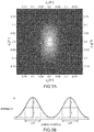
- the carbon nanotube wire preferably includes a plurality of the carbon nanotube aggregates, and a full-width at half maximum ⁇ in azimuth angle in azimuth plot based on small-angle X-ray scattering indicating an orientation of the plurality of carbon nanotube aggregates is preferably equal to or less than 80°, and a thickness deviation rate of the insulating coating layer is preferably equal to or greater than 80%.
- the full-width at half maximum ⁇ in azimuth angle is preferably equal to or less than 60°.
- a proportion of a sectional area of the insulating coating layer in a radial direction with respect to a sectional area of the carbon nanotube wire in the radial direction is preferably equal to or greater than 0.01 and equal to or less than 1.5.
- the sectional area of the carbon nanotube wire in the radial direction is preferably equal to or greater than 0.0005 mm 2 and equal to or less than 80 mm 2 .
- the proportion of the Young's modulus of the material configuring the insulating coating layer with respect to the Young's modulus of the carbon nanotube wire is preferably equal to or greater than 0.0005 and equal to or less than 0.1.
- the carbon nanotube wire preferably includes a plurality of the carbon nanotube aggregates, and a full-width at half maximum ⁇ in azimuth angle in azimuth plot based on small-angle X-ray scattering indicating an orientation of the plurality of carbon nanotube aggregates is preferably equal to or greater than 40°.
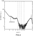
- a q value of a peak top at a (10) peak of scattering intensity based on X-ray scattering indicating density of the plurality of carbon nanotubes is preferably equal to or greater than 2.0 nm -1 and equal to or less than 5.0 nm -1
- a full-width at half maximum ⁇ q is preferably equal to or greater than 0.1 nm -1 and equal to or less than 2.0 nm -1 .
- a carbon nanotube wire using carbon nanotubes as a core wire has anisotropic heat conduction, and heat is transmitted with priority in a longitudinal direction than in a radial direction, unlike a core wire made of metal.
- the carbon nanotube wire since the carbon nanotube wire has anisotropic heat dissipation ability, the carbon nanotube wire has more excellent heat dissipation ability as compared with the core wire made of metal. Therefore, it is necessary to employ design of an insulating coating layer coating the core wire using the carbon nanotubes, which is different from design of an insulating coating layer for the core wire made of metal.
- the thickness deviation rate of the insulating coating layer being equal to or greater than 80%, more uniform insulating coating layer is formed, the coated carbon nanotube electric wire is unlikely to be bent in the longitudinal direction, and it is possible to easily arrange the coated carbon nanotube electric wire when an electric wire path is formed in equipment or a device and thereby to achieve both excellent insulation property and excellent handling ability.
- the proportion of the sectional area of the insulating coating layer in the radial direction with respect to the sectional area of the carbon nanotube wire in the radial direction being equal to or greater than 0.01 and equal to or less than 1.5, it is possible to realize excellent abrasion resistance without degrading an insulating property and also to realize further weight reduction even in a case in which an insulating coating layer with a thin thickness that is likely to deviate is formed.
- the proportion of the Young's modulus of the material configuring the insulating coating layer with respect to the Young's modulus of the carbon nanotube wire being equal to or greater than 0.00001 and equal to or less than 0.5, it is possible to reliably prevent occurrence of peeling of the insulating coating layer from the carbon nanotube wire and cracking in the insulating coating layer even if the coated carbon nanotube electric wire is repeatedly bent.
- the carbon nanotube aggregates have a high orientation in the carbon nanotube wire, and heat dissipation ability of the carbon nanotube wire is thus further improved.
- the q value of the peak top at the (10) peak of scattering intensity based on X-ray scattering of aligned carbon nanotubes being equal to or greater than 2.0 nm -1 and equal to or less than 5.0 nm -1
- the full-width at half maximum ⁇ q being equal to or greater than 0.1 nm -1 and equal to or less than 2.0 nm -1
- heat dissipation ability of the carbon nanotube wire is further improved since the carbon nanotubes can be present with high density.
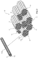
- the CNT wire 10 is an element wire (solid wire) made of one CNT wire 10 in FIG. 1
- the CNT wire 10 may be in a state of twisted wire in which a plurality of CNT wires 10 are twisted. It is possible to appropriately adjust an equivalent circle diameter and a sectional area of the CNT wire 10 by employing a form of the twisted wire for the CNT wire 10.
- the Young's modulus of the CNT wire 10 is 300 to 1500 GPa, for example. Also, the Young's modulus of the CNT wire 10 is 600 to 1500 GPa, for example, in a case in which the CNT wire 10 is an element wire (solid wire) while the Young's modulus of the CNT wire 10 is 300 to 1200 GPa, for example, in a case in which the CNT wire 10 is a twisted wire.
- the CNT aggregates 11 are bundles of CNTs 11a that have a layer structure of one or more layers.
- the longitudinal direction of the CNTs 11a forms a longitudinal direction of the CNT aggregates 11.
- the plurality of CNTs 11a, 11a, ... in the CNT aggregates 11 are disposed such that the long axis directions thereof are substantially aligned. Therefore, the plurality of CNTs 11a, 11a, ... in the CNT aggregates 11 are oriented.
- the equivalent circle diameter of the CNT aggregates 11 is equal to or greater than 20 nm and equal to or less than 1000 nm, for example, and is more typically equal to or greater than 20 nm and equal to or less than 80 nm.
- the width dimension of the outermost layer of the CNTs 11a is equal to or greater than 1.0 nm and equal to or less than 5.0 nm, for example.
- a CNT with a small number of layers such as a two-layer structure or a three-layer structure
- the proportion of the CNTs with a two-layer structure or a three-layer structure with respect to all the CNTs is preferably equal to or greater than 50% by number and is more preferably equal to or greater than 75% by number.
- the full-width at half maximum ⁇ in azimuth angle is equal to or less than 80°, it is considered that the plurality of CNTs 11a, 11a, ... and the plurality of CNT aggregates 11, 11, ... have orientations to some extent in the CNT wire 10.
- an upper limit value of the full-width at half maximum ⁇ in azimuth angle is not particularly limited, the upper limit value is preferably 80°, is more preferably 60°, and is further preferably 50° in order to enhance orientations of the CNTs 11a and the CNT aggregates 11 and to further improve heat dissipation ability of the CNT wire 10.
- a lower limit value of the full-width at half maximum ⁇ in azimuth angle is not particularly limited, the lower limit value is preferably 40° in order to improve heat dissipation ability.
- FIG. 4 is a graph illustrating a relationship of a q value-intensity in wide-angle X-ray scattering (WAXS) of the plurality of CNTs 11a, 11a, ... configuring the CNT aggregates 11.
- WAXS wide-angle X-ray scattering
- the plurality of CNT aggregates 11, 11, ... have satisfactory orientations and further the plurality of CNTs 11a, 11a, ... that configure the CNT aggregates 11 are aligned with regularity and are disposed with high density as described above, the heat from the CNT wire 10 is likely to be discharged while smoothly delivered along the longitudinal direction of the CNT aggregates 11. Therefore, since it is possible to adjust the heat dissipation route in the longitudinal direction and the radial sectional direction by adjusting the alignment structures and the density of the CNT aggregates 11 and the CNTs 11a, the CNT wire 10 exhibits more excellent heat dissipation ability as compared with the core wire made of metal.
- the q value of the peak top at the (10) peak of the intensity based on the X-ray scattering indicating density of the plurality of CNTs 11a, 11a, ... is preferably equal to or greater than 2.0 nm -1 and equal to or less than 5.0 nm -1
- the full-width at half maximum ⁇ q (FWHM) is preferably equal to or greater than 0.1 nm -1 and equal to or less than 2.0 nm -1 in order to further improve heat dissipation ability by obtaining high density.
- thermoplastic resin examples include polytetrafluoroethylene (PTFE) (Young's modulus: 0.4 GPa), polyethylene (Young's modulus: 0.1 to 1.0 GPa), polypropylene (Young's modulus: 1.1 to 1.4 GPa), polyacetal (Young's modulus: 2.8 GPa), polystyrene (Young's modulus: 2.8 to 3.5 GPa), polycarbonate (Young's modulus: 2.5 GPa), polyamide (Young's modulus: 1.1 to 2.9 GPa), polyvinyl chloride (Young's modulus: 2.5 to 4.2 GPa), polymethyl methacrylate (Young's modulus: 3.2 GPa), polyurethane (YoungFE) (Young's modulus: 0.4 GPa), polyethylene (Young's modulus: 0.1 to 1.0 GPa), polypropylene (Young's modulus: 1.1 to 1.4 GPa), polyacetal
- the proportion of the sectional area of the insulating coating layer 21 in the radial direction with respect to the sectional area of the CNT wire 10 in the radial direction is preferably within a range of equal to or greater than 0.01 and equal to or less than 1.5.
- the CNT wire 10 has a lighter weight than a core wire made of copper, aluminum, or the like, it is possible to reduce the thickness of the insulating coating layer 21, and it is thus possible to sufficiently secure insulation reliability and to obtain excellent heat dissipation ability with respect to the heat of the CNT wire 10.
- the coated CNT electric wire 1 can maintain the shape in the longitudinal direction since the peripheral surface of the CNT wire 10 is coated with the insulating coating layer 21 at the aforementioned proportion of the sectional area. Therefore, it is possible to enhance handling ability when the coated CNT electric wire 1 is arranged.
- the proportion of the sectional areas is not particularly limited, the proportion is preferably equal to or greater than 0.01 and equal to or less than 1.5, and a lower limit value thereof is preferably 0.2 and is particularly preferably 0.5 in order to further improve insulation reliability.
- an upper limit value of the proportion of the sectional areas is preferably 1.0 and is particularly preferably 0.8 in order to further reduce the weight of the coated CNT electric wire 1 and to further improve heat dissipation ability with respect to the heat of the CNT wire 10.
- sectional area of the insulating coating layer 21 in the radial direction is not particularly limited, the sectional area is preferably equal to or greater than 0.002 mm 2 and equal to or less than 40 mm 2 and is particularly preferably equal to or greater than 0.02 mm 2 and equal to or less than 2 mm 2 , for example, in terms of a balance between insulation reliability and heat dissipation ability.
- the sectional areas can be measured from a scanning electron microscope (SEM) observation image, for example. Specifically, an SEM image (100 times to 10,000 times) of a section of the coated CNT electric wire 1 in the radial direction is obtained, then an area obtained by subtracting an area of the material of the insulating coating layer 21 that has entered the inside of the CNT wire 10 from an area of a portion surrounded by the outer periphery of the CNT wire 10 and a total of an area of the portion of the insulating coating layer 21 coating the outer periphery of the CNT wire 10 and an area of the material of the insulating coating layer 21 that has entered the inside of the CNT wire 10 are defined as a sectional area of the CNT wire 10 in the radial direction and a sectional area of the insulating coating layer 21 in the radial direction, respectively.
- the sectional area of the insulating coating layer 21 in the radial direction includes a resin that has entered the interspace of the CNT wire 10.
- the Young's modulus of the CNTs is higher than the Young's modulus of aluminum or copper used in a core wire in the related art. While the Young's modulus of aluminum is 70.3 GPa and the Young's modulus of copper is 129.8 GPa, the Young's modulus of the CNTs is 300 to 1500 GPa, which is a value of more than about double to about ten times.
- the coated CNT electric wire 1 since it is possible to use a material with a high Young's modulus (for example, a thermoplastic resin with a high Young's modulus) as the material of the insulating coating layer 21 in the coated CNT electric wire 1 as compared with the coated electric wire using aluminum or copper in the core wire and thereby to provide excellent abrasion resistance to the insulating coating layer 21 of the coated CNT electric wire 1, and the coated CNT electric wire 1 exhibits excellent durability.
- a material with a high Young's modulus for example, a thermoplastic resin with a high Young's modulus
- the proportion of the Young's modulus of the material configuring the insulating coating layer with respect to the Young's modulus of the core wire in the coated CNT electric wire 1 is smaller than the proportion of the Young's modulus of the coated electric wire using aluminum or copper in the core wire. Therefore, it is possible to curb peeling-off between the CNT wire 10 and the insulating coating layer 21 and cracking of the insulating coating layer 21 even if the coated CNT electric wire 1 is repeatedly bent, as compared with the coated electric wire using aluminum or copper in the core wire.
- a lower limit value of the proportion of the Young's moduli is preferably 0.00001 in order to prevent the insulating coating layer 21 from peeling off from the CNT wire 10 due to the insulating coating layer 21 following the CNT wire 10 even if the coated CNT electric wire 1 is repeatedly bent, and is more preferably 0.0005 and is particularly preferably 0.001 in order to prevent the insulating coating layer 21 from peeling off from the CNT wire 10 even if the coated CNT electric wire 1 is bent over a long period of time.
- an upper limit value of the proportion of the Young's modulus is preferably 0.5 in order to prevent cracking from occurring in the insulating coating layer 21 even if the coated CNT electric wire 1 is repeatedly bent, and is more preferably 0.1, is further preferably 0.01, and is particularly preferably 0.005 in order to prevent cracking from occurring in the insulating coating layer 21 even if the coated CNT electric wire 1 is bent over a long period of time.
- the thickness of the insulating coating layer 21 in a direction that perpendicularly intersects the longitudinal direction (that is, the radial direction) is preferably uniformized in order to improve an insulation property and abrasion resistance of the coated CNT electric wire 1.
- the thickness deviation rate of the insulating coating layer 21 is equal to or greater than 50% in order to improve an insulation property and abrasion resistance and is preferably equal to or greater than 80% in order to improve handling ability in addition to the insulation property and the abrasion resistance.
- the thickness of the insulating coating layer 21 can be measured from an image of SEM observation by circularly approximating the CNT wire 10, for example.
- the center side in the longitudinal direction indicates a region located at the center when seen in the longitudinal direction of the wire.
- the thickness deviation rate of the insulating coating layer 21 can be improved by adjusting a tensile force applied to the CNT wires 10 in the longitudinal direction when the CNT wire 10 is caused to pass through a die in an extrusion process in a case in which the insulating coating layer 21 is formed at the peripheral surface of the CNT wire 10 through extrusion coating, for example.
- the tensile force to be applied to the CNT wire 10 is preferably set to be large such that the die and the CNT wire 10 maintain a successively coaxial or substantially coaxial state, for example.
- the thickness deviation rate of the insulating coating layer 21 can be improved by increasing circularity of the section of the wire in the radial direction for a solid wire or by increasing the number of twists for a twisted wire.
- the number of twists in the case in which the CNT wire 10 is formed as a twisted wire is not particularly limited, the number of twists is preferably equal to or greater than 40 T/m and equal to or less than 1500 T/m.
- a lower limit value of the number of twists is more preferably 100 and is further preferably 200 in order to obtain sufficient strength of the wire.
- an upper limit value of the number of twists is more preferably 1000 and is further preferably 800 in order to curb variations in the CNT wire 10 due to a stress caused by twisting-back.
- the number of twists is less than 40 T/m, tensile strength of the CNT wire 10 is insufficient, it is not possible to apply a sufficient tensile force to the CNT wire 10 in the insulating coating processing, and variations in the CNT wire 10 passing through the die are likely to occur. Therefore, the thickness deviation rate of the insulating coating layer is likely to be low.
- the number of twists exceeds 1500 T/m, the tensile strength of the CNT wire 10 is high, and it is thus possible to apply a sufficient tensile force to the CNT wire 10 in the insulating coating processing.
- the thickness deviation rate of the insulating coating layer is likely to be low. If the number of twists is equal to or greater than 40 T/m and equal to or less than 1500 T/m, the thickness deviation rate of the insulating coating layer is high, and an excellent insulation property is achieved. Also, if the number of twists is equal to or greater than 200 T/m and equal to or less than 1000 T/m, the thickness deviation rate of the insulating coating layer is likely to be high, and a further excellent insulation property is achieved.
- the number of twists of the CNT wire 10 is equal to or greater than 40 T/m and equal to or less than 1500 T/m and is preferably equal to or greater than 200 T/m and equal to or less than 1000 T/m, and is further, the full-width at half maximum ⁇ in azimuth angle of the CNT wire is preferably equal to or less than 80°, and the thickness deviation rate of the insulating coating layer is preferably equal to or greater than 80%. If the number of twists of the CNT wire 10 is equal to or greater than 40 T/m an equal to or less than 1500 T/m, the CNTs are disposed with high density.
- the CNT aggregates 11 have a high orientation in the CNT wire 10.
- the heat of the CNT wire 10 is likely to be delivered along the longitudinal direction, and the CNT wire 10 exhibits excellent heat dissipation ability.
- the thickness deviation rate of the insulating coating layer being equal to or greater than 80%, insulation breakage is unlikely to occur, and an excellent insulation property is achieved.
- the coated CNT electric wire 1 can be manufactured by manufacturing the CNTs 11a first, forming the CNT wire 10 from the plurality of obtained CNTs 11a, and coating the peripheral surface of the CNT wire 10 with the insulating coating layer 21.
- the CNTs 11a can be produced by a method such as a floating catalyst method (Japanese Patent No. 5819888 ) or a substrate method (Japanese Patent No. 5590603 ).
- the strands of the CNT wire 10 can be produced by, for example, dry spinning (Japanese Patent No. 5819888 , Japanese Patent No. 5990202 , and Japanese Patent No. 5350635 ), wet spinning (Japanese Patent No. 5135620 , Japanese Patent No. 5131571 , and Japanese Patent No. 5288359 ), liquid crystal spinning (National Publication of International Patent Application No. 2014-530964 ), or the like.
- the orientation of the CNT aggregates 11 configuring the CNT wire 10 or the orientation of the CNTs 11a configuring the CNT aggregates 11 can be adjusted by appropriately selecting a spinning method such as dry spinning, wet spinning, or liquid crystal spinning, for example, and spinning conditions for the spinning method.
- a spinning method such as dry spinning, wet spinning, or liquid crystal spinning, for example, and spinning conditions for the spinning method.
- a twisted wire In a case of a twisted wire, it is possible to obtain the twisted wire by bundling a plurality of solid wires and twisting ends on one side a plurality of number of times in a state in which ends on the other side are fixed.
- the number of twists can be represented by a value (unit: T/m) obtained by dividing the number of times (T) the wires are twisted by the length (m) of the wires.
- a method for coating a core wire made of aluminum or copper with the insulating coating layer can be used, and for example, it is possible to exemplify a method of melting a thermoplastic resin that is a raw material of the insulating coating layer 21 and extruding the thermoplastic resin to the circumference of the CNT wire 10 to coat the CNT wire 10 with the thermoplastic resin or a method of applying a molten thermoplastic resin to the circumference of the CNT wire 10.
- the coated CNT electric wire 1 according to the embodiment of the present invention can be used as a general electric wire such as a wire harness, or a cable may be produced from the general electric wire using the coated CNT electric wire 1.
- a coil may be produced by winding the coated CNT electric wire 1.
- space factor is preferably equal to or greater than 60%.
- the coil can be used for various motors and the like and is particularly preferably used for a precision device, a medical device, a portable device, or the like in terms of heat dissipation ability and light weight.
- strands (solidwires) of CNT wires with equivalent circle diameters of 0.2 mm were obtained by a dry spinning method (Japanese Patent No. 5819888 ) of directly spinning CNTs produced by the floating catalyst method or a method of wet-spinning the CNTs (Japanese Patent No. 5135620 , Japanese Patent No. 5131571 , and Japanese Patent No. 5288359 ). Also, CNT wires with equivalent circle diameters of greater than 0.2 mm were obtained by adjusting the number of CNT wires with an equivalent circle diameter of 0.2 mm and appropriately twisting the CNT wires together, thereby obtaining twisted wires.
- Insulating coating layers were formed by extruding any of the following resins to the circumferences of conductive elements and coating the circumferences with the resins using an ordinary extruding and molding machine for manufacturing an electric wire, thereby producing coated CNT electric wires used in examples and comparative examples in Table 1 shown below. Also, thickness deviation rates were adjusted by changing a tensile force to be applied to the CNT wires.
- a section of each CNT wire in the radial direction was cut using an ion milling device (IM4000 manufactured by Hitachi High-Tech Corporation), and the sectional area of each CNT wire in the radial direction was then measured from an SEM image obtained by a scanning electron microscope (SU8020 manufactured by Hitachi High-Tech Corporation, magnification: 100 times to 10,000 times). Similar measurement was repeated at every 10 cm from arbitrary 1.0 m of the coated CNT electric wire on the center side in the longitudinal direction, and an average value thereof was defined as a sectional area of the CNT wire in the radial direction. Note that the resin that entered the inside of the CNT wire was not included in the sectional area of the CNT wire.
- a section of each CNT wire in the radial direction was cut using an ion milling device (IM4000 manufactured by Hitachi High-Tech Corporation), and the sectional area of the insulating coating layer in the radial direction was then measured from an SEM image obtained by a scanning electron microscope (SU8020 manufactured by Hitachi High-Tech Corporation, magnification: 100 times to 10,000 times). Similar measurement was repeated at every 10 cm from arbitrary 1.0 m of the coated CNT electric wire on the center side in the longitudinal direction, and an average value thereof was defined as a sectional area of the insulating coating layer in the radial direction. Therefore, the resin that entered the inside of the CNT wire was included as a sectional area of the insulating coating layer in the measurement.
- IM4000 manufactured by Hitachi High-Tech Corporation
- the CNT wires were obtained as twisted wires by bundling a plurality of strands and twisting ends on one side a predetermined number of times in a state in which ends on the other side were fixed. Each number of twists was represented by a value obtained by dividing the number of times (T) the wires were twisted by the length (m) of the wires.
- Small-angle X-ray scattering measurement was performed using a small-angle X-ray scattering device (Aichi Synchrotron), and full-widths at half maximum ⁇ in azimuth angle were obtained from the obtained azimuth plots.
- Wide-angle X-ray scattering measurement was performed using a wide-angle X-ray scattering device (Aichi Synchrotron), and q values of the peak tops at (10) peaks of intensity and full-widths at half maximum ⁇ q were obtained from obtained q-value-intensity graphs.
- the insulating coating layer was made to peel from each 1.0 m coated CNT electric wire.
- Five 5 cm test pieces were collected at every 20 cm in the longitudinal direction from each of the peeled insulating coating layer and the CNT wire.
- a tensile test was conducted by a method in accordance with JIS K 7161-1, and the Young's modulus of each test piece was obtained.
- a proportion of the Young's modulus of the material configuring the insulating coating layer with respect to the Young's modulus of the CNT wire was calculated on the basis of a value obtained by averaging the Young's moduli of the five test pieces of each insulating coating layer and a value obtained by averaging the Young's moduli of the five test pieces of each CNT wire.
- each 1.0 m coated CNT electric wire was cut at every 10 cm in the longitudinal direction, and thicknesses of the insulating coating layer at the sections in the radial direction were measured.
- a value of ⁇ (a minimum value of the thickness of the insulating coating layer/a maximum value of the thickness of the insulating coating layer) ⁇ 100 was calculated.
- a value obtained by averaging the ⁇ values calculated in the sections was defined as each thickness deviation rate.
- the thickness of the insulating coating layer was able to be measured from an SEM image as a shortest distance from an interference of a circularly approximated CNT wire 10 and the insulating coating layer 21, for example.
- coated CNT electric wires produced as described above were evaluated as follows.
- a rate of increase in resistance of less than 5% was evaluated as being satisfactory "O"
- a rate of increase in resistance of equal to or greater than 5% and less than 10% was evaluated as being substantially satisfactory
- a rate of increase in resistance of equal to or greater than 10% was evaluated as being inferior " ⁇ ".
- a 100 cm coated CNT electric wire was bent at 90 degrees 1000 times in a state in which a load of 500 gf was applied thereto. Thereafter, section observation was performed at every 10 cm of the coated CNT electric wire in the longitudinal direction, and whether or not there was peeling between the coated CNT electric wire and the insulating coating layer was checked.
- a coated CNT electric wire with no peeling was evaluated as being satisfactory "O”
- a coated CNT electric wire that partially peeled in an allowable level of product quality was evaluated as being substantially satisfactory " ⁇ ”
- a coated CNT electric wire with the CNT wire disconnected was evaluated as being inferior " ⁇ ".
- a test for evaluating abrasion resistance was conducted by a method in accordance with JIS C 3216-3, Article 6.
- a test result that satisfied the grade 2 described in Table 1 in JIS C 3215-4 was evaluated as being satisfactory "O”
- a test result that satisfied the grade 1 was evaluated as being satisfactory " ⁇ ”
- a test result that did not satisfy any grade was evaluated as being inferior " ⁇ ”
- test results evaluated as " ⁇ " or higher were evaluated as indicating excellent abrasion resistance.
- An insulation breakage test for evaluating insulation reliability was conducted by a method in accordance with JIS C 3216-5, Article 4.
- a test result that satisfied the grade 3 described in Table 9 in JIS C 3215-0-1 was evaluated as being significantly satisfactory " ⁇ ”
- a test result that satisfied the grade 2 was evaluated as being satisfactory " ⁇ ”
- a test result that satisfied the grade 1 was evaluated as being substantially satisfactory " ⁇ ”
- a test result that did not satisfy any grades was evaluated as being inferior " ⁇ ”.
- a five-layer coil with a width of 10 mm was obtained by manually winding the coated CNT electric wire around a core with a diameter of 10 mm at a constant speed.
- space factor (space factor (%) (a sum of sectional areas of the coated CNT electric wire)/(coil sectional area) ⁇ 100) was obtained. Coils were produced five times for each coated CNT electric wire, and an average value of the coils produced five times was defined as the space factor.
- Space facto of equal to or greater than 70% was evaluated as indicating significantly satisfactory handling ability " ⁇ ”
- space factor of equal to or greater than 50% and less than 70% was evaluated as indicating satisfactory handling ability " ⁇ ”
- space factor of less than 50% was evaluated as indicating not satisfactory handling ability " ⁇ ".
- the thickness deviation rates of the insulating coating layers in the coated CNT electric wires were equal to or greater than 50%, and all heat dissipation abilities, durability in bending, abrasion resistance, and insulation reliability were satisfactory.
- the thickness deviation rates of the insulating coating layers in the coated CNT electric wires were equal to or greater than 60% and equal to or less than 79%, and abrasion resistance and insulation reliability were more satisfactory.
- the coated CNT electric wires in which the thickness deviation rates of the insulating coating layers were equal to or greater than 80% Examples 4, 5, 9, 10, 17, 19, and 20
- excellent abrasion resistance and insulation reliability were achieved.
- Example 6 in particular, excellent heat dissipation ability was achieved since the full width at half maximum ⁇ in azimuth angle was as small as 55°. Also, in Examples 1 to 5 and 8 to 20, heat dissipation ability was more satisfactory since the full-widths at half maximum ⁇ in azimuth angle was 40°, which was yet smaller.
- Comparative Example 1 the thickness deviation rate of the insulating coating layer was 42%, and both abrasion resistance and insulation reliability were inferior.
- Comparative Example 2 the thickness deviation rate of the insulating coating layer was 38%, and winding was not stably performed at the time of working into a coil form. Due to poor handling ability, space factor of the coil decreased.
- Comparative Example 3 the thickness deviation rate of the insulating coating layer was 41%, and both abrasion resistance and insulation reliability were inferior.
- conductive elements were copper wires or aluminum wires, and durability in bending was inferior.
Landscapes
- Chemical & Material Sciences (AREA)
- Engineering & Computer Science (AREA)
- Organic Chemistry (AREA)
- Materials Engineering (AREA)
- Nanotechnology (AREA)
- Power Engineering (AREA)
- Chemical Kinetics & Catalysis (AREA)
- General Chemical & Material Sciences (AREA)
- Textile Engineering (AREA)
- Inorganic Chemistry (AREA)
- Carbon And Carbon Compounds (AREA)
- Insulated Conductors (AREA)
- Conductive Materials (AREA)
- Non-Insulated Conductors (AREA)
Applications Claiming Priority (2)
| Application Number | Priority Date | Filing Date | Title |
|---|---|---|---|
| JP2017207664 | 2017-10-26 | ||
| PCT/JP2018/039978 WO2019083036A1 (ja) | 2017-10-26 | 2018-10-26 | カーボンナノチューブ被覆電線及びコイル |
Publications (2)
| Publication Number | Publication Date |
|---|---|
| EP3703084A1 true EP3703084A1 (de) | 2020-09-02 |
| EP3703084A4 EP3703084A4 (de) | 2021-08-04 |
Family
ID=66247926
Family Applications (1)
| Application Number | Title | Priority Date | Filing Date |
|---|---|---|---|
| EP18870309.4A Withdrawn EP3703084A4 (de) | 2017-10-26 | 2018-10-26 | Kohlenstoffnanoröhrchenbeschichteter elektrischer draht und spule |
Country Status (5)
| Country | Link |
|---|---|
| US (1) | US20200265968A1 (de) |
| EP (1) | EP3703084A4 (de) |
| JP (1) | JP7306996B2 (de) |
| CN (1) | CN111295722B (de) |
| WO (1) | WO2019083036A1 (de) |
Cited By (1)
| Publication number | Priority date | Publication date | Assignee | Title |
|---|---|---|---|---|
| CN111937088A (zh) * | 2018-03-30 | 2020-11-13 | 古河电气工业株式会社 | 线圈用碳纳米管被覆线材、利用线圈用碳纳米管被覆线材的线圈以及碳纳米管被覆线材线圈的制造方法 |
Families Citing this family (5)
| Publication number | Priority date | Publication date | Assignee | Title |
|---|---|---|---|---|
| DE102019206107A1 (de) * | 2019-04-29 | 2020-10-29 | Robert Bosch Gmbh | Stator einer elektrischen Maschine |
| JP7311374B2 (ja) * | 2019-09-20 | 2023-07-19 | トクセン工業株式会社 | 絶縁被覆カーボンナノチューブ線 |
| US20220255384A1 (en) * | 2021-02-08 | 2022-08-11 | Honeywell International Inc. | Low losses damper bar for electric machines |
| JP7763126B2 (ja) * | 2021-04-15 | 2025-10-31 | 古河電気工業株式会社 | コイル |
| US12549047B2 (en) * | 2023-11-10 | 2026-02-10 | GM Global Technology Operations LLC | Skin effect enhanced high conductive composite stator winding bundles in e-motors |
Family Cites Families (16)
| Publication number | Priority date | Publication date | Assignee | Title |
|---|---|---|---|---|
| JPS5131571B2 (de) | 1971-11-01 | 1976-09-07 | ||
| JPS5135620B2 (de) | 1973-04-04 | 1976-10-04 | ||
| JPS5819888B2 (ja) | 1977-08-12 | 1983-04-20 | 本田技研工業株式会社 | デイスクブレ−キ装置 |
| JP3978653B2 (ja) * | 2002-04-09 | 2007-09-19 | 東洋紡績株式会社 | 細径電線コード |
| JP2006120730A (ja) | 2004-10-19 | 2006-05-11 | Fujitsu Ltd | 層間配線に多層カーボンナノチューブを用いる配線構造及びその製造方法 |
| EP1814713A4 (de) | 2004-11-09 | 2017-07-26 | Board of Regents, The University of Texas System | Herstellung und anwendung von nanofaserbändern und folien sowie gedrehten und nichtgedrehten nanofasergarnen |
| JP5968621B2 (ja) | 2008-05-07 | 2016-08-10 | ナノコンプ テクノロジーズ インコーポレイテッド | ナノ構造体ベースの加熱装置およびその使用方法 |
| JP5590603B2 (ja) | 2010-04-09 | 2014-09-17 | 日本ゼオン株式会社 | カーボンナノチューブ配向集合体の製造装置 |
| CN102314964B (zh) * | 2010-07-05 | 2014-04-23 | 清华大学 | 起搏器 |
| JP5135620B2 (ja) | 2010-11-22 | 2013-02-06 | 古河電気工業株式会社 | 凝集紡糸構造体および電線 |
| US20140084219A1 (en) | 2011-02-28 | 2014-03-27 | William Marsh Rice University | Doped multiwalled carbon nanotube fibers and methods of making the same |
| GB201116670D0 (en) * | 2011-09-27 | 2011-11-09 | Cambridge Entpr Ltd | Materials and methods for insulation of conducting fibres, and insulated products |
| CN103429687B (zh) * | 2011-11-16 | 2017-02-15 | 住友电气工业株式会社 | 绝缘清漆以及使用了该绝缘清漆的绝缘电线 |
| JP5497237B1 (ja) * | 2013-10-17 | 2014-05-21 | 株式会社 Mgコーポレーション | 導電線、導電線の製造方法およびコイル |
| CN105097065B (zh) * | 2014-04-23 | 2018-03-02 | 北京富纳特创新科技有限公司 | 碳纳米管复合导线 |
| WO2019083030A1 (ja) * | 2017-10-26 | 2019-05-02 | 古河電気工業株式会社 | カーボンナノチューブ被覆電線およびその施工方法、識別マークの検出方法 |
-
2018
- 2018-10-26 EP EP18870309.4A patent/EP3703084A4/de not_active Withdrawn
- 2018-10-26 CN CN201880070208.7A patent/CN111295722B/zh active Active
- 2018-10-26 WO PCT/JP2018/039978 patent/WO2019083036A1/ja not_active Ceased
- 2018-10-26 JP JP2019550347A patent/JP7306996B2/ja active Active
-
2020
- 2020-04-24 US US16/858,289 patent/US20200265968A1/en not_active Abandoned
Cited By (4)
| Publication number | Priority date | Publication date | Assignee | Title |
|---|---|---|---|---|
| CN111937088A (zh) * | 2018-03-30 | 2020-11-13 | 古河电气工业株式会社 | 线圈用碳纳米管被覆线材、利用线圈用碳纳米管被覆线材的线圈以及碳纳米管被覆线材线圈的制造方法 |
| EP3780007A4 (de) * | 2018-03-30 | 2022-01-12 | Furukawa Electric Co., Ltd. | Mit kohlenstoff-nanoröhren beschichteter walzdraht für spule, spule mit dem mit kohlenstoff-nanoröhren beschichteten walzdraht für eine spule und verfahren zur herstellung einer spule aus mit kohlenstoff-nanoröhren beschichtetem walzdraht |
| CN111937088B (zh) * | 2018-03-30 | 2023-01-31 | 古河电气工业株式会社 | 线圈用碳纳米管被覆线材、利用线圈用碳纳米管被覆线材的线圈以及碳纳米管被覆线材线圈的制造方法 |
| US11664135B2 (en) | 2018-03-30 | 2023-05-30 | Furukawa Electric Co., Ltd. | Coated carbon nanotube wire for coil, coil using coated carbon nanotube wire for coil, and method for manufacturing coated carbon nanotube wire coil |
Also Published As
| Publication number | Publication date |
|---|---|
| EP3703084A4 (de) | 2021-08-04 |
| US20200265968A1 (en) | 2020-08-20 |
| JP7306996B2 (ja) | 2023-07-11 |
| WO2019083036A1 (ja) | 2019-05-02 |
| CN111295722B (zh) | 2022-11-01 |
| CN111295722A (zh) | 2020-06-16 |
| JPWO2019083036A1 (ja) | 2020-12-24 |
Similar Documents
| Publication | Publication Date | Title |
|---|---|---|
| EP3703084A1 (de) | Kohlenstoffnanoröhrchenbeschichteter elektrischer draht und spule | |
| US20200258648A1 (en) | Carbon nanotube strand wire, coated carbon nanotube electric wire, and wire harness | |
| WO2019083029A1 (ja) | カーボンナノチューブ被覆電線 | |
| JP2019079813A (ja) | カーボンナノチューブ被覆電線、コイル及び被覆電線 | |
| US20200258652A1 (en) | Carbon nanotube strand wire, coated carbon nanotube electric wire, wire harness, wiring for robot, and overhead wiring for train | |
| US20200258651A1 (en) | Coated carbon nanotube electric wire | |
| US20200258650A1 (en) | Coated carbon nanotube electric wire | |
| US20200251248A1 (en) | Coated carbon nanotube electric wire | |
| US20200251245A1 (en) | Coated carbon nanotube electric wire | |
| US20200251247A1 (en) | Coated carbon nanotube electric wire | |
| WO2019083033A2 (ja) | カーボンナノチューブ被覆電線 | |
| US20200251240A1 (en) | Carbon nanotube strand wire, coated carbon nanotube electric wire, and wire harness | |
| JP7050719B2 (ja) | カーボンナノチューブ被覆電線 | |
| EP3703081B1 (de) | Beschichteter elektischer draht aus kohlenstoffnanoröhren | |
| US20200258653A1 (en) | Coated carbon nanotube electric wire |
Legal Events
| Date | Code | Title | Description |
|---|---|---|---|
| STAA | Information on the status of an ep patent application or granted ep patent |
Free format text: STATUS: THE INTERNATIONAL PUBLICATION HAS BEEN MADE |
|
| PUAI | Public reference made under article 153(3) epc to a published international application that has entered the european phase |
Free format text: ORIGINAL CODE: 0009012 |
|
| STAA | Information on the status of an ep patent application or granted ep patent |
Free format text: STATUS: REQUEST FOR EXAMINATION WAS MADE |
|
| 17P | Request for examination filed |
Effective date: 20200428 |
|
| AK | Designated contracting states |
Kind code of ref document: A1 Designated state(s): AL AT BE BG CH CY CZ DE DK EE ES FI FR GB GR HR HU IE IS IT LI LT LU LV MC MK MT NL NO PL PT RO RS SE SI SK SM TR |
|
| AX | Request for extension of the european patent |
Extension state: BA ME |
|
| DAV | Request for validation of the european patent (deleted) | ||
| DAX | Request for extension of the european patent (deleted) | ||
| REG | Reference to a national code |
Ref country code: DE Ref legal event code: R079 Free format text: PREVIOUS MAIN CLASS: H01B0007000000 Ipc: H01B0001040000 |
|
| A4 | Supplementary search report drawn up and despatched |
Effective date: 20210701 |
|
| RIC1 | Information provided on ipc code assigned before grant |
Ipc: H01B 1/04 20060101AFI20210625BHEP Ipc: H01B 5/08 20060101ALI20210625BHEP Ipc: C01B 32/158 20170101ALI20210625BHEP Ipc: H01B 7/42 20060101ALI20210625BHEP Ipc: H01B 7/00 20060101ALI20210625BHEP |
|
| STAA | Information on the status of an ep patent application or granted ep patent |
Free format text: STATUS: EXAMINATION IS IN PROGRESS |
|
| 17Q | First examination report despatched |
Effective date: 20221207 |
|
| STAA | Information on the status of an ep patent application or granted ep patent |
Free format text: STATUS: THE APPLICATION HAS BEEN WITHDRAWN |
|
| 18W | Application withdrawn |
Effective date: 20230411 |