EP3703022A1 - Anordnung zum sicheren verschliessen eines kopfmoduls einer vorrichtung zur handhabung von wertscheinen - Google Patents
Anordnung zum sicheren verschliessen eines kopfmoduls einer vorrichtung zur handhabung von wertscheinen Download PDFInfo
- Publication number
- EP3703022A1 EP3703022A1 EP19160182.2A EP19160182A EP3703022A1 EP 3703022 A1 EP3703022 A1 EP 3703022A1 EP 19160182 A EP19160182 A EP 19160182A EP 3703022 A1 EP3703022 A1 EP 3703022A1
- Authority
- EP
- European Patent Office
- Prior art keywords
- unit
- locking
- frame
- head module
- electromechanical
- Prior art date
- Legal status (The legal status is an assumption and is not a legal conclusion. Google has not performed a legal analysis and makes no representation as to the accuracy of the status listed.)
- Granted
Links
Images





Classifications
-
- G—PHYSICS
- G07—CHECKING-DEVICES
- G07F—COIN-FREED OR LIKE APPARATUS
- G07F19/00—Complete banking systems; Coded card-freed arrangements adapted for dispensing or receiving monies or the like and posting such transactions to existing accounts, e.g. automatic teller machines
- G07F19/20—Automatic teller machines [ATMs]
- G07F19/205—Housing aspects of ATMs
-
- G—PHYSICS
- G06—COMPUTING OR CALCULATING; COUNTING
- G06Q—INFORMATION AND COMMUNICATION TECHNOLOGY [ICT] SPECIALLY ADAPTED FOR ADMINISTRATIVE, COMMERCIAL, FINANCIAL, MANAGERIAL OR SUPERVISORY PURPOSES; SYSTEMS OR METHODS SPECIALLY ADAPTED FOR ADMINISTRATIVE, COMMERCIAL, FINANCIAL, MANAGERIAL OR SUPERVISORY PURPOSES, NOT OTHERWISE PROVIDED FOR
- G06Q20/00—Payment architectures, schemes or protocols
- G06Q20/08—Payment architectures
- G06Q20/18—Payment architectures involving self-service terminals [SST], vending machines, kiosks or multimedia terminals
Definitions
- the invention relates to an arrangement for securely closing a head module of a device for handling notes of value.
- the arrangement comprises at least one head module which comprises at least one frame and a front panel. Furthermore, the arrangement comprises at least one sensor unit for outputting a control signal, an authentication unit for determining authentication information and a control unit.
- the head module comprises at least one electromechanical locking unit which, in a locking state, produces a locking of the front panel with the frame, and which cancels the locking in an unlocked state.
- the control unit is designed to carry out a detection of the control signal and a verification of the authentication information. Furthermore, the control unit is designed to control the electromechanical locking unit in such a way that a change in the electromechanical locking unit from the locking state to the unlocking state only occurs when the control signal is detected and if the authentication information is successfully verified. This creates a particularly secure locking of the front panel with the frame that is protected against manipulation.
- the arrangement comprises at least one mechanically actuable locking element, the front panel being pivotable relative to the frame or removable from the frame or horizontally and / or vertically by means of telescopic rails only when the at least one mechanically actuable locking element and the at least one electromechanical locking unit are unlocked is displaceable relative to the frame. It is thus achieved that manipulation, in particular breaking open the front panel, is made considerably more difficult.
- At least one rod-shaped locking element is arranged at a fixed position in the head module and is in engagement with the mechanically actuatable locking element in the locked state. This prevents the front panel from pivoting about a pivot axis or from removing the front panel or from horizontally and / or vertically shifting the front panel relative to the frame.
- control unit is designed to authorize a user to open the front panel on the basis of the authentication information to investigate. This ensures that the front panel remains in the locked state if the authentication fails.
- the sensor unit comprises a lock and an electrical switch, the electrical switch being designed and arranged such that it generates the control signal when the lock is operated with the aid of a key. A particularly simple and reliable generation of the control signal is thereby achieved.
- the electromechanical locking unit has a manually operated emergency release which can be operated with the aid of a mechanical operating element, the mechanical operating element preferably comprising an operating wire or an operating cable, one end of which is coupled to the electromechanical locking unit and the other end of which is connected to another Module of the device for handling notes of value, preferably in a safe module, the mechanical actuating element in the further module is only accessible to an authorized user via an opening in the further module. This ensures that the emergency release cannot be actuated by the unauthorized third party in the event of unauthorized access to the head module.
- the sensor unit is designed to detect the opening of a door of the head module and, based on the detection of the opening of the door, output the control signal and transmit it to the control unit.
- the electromechanical locking unit has a manually operated emergency release which can be operated with the aid of an unlocking tool, the emergency release being only possible when the door of the head module is open. This effectively counteracts an emergency release by unauthorized third parties.
- the head module comprises a first electromechanical locking unit firmly connected to the front panel or to the frame and a second electromechanical locking unit firmly connected to the front panel or to the frame, the second electromechanical locking unit on a side of the frame opposite the first electromechanical locking unit or the front panel is arranged.
- the mechanically actuatable locking unit comprises a switch for outputting a switching signal if the control unit is designed is to detect the switching signal, and if the control unit is designed to control the electromechanical locking unit in such a way that the electromechanical locking unit is changed from the unlocked state to the locked state when the switching signal is detected and the authentication information is verified.
- a particularly compact, safe and simple structure of the arrangement is achieved in this way.
- the frame of the head module is integrated in a housing of the head module or if the frame of the head module is surrounded by the housing of the head module. This creates a particularly stable connection between the frame and the head module.
- a note handling unit arranged in the head module is locked in the locked state with the frame with the aid of a further electromechanical locking unit, and if the control unit is designed to control the further electromechanical locking unit in such a way that a change in the further electromechanical locking unit from the locking state to the unlocking state only takes place upon detection of the control signal and upon successful verification of the authentication information. This makes it particularly difficult for an unauthorized third party to detach the value note handling unit from the head module.
- the further electromechanical locking unit is moved from the locking state to the unlocking state only when further authentication information is available from the user. A particularly high degree of security against displacement or removal of the value note handling unit is thereby achieved.
- Figure 1 shows a front view of a device 10 for handling notes of value according to a first embodiment. To better explain the exemplary embodiment individual elements of the device 10 are not shown.
- the device 10 comprises a head module 100 and a safe module 200.
- a plurality of money cassettes (not shown) for receiving notes of value can be accommodated in the safe module 200.
- the head module 100 comprises a banknote handling unit 102 for issuing banknotes to be paid out to an operator and / or for inputting banknotes to be paid in by an operator.
- Both the safe module 200 and the head module 100 each have a transfer opening through which notes of value can be transported from the head module 100 into the safe module 200 and vice versa from the safe module 200 into the head module 100.
- the device 10 can also only be Serving payment of notes of value. In this case, only notes of value can be fed from the safe module 200 to the head module 100 via the transfer openings.
- the safe module 200 and the head module 100 can also be a safe module 200 and a head module 100 of an automatic cash register system or an automatic safe cash register.
- the head module 100 comprises a front panel 104, with a front panel frame 106 and an in Figure 1 front panel trim, not shown.
- the front panel 104 is with an in Figure 1 frame 136 of the head module 100, which is covered by the front panel frame 106, is pivotably connected.
- Figure 1 a locking state of the device 10 is shown, in which the front panel 104 with the frame 136 of the head module 100 is locked in such a way that the note handling unit 102 and the transfer openings are protected from access by an unauthorized user.
- the front panel 104 has several openings 108 to 116 into which hardware components, such as an encrypted PIN pad, a display unit, in particular a touch screen or a combination of display unit and encrypted PIN pad for PIN input, a card reader, a camera, a fingerprint sensor, are inserted Input and / or output compartment for notes of value, a near-field communication module, a barcode reader, a receipt printer and / or a banknote dispensing unit can be integrated into the front panel, at least some of the hardware components being firmly connected to the front panel frame 106 and pivotable together with the front panel frame 106.
- the touchscreen can be designed in such a way that a secure PIN can be entered via the touchscreen.
- the hardware components serve in particular as a man-machine interface for an operator to operate the device 10 Figure 1
- Mechanically actuatable locking elements 174, 176 and a key 124 are also visible, their structure and function in particular in connection with Figure 3 will be described in more detail.
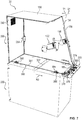
- FIG. 10 shows a perspective side view of the device 10 according to FIG Figure 1 .
- the head module 100 comprises a frame 136 which, when the device 10 is ready for operation, is surrounded by housing elements 134, 138, 142.
- a lateral housing element of the frame 136 is shown in FIG Figure 2 not shown, so that a view into the interior of the head module 100 is possible.
- a side wall of the safe module 200 is not shown, so that a view into the interior of the safe module 200 is possible.
- a first electromechanical locking unit 130 is firmly connected via a fastening element 148 to a cross member, not shown, of the frame 136, a second electromechanical locking unit 132 is connected via the fastening element 150 to a further cross member, not shown, of the frame 136 and is arranged opposite the first electromechanical locking unit 130 .
- a pivoting of the front panel frame 106 in the locked state about the pivot axis S1 is prevented.
- a third electromechanical locking unit 140 is provided, which is firmly connected to the base support 143 of the frame 136 and securely locks the note handling unit 102 to the head module 100 in the locked state.
- the third locking unit 140 prevents the locked State of pulling out of note handling unit 102 from head module 100 with front panel 104 open.
- the electromechanical locking units 130, 132, 140 each have a manually operated emergency release, the structure of which is also shown below in connection with Figure 3 is described in more detail.
- the emergency unlocking of the first electromechanical locking unit 130 comprises a first actuating wire 144
- the emergency unlocking of the second electromechanical locking unit 132 comprises a second actuating wire 142
- the emergency unlocking of the third electromechanical locking unit 140 comprises a third actuating wire 146.
- each actuating wire 142, 144, 146 is coupled to the corresponding electromechanical locking unit 130, 132, 140 and the second end is guided into the safe module 200.
- an emergency unlocking of the electromechanical locking units 130, 132, 140 is only possible if an authorized user has access to the actuating wires 142, 144, 146 via an opening in the safe module 200.
- the actuating wires 142, 144, 146 are securely guided within the fastening elements 148, 150 and within cable guide covers 152, in the illustration according to Figure 2 one of the cable routing covers with the reference numeral 152 is visible.
- the cable management covers 152 prevent in particular manipulation of the actuating wires 142, 144, 146 by unauthorized third parties.
- Figure 3 shows a detailed view after Figure 2 , in which the connection between the front panel frame 106 and the second electromechanical locking unit 132 is shown in the locked state.
- the structure and function of the second electromechanical locking unit 132, which, with the necessary changes, also apply to the first electromechanical locking unit 130, are described in more detail below.
- the locking unit 132 comprises a hook-shaped first engagement element 167 which can be moved from a locking state to an unlocking state and vice versa with the aid of an electric drive unit arranged in a housing element 169.
- the first engagement element 167 engages in a bow-shaped engagement region 162 of a second engagement element 160, which is firmly connected to the front panel frame 106.
- the first engagement element 167 and the second engagement element 160 are in engagement with one another in the shown locking state.
- connection can be mechanically released by the emergency release with the aid of the second actuating wire 142.
- the mechanical actuating wire 142 is pulled in the direction R1, so that a first closure element 163 mounted via a spring element 161 is moved about the axis of rotation D1.
- This movement of the first closure element 163 causes a release of the movement of a second closure element 165 in the direction R2, whereby a movement of the first engagement element 167 about the axis of rotation D2 is released via a mechanical engagement such that the engagement between the first engagement element 167 and the second engagement element 160 is resolved.
- Other emergency release mechanisms are also possible in other embodiments.
- the structure of the third locking unit 140 corresponds to the structure of the described second electromechanical locking unit 132.
- the third electromechanical locking unit 140 does not connect the front panel frame 106 to the frame 136, but rather the note handling unit 102 to the base support 143 of the frame 136, so that in the locked state, the note handling unit 102 is prevented from being pulled out of the head module 100 .
- the banknote handling unit 102 is mounted in particular on rails and can be pulled out of the head module 100 forwards in the unlocked state.
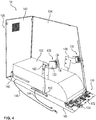
- FIG. 11 shows a perspective view of the head module 100 according to the preceding figures, FIG Figure 4 for a better explanation of the embodiment, some elements of the device 10 are not shown.
- a mechanical locking arrangement 170 can be seen in particular, which is firmly connected to the front panel frame 106 via a base element 172.
- a detailed view of the mechanical locking assembly 170 is related to FIG Figure 4 shown.
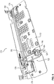
- FIG. 5 3 shows a perspective view of the mechanical locking arrangement 170.
- the mechanical locking arrangement 170 comprises a first mechanically actuatable locking element 174 and a second mechanically actuable locking element 176.
- Two bolts 178, 180 are arranged in a fixed position in the head module 100 and protrude from the base support 143. The bolts 178, 180 with the locking elements are in the locked state 174, 176 in engagement, so that a pivoting of the front panel frame 106 with the locking arrangement 170 about the pivot axis S1 is prevented.
- the key 124 engages in a lock 184, which is mechanically coupled to the first locking element 176 via a coupling element 182 such that when the key 124 is actuated in an open lock position, the engagement of the bolt 178 with the locking element 176 of the frame 136 is released.
- the first locking element 176 and the second locking element 178 are mechanically coupled to one another via a connecting rod 185 such that when the key 124 is actuated, the engagement of the bolt 180 with the locking element 174 is also released.
- only one mechanically actuatable locking element 174, 178 can be provided.
- a separate lock 184 and a separate mechanical coupling element 182 can be provided for each mechanically actuatable locking element 174, 178.
- electromechanical locking units instead of the mechanically actuatable locking elements 174, 178.
- the lock 184 is further coupled to an electrical switch 186, the electrical switch 186 being designed and arranged in such a way that it is activated when the When the lock 184 is in the open lock position, a control signal is generated with the aid of the key 124 and transmitted to the control unit (not shown) of the device 10.
- FIG. 13 shows a front view of the mechanical locking assembly 170 of FIG Figure 5 , from which in particular the protrusion of the bolts 178 and 180 in the locked state from the locking arrangement 170 can be seen.
- the device 10 comprises in addition to the Figures 1 to 5 elements shown at least one authentication unit, not shown, for determining authentication information of a user.
- the authentication unit comprises a card reader, an encrypted PIN pad and a monitor.
- an NFC reader, a fingerprint reader and / or a barcode reader can also be provided. The following describes the method with which, with the exception of the emergency unlocking, a change from the locked state to the unlocked state of the device 10 is possible.
- the user must first identify himself by entering an individual card into the card reader.
- a display on the monitor prompts the user to enter an individual numerical code (PIN) via the Input keyboard.
- PIN numerical code
- This authentication information which in particular includes the card number and the numerical code (PIN) is transmitted from the authentication unit to the control unit and verified by the control unit.
- the authentication means can be used independently of one another; in particular, a PIN can be entered independently of the reading of a card.
- the control unit With the verification of the authentication information, the control unit attests to the authorization to carry out predetermined actions by the user.
- the determination of the authentication information by the authentication unit and the verification of the authentication information by the control unit are summarized below under the term “authentication”.
- Authentication is to be distinguished from simple identification, in which only an identity is established, but its authenticity is not checked.
- the user must operate the lock 184 with the aid of the key 124 in a second step.
- the lock 184 By actuating the lock 184, the first and the second mechanically actuatable locking element 174, 176 are unlocked, and the electrical switch 186 is actuated.
- the switch 186 outputs the corresponding control signal to the control unit, which is processed by the latter.
- the control unit controls the drive units for driving the movement of the first engagement elements 167 of the first and second locking units 132, 134, 140 in such a way that the respective connections between the first Engagement members 167 and the second engagement members 160 are released.
- the unlocking of the first and the second electromechanical locking units 130, 132 has the consequence that the front panel 104 can be pivoted relative to the frame 136 about the pivot axis S1.
- the unlocking of the third electromechanical locking unit 140 has the effect that the note handling unit 104 can be pulled out and removed from the head module 100.
- the note handling unit 104 can only be moved out of the head module if the user enters further information, in particular a numerical code, into the encrypted PIN pad and if this further information is verified by the control unit.
- the encrypted PIN pad can be replaced by a touch module.
- the authentication unit can, as an alternative or in addition to the card reader, comprise a near-field communication module and / or a barcode reader.
- the authentication unit comprises a sensor unit for capturing biometric data, in particular a camera and / or a fingerprint sensor, so that an authorized user can be authenticated on the basis of biometric properties.
- FIG. 7 shows a value note handling device 20 according to a second embodiment. Elements with the same function or the same structure have the same reference symbols.
- the device 20 comprises a head module 300 and the safe module 200.
- the head module 300 comprises an arrangement for locking and unlocking the front panel.
- FIG Figure 7 individual elements of the device 20 are shown in FIG Figure 7 not shown.
- the front panel 104 is not shown, which in the locked state is locked to the frame 136 of the head module 300 such that the note handling unit 102 and the transfer opening 302 to the safe module 200 are protected from access by an unauthorized user.
- the note handling unit 102 in the second exemplary embodiment is in particular not connected to the base support 143 via an electromechanical locking unit 140.
- the device 20 comprises a lockable and lockable door 342 which is only accessible from the rear of the device 20.
- the device 20 further comprises an unlocking mechanism 390 for unlocking the mechanical Locking elements 374 and 376.
- the unlocking mechanism 390 replaces the key 124 and lock 184 from the first embodiment described above.
- the unlocking mechanism 390 comprises at least one unlocking rod 391, which is guided in two rod guide covers 392, 394 and is resiliently mounted in the rod guide cover 394 via a spring element 396.
- the authentication information which in particular includes the card number and the numerical code (PIN) or only the numerical code (PIN), is transmitted from the authentication unit to the control unit (not shown) and is verified by the control unit.
- a locking unit (not shown) for unlocking the door 342 is activated in such a way that the door 342 is unlocked.
- the unlocked door 342 is then opened in a next step by the authorized user, with an electrical switch 386 being provided which is designed and arranged in such a way that it is activated when the door 342 is opened a control signal is generated and transmitted to the control unit of the device 20.
- the control unit unlocks the first and second electromechanical locking units 130, 132 according to the method described in connection with the first exemplary embodiment.
- the user has to actuate the unlocking mechanism 390 to unlock the mechanically actuatable locking elements 374, 376.
- Figure 8 shows a detailed view of the device 20 according to FIG Figure 7 showing the mechanical locking assembly 370 and part of the locking mechanism 390.
- the unlocking mechanism 390 is actuated, ie when the unlocking rod 391 is moved in the direction R3, the engagement of the bolt 178 with the locking element 376 is released.
- the first locking element 374 and the second locking element 376 are mechanically coupled to one another via the connecting rod 185 such that when the unlocking mechanism 390 is actuated, the engagement of the bolt 180 with the locking element 374 is also released.
- the unlocking of the mechanically actuatable locking elements 374, 376 has the consequence that the front panel 104 with the locking arrangement 370 is opposite the frame 136 is pivotable about the pivot axis S1.
- the front panel 104 By pivoting the front panel 104 in the pivoting direction T1, access to the hardware components of the head module 300 of the device 20 is possible.
- the banknote handling unit 102 can be displaced counter to the direction R3, ie in the direction of the door 342 through the door opening.
- the front panel 104 with the locking arrangement 370 is pivoted counter to the pivoting direction T1 about the pivot axis S1 until a latching connection between the mechanically actuated locking elements 374, 376 and the respective bolt 178, 180 is made.
- an electrical switch is activated inside the locking elements 374, 376, which sends a signal to the control unit, the control unit detecting the locking state of the locking elements 374, 376 upon receipt of the signal.
- the mechanically actuatable locking elements 174, 176 also change from the unlocked state to the locked state.
- the electromechanical locking units 130, 132, 140 also change from the unlocked state to the locked state when a latching connection is established.
- a signal is sent to the control unit, the control unit, when receiving the signal, activating a drive unit of the electromechanical locking units 130, 132 in such a way that the first engagement element 167 in the bow-shaped engagement region 162 engages.
- the device 20 does not have a manually operated emergency release with operating wires for the electromechanical locking units 130, 132.
- An emergency unlocking of the locking units 130, 132 is possible with the door 342 open with the aid of a hand tool, in particular a screwdriver.
- the arrangement for locking a head module 100, 300 of a device 10, 20 comprises both the unlocking mechanism 390 and the lock 184, so that mechanically actuatable locking elements 174, 176, 374, 376 are also activated when the lock 184 is actuated With the help of a key 124 and the unlocking mechanism 390 can be unlocked.
- Figure 9 shows a schematic side view of a device 30 for handling notes of value according to a third embodiment.
- This differs from the first two embodiments in that the front panel 104 is not pivotably connected to the frame 436 of the head module 400. Rather, the front panel 104 is firmly connected via a housing 406 to two oppositely arranged telescopic rail arrangements, in the illustration according to Figure 3 only the telescopic rail arrangement 404 identified by the reference symbol is visible.
- the telescopic rail assemblies 404 are each arranged on a cross member 408 of the frame 436.
- the electromechanical locking unit (not visible) is arranged in such a way that the telescopic rails of the telescopic rail arrangements 404 are prevented from being pulled out in the locked state of the electromechanical locking unit. A translational movement of the front panel 104 together with the housing 406 in the direction R4 is therefore only possible in an unlocked state the electromechanical locking unit possible.
- the locking unit is preferably the same in structure or function as in connection with the Figures 1 and 2 described electromechanical locking units 130, 132, 140 correspond.
- the front panel 104 is connected to the frame 136, 436 in such a way that it can be removed from the frame 136, 436 in the unlocked state, that is to say can be completely detached and thus removed.
Landscapes
- Business, Economics & Management (AREA)
- Accounting & Taxation (AREA)
- Finance (AREA)
- Physics & Mathematics (AREA)
- General Physics & Mathematics (AREA)
- Strategic Management (AREA)
- General Business, Economics & Management (AREA)
- Engineering & Computer Science (AREA)
- Theoretical Computer Science (AREA)
- Lock And Its Accessories (AREA)
- Financial Or Insurance-Related Operations Such As Payment And Settlement (AREA)
Abstract
Description
- Die Erfindung betrifft eine Anordnung zum sicheren Verschließen eines Kopfmoduls einer Vorrichtung zur Handhabung von Wertscheinen. Die Anordnung umfasst mindestens ein Kopfmodul, das zumindest einen Rahmen und eine Frontblende umfasst. Ferner umfasst die Anordnung mindestens eine Sensoreinheit zur Ausgabe eines Steuersignals, eine Authentifizierungseinheit zum Ermitteln von Authentifizierungsinformationen und eine Steuereinheit.
- Die Anzahl von Sprengungen von Vorrichtungen zur Handhabung von Wertscheinen, insbesondere von Geldautomaten, nimmt seit dem Jahr 2013 deutlich zu. Die durch die Sprengungen verursachte Schadenshöhe übersteigt in vielen Fällen deutlich den Wert der erlangten Beute, in Einzelfällen kommt es zu Sachschäden in Millionenhöhe. Bei einer Sprengung werden üblicherweise die Frontblenden der Geldautomaten aufgebrochen, ein zündfähiges Gemisch, zum Beispiel Luft mit Propangas oder Luft mit Acetylen wird in das Tresormodul geleitet und zur Explosion gebracht. Alternativ werden auch feste Sprengstoffe oder Pyrotechnik verwendet.
- Aus dem Stand der Technik sind Abwehrmaßnahmen bekannt, bei denen als Diebstahlsicherung sogenannte Farbbomben eingesetzt werden. Bei einer nicht befugten Öffnung des Tresormoduls wird die Farbbombe derart ausgelöst, dass der Wertscheininhalt durch Farbe unbrauchbar für die Täter gemacht wird. Diese Maßnahmen haben allerdings den Nachteil, dass die Sprengung selbst und die damit verbundenen Schäden und Gefahren nicht vermieden werden.
- Es ist Aufgabe der Erfindung, eine Anordnung zum sicheren Verschließen einer Kopfeinheit einer Vorrichtung zur Handhabung von Wertscheinen anzugeben, die ein unerlaubtes Öffnen der Vorrichtung verhindert und dadurch ein besonders hohes Maß an Sicherheit vor Sprengung und Diebstahl ermöglicht.
- Diese Aufgabe wird durch die Anordnung mit den Merkmalen des unabhängigen Anspruchs gelöst. Vorteilhafte Weiterbildungen sind in den abhängigen Ansprüchen angegeben.
- Bei der Anordnung mit den Merkmalen des Anspruchs 1 umfasst das Kopfmodul mindestens eine elektromechanische Verriegelungseinheit, die in einem Verriegelungszustand eine Verriegelung der Frontblende mit dem Rahmen erzeugt, und die die Verriegelung in einem Entriegelungszustand aufhebt. Die Steuereinheit ist ausgebildet, eine Detektion des Steuersignals und eine Verifizierung der Authentifizierungsinformation durchzuführen. Ferner ist die Steuereinheit ausgebildet, die elektromechanische Verriegelungseinheit derart anzusteuern, dass eine Änderung der elektromechanischen Verriegelungseinheit von dem Verriegelungszustand in den Entriegelungszustand nur bei Detektion des Steuersignals und bei erfolgreicher Verifizierung der Authentifizierungsinformation erfolgt. Dadurch wird eine besonders sichere, gegen Manipulation geschützte Verriegelung der Frontblende mit dem Rahmen erzeugt.
- Es ist vorteilhaft, wenn die Anordnung mindestens ein mechanisch betätigbares Verriegelungselement umfasst, wobei die Frontblende nur bei einer Entriegelung des mindestens einen mechanisch betätigbaren Verriegelungselements und der mindestens einen elektromechanischen Verriegelungseinheit relativ zum Rahmen verschwenkbar oder von dem Rahmen entfernbar oder mittels Teleskopschienen horizontal und/oder vertikal relativ zum Rahmen verschiebbar ist. Somit wird erreicht, dass eine Manipulation, insbesondere ein Aufbrechen der Frontblende, erheblich erschwert ist.
- Ferner ist es vorteilhaft, wenn mindestens ein stabförmiges Verriegelungselement an einer festen Position im Kopfmodul angeordnet ist und im Verriegelungszustand mit dem mechanisch betätigbaren Verriegelungselement in Eingriff steht. Dadurch wird ein Verschwenken der Frontblende um eine Schwenkachse oder ein Entfernen der Frontblende oder ein horizontales und/oder vertikales Verschieben der Frontblende relativ zum Rahmen verhindert.
- Besonders vorteilhaft ist es, wenn die Steuereinheit ausgebildet ist, ausgehend von den Authentifizierungsinformationen die Berechtigung eines Benutzers zum Öffnen der Frontblende zu ermitteln. Dadurch wird erreicht, dass die Frontblende bei Fehlschlagen der Authentifizierung im Verriegelungszustand verbleibt.
- Bei einer vorteilhaften Ausführungsform umfasst die Sensoreinheit ein Schloss und einen elektrischen Schalter, wobei der elektrische Schalter derart ausgebildet und angeordnet ist, dass er beim Betätigen des Schlosses mit Hilfe eines Schlüssels das Steuersignal erzeugt. Dadurch wird eine besonders einfache und zuverlässige Erzeugung des Steuersignals erreicht.
- Es ist ferner vorteilhaft, wenn beim Betätigen des Schlosses mit Hilfe des Schlüssels der Eingriff des stabförmigen Verriegelungselements mit dem mechanisch betätigbaren Verriegelungselement gelöst wird. Dadurch wird ein besonders einfaches Entriegeln der mechanisch betätigbaren Verriegelungselemente und ein kompakter Aufbau der Anordnung erreicht.
- Bei einer vorteilhaften Ausführungsform hat die elektromechanische Verriegelungseinheit eine manuell betätigbare Notentriegelung, die mit Hilfe eines mechanischen Betätigungselements betätigbar ist, wobei das mechanische Betätigungselement vorzugsweise einen Betätigungsdraht oder einen Betätigungsseilzug umfasst, dessen eines Ende mit der elektromechanischen Verriegelungseinheit gekoppelt ist und dessen anderes Ende in ein weiteres Modul der Vorrichtung zur Handhabung von Wertscheinen, vorzugsweise in ein Tresormodul, geführt ist, wobei das mechanische Betätigungselement im weiteren Modul nur über eine Öffnung im weiteren Modul für einen berechtigten Benutzer zugänglich ist. Dadurch wird sichergestellt, dass eine Betätigung der Notentriegelung im Falle eines unberechtigten Zugriffs auf das Kopfmodul nicht durch den unbefugten Dritten durchgeführt werden kann.
- Bei einer weiteren vorteilhaften Ausführungsform, ist die Sensoreinheit ausgebildet, das Öffnen einer Tür des Kopfmoduls zu detektierten und ausgehend von der Detektion des Öffnens der Tür das Steuersignal auszugeben und an die Steuereinheit zu übermitteln. Dadurch wird ein besonders einfacher Aufbau der Anordnung erreicht, der sich insbesondere für Outdoor-Systeme eignet, bei denen der Zugang "Through-the-Wall" erfolgt, , das heißt für Geldautomaten, die in einer Öffnung einer Außenwand oder einer Fensterfront eingebaut sind. Bei diesen Geldautomaten sind die Bedieneinheit und/oder die Frontblende durch die Öffnung erreichbar, während das Tresormodul in der Regel von hinten, das heißt von der der Frontblende entgegengesetzten Seite, nur für die berechtigten Benutzer zugänglich ist.
- Es ist vorteilhaft, wenn bei einer Betätigung des mechanisch betätigbaren Verriegelungselements mit einem Entriegelungsmechanismus der Eingriff des stabförmigen Verriegelungselements mit dem mechanisch betätigbaren Verriegelungselement gelöst wird, wobei der Entriegelungsmechanismus nur bei geöffneter Tür des Kopfmoduls für einen berechtigten Benutzer zugänglich ist. Dadurch wird eine Entriegelung der mechanisch betätigbaren Verriegelungselemente durch Manipulationen an der Vorderseite der Vorrichtung, das heißt an der Frontblendenseite, verhindert.
- Ferner ist es vorteilhaft, wenn die elektromechanische Verriegelungseinheit eine manuell betätigbare Notentriegelung hat, die mit Hilfe eines Entriegelungswerkzeuges betätigbar ist, wobei eine Betätigung der Notentriegelung nur bei geöffneter Tür des Kopfmoduls möglich ist. Dadurch wird einer Notentriegelung durch unbefugte Dritte wirksam entgegengewirkt.
- Bei einer vorteilhaften Ausführungsform umfasst das Kopfmodul eine erste mit der Frontblende oder mit dem Rahmen fest verbundene elektromechanische Verriegelungseinheit und eine zweite mit der Frontblende oder mit dem Rahmen fest verbundene elektromechanisches Verriegelungseinheit, wobei die zweite elektromechanische Verriegelungseinheit an einer der ersten elektromechanischen Verriegelungseinheit gegenüberliegenden Seite des Rahmens oder der Frontblende angeordnet ist. Dadurch wird eine besonders hohe Sicherheit gegen den Aufbruch der Vorrichtung erreicht.
- Ferner ist es vorteilhaft, wenn die mechanisch betätigbare Verriegelungseinheit einen Schalter zur Ausgabe eines Schaltsignals umfasst, wenn die Steuereinheit ausgebildet ist, das Schaltsignal zu detektieren, und wenn die Steuereinheit ausgebildet ist, die elektromechanische Verriegelungseinheit derart anzusteuern, dass eine Änderung der elektromechanischen Verriegelungseinheit von dem Entriegelungszustand in den Verrieglungszustand bei Detektion des Schaltsignals und bei Verifizierung der Authentifizierungsinformationen erfolgt. Dadurch wird ein besonders kompakter, sicherer und einfacher Aufbau der Anordnung erreicht.
- Es ist besonders vorteilhaft, wenn der Rahmen des Kopfmoduls in einem Gehäuse des Kopfmoduls integriert ist oder wenn der Rahmen des Kopfmoduls von dem Gehäuse des Kopfmoduls umgegeben ist. Dadurch wird eine besonders stabile Verbindung zwischen dem Rahmen und dem Kopfmodul erreicht.
- Es ist voreilhaft, wenn eine im Kopfmodul angeordnete Wertscheinhandhabungseinheit mit Hilfe einer weiteren elektromechanischen Verriegelungseinheit in dem Verriegelungszustand mit dem Rahmen verriegelt ist, und wenn die Steuereinheit ausgebildet ist, die weitere elektromechanische Verriegelungseinheit derart anzusteuern, dass eine Änderung der weiteren elektromechanischen Verriegelungseinheit von dem Verriegelungszustand in den Entriegelungszustand nur bei Detektion des Steuersignals und bei erfolgreicher Verifizierung der Authentifizierungsinformation erfolgt. Dadurch wird ein Herauslösen der Wertscheinhandhabungseinheit aus dem Kopfmodul durch einen unbefugten Dritten besonders wirksam erschwert.
- Bei einer vorteilhaften Ausführungsform erfolgt eine Bewegung der weiteren elektromechanischen Verriegelungseinheit von dem Verriegelungszustand in den Entriegelungszustand nur bei Vorliegen einer weiteren Authentifizierungsinformation des Benutzers. Dadurch wird ein besonders hohes Maß an Sicherheit gegen ein Verschieben oder Entfernen der Wertscheinhandhabungseinheit erreicht.
- Weitere Merkmale und Vorteile ergeben sich aus der folgenden Beschreibung, welche in Verbindung mit den beigefügten Figuren die Erfindung Ausführungsbeispiele näher erläutert.
- Es zeigt:
- Fig. 1
- eine Vorderansicht einer Vorrichtung zur Handhabung von Wertscheinen mit einem Kopfmodul und einem Tresormodul gemäß einem ersten Ausführungsbeispiel,
- Fig. 2
- eine perspektivische Seitenansicht der Vorrichtung nach
Figur 1 , - Fig. 3
- eine Detailansicht der Vorrichtung nach
Figur 2 , - Fig. 4
- eine perspektivische Ansicht des Kopfmoduls nach den vorhergehenden Figuren,
- Fig. 5
- eine perspektivische Ansicht einer mechanischen Verriegelungsanordnung der Vorrichtung nach den vorhergehenden Figuren,
- Fig. 6
- eine Vorderansicht der mechanischen Verriegelungsanordnung nach
Figur 5 , - Fig. 7
- eine perspektivische Ansicht einer Vorrichtung zur Handhabung von Wertscheinen gemäß einem zweiten Ausführungsbeispiel,
- Fig. 8
- eine Detailansicht der Vorrichtung nach
Figur 7 , und - Figur 9
- eine schematische Seitenansicht einer Vorrichtung zur Handhabung von Wertscheinen gemäß einem dritten Ausführungsbeispiel.
-
Figur 1 zeigt eine Vorderansicht einer Vorrichtung 10 zur Handhabung von Wertscheinen gemäß einem ersten Ausführungsbeispiel. Zur besseren Erläuterung des Ausführungsbeispiels sind einzelne Elemente der Vorrichtung 10 nicht dargestellt. Die Vorrichtung 10 umfasst ein Kopfmodul 100 und ein Tresormodul 200. In dem Tresormodul 200 sind mehrere nicht dargestellte Geldkassetten zur Aufnahme von Wertscheinen aufnehmbar. - Das Kopfmodul 100 umfasst eine Wertscheinhandhabungseinheit 102 zur Ausgabe von auszuzahlenden Wertscheinen an eine Bedienperson und/oder zur Eingabe von durch eine Bedienperson einzuzahlender Wertscheine. Sowohl das Tresormodul 200 als auch das Kopfmodul 100 haben jeweils eine Übergabeöffnung, durch die Wertscheine von dem Kopfmodul 100 in das Tresormodul 200 transportiert werden können sowie umgekehrt von dem Tresormodul 200 in das Kopfmodul 100. Bei einer alternativen Ausführungsform kann die Vorrichtung 10 auch nur der Auszahlung von Wertscheinen dienen. In diesem Fall sind ausschließlich Wertscheine von dem Tresormodul 200 dem Kopfmodul 100 über die Übergabeöffnungen zuführbar. Bei einer weiteren alternativen Ausführungsform der Erfindung können das Tresormodul 200 und das Kopfmodul 100 auch ein Tresormodul 200 und ein Kopfmodul 100 eines automatischen Kassensystems oder einer automatischen Tresorkasse sein.
- Das Kopfmodul 100 umfasst eine Frontblende 104, mit einem Frontblendenrahmen 106 und einer in
Figur 1 nicht dargestellten Frontblendenverkleidung. Die Frontblende 104 ist mit einem inFigur 1 von dem Frontblendenrahmen 106 verdeckten Rahmen 136 des Kopfmoduls 100 schwenkbar verbunden. InFigur 1 ist ein Verriegelungszustand der Vorrichtung 10 gezeigt, bei welchem die Frontblende 104 mit dem Rahmen 136 des Kopfmoduls 100 derart verriegelt ist, dass die Wertscheinhandhabungseinheit 102 und die Übergabeöffnungen vor einem Zugriff eines unberechtigten Benutzers geschützt sind. - Die Frontblende 104 hat mehrere Öffnungen 108 bis 116, in die Hardwarekomponenten, wie ein Encrypted PIN Pad, eine Anzeigeeinheit, insbesondere ein Touchscreen oder eine Kombination aus Anzeigeeinheit und Encrypted PIN Pad zur Pin-Eingabe, ein Kartenleser, eine Kamera, ein Fingerabdrucksensor, ein Ein-und/oder Ausgabefach für Wertscheine, ein Nahfeldkommunikationsmodul, ein Barcodeleser, ein Belegdrucker und/oder eine Wertscheinausgabeeinheit in die Frontblende integriert werden können, wobei zumindest ein Teil der Hardwarekomponenten fest mit dem Frontblendenrahmen 106 verbunden und zusammen mit dem Frontblendenrahmen 106 verschwenkbar sind. Bei einer vorteilhaften Ausführungsform kann der Touchscreen derart ausgestaltet sein, dass eine sichere PIN-Eingabe über den Touchscreen erfolgen kann. Die Hardwarekomponenten dienen insbesondere als Mensch-Maschine-Schnittstelle für eine Bedienperson zum Bedienen der Vorrichtung 10. In der Darstellung nach
Figur 1 sind ferner mechanisch betätigbare Verriegelungselemente 174, 176 und ein Schlüssel 124 sichtbar, deren Aufbau und Funktion insbesondere in Zusammenhang mitFigur 3 noch näher beschrieben wird. -
Figur 2 zeigt eine perspektivische Seitenansicht der Vorrichtung 10 nachFigur 1 . Elemente mit gleichem Aufbau oder gleicher Funktion haben dieselben Bezugszeichen. Das Kopfmodul 100 umfasst einen Rahmen 136, der im betriebsbereiten Zustand der Vorrichtung 10 von Gehäuseelementen 134, 138, 142 umgeben ist. Zur besseren Erläuterung des Ausführungsbeispiels ist ein seitliches Gehäuseelement des Rahmens 136 inFigur 2 nicht dargestellt, sodass eine Sicht in das Innere des Kopfmoduls 100 möglich ist. Ferner ist eine Seitenwand des Tresormoduls 200 nicht dargestellt, sodass eine Sicht in das Innere des Tresormoduls 200 möglich ist. - Eine erste elektromechanisches Verriegelungseinheit 130 ist über ein Befestigungselement 148 fest mit einem nicht dargestellten Querträger des Rahmens 136 verbunden, eine zweite elektromechanische Verriegelungseinheit 132 ist über das Befestigungselement 150 fest mit einem weiteren nicht dargestellten Querträger des Rahmens 136 verbunden und der ersten elektromechanischen Verriegelungseinheit 130 gegenüberliegend angeordnet. Mit Hilfe der elektromechanischen Verriegelungseinheiten 130, 132 wird insbesondere ein Verschwenken des Frontblendenrahmens 106 im Verriegelungszustand um die Schwenkachse S1 verhindert.
- Ferner ist eine dritte elektromechanische Verriegelungseinheit 140 vorgesehen, die fest mit dem Bodenträger 143 des Rahmens 136 verbunden ist und die Wertscheinhandhabungseinheit 102 in dem Verriegelungszustand sicher mit dem Kopfmodul 100 verriegelt. Bei einer vorteilhaften Ausführungsform verhindert die dritte Verriegelungseinheit 140 im verriegelten Zustand ein Herausziehen der Wertscheinhandhabungseinheit 102 aus dem Kopfmodul 100 bei geöffneter Frontblende 104.
- Die elektromechanischen Verriegelungseinheiten 130, 132, 140 haben jeweils eine manuell betätigbare Notentriegelung, deren Aufbau nachfolgend auch in Zusammenhang mit
Figur 3 näher beschrieben wird. Die Notentriegelung der ersten elektromechanischen Verriegelungseinheit 130 umfasst im vorliegenden Ausführungsbeispiel einen ersten Betätigungsdraht 144, die Notentriegelung der zweiten elektromechanischen Verriegelungseinheit 132 umfasst einen zweiten Betätigungsdraht 142 und die Notentriegelung der dritten elektromechanischen Verriegelungseinheit 140 umfasst einen dritten Betätigungsdraht 146. - Ein erstes Ende jedes Betätigungsdrahtes 142, 144, 146 ist mit der entsprechenden elektromechanischen Verriegelungseinheit 130, 132, 140 gekoppelt und das zweite Ende ist in das Tresormodul 200 geführt. Hierdurch ist eine Notentriegelung der elektromechanischen Verriegelungseinheiten 130, 132, 140 nur dann möglich, wenn ein berechtigter Benutzer über eine Öffnung im Tresormodul 200 Zugang zu den Betätigungsdrähten 142, 144, 146 hat. Im Kopfmodul 100 werden die Betätigungsdrähte 142, 144, 146 innerhalb der Befestigungselemente 148, 150 und innerhalb von Kabelführungsabdeckungen 152 sicher geführt, wobei in der Darstellung nach
Figur 2 eine der Kabelführungsabdeckung mit dem Bezugszeichen 152 sichtbar ist. Die Kabelführungsabdeckungen 152 verhindern insbesondere eine Manipulation der Betätigungsdrähte 142, 144, 146 durch unberechtigte Dritte. -
Figur 3 zeigt eine Detailansicht nachFigur 2 , in welcher die Verbindung zwischen dem Frontblendenrahmen 106 und der zweiten elektromechanischen Verriegelungseinheit 132 in dem Verriegelungszustand dargestellt ist. Nachfolgend werden der Aufbau und die Funktion der zweiten elektromechanischen Verriegelungseinheit 132 näher beschrieben, die mit den notwendigen Änderungen auch für die erste elektromechanische Verriegelungseinheit 130 gelten. - In der Darstellung nach
Figur 3 ist zur besseren Beschreibung der Verriegelungseinheit 132 eine inFigur 2 sichtbare Verkleidung 133 der Verriegelungseinheit 132 nicht dargestellt. Die Verriegelungseinheit 132 umfasst ein hakenförmiges erstes Eingriffselement 167, das mit Hilfe einer in einem Gehäuseelement 169 angeordneten elektrischen Antriebseinheit von einem Verriegelungszustand in einen Entriegelungszustand und vice versa bewegbar ist. In dem dargestellten Verriegelungszustand greift das erste Eingriffselement 167 in einen bügelförmigen Eingriffsbereich 162 eines zweiten Eingriffselements 160, das fest mit dem Frontblendenrahmen 106 verbunden ist. Somit stehen das erste Eingriffselement 167 und das zweite Eingriffselement 160 in dem gezeigten Verriegelungszustand miteinander in Eingriff. - Ein Lösen der Verbindung zwischen dem ersten Eingriffselement 167 der Verriegelungseinheit 132 und dem zweiten Eingriffselement 160 ist im Verriegelungszustand, insbesondere durch äußere Krafteinwirkung, nicht möglich. Jedoch kann die Verbindung im Notfall durch die Notentriegelung mit Hilfe des zweiten Betätigungsdrahtes 142 mechanisch gelöst werden. Bei dieser Notentriegelung wird der mechanische Betätigungsdraht 142 in Richtung R1 gezogen, sodass ein über ein Federelement 161 gelagertes erstes Verschlusselement 163 um die Drehachse D1 bewegt wird. Diese Bewegung des ersten Verschlusselements 163 bewirkt eine Freigabe der Bewegung eines zweiten Verschlusselements 165 in Richtung R2, wodurch über einen mechanischen Eingriff eine Bewegung des ersten Eingriffselements 167 um die Drehachse D2 derart freigegeben wird, dass der Eingriff zwischen dem ersten Eingriffselement 167 dem zweiten Eingriffselement 160 gelöst wird. Bei anderen Ausführungsformen sind auch andere Notentriegelungsmechanismen möglich.
- Ferner kann im normalen Betrieb der Vorrichtung 10, d.h. nicht bei Notentriegelung, die Verbindung zwischen dem ersten Eingriffselement 167 und dem zweiten Eingriffselement 160 elektromechanisch gelöst werden, indem die elektrische Antriebseinheit zum Antrieb der Bewegung des ersten Eingriffselements 167 mit Hilfe einer nicht dargestellten Steuereinheit angesteuert wird.
- Der Aufbau der dritten Verriegelungseinheit 140 entspricht dem Aufbau der beschriebenen zweiten elektromechanischen Verriegelungseinheit 132. Im Unterschied zu der ersten und zu der zweiten elektromechanischen Verriegelungseinheit 130, 132 verbindet die dritte elektromechanische Verriegelungseinheit 140 allerdings nicht den Frontblendenrahmen 106 mit dem Rahmen 136, sondern die Wertscheinhandhabungseinheit 102 mit dem Bodenträger 143 des Rahmens 136, sodass im Verriegelungszustand ein Herausziehen der Wertscheinhandhabungseinheit 102 aus dem Kopfmodul 100 verhindert wird. Die Wertscheinhandhabungseinheit 102 ist insbesondere auf Schienen gelagert und ist im entriegelten Zustand nach vorn aus dem Kopfmodul 100 herausziehbar.
-
Figur 4 zeigt eine perspektivische Ansicht des Kopfmoduls 100 nach den vorhergehenden Figuren, wobei auch inFigur 4 zur besseren Erläuterung des Ausführungsbeispiels einige Elemente der Vorrichtung 10 nicht dargestellt sind. In Figur 4 ist insbesondere eine mechanische Verriegelungsanordnung 170 sichtbar, die über ein Bodenelement 172 fest mit dem Frontblendenrahmen 106 verbunden ist. Eine Detailansicht der mechanischen Verriegelungsanordnung 170 ist im Zusammenhang mitFigur 4 gezeigt. -
Figur 5 zeigt eine perspektivische Ansicht der mechanischen Verriegelungsanordnung 170. Die mechanische Verriegelungsanordnung 170 umfasst ein erstes mechanisch betätigbares Verriegelungselement 174 und ein zweites mechanisch betätigbares Verriegelungselement 176. Zwei Bolzen 178, 180 sind an einer festen Position im Kopfmodul 100 angeordnet und stehen aus dem Bodenträger 143 heraus. Im Verriegelungszustand stehen die Bolzen 178, 180 mit den Verriegelungselementen 174, 176 in Eingriff, sodass ein Verschwenken des Frontblendenrahmens 106 mit der Verriegelungsanordnung 170 um die Schwenkachse S1 verhindert wird. - Der Schlüssel 124 greift in ein Schloss 184, das mit dem ersten Verriegelungselement 176 über ein Koppelungselement 182 derart mechanisch gekoppelt ist, dass bei einer Betätigung des Schlüssels 124 in eine geöffnete Schlossstellung der Eingriff des Bolzens 178 mit dem Verriegelungselement 176 des Rahmens 136 gelöst wird.
- Das erste Verriegelungselement 176 und das zweite Verriegelungselement 178 sind über einen Verbindungsstab 185 derart miteinander mechanisch gekoppelt, dass bei einer Betätigung des Schlüssel 124 auch der Eingriff des Bolzens 180 mit dem Verriegelungselement 174 gelöst wird. Bei einer alternativen Ausführungsform kann auch nur ein mechanisch betätigbares Verriegelungselement 174, 178 vorgesehen sein. Bei einer weiteren alternativen Ausführungsform kann für jedes mechanisch betätigbare Verriegelungselement 174, 178 ein separates Schloss 184 und ein eigenes mechanisches Koppelungselement 182 vorgesehen sein. Ferner ist es bei alternativen Ausführungsformen möglich, anstelle der mechanisch betätigbaren Verriegelungselemente 174, 178 elektromechanische Verriegelungseinheiten vorzusehen.
- Das Schloss 184 ist ferner mit einem elektrischen Schalter 186 gekoppelt, wobei der elektrische Schalter 186 derart ausgebildet und angeordnet ist, dass er beim Betätigen des Schlosses 184 mit Hilfe des Schlüssels 124 in die geöffnete Schlossstellung ein Steuersignal erzeugt und an die nicht dargestellte Steuereinheit der Vorrichtung 10 übermittelt.
-
Figur 6 zeigt eine Vorderansicht der mechanischen Verriegelungsanordnung 170 nachFigur 5 , aus der insbesondere das Herausragen der Bolzen 178 und 180 im verriegelten Zustand aus der Verriegelungsanordnung 170 erkennbar ist. - Die Vorrichtung 10 umfasst neben den in den
Figuren 1 bis 5 dargestellten Elementen mindestens eine nicht dargestellte Authentifizierungseinheit zum Ermitteln von Authentifizierungsinformationen eines Benutzers. Die Authentifizierungseinheit umfasst in der beschriebenen ersten Ausführungsform ein Kartenlesegerät, ein Encrypted PIN Pad und einen Monitor. Alternativ oder zusätzlich können auch ein NFC-Leser, ein Fingerabdruckleser und/oder ein Barcodeleser vorgesehen sein. Nachfolgend wird das Verfahren beschrieben, mit welchem, mit Ausnahme der Notentriegelung, eine Änderung des Verriegelungszustands in den Entriegelungszustand der Vorrichtung 10 möglich ist. - Damit die Vorrichtung 10 von dem Verriegelungszustand in den Entriegelungszustand wechseln kann, muss sich der Benutzer zunächst durch die Eingabe einer individuellen Karte in das Kartenlesegerät identifizieren. In einem zweiten Schritt wird der Benutzer über eine Anzeige am Monitor aufgefordert, einen individuellen Zahlencode (PIN) über die Eingabetastatur einzugeben. Diese Authentifizierungsinformationen, die insbesondere die Kartennummer und den Zahlencode (PIN) umfassen, werden von der Authentifizierungseinheit an die Steuereinheit übermittelt und von der Steuereinheit verifiziert. Bei alternativen Ausführungsformen können die Authentifizierungsmittel unabhängig voneinander eingesetzt werden, insbesondere kann eine PIN-Eingabe unabhängig von dem Lesen einer Karte erfolgen.
- Mit dem Verifizieren der Authentifizierungsinformationen bezeugt die Steuereinheit die Berechtigung zum Durchführen vorbestimmter Handlungen durch den Benutzer. Das Ermitteln der Authentifizierungsinformationen durch die Authentifizierungseinheit und das Verifizieren der Authentifizierungsinformationen durch die Steuereinheit wird nachfolgend unter dem Begriff "Authentifizierung" zusammengefasst. Eine Authentifizierung ist von der einfachen Identifizierung zu unterscheiden, bei welcher lediglich eine Identität festgestellt, deren Echtheit aber nicht überprüft wird.
- Bei erfolgreicher Authentifizierung muss der Benutzer in einem zweiten Schritt das Schloss 184 mit Hilfe des Schlüssels 124 betätigen. Durch die Betätigung des Schlosses 184 werden das erste und das zweite mechanisch betätigbare Verriegelungselement 174, 176 entriegelt, zudem wird der elektrischer Schalter 186 betätigt. Der Schalter 186 gibt das entsprechende Steuersignal an die Steuereinheit aus, das von dieser verarbeitet wird.
- Sobald die Steuereinheit nach der Authentifizierung des Benutzers zusätzlich das Steuersignal des Schalters 186 empfangen hat, steuert die Steuereinheit die Antriebseinheiten zum Antrieb der Bewegung der ersten Eingriffselemente 167 der ersten und zweiten Verriegelungseinheiten 132, 134, 140 derart an, dass die jeweiligen Verbindungen zwischen den ersten Eingriffselementen 167 und den zweiten Eingriffselementen 160 gelöst werden. Die Entriegelung der ersten und der zweiten elektromechanischen Verriegelungseinheiten 130, 132 hat zur Folge, dass die Frontblende 104 gegenüber dem Rahmen 136 verschwenkbar um die Schwenkachse S1 ist. Durch die Entriegelung der dritten elektromechanischen Verriegelungseinheit 140 wird bewirkt, dass die Wertscheinhandhabungseinheit 104 aus dem Kopfmodul 100 herausziehbar und entnehmbar ist.
- Bei einer vorteilhaften Ausführungsform kann die Wertscheinhandhabungseinheit 104 nur dann aus dem Kopfmodul herausbewegt werden, wenn der Benutzer eine weitere Information, insbesondere einen Zahlencode, in das Encrypted PIN Pad eingibt und wenn diese weitere Information von der Steuereinheit verifiziert wird.
- Bei einer alternativen Ausführungsform kann das Encrypted PIN Pad durch ein Touchmodul ersetzt sein. In weiteren alternativen Ausführungsformen kann die Authentifizierungseinheit alternativ oder zusätzlich zum Kartenlesegerät ein Nahfeldkommunikationsmodul und/oder einen Barcodeleser umfassen. In einer weiteren Ausführungsform umfasst die Authentifizierungseinheit eine Sensoreinheit zum Erfassen biometrischer Daten, insbesondere eine Kamera und/oder einen Fingerabdrucksensor, sodass ein berechtigter Benutzer anhand biometrischer Eigenschaften authentifizierbar ist.
-
Figur 7 zeigt eine Wertscheinhandhabungsvorrichtung 20 gemäß einem zweiten Ausführungsbeispiel. Elemente mit gleicher Funktion oder gleichem Aufbau haben dieseleben Bezugszeichen. Die Vorrichtung 20 umfasst ein Kopfmodul 300 und das Tresormodul 200. Das Kopfmodul 300 umfasst eine Anordnung zum Verriegeln und Entriegeln Frontblende. - Zur besseren Erläuterung des Ausführungsbeispiels sind einzelne Elemente der Vorrichtung 20 in
Figur 7 nicht dargestellt. Insbesondere ist inFigur 7 die Frontblende 104 nicht dargestellt, die in dem Verriegelungszustand mit dem Rahmen 136 des Kopfmoduls 300 derart verriegelt ist, dass die Wertscheinhandhabungseinheit 102 und die Übergabeöffnung 302 zum Tresormodul 200 vor einem Zugriff eines unberechtigten Benutzers geschützt sind. Im Unterschied zum ersten Ausführungsbeispiel ist die Wertscheinhandhabungseinheit 102 im zweiten Ausführungsbeispiel insbesondere nicht über eine elektromechanischen Verriegelungseinheit 140 mit dem Bodenträger 143 verbunden. - Die Vorrichtung 20 umfasst eine, nur von der Hinterseite der Vorrichtung 20 zugängliche, verschließ- und verriegelbare Tür 342. Die Vorrichtung 20 umfasst ferner einen Entriegelungsmechanismus 390 zum Entriegeln der mechanischen Verriegelungselemente 374 und 376. Somit ersetzt der Entriegelungsmechanismus 390 den Schlüssel 124 und das Schloss 184 aus dem ersten oben beschriebenen Ausführungsbeispiel. Der Entriegelungsmechanismus 390 umfasst mindestens einen Entriegelungsstab 391, der in zwei Stabführungsabdeckungen 392, 394 geführt und in der Stabführungsabdeckung 394 über ein Federelement 396 federnd gelagert ist.
- Damit bei der Vorrichtung 20 die elektromechanischen Verriegelungseinheiten 130, 132 und die mechanisch betätigbaren Verriegelungselemente 374, 376 von dem Verriegelungszustand in den Entriegelungszustand wechseln können, muss sich ein Benutzer, wie auch beim ersten Ausführungsbeispiel, zunächst mit Hilfe der Authentifizierungseinheit identifizieren. Die Authentifizierungsinformationen, die insbesondere die Kartennummer und den Zahlencode (PIN) oder nur den Zahlencode (PIN) umfassen, werden von der Authentifizierungseinheit an die nicht dargestellte Steuereinheit übermittelt und von der Steuereinheit verifiziert.
- Zum Entriegeln der Tür 342 muss der Benutzer ein Schloss zum Verschließen der Tür 342 öffnen. Bei einer alternativen Ausführungsform wird bei erfolgreicher Authentifizierung eine nicht dargestellte Verriegelungseinheit zum Entriegeln der Tür 342 derart angesteuert, dass die Tür 342 entriegelt wird. Die entriegelte Tür 342 wird dann in einem nächsten Schritt von dem berechtigten Benutzer geöffnet, wobei ein elektrischer Schalter 386 vorgesehen ist, der derart ausgebildet und angeordnet ist, dass er beim Öffnen der Tür 342 ein Steuersignal erzeugt und an die Steuereinheit der Vorrichtung 20 übermittelt.
- Sobald die Steuereinheit nach der Authentifizierung des Benutzers das Steuersignal des Schalters 386 empfangen hat, entriegelt die Steuereinheit die erste und die zweite elektromechanische Verriegelungseinheit 130, 132 nach dem im Zusammenhang mit dem ersten Ausführungsbeispiel beschriebenen Verfahren. In einem nächsten Schritt muss der Benutzer den Entriegelungsmechanismus 390 zur Entriegelung der mechanisch betätigbaren Verriegelungselemente 374, 376 betätigen.
-
Figur 8 zeigt eine Detailansicht der Vorrichtung 20 nachFigur 7 , in der die mechanische Verriegelungsanordnung 370 und ein Teil des Verriegelungsmechanismus 390 dargestellt sind. Bei Betätigung des Entriegelungsmechanismus 390, d.h. bei Bewegung des Entriegelungsstabs 391 in Richtung R3, wird der Eingriff des Bolzens 178 mit dem Verriegelungselement 376 gelöst. Das erste Verriegelungselement 374 und das zweite Verriegelungselement 376 sind über den Verbindungsstab 185 derart miteinander mechanisch gekoppelt, dass bei einer Betätigung des Entriegelungsmechanismus 390 auch der Eingriff des Bolzens 180 mit dem Verriegelungselement 374 gelöst wird. - Die Entriegelung der mechanisch betätigbaren Verriegelungselemente 374, 376 hat zur Folge, dass die Frontblende 104 mit der Verriegelungsanordnung 370 gegenüber dem Rahmen 136 verschwenkbar um die Schwenkachse S1 ist. Über die Verschwenkung der Frontblende 104 in Schwenkrichtung T1 ist ein Zugriff auf die Hardwarekomponenten des Kopfmoduls 300 der Vorrichtung 20 möglich. Die Wertscheinhandhabungseinheit 102 ist in dem beschriebenen Ausführungsbeispiel entgegen der Richtung R3, d.h. in Richtung der Tür 342 durch die Türöffnung hindurch verschiebbar.
- Damit bei der Vorrichtung 20 die mechanisch betätigbaren Verriegelungselemente 374, 376 von dem Entriegelungszustand in den Verriegelungszustand wechseln, wird die Frontblende 104 mit der Verriegelungsanordnung 370 entgegen der Schwenkrichtung T1 so weit um die Schwenkachse S1 verschwenkt, bis eine Rastverbindung zwischen den mechanisch betätigbaren Verriegelungselementen 374, 376 und dem jeweiligen Bolzen 178, 180 hergestellt ist. Beim Herstellen der Rastverbindung wird jeweils ein elektrischer Schalter im Inneren der Verriegelungselemente 374, 376 aktiviert, der ein Signal an die Steuereinheit sendet, wobei die Steuereinheit beim Empfang des Signals den Verriegelungszustand der Verriegelungselemente 374, 376 detektiert. Auf dieselbe Weise wechseln auch die mechanisch betätigbaren Verriegelungselemente 174, 176 von dem Entriegelungszustand in den Verriegelungszustand. Auch die elektromechanischen Verriegelungseinheiten 130, 132, 140 wechseln mit dem Herstellen einer Rastverbindung von dem Entriegelungszustand in den Verriegelungszustand.
- Bei der oben beschriebenen Schwenkbewegung drückt der im Zusammenhang mit
Figur 3 beschriebene bügelförmige Eingriffsbereich 162 das erste Eingriffselement 167 in die Verriegelungseinheit 132 hinein. Dadurch wird das erste Eingriffselement 167 aus dem Inneren der Verriegelungseinheit 132 heraus bewegt und greift wieder in den bügelförmigen Eingriffsbereich 162 ein, sodass die Verriegelungseinheit 132 von dem Entriegelungszustand in den Verriegelungszustand wechselt. Die Verriegelungseinheit 130 wechselt, mit den nötigen Abänderungen, auf dieselbe Weise wie die Verriegelungseinheit 132 von dem Entriegelungszustand in den Verriegelungszustand. - Bei einer alternativen Ausführungsform wird bei Aktivierung der elektrischen Schalter im Inneren der mechanisch betätigbaren Verriegelungselemente 130, 132 ein Signal an die Steuereinheit gesendet, wobei die Steuereinheit beim Empfang des Signals eine Antriebseinheit der elektromechanischen Verriegelungseinheiten 130, 132 derart ansteuert, dass das erste Eingriffselement 167 in den bügelförmigen Eingriffsbereich 162 eingreift.
- Im Unterschied zur Vorrichtung 10 hat die Vorrichtung 20 keine manuell betätigbare Notentriegelung mit Betätigungsdrähten für die elektromechanischen Verriegelungseinheiten 130, 132. Eine Notentriegelung der Verriegelungseinheiten 130, 132 ist bei geöffneter Tür 342 mit Hilfe eines von Hand zu führenden Werkzeugs, insbesondere eines Schraubendrehers, möglich.
- Bei einer alternativen Ausführungsform umfasst die Anordnung zum Verschließen eines Kopfmoduls 100, 300 einer Vorrichtung 10, 20 sowohl den Entriegelungsmechanismus 390, als auch das Schloss 184, so dass mechanisch betätigbare Verriegelungselemente 174, 176, 374, 376 sowohl bei einer Betätigung des Schlosses 184 mit Hilfe eine Schlüssels 124 als auch über den Entriegelungsmechanismus 390 entriegelbar sind.
-
Figur 9 zeigt eine schematische Seitenansicht einer Vorrichtung 30 zur Handhabung von Wertscheinen gemäß einem dritten Ausführungsbeispiel. Diese unterscheidet sich von den ersten beiden Ausführungsformen dadurch, dass die Frontblende 104 nicht schwenkbar mit dem Rahmen 436 des Kopfmoduls 400 verbunden ist. Die Frontblende 104 ist vielmehr über ein Gehäuse 406 fest mit zwei gegenüberliegend angeordneten Teleskopschienenanordnung verbunden, wobei in der Darstellung nachFigur 3 nur die mit dem Bezugszeichen gekennzeichnete Teleskopschienenanordnung 404 sichtbar ist. Die Teleskopschienenanordnungen 404 sind jeweils an einem Querträger 408 des Rahmens 436 angeordnet. In der Vorrichtung 30 ist mindestens eine inFigur 3 nicht sichtbare elektromechanische Verriegelungseinheit derart angeordnet, dass im Verriegelungszustand der elektromechanischen Verriegelungseinheit ein Ausziehen der Teleskopschienen der Teleskopschienenanordnungen 404 verhindert ist. Somit ist eine translatorische Bewegung der Frontblende 104 mitsamt dem Gehäuse 406 in Richtung R4 nur bei einem Entriegelungszustand der elektromechanischen Verriegelungseinheit möglich. Die Verriegelungseinheit stimmt vorzugsweise in Aufbau oder Funktion mit den in Zusammenhang mit denFiguren 1 und2 beschriebenen elektromechanischen Verriegelungseinheiten 130, 132, 140 überein. - Bei einer weiteren alternativen Ausführungsform ist die Frontblende 104 derart mit dem Rahmen 136, 436 verbunden, dass diese im Entriegelungszustand von dem Rahmen 136, 436 entfernbar, d.h. vollständig lösbar und somit abnehmbar, ist.
-
- 10, 20, 30
- Vorrichtung
- 100, 300, 400
- Kopfmodul
- 200
- Tresormodul
- 102
- Wertscheinhandhabungseinheit
- 104
- Frontblende
- 106
- Frontblendenrahmen
- 108 bis 116
- Öffnung
- 124
- Schlüssel
- 130, 132, 140
- elektromechanische Verriegelungseinheit
- 134, 138, 142, 169
- Gehäuseelement
- 136, 436
- Rahmen
- 142, 144, 146
- Betätigungsdraht
- 143
- Bodenträger
- 148, 150
- Befestigungselement
- 152
- Kabelführungsabdeckung
- 162
- Eingriffsbereich
- 160, 167
- Eingriffselement
- 161, 396
- Federelement
- 163, 165
- Verschlusselement
- 170, 370
- mechanische Verriegelungsanordnung
- 172
- Bodenelement
- 174, 176, 374, 376
- mechanisch betätigbares Verriegelungselemente
- 178, 180
- Bolzen
- 182
- mechanisches Koppelungselement
- 184
- Schloss
- 185
- Verbindungsstab
- 186, 386
- elektrischer Schalter
- 342
- Tür
- 390
- Entriegelungsmechanismus
- 391
- Entriegelungsstab
- 392, 394
- Stabführungsabdeckung
- 404
- Teleskopschienenanordnung
- 406
- Gehäuse
- 408
- Querträger
- D1, D2
- Drehachse
- R1, R2, R3, R4
- Richtung
- S1
- Schwenkachse
- T1
- Drehrichtung
Claims (15)
- Anordnung zum sicheren Verschließen eines Kopfmoduls (100, 300, 400) einer Vorrichtung (10, 20, 30) zur Handhabung von Wertscheinen,
mit einem Kopfmodul (100, 300, 400), das einen Rahmen (136, 436) und eine Frontblende (104) umfasst,
mit mindestens einer Sensoreinheit zur Ausgabe eines Steuersignals,
mit einer Authentifizierungseinheit zum Ermitteln von Authentifizierungsinformationen,
mit einer Steuereinheit,
dadurch gekennzeichnet,
dass das Kopfmodul (100, 300, 400) mindestens eine elektromechanische Verriegelungseinheit (130, 132) umfasst, die in einem Verriegelungszustand eine Verriegelung der Frontblende (104) mit dem Rahmen (136, 436) erzeugt, und die die Verriegelung in einem Entriegelungszustand aufhebt,
dass die Steuereinheit ausgebildet ist, eine Detektion des Steuersignals und eine Verifizierung der Authentifizierungsinformation durchzuführen, und
dass die Steuereinheit ausgebildet ist, die elektromechanische Verriegelungseinheit (130, 132) derart anzusteuern, dass eine Änderung der elektromechanischen Verriegelungseinheit (130, 132) von dem Verriegelungszustand in den Entriegelungszustand nur bei Detektion des Steuersignals und bei erfolgreicher Verifizierung der Authentifizierungsinformation erfolgt. - Anordnung nach Anspruch 1, dadurch gekennzeichnet, dass die Anordnung mindestens ein mechanisch betätigbares Verriegelungselement (174, 176, 374, 376) umfasst, wobei die Frontblende (104) nur bei einer Entriegelung des mindestens einen mechanisch betätigbaren Verriegelungselements (174, 176, 374, 376) und der mindestens einen elektromechanischen Verriegelungseinheit (130, 132) relativ zum Rahmen verschwenkbar oder von dem Rahmen (136, 436) entfernbar oder mittels mindestens einer Teleskopschiene horizontal und/oder vertikal relativ zum Rahmen (136, 436) verschiebbar ist.
- Anordnung nach Anspruch 2, dadurch gekennzeichnet, dass mindestens ein stabförmiges Verriegelungselement (178, 180) an einer festen Position im Kopfmodul (100, 300, 400) angeordnet ist und im Verriegelungszustand mit dem mechanisch betätigbaren Verriegelungselement (174, 176, 374, 376) in Eingriff steht.
- Anordnung nach einem der vorhergehenden Ansprüche, dadurch gekennzeichnet, dass die Steuereinheit ausgebildet ist, ausgehend von den Authentifizierungsinformationen die Berechtigung eines Benutzers zum Öffnen der Frontblende (104) zu ermitteln.
- Anordnung nach einem der vorhergehenden Ansprüche, dadurch gekennzeichnet, dass die Sensoreinheit ein Schloss (184) und einen elektrischen Schalter (186) umfasst, wobei der elektrische Schalter (186) derart ausgebildet und angeordnet ist, dass er beim Betätigen des Schlosses (184) mit Hilfe eines Schlüssels (124) das Steuersignal erzeugt.
- Anordnung nach Anspruch 5, dadurch gekennzeichnet, dass beim Betätigen des Schlosses (184) mit Hilfe des Schlüssels (124) der Eingriff des stabförmigen Verriegelungselements (178, 180) mit dem mechanisch betätigbaren Verriegelungselement (174, 176, 374, 376) gelöst wird.
- Anordnung nach einem der vorhergehenden Ansprüche, dadurch gekennzeichnet, dass die elektromechanische Verriegelungseinheit (130, 132, 140) eine manuell betätigbare Notentriegelung hat, die mit Hilfe eines mechanischen Betätigungselements (142, 144, 146) betätigbar ist, wobei das mechanische Betätigungselement (142, 144, 146) vorzugsweise einen Betätigungsdraht oder einen Betätigungsseilzug umfasst, dessen eines Ende mit der elektromechanischen Verriegelungseinheit (130, 132, 140) gekoppelt ist und dessen anderes Ende in ein weiteres Modul (200) der Vorrichtung zur Handhabung von Wertscheinen, vorzugsweise in ein Tresormodul, geführt ist, wobei das mechanische Betätigungselement (142, 144, 146) im weiteren Modul (200) nur über eine Öffnung im weiteren Modul (200) für einen berechtigten Benutzer zugänglich ist.
- Anordnung nach einem der Ansprüche 1 bis 4, dadurch gekennzeichnet, dass die Sensoreinheit (384) ausgebildet ist, das Öffnen einer Tür (342) des Kopfmoduls (300) zu detektierten und ausgehend von der Detektion des Öffnens der Tür (342) das Steuersignal auszugeben und an die Steuereinheit zu übermitteln.
- Anordnung nach Anspruch 8, dadurch gekennzeichnet, dass bei einer Betätigung des mechanisch betätigbaren Verriegelungselements (374, 376) mit einem Entriegelungsmechanismus (390) der Eingriff des stabförmigen Verriegelungselements (178, 180) mit dem mechanisch betätigbaren Verriegelungselement (374, 376) gelöst wird, wobei der Entriegelungsmechanismus (390) nur bei geöffneter Tür (342) des Kopfmoduls (300) für einen berechtigten Benutzer zugänglich ist.
- Anordnung nach Anspruch 8 oder 9, dadurch gekennzeichnet, dass die elektromechanische Verriegelungseinheit (130, 132) eine manuell betätigbare Notentriegelung hat, die mit Hilfe eines Entriegelungswerkzeuges betätigbar ist, wobei eine Betätigung der Notentriegelung nur bei geöffneter Tür (342) des Kopfmoduls (300) möglich ist.
- Anordnung nach einem der vorhergehenden Ansprüche, dadurch gekennzeichnet, dass das Kopfmodul (100, 300, 400) eine erste mit der Frontblende (104) oder mit dem Rahmen (136, 436) fest verbundene elektromechanische Verriegelungseinheit (130) und eine zweite mit der Frontblende (104) oder mit dem Rahmen (136, 436) fest verbundene elektromechanische Verriegelungseinheit (132) umfasst, wobei die zweite elektromechanische Verriegelungseinheit (132) an einer der ersten elektromechanischen Verriegelungseinheit (130) gegenüberliegenden Seite des Rahmens (136, 436) oder der Frontblende (104) angeordnet ist.
- Anordnung nach einem der Ansprüche 2 bis 11, dadurch gekennzeichnet, dass die mechanisch betätigbare Verriegelungseinheit (174, 176) einen Schalter zur Ausgabe eines Schaltsignals umfasst,
dass die Steuereinheit ausgebildet ist, das Schaltsignal zu detektieren, und
dass die Steuereinheit ausgebildet ist, die elektromechanische Verriegelungseinheit (130, 132, 140) derart anzusteuern, dass eine Änderung der elektromechanischen Verriegelungseinheit (130, 132, 140) von dem Entriegelungszustand in den Verrieglungszustand bei Detektion des Schaltsignals und bei Verifizierung der Authentifizierungsinformationen erfolgt. - Anordnung nach einem der vorhergehenden Ansprüche, dadurch gekennzeichnet, dass der Rahmen (136, 436) in einem Gehäuse des Kopfmoduls (100, 300, 400) integriert ist oder dass der Rahmen (136, 436) von dem Gehäuse des Kopfmoduls (100, 300, 400) umgegeben ist.
- Anordnung nach einem der vorhergehenden Ansprüche, dadurch gekennzeichnet, dass eine im Kopfmodul (100, 300, 400) angeordnete Wertscheinhandhabungseinheit (102) mit Hilfe einer weiteren elektromechanischen Verriegelungseinheit (140) in dem Verriegelungszustand mit dem Rahmen (136, 436) verriegelt ist, und dass
die Steuereinheit ausgebildet ist, die weitere elektromechanische Verriegelungseinheit (140) derart anzusteuern, dass eine Änderung der weiteren elektromechanischen Verriegelungseinheit (140) von dem Verriegelungszustand in den Entriegelungszustand nur bei Detektion des Steuersignals und bei erfolgreicher Verifizierung der Authentifizierungsinformation erfolgt. - Anordnung nach Anspruch 14, dadurch gekennzeichnet, dass eine Änderung der weiteren elektromechanischen Verriegelungseinheit (140) in den Entriegelungszustand nur bei Vorliegen einer weiteren Authentifizierungsinformation des Benutzers erfolgt.
Priority Applications (5)
| Application Number | Priority Date | Filing Date | Title |
|---|---|---|---|
| EP19160182.2A EP3703022B1 (de) | 2019-03-01 | 2019-03-01 | Anordnung zum sicheren verschliessen eines kopfmoduls einer vorrichtung zur handhabung von wertscheinen |
| PCT/EP2020/055130 WO2020178129A1 (de) | 2019-03-01 | 2020-02-27 | ANORDNUNG ZUM SICHEREN VERSCHLIEßEN EINES KOPFMODULS EINER VORRICHTUNG ZUR HANDHABUNG VON WERTSCHEINEN |
| MX2021010206A MX2021010206A (es) | 2019-03-01 | 2020-02-27 | Dispositivo para el cierre seguro de un modulo principal de un dispositivo de manejo de notas de valor. |
| US17/433,233 US12073692B2 (en) | 2019-03-01 | 2020-02-27 | Arrangement for securely closing a head module of a device for handling notes of value |
| BR112021017433-8A BR112021017433B1 (pt) | 2019-03-01 | 2020-02-27 | Arranjo para travamento de segurança de um módulo principal de um dispositivo para manuseio de cédulas bancárias |
Applications Claiming Priority (1)
| Application Number | Priority Date | Filing Date | Title |
|---|---|---|---|
| EP19160182.2A EP3703022B1 (de) | 2019-03-01 | 2019-03-01 | Anordnung zum sicheren verschliessen eines kopfmoduls einer vorrichtung zur handhabung von wertscheinen |
Publications (2)
| Publication Number | Publication Date |
|---|---|
| EP3703022A1 true EP3703022A1 (de) | 2020-09-02 |
| EP3703022B1 EP3703022B1 (de) | 2024-05-29 |
Family
ID=65657315
Family Applications (1)
| Application Number | Title | Priority Date | Filing Date |
|---|---|---|---|
| EP19160182.2A Active EP3703022B1 (de) | 2019-03-01 | 2019-03-01 | Anordnung zum sicheren verschliessen eines kopfmoduls einer vorrichtung zur handhabung von wertscheinen |
Country Status (4)
| Country | Link |
|---|---|
| US (1) | US12073692B2 (de) |
| EP (1) | EP3703022B1 (de) |
| MX (1) | MX2021010206A (de) |
| WO (1) | WO2020178129A1 (de) |
Cited By (2)
| Publication number | Priority date | Publication date | Assignee | Title |
|---|---|---|---|---|
| US20240321032A1 (en) * | 2020-10-16 | 2024-09-26 | Wincor Nixdorf International Gmbh | Arrangement for protecting access to an apparatus for handling value documents |
| DE102023127621A1 (de) * | 2023-10-10 | 2025-04-10 | Diebold Nixdorf Systems Gmbh | Verriegelungsanordnung für eine Blende eines Moduls einer Vorrichtung zur Handhabung von Wertscheinen |
Citations (7)
| Publication number | Priority date | Publication date | Assignee | Title |
|---|---|---|---|---|
| JPH0334092A (ja) * | 1989-06-30 | 1991-02-14 | Toshiba Corp | 自動取引装置 |
| WO2001033523A1 (en) * | 1999-11-04 | 2001-05-10 | Haegglund Ruben | Apparatus for handling banknotes |
| US20040149818A1 (en) * | 2002-11-25 | 2004-08-05 | Diebold Self-Service Systems Division Of Diebold, Incorporated | Cash dispensing automated banking machine diagnostic device |
| US20070108267A1 (en) * | 2005-11-11 | 2007-05-17 | Manfred Jonsson | Cash Deposit Apparatus and Associated Methods and Devices |
| EP2211314A1 (de) * | 2009-01-19 | 2010-07-28 | Wincor Nixdorf International GmbH | Geldautomat mit beschränktem Wartungszugriff auf Geld enthaltende Bereiche |
| JP2013228893A (ja) * | 2012-04-26 | 2013-11-07 | Oki Electric Ind Co Ltd | 現金取扱装置 |
| US8844807B1 (en) * | 2012-01-23 | 2014-09-30 | Diebold, Incorporated | Banking system controlled responsive to data bearing records |
Family Cites Families (10)
| Publication number | Priority date | Publication date | Assignee | Title |
|---|---|---|---|---|
| JP2694053B2 (ja) * | 1990-12-28 | 1997-12-24 | 富士通株式会社 | 自動取引装置 |
| US6900720B2 (en) * | 2001-12-27 | 2005-05-31 | Micro Enhanced Technology, Inc. | Vending machines with field-programmable locks |
| JPH10334092A (ja) | 1997-05-29 | 1998-12-18 | Just Syst Corp | 文字入力・変換モード表示方法およびその装置並びに文字入力・変換モード表示方法をコンピュータに実行させるためのプログラムを記録したコンピュータ読み取り可能な記録媒体 |
| US6082616A (en) * | 1998-06-02 | 2000-07-04 | Diebold, Incorporated | Automated banking machine enclosure |
| US6505774B1 (en) * | 1998-12-09 | 2003-01-14 | Miti Manufacturing Company | Automated fee collection and parking ticket dispensing machine |
| ES2222291T3 (es) * | 2001-05-23 | 2005-02-01 | Geba Elektromechanische Und Elektronische Schaltgerate-Fabrik Gmbh | Interruptor de llave con cable de mando. |
| JP2006185069A (ja) * | 2004-12-27 | 2006-07-13 | Itoki Corp | 盗難防止装置付き什器 |
| JP2011028315A (ja) * | 2009-07-21 | 2011-02-10 | Ichiro Yokota | 紙幣収納装置 |
| EP2631882A1 (de) * | 2012-02-24 | 2013-08-28 | Peter Villiger | Sicherheitssystem zur Aufnahme von Banknoten und Kassensystem mit mehreren Sicherheitssystemen |
| DE102017101732A1 (de) * | 2017-01-30 | 2018-08-02 | Wanzl Metallwarenfabrik Gmbh | Kartenautomat mit Sicherheitsbenutzeroberfläche |
-
2019
- 2019-03-01 EP EP19160182.2A patent/EP3703022B1/de active Active
-
2020
- 2020-02-27 WO PCT/EP2020/055130 patent/WO2020178129A1/de not_active Ceased
- 2020-02-27 US US17/433,233 patent/US12073692B2/en active Active
- 2020-02-27 MX MX2021010206A patent/MX2021010206A/es unknown
Patent Citations (7)
| Publication number | Priority date | Publication date | Assignee | Title |
|---|---|---|---|---|
| JPH0334092A (ja) * | 1989-06-30 | 1991-02-14 | Toshiba Corp | 自動取引装置 |
| WO2001033523A1 (en) * | 1999-11-04 | 2001-05-10 | Haegglund Ruben | Apparatus for handling banknotes |
| US20040149818A1 (en) * | 2002-11-25 | 2004-08-05 | Diebold Self-Service Systems Division Of Diebold, Incorporated | Cash dispensing automated banking machine diagnostic device |
| US20070108267A1 (en) * | 2005-11-11 | 2007-05-17 | Manfred Jonsson | Cash Deposit Apparatus and Associated Methods and Devices |
| EP2211314A1 (de) * | 2009-01-19 | 2010-07-28 | Wincor Nixdorf International GmbH | Geldautomat mit beschränktem Wartungszugriff auf Geld enthaltende Bereiche |
| US8844807B1 (en) * | 2012-01-23 | 2014-09-30 | Diebold, Incorporated | Banking system controlled responsive to data bearing records |
| JP2013228893A (ja) * | 2012-04-26 | 2013-11-07 | Oki Electric Ind Co Ltd | 現金取扱装置 |
Cited By (4)
| Publication number | Priority date | Publication date | Assignee | Title |
|---|---|---|---|---|
| US20240321032A1 (en) * | 2020-10-16 | 2024-09-26 | Wincor Nixdorf International Gmbh | Arrangement for protecting access to an apparatus for handling value documents |
| US12462633B2 (en) * | 2020-10-16 | 2025-11-04 | Wincor Nixdorf International Gmbh | Arrangement for protecting access to an apparatus for handling value documents |
| DE102023127621A1 (de) * | 2023-10-10 | 2025-04-10 | Diebold Nixdorf Systems Gmbh | Verriegelungsanordnung für eine Blende eines Moduls einer Vorrichtung zur Handhabung von Wertscheinen |
| WO2025078304A1 (de) | 2023-10-10 | 2025-04-17 | Diebold Nixdorf Systems Gmbh | Verriegelungsanordnung für eine blende eines moduls einer vorrichtung zur handhabung von wertscheinen |
Also Published As
| Publication number | Publication date |
|---|---|
| MX2021010206A (es) | 2022-01-11 |
| BR112021017433A2 (pt) | 2021-11-16 |
| WO2020178129A1 (de) | 2020-09-10 |
| US20220139173A1 (en) | 2022-05-05 |
| EP3703022B1 (de) | 2024-05-29 |
| US12073692B2 (en) | 2024-08-27 |
Similar Documents
| Publication | Publication Date | Title |
|---|---|---|
| DE102006062731B4 (de) | Vorrichtung zur Aufbewahrung einer Schusswaffe | |
| EP0228027A2 (de) | Elektromagnetisch gesteuertes Wertbehälterschloss | |
| EP0720136B1 (de) | Vorrichtung zum Scharfstellen einer Alarmanlage und zur Überwachung einer Eingangstür | |
| EP3703022B1 (de) | Anordnung zum sicheren verschliessen eines kopfmoduls einer vorrichtung zur handhabung von wertscheinen | |
| EP1055205A1 (de) | Verfahren zur überwachung eines gerätebedienungsvorganges und mit diesem überwachte selbstbedienungseinrichtung | |
| WO2018077529A1 (de) | Anordnung und verfahren zur überwachung eines schliesszylinders | |
| EP2211314B1 (de) | Geldautomat mit beschränktem Wartungszugriff auf Geld enthaltende Bereiche | |
| EP2631882A1 (de) | Sicherheitssystem zur Aufnahme von Banknoten und Kassensystem mit mehreren Sicherheitssystemen | |
| DE102006011266B4 (de) | Vorrichtung und Sicherungseinheit zur Aufbewahrung einer Schusswaffe | |
| DE10065358A1 (de) | Kraftfahrzeugtür mit einer Diebstahlsicherungsstruktur | |
| EP0827117A2 (de) | Banknotenkassette für einen Bankautomaten | |
| WO2022079231A1 (de) | Anordnung für eine zugriffssicherung auf eine vorrichtung zur handhabung von wertscheinen | |
| DE102016121603B4 (de) | Schließzylinder | |
| EP2930701B1 (de) | Vorrichtung zur Handhabung von Wertscheinen mit modularem Aufbau | |
| DE102023127621A1 (de) | Verriegelungsanordnung für eine Blende eines Moduls einer Vorrichtung zur Handhabung von Wertscheinen | |
| EP2607596A2 (de) | Verriegelungseinrichtung sowie Rohrtresor mit einer Verriegelungseinrichtung | |
| AT523309B1 (de) | Sicherheitssystem für einen Gefahrenbereich | |
| EP0000744A2 (de) | Panzerschrank zur Aufbewahrung von Schlüsseln | |
| AT509058B1 (de) | Biometrische öffnungskontrolleinheit für tresor | |
| EP1063381A2 (de) | Vorrichtung zum Aufbewahren von Gegenständen | |
| DE8610105U1 (de) | Blockschloß | |
| DE102023106831A1 (de) | Kraftfahrzeug | |
| AT512320B1 (de) | Rohrtresor mit einer Verriegelungseinrichtung | |
| DE102019004274A1 (de) | Kommunikationssystem für einen Spiel- oder Unterhaltungsautomaten | |
| DE102017200722B4 (de) | Wertgegenstand-Ausgabevorrichtung und Verfahren zum Betrieb einer Wertgegenstand-Ausgabevorrichtung |
Legal Events
| Date | Code | Title | Description |
|---|---|---|---|
| PUAI | Public reference made under article 153(3) epc to a published international application that has entered the european phase |
Free format text: ORIGINAL CODE: 0009012 |
|
| STAA | Information on the status of an ep patent application or granted ep patent |
Free format text: STATUS: THE APPLICATION HAS BEEN PUBLISHED |
|
| AK | Designated contracting states |
Kind code of ref document: A1 Designated state(s): AL AT BE BG CH CY CZ DE DK EE ES FI FR GB GR HR HU IE IS IT LI LT LU LV MC MK MT NL NO PL PT RO RS SE SI SK SM TR |
|
| AX | Request for extension of the european patent |
Extension state: BA ME |
|
| STAA | Information on the status of an ep patent application or granted ep patent |
Free format text: STATUS: REQUEST FOR EXAMINATION WAS MADE |
|
| 17P | Request for examination filed |
Effective date: 20201014 |
|
| RBV | Designated contracting states (corrected) |
Designated state(s): AL AT BE BG CH CY CZ DE DK EE ES FI FR GB GR HR HU IE IS IT LI LT LU LV MC MK MT NL NO PL PT RO RS SE SI SK SM TR |
|
| STAA | Information on the status of an ep patent application or granted ep patent |
Free format text: STATUS: EXAMINATION IS IN PROGRESS |
|
| 17Q | First examination report despatched |
Effective date: 20210928 |
|
| RAP1 | Party data changed (applicant data changed or rights of an application transferred) |
Owner name: DIEBOLD NIXDORF SYSTEMS GMBH |
|
| REG | Reference to a national code |
Ref country code: DE Ref legal event code: R079 Free format text: PREVIOUS MAIN CLASS: G07F0019000000 Ipc: G06Q0020180000 Ref document number: 502019011346 Country of ref document: DE |
|
| GRAP | Despatch of communication of intention to grant a patent |
Free format text: ORIGINAL CODE: EPIDOSNIGR1 |
|
| STAA | Information on the status of an ep patent application or granted ep patent |
Free format text: STATUS: GRANT OF PATENT IS INTENDED |
|
| RIC1 | Information provided on ipc code assigned before grant |
Ipc: G07F 19/00 20060101ALI20231114BHEP Ipc: G06Q 20/18 20120101AFI20231114BHEP |
|
| INTG | Intention to grant announced |
Effective date: 20231220 |
|
| GRAS | Grant fee paid |
Free format text: ORIGINAL CODE: EPIDOSNIGR3 |
|
| GRAA | (expected) grant |
Free format text: ORIGINAL CODE: 0009210 |
|
| STAA | Information on the status of an ep patent application or granted ep patent |
Free format text: STATUS: THE PATENT HAS BEEN GRANTED |
|
| AK | Designated contracting states |
Kind code of ref document: B1 Designated state(s): AL AT BE BG CH CY CZ DE DK EE ES FI FR GB GR HR HU IE IS IT LI LT LU LV MC MK MT NL NO PL PT RO RS SE SI SK SM TR |
|
| REG | Reference to a national code |
Ref country code: CH Ref legal event code: EP |
|
| REG | Reference to a national code |
Ref country code: IE Ref legal event code: FG4D Free format text: LANGUAGE OF EP DOCUMENT: GERMAN |
|
| REG | Reference to a national code |
Ref country code: DE Ref legal event code: R096 Ref document number: 502019011346 Country of ref document: DE |
|
| REG | Reference to a national code |
Ref country code: LT Ref legal event code: MG9D |
|
| REG | Reference to a national code |
Ref country code: NL Ref legal event code: MP Effective date: 20240529 |
|
| PG25 | Lapsed in a contracting state [announced via postgrant information from national office to epo] |
Ref country code: IS Free format text: LAPSE BECAUSE OF FAILURE TO SUBMIT A TRANSLATION OF THE DESCRIPTION OR TO PAY THE FEE WITHIN THE PRESCRIBED TIME-LIMIT Effective date: 20240929 |
|
| PG25 | Lapsed in a contracting state [announced via postgrant information from national office to epo] |
Ref country code: BG Free format text: LAPSE BECAUSE OF FAILURE TO SUBMIT A TRANSLATION OF THE DESCRIPTION OR TO PAY THE FEE WITHIN THE PRESCRIBED TIME-LIMIT Effective date: 20240529 |
|
| PG25 | Lapsed in a contracting state [announced via postgrant information from national office to epo] |
Ref country code: HR Free format text: LAPSE BECAUSE OF FAILURE TO SUBMIT A TRANSLATION OF THE DESCRIPTION OR TO PAY THE FEE WITHIN THE PRESCRIBED TIME-LIMIT Effective date: 20240529 Ref country code: FI Free format text: LAPSE BECAUSE OF FAILURE TO SUBMIT A TRANSLATION OF THE DESCRIPTION OR TO PAY THE FEE WITHIN THE PRESCRIBED TIME-LIMIT Effective date: 20240529 |
|
| PG25 | Lapsed in a contracting state [announced via postgrant information from national office to epo] |
Ref country code: GR Free format text: LAPSE BECAUSE OF FAILURE TO SUBMIT A TRANSLATION OF THE DESCRIPTION OR TO PAY THE FEE WITHIN THE PRESCRIBED TIME-LIMIT Effective date: 20240830 |
|
| PG25 | Lapsed in a contracting state [announced via postgrant information from national office to epo] |
Ref country code: ES Free format text: LAPSE BECAUSE OF FAILURE TO SUBMIT A TRANSLATION OF THE DESCRIPTION OR TO PAY THE FEE WITHIN THE PRESCRIBED TIME-LIMIT Effective date: 20240529 |
|
| PG25 | Lapsed in a contracting state [announced via postgrant information from national office to epo] |
Ref country code: PL Free format text: LAPSE BECAUSE OF FAILURE TO SUBMIT A TRANSLATION OF THE DESCRIPTION OR TO PAY THE FEE WITHIN THE PRESCRIBED TIME-LIMIT Effective date: 20240529 |
|
| PG25 | Lapsed in a contracting state [announced via postgrant information from national office to epo] |
Ref country code: LV Free format text: LAPSE BECAUSE OF FAILURE TO SUBMIT A TRANSLATION OF THE DESCRIPTION OR TO PAY THE FEE WITHIN THE PRESCRIBED TIME-LIMIT Effective date: 20240529 |
|
| PG25 | Lapsed in a contracting state [announced via postgrant information from national office to epo] |
Ref country code: PL Free format text: LAPSE BECAUSE OF FAILURE TO SUBMIT A TRANSLATION OF THE DESCRIPTION OR TO PAY THE FEE WITHIN THE PRESCRIBED TIME-LIMIT Effective date: 20240529 Ref country code: NO Free format text: LAPSE BECAUSE OF FAILURE TO SUBMIT A TRANSLATION OF THE DESCRIPTION OR TO PAY THE FEE WITHIN THE PRESCRIBED TIME-LIMIT Effective date: 20240829 Ref country code: LV Free format text: LAPSE BECAUSE OF FAILURE TO SUBMIT A TRANSLATION OF THE DESCRIPTION OR TO PAY THE FEE WITHIN THE PRESCRIBED TIME-LIMIT Effective date: 20240529 Ref country code: IS Free format text: LAPSE BECAUSE OF FAILURE TO SUBMIT A TRANSLATION OF THE DESCRIPTION OR TO PAY THE FEE WITHIN THE PRESCRIBED TIME-LIMIT Effective date: 20240929 Ref country code: HR Free format text: LAPSE BECAUSE OF FAILURE TO SUBMIT A TRANSLATION OF THE DESCRIPTION OR TO PAY THE FEE WITHIN THE PRESCRIBED TIME-LIMIT Effective date: 20240529 Ref country code: GR Free format text: LAPSE BECAUSE OF FAILURE TO SUBMIT A TRANSLATION OF THE DESCRIPTION OR TO PAY THE FEE WITHIN THE PRESCRIBED TIME-LIMIT Effective date: 20240830 Ref country code: FI Free format text: LAPSE BECAUSE OF FAILURE TO SUBMIT A TRANSLATION OF THE DESCRIPTION OR TO PAY THE FEE WITHIN THE PRESCRIBED TIME-LIMIT Effective date: 20240529 Ref country code: ES Free format text: LAPSE BECAUSE OF FAILURE TO SUBMIT A TRANSLATION OF THE DESCRIPTION OR TO PAY THE FEE WITHIN THE PRESCRIBED TIME-LIMIT Effective date: 20240529 Ref country code: BG Free format text: LAPSE BECAUSE OF FAILURE TO SUBMIT A TRANSLATION OF THE DESCRIPTION OR TO PAY THE FEE WITHIN THE PRESCRIBED TIME-LIMIT Effective date: 20240529 Ref country code: RS Free format text: LAPSE BECAUSE OF FAILURE TO SUBMIT A TRANSLATION OF THE DESCRIPTION OR TO PAY THE FEE WITHIN THE PRESCRIBED TIME-LIMIT Effective date: 20240829 |
|
| PG25 | Lapsed in a contracting state [announced via postgrant information from national office to epo] |
Ref country code: NL Free format text: LAPSE BECAUSE OF FAILURE TO SUBMIT A TRANSLATION OF THE DESCRIPTION OR TO PAY THE FEE WITHIN THE PRESCRIBED TIME-LIMIT Effective date: 20240529 |
|
| PG25 | Lapsed in a contracting state [announced via postgrant information from national office to epo] |
Ref country code: NL Free format text: LAPSE BECAUSE OF FAILURE TO SUBMIT A TRANSLATION OF THE DESCRIPTION OR TO PAY THE FEE WITHIN THE PRESCRIBED TIME-LIMIT Effective date: 20240529 |
|
| PG25 | Lapsed in a contracting state [announced via postgrant information from national office to epo] |
Ref country code: DK Free format text: LAPSE BECAUSE OF FAILURE TO SUBMIT A TRANSLATION OF THE DESCRIPTION OR TO PAY THE FEE WITHIN THE PRESCRIBED TIME-LIMIT Effective date: 20240529 |
|
| PG25 | Lapsed in a contracting state [announced via postgrant information from national office to epo] |
Ref country code: EE Free format text: LAPSE BECAUSE OF FAILURE TO SUBMIT A TRANSLATION OF THE DESCRIPTION OR TO PAY THE FEE WITHIN THE PRESCRIBED TIME-LIMIT Effective date: 20240529 |
|
| PG25 | Lapsed in a contracting state [announced via postgrant information from national office to epo] |
Ref country code: CZ Free format text: LAPSE BECAUSE OF FAILURE TO SUBMIT A TRANSLATION OF THE DESCRIPTION OR TO PAY THE FEE WITHIN THE PRESCRIBED TIME-LIMIT Effective date: 20240529 |
|
| PG25 | Lapsed in a contracting state [announced via postgrant information from national office to epo] |
Ref country code: RO Free format text: LAPSE BECAUSE OF FAILURE TO SUBMIT A TRANSLATION OF THE DESCRIPTION OR TO PAY THE FEE WITHIN THE PRESCRIBED TIME-LIMIT Effective date: 20240529 Ref country code: SK Free format text: LAPSE BECAUSE OF FAILURE TO SUBMIT A TRANSLATION OF THE DESCRIPTION OR TO PAY THE FEE WITHIN THE PRESCRIBED TIME-LIMIT Effective date: 20240529 |
|
| PG25 | Lapsed in a contracting state [announced via postgrant information from national office to epo] |
Ref country code: SM Free format text: LAPSE BECAUSE OF FAILURE TO SUBMIT A TRANSLATION OF THE DESCRIPTION OR TO PAY THE FEE WITHIN THE PRESCRIBED TIME-LIMIT Effective date: 20240529 |
|
| PG25 | Lapsed in a contracting state [announced via postgrant information from national office to epo] |
Ref country code: SM Free format text: LAPSE BECAUSE OF FAILURE TO SUBMIT A TRANSLATION OF THE DESCRIPTION OR TO PAY THE FEE WITHIN THE PRESCRIBED TIME-LIMIT Effective date: 20240529 Ref country code: SK Free format text: LAPSE BECAUSE OF FAILURE TO SUBMIT A TRANSLATION OF THE DESCRIPTION OR TO PAY THE FEE WITHIN THE PRESCRIBED TIME-LIMIT Effective date: 20240529 Ref country code: RO Free format text: LAPSE BECAUSE OF FAILURE TO SUBMIT A TRANSLATION OF THE DESCRIPTION OR TO PAY THE FEE WITHIN THE PRESCRIBED TIME-LIMIT Effective date: 20240529 Ref country code: EE Free format text: LAPSE BECAUSE OF FAILURE TO SUBMIT A TRANSLATION OF THE DESCRIPTION OR TO PAY THE FEE WITHIN THE PRESCRIBED TIME-LIMIT Effective date: 20240529 Ref country code: DK Free format text: LAPSE BECAUSE OF FAILURE TO SUBMIT A TRANSLATION OF THE DESCRIPTION OR TO PAY THE FEE WITHIN THE PRESCRIBED TIME-LIMIT Effective date: 20240529 Ref country code: CZ Free format text: LAPSE BECAUSE OF FAILURE TO SUBMIT A TRANSLATION OF THE DESCRIPTION OR TO PAY THE FEE WITHIN THE PRESCRIBED TIME-LIMIT Effective date: 20240529 |
|
| PG25 | Lapsed in a contracting state [announced via postgrant information from national office to epo] |
Ref country code: IT Free format text: LAPSE BECAUSE OF FAILURE TO SUBMIT A TRANSLATION OF THE DESCRIPTION OR TO PAY THE FEE WITHIN THE PRESCRIBED TIME-LIMIT Effective date: 20240529 |
|
| REG | Reference to a national code |
Ref country code: DE Ref legal event code: R097 Ref document number: 502019011346 Country of ref document: DE |
|
| PLBE | No opposition filed within time limit |
Free format text: ORIGINAL CODE: 0009261 |
|
| STAA | Information on the status of an ep patent application or granted ep patent |
Free format text: STATUS: NO OPPOSITION FILED WITHIN TIME LIMIT |
|
| PG25 | Lapsed in a contracting state [announced via postgrant information from national office to epo] |
Ref country code: SI Free format text: LAPSE BECAUSE OF FAILURE TO SUBMIT A TRANSLATION OF THE DESCRIPTION OR TO PAY THE FEE WITHIN THE PRESCRIBED TIME-LIMIT Effective date: 20240529 |
|
| 26N | No opposition filed |
Effective date: 20250303 |
|
| PG25 | Lapsed in a contracting state [announced via postgrant information from national office to epo] |
Ref country code: SE Free format text: LAPSE BECAUSE OF FAILURE TO SUBMIT A TRANSLATION OF THE DESCRIPTION OR TO PAY THE FEE WITHIN THE PRESCRIBED TIME-LIMIT Effective date: 20240529 |
|
| PG25 | Lapsed in a contracting state [announced via postgrant information from national office to epo] |
Ref country code: MC Free format text: LAPSE BECAUSE OF FAILURE TO SUBMIT A TRANSLATION OF THE DESCRIPTION OR TO PAY THE FEE WITHIN THE PRESCRIBED TIME-LIMIT Effective date: 20240529 |
|
| REG | Reference to a national code |
Ref country code: CH Ref legal event code: H13 Free format text: ST27 STATUS EVENT CODE: U-0-0-H10-H13 (AS PROVIDED BY THE NATIONAL OFFICE) Effective date: 20251023 |
|
| PG25 | Lapsed in a contracting state [announced via postgrant information from national office to epo] |
Ref country code: LU Free format text: LAPSE BECAUSE OF NON-PAYMENT OF DUE FEES Effective date: 20250301 |
|
| REG | Reference to a national code |
Ref country code: BE Ref legal event code: MM Effective date: 20250331 |
|
| PG25 | Lapsed in a contracting state [announced via postgrant information from national office to epo] |
Ref country code: BE Free format text: LAPSE BECAUSE OF NON-PAYMENT OF DUE FEES Effective date: 20250331 |
|
| PG25 | Lapsed in a contracting state [announced via postgrant information from national office to epo] |
Ref country code: CH Free format text: LAPSE BECAUSE OF NON-PAYMENT OF DUE FEES Effective date: 20250331 |
|
| PG25 | Lapsed in a contracting state [announced via postgrant information from national office to epo] |
Ref country code: IE Free format text: LAPSE BECAUSE OF NON-PAYMENT OF DUE FEES Effective date: 20250301 |
|
| PGFP | Annual fee paid to national office [announced via postgrant information from national office to epo] |
Ref country code: GB Payment date: 20260220 Year of fee payment: 8 |
|
| PGFP | Annual fee paid to national office [announced via postgrant information from national office to epo] |
Ref country code: DE Payment date: 20260219 Year of fee payment: 8 |
|
| PGFP | Annual fee paid to national office [announced via postgrant information from national office to epo] |
Ref country code: FR Payment date: 20260220 Year of fee payment: 8 |
|
| REG | Reference to a national code |
Ref country code: AT Ref legal event code: MM01 Ref document number: 1691271 Country of ref document: AT Kind code of ref document: T Effective date: 20250301 |
|
| PG25 | Lapsed in a contracting state [announced via postgrant information from national office to epo] |
Ref country code: CY Free format text: LAPSE BECAUSE OF FAILURE TO SUBMIT A TRANSLATION OF THE DESCRIPTION OR TO PAY THE FEE WITHIN THE PRESCRIBED TIME-LIMIT Effective date: 20240529 |
|
| PG25 | Lapsed in a contracting state [announced via postgrant information from national office to epo] |
Ref country code: PT Free format text: LAPSE BECAUSE OF NON-PAYMENT OF DUE FEES Effective date: 20240529 |
|
| PG25 | Lapsed in a contracting state [announced via postgrant information from national office to epo] |
Ref country code: LT Free format text: LAPSE BECAUSE OF FAILURE TO SUBMIT A TRANSLATION OF THE DESCRIPTION OR TO PAY THE FEE WITHIN THE PRESCRIBED TIME-LIMIT Effective date: 20240529 |
|
| PG25 | Lapsed in a contracting state [announced via postgrant information from national office to epo] |
Ref country code: TR Free format text: LAPSE BECAUSE OF FAILURE TO SUBMIT A TRANSLATION OF THE DESCRIPTION OR TO PAY THE FEE WITHIN THE PRESCRIBED TIME-LIMIT Effective date: 20240529 |
|
| PG25 | Lapsed in a contracting state [announced via postgrant information from national office to epo] |
Ref country code: AT Free format text: LAPSE BECAUSE OF NON-PAYMENT OF DUE FEES Effective date: 20250301 |